1
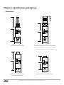
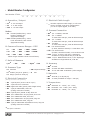
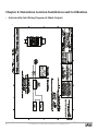
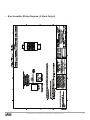
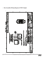
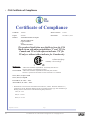
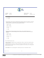
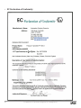
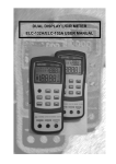
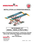
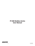
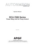
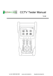
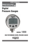
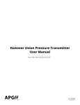
PT-400 User Manual APG R Doc #9002825 Rev C, 09/14 Table of Contents Introduction................................................................................................................. iii Warranty and Warranty Restrictions..................................................................... iv Chapter 1: Specifications and Options..................................................................... 1 Dimensions.........................................................................................................................................1 Specifications.................................................................................................................................... 2 Model Number Configurator........................................................................................................... 3 Electrical Connectors and Pinout Table...................................................................................... 4 Chapter 2: Installation and Removal Procedures and Notes...............................5 Tools Needed...................................................................................................................................... 5 Mounting Instructions.................................................................................................................... 5 Electrical Installation...................................................................................................................... 5 Removal Instructions...................................................................................................................... 5 Chapter 3: Maintenance..............................................................................................6 General Care....................................................................................................................................... 6 Zero Trimming................................................................................................................................... 6 Re-Calibration.................................................................................................................................... 7 Repair and Returns........................................................................................................................... 7 Chapter 4: Hazardous Location Installation and Certification...........................8 Intrinsically Safe Wiring Diagram................................................................................................ 8 Non-Incendive Wiring Diagrams.............................................................................................. 9-11 CSA Certificate of Compliance................................................................................................ 12-15 EC Declaration of Conformity...................................................................................................... 16 ii Tel: 1/888/525-7300 • Fax: 1/435/753-7490 • www.apgsensors.com • [email protected] Introduction Thank you for purchasing a PT-400 series pressure transmitter from APG. We appreciate your business! Please take a few minutes to familiarize yourself with your PT-400 and this manual. The PT-400 series of pressure transmitters offers reliability over a wide range of pressures and in harsh industrial conditions and hazardous locations. It is certified intrinsically safe for hazardous areas in the US, Canada, Europe and internationally by CSA, ATEX, and IECEx for Class 1, Zone 0 environments. The small size, integrated electronics, wide operating temperature range, and durability, make the PT-400 the perfect instrument for static and dynamic pressure measurements with an amplified output signal. Reading your label Every APG instrument comes with a label that includes the instrument’s model number, part number, serial number, and a wiring pinout table. Please ensure that the part number and pinout table on your label match your order. The following electrical ratings and approvals are also listed on the label. Please refer to the Certificate of Compliance and Declaration of Conformity at the back of this manual for further details. Electrical ratings Input: 9 to 28 Volts DC; Outputs: 4-20mA / 0-5VDC / 0-10VDC (per order) Exia Class I Division 2; Groups C, D T4 Class I, Zone 2, Group IIB AEx nC IIB T4: Ta: -40°C to 85°C Ex nL IIB T4: Ta: -40°C to 85°C Maximum Working Pressure: 10,000 PSI PT-400-L1 (4-20mA) Vmax Ui= 28VDC, Imax Ii = 110mA, Pmax Pi = 0.77W, Ci = 0.055μF, Li = 7.95μH Install in accordance with drawing 9002794, sheet 2 (page 9). PT-400-L3/L10 (0-5V/0-10V) Vmax Ui= 28VDC, Imax Ii = 110mA, Pmax Pi = 0.77W, Ci = 0μF, Li = 0μH Install in accordance with drawing 9002794, sheets 3 & 4 (page 10 & 11). Input: 9 to 28 Volts DC; Output: 4-20mA (per order) Exia Class I Division 1; Groups C, D T4 Class I, Zone 0, Group IIB AEx ia IIB T4: Ta: -40°C to 85°C Ex ia IIB T4: Ta: -40°C to 85°C Maxium Working Pressure: 10,000 PSI Vmax Ui= 28VDC, Imax Ii = 110mA, Pmax Pi = 0.77W, Ci = 0.055μF, Li = 7.95μH Install in accordance with drawing 9002794, sheet 1 (page 8). IMPORTANT: Your PT-400 MUST be installed according to drawing 9002794 (Intrinsically Safe Wiring Diagram or Non-Incendive Wiring Diagrams) as indicated above to meet listed approvals. Faulty installation will invalidate all safety approvals and ratings. Tel: 1/888/525-7300 • Fax: 1/435/753-7490 • www.apgsensors.com • [email protected] iii The following approvals only apply to the L1 (4-20mA) version ATEX Directive: 0518 Sira 12ATEX 2294 II 1G Ex ia IIB T4 Ga Ta: -40°C to 85°C Ui ≤ 30 V, Ii ≤ 110 mA, Pi ≤ 1 W, Ci ≤ 60.89 nF, Li ≤ 10.95 μH IECEx CSA 13.0004 Ex ia IIB T4 Ga Warranty and Warranty Restrictions APG warrants its products to be free from defects of material and workmanship and will, without charge, replace or repair any equipment found defective upon inspection at its factory, provided the equipment has been returned, transportation prepaid, within 24 months from date of shipment from factory. THE FOREGOING WARRANTY IS IN LIEU OF AND EXCLUDES ALL OTHER WARRANTIES NOT EXPRESSLY SET FORTH HEREIN, WHETHER EXPRESSED OR IMPLIED BY OPERATION OF LAW OR OTHERWISE INCLUDING BUT NOT LIMITED TO ANY IMPLIED WARRANTIES OF MERCHANTABILITY OR FITNESS FOR A PARTICULAR PURPOSE. No representation or warranty, express or implied, made by any sales representative, distributor, or other agent or representative of APG which is not specifically set forth herein shall be binding upon APG. APG shall not be liable for any incidental or consequential damages, losses or expenses directly or indirectly arising from the sale, handling, improper application or use of the goods or from any other cause relating thereto and APG’s liability hereunder, in any case, is expressly limited to the repair or replacement (at APG’s option) of goods. Warranty is specifically at the factory. Any on site service will be provided at the sole expense of the Purchaser at standard field service rates. All associated equipment must be protected by properly rated electronic/electrical protection devices. APG shall not be liable for any damage due to improper engineering or installation by the Purchaser or third parties. Proper installation, operation and maintenance of the product becomes the responsibility of the user upon receipt of the product. Returns and allowances must be authorized by APG in advance. APG will assign a Return Material Authorization (RMA) number which must appear on all related papers and the outside of the shipping carton. All returns are subject to the final review by APG. Returns are subject to restocking charges as determined by APG’s “Credit Return Policy”. iv Tel: 1/888/525-7300 • Fax: 1/435/753-7490 • www.apgsensors.com • [email protected] Chapter 1: Specifications and Options • Dimensions 5.80 147.32 1025 West 1700 N Logan, Utah USA 888.525.7300 Automation Products Group, Inc. Model #: Part #: Output: Range: Serial #: Made in USA Wiring: Pin A: + Exc Pin B: - Exc Pin C: N/C Pin D: N/C Pin E: N/C Pin F: N/C Date: Due: = Automation Products Group, Inc. 4.45 113.03 Model #: Part #: Output: Range: Serial #: Made in USA Mfg: 1025 = W 1700 N Logan, Utah USA 888.525.7300 Pin Pin Pin Pin Pin Pin Wiring A: +Ex Date: B: -Ex Due: C: N/C D: N/C E: N/C F: N/C Mfg: 1.50 38.10 1.50 38.10 PT-400 with Pigtail and NPTM PT-400 with DIN 43650 and L-Bracket and NPTM Total length of PT-400 with DIN 43650 and L-Bracket is equal to total length of PT-400 with Pigtail. 4.50 114.30 Automation Products Group, Inc. Model #: Part #: 1025 W 1700 N Logan, Utah USA 888.525.7300 Output: Range: Serial #: Made in USA Pin Pin Pin Pin Pin Pin Wiring A: +Ex Date: B: -Ex Due: C: N/C D: N/C E: N/C F: N/C Mfg: 3.50 88.90 Automation Products Group, Inc. Model #: Part #: Output: Range: Serial #: Made in USA 1.50 38.10 PT-400 with 4 or 6 pin Bayonet on Extended Can and NPTF 1025 W 1700 N Logan, Utah USA 888.525.7300 Pin Pin Pin Pin Pin Pin Wiring A: +Ex Date: B: -Ex Due: C: N/C D: N/C E: N/C F: N/C Mfg: 1.50 38.10 PT-400 with 4 or 6 pin Bayonet and NPTF Tel: 1/888/525-7300 • Fax: 1/435/753-7490 • www.apgsensors.com • [email protected] 1 • Specifications Performance Pressure Ranges Analog Output Over Pressure Burst Pressure 0 to 40K PSIS (Per Part Number) 4-20mA, 0-5VDC, 0-10VDC 2X Full Scale or limit of fitting, whichever is less 3.0X Full Scale or limit of fitting, whichever is less Accuracy Linearity, Hystereses & Repeatability Thermal Zero Shift Thermal Span Shift ±0.25% of Full Scale (BFSL) [±0.036% FSO/°C (±0.02% FSO/°F)] [±0.036% FSO/°C (±0.02% FSO/°F)] Environmental Operating Temperature Compensated Temperature Enclosure Protection -40 to 85°C -17 to 54°C IP65 (-40 to 185°F) (0 to 130°F) Electrical Supply Voltage (at sensor) Output Signal @ 21°C 4-20 mA: 0 to 5 VDC: 0 to 10 VDC: 4-20 mA: 0 to 5 VDC: 0 to 10 VDC: 9-28 VDC 9-28 VDC 12.5-28 VDC 3-30 mA max. 7mA max 14mA max Masterials of Construction Wetted Materials Enclosure 316L or 17-4 Stainless Steel 316L Stainless Steel Mechanical 2 Pressure Connection Weight See model number configurator for complete list 283g (10 oz.) Tel: 1/888/525-7300 • Fax: 1/435/753-7490 • www.apgsensors.com • [email protected] • Model Number Configurator Part Number: PT-400 - _____ - _____ - _____ - _____ - _____ - _____ - _____ - _____ - _____ - _____ A B C D E F G H I J A. Operation / Output F. Electrical Cable Length □ L1▲ 4 - 20 mA output □ L3 0 - 5 VDC output □ L10 0 - 10 VDC output □ __ Number represents cable length, in 5-ft incre ments, included on E5, E19, & E38 options. (ex. E5-10 equals pigtail, 10 ft cable) G. Process Connection Modbus □ L5 RS-485 (Modbus/RTU), 4-wire □ P0▲ 1/4 - 18 NPTM, 316L SS □ P1 1/2 - 14 NPTM Pressure reading only (Approvals Pending) □ L31 RS-485 (Modbus/RTU), 4-wire Level calculations, tank volume (Approvals Pending) 17-4 SS above 500 psi; 316L SS below 500 psi 17-4 SS above 500 psi; 316L SS below 500 psi 17-4 SS above 500 psi; 316L SS below 500 psi (F-250C, Autoclave female) 17-4 SS above 10K (M-250C, Autoclave female) 17-4 SS above 10K Available on ranges below 500 psi, 316L SS C. Units of Measure Available on ranges below 5K, 316L SS □ bar □ kPa □ kgcm2 □ fsw □ psi▲ D. Pressure Type □ A Absolute □ CG Compound Gauge ▲ □ S Sealed (100 psi or greater) □ V VAC □ G Gauge (less than 1000 psi) H. Accuracy B. Common Pressure Ranges - PSI* □5 □ 50 □ 200 □ 1000 □ 5000 □ 15 □ 30 □ 60 □ 100 □ 300 □ 500 □ 2000 □ 3000 □ 10000 *Other ranges available. Please consult factory. E. Electrical Connection (Mating connector sold separately) □ E3 4 pin bayonet (PT 1H-8-4P or equiv.) □ E4 4 pin M12 micro connector. □ E5▲ Pigtail with cable (specify cable length below) □ E6 4 pin per DIN 43650, short can □ E17 □ E18 □ E19 □ E36 □ E38 □ E39 (mating connector included) 6 pin bayonet (PT02E-10-6P) short can 1/2 in NPTM with 6 in flying leads, short can 1/2 in NPTM with cable, short can 1/2 in NPTM with 6 in flying leads, long can 1/2 in NPTM with cable, long can 4 pin per DIN 43650 w/Solderless screw, long can (mating connector included) □ P5 1/4 - 18 NPTF □ P6 1/2 NPTF □ P9 H.P. SnoTrik female □ P30 H.P. SnoTrik male □ P38 1 1/2 in. tri-clover with 3/4 in. diaphragm □ P52 1 1/2 in. NPTM flushmount w/ 1/2in. diaphragm □ N0▲±0.25% □ N1 ±0.25% with NIST certification □ N2 ±0.1% with NIST certification (select ranges) I. Materials □ M1▲ 316L SS (1 to 40,000 psi) □ M2 17-4 SS (available on ranges > 200 psi) J. Temperature □ S0▲ Standard: 0º - 130ºF (-17º - 54ºC) □ S1 Extended: -40º - 180ºF (-40º - 82ºC) □ S4 Extended: 0º - 185ºF (-17º - 85ºC) ▲This option is standard Tel: 1/888/525-7300 • Fax: 1/435/753-7490 • www.apgsensors.com • [email protected] 3 • Electrical Connectors, Pinout Table, and Supply Power Table Bayonet Bayonet DIN M12 Pigtail 4-20 mA 0-5 VDC 0-10 VDC A + Excitation + Excitation + Excitation B - Excitation + Output + Output C N/C - Output - Output D N/C - Excitation - Excitation E N/C N/C N/C F N/C N/C N/C A + Excitation + Excitation + Excitation B - Excitation + Output + Output A D C N/C - Output - Output B C D N/C - Excitation - Excitation 1 + Excitation + Excitation + Excitation 2 - Excitation + Output + Output 3 N/C - Out/Exc - Out/Exc 4 Ground Ground Ground 1 + Excitation + Excitation + Excitation 2 N/C + Output + Output 3 N/C - Output - Output 4 - Excitation - Excitation - Excitation Red + Excitation + Excitation + Excitation Grn N/C + Output + Output Wht N/C - Output - Output Blk - Excitation - Excitation - Excitation F E A B C D 4 1 2 4 4 Pin Bayonet Connector DIN Connec- 4 Pin M12 1 2 Bayonet Connector tor 3 3 6 Pin 4 Pin + 4 Pin 4 Pin 4 Pin 6 Pin PT-400 Series Pin Out Table Micro Connector N/C indicates no connection For alternate pinouts, please consult factory PT-400 Series Supply Power Table Power Supply 4 4-20 mA 0-5 VDC 0-10 VDC 9-28 VDC 9-28 VDC 12.5-28 VDC Tel: 1/888/525-7300 • Fax: 1/435/753-7490 • www.apgsensors.com • [email protected] Chapter 2: Installation and Removal Procedures and Notes • Tools Needed • Wrench sized appropriately for your PT-400’s process connection. • Thread tape or sealant compound for threaded connections. • Mounting Instructions Mounting your pressure transducer is easy if you follow a few simple steps: • Never over-tighten the sensor. This can compress the diaphragm, changing how it reacts to pressure. In all cases, tigthen the sensor as little as possible to create an adequate seal. On straight threads, tighten only until you feel the o-ring compress - making sure you don’t damage or extrude the o-ring. • Always use thread tape or sealant compound on tapered threads. Wrap thread tape in the opposite direction of the threads so it does not unravel as you screw the sensor into place. Unraveling can cause uneven distribution and seal failure. For straight threads use an o-ring. • Always start screwing in your sensor by hand to avoid cross-threading. Thread failure can be a problem if you damage threads by over-tightening them or by crossing threads. • Electrical Installation • Check the pinout table on your PT-400 against your order. • Check that your electrical system wiring matches the pinout table on your PT-400. • For instruments with connectors, make the connection. Otherwise, attach your wires to the provided terminal strip. • Removal Instructions Removing your PT-400 from service must be done with care. It’s easy to create an unsafe situation, or damage your sensor, if you are not careful to follow these guidelines: • Make sure the pressure is completely removed from the line or vessel where your sensor is installed. Follow any and all procedures for safely isolating any media contained inside the line or vessel. • Remove the sensor with an appropriately sized wrench (per your process connection). • Clean the sensor’s fitting and diaphragm of any debris (see General Care) and inspect for damage. • Store your sensor in a dry place, at a temperature between -40° F and 180° F. DANGER: Removing your PT-400 Pressure Transmitter while there is still pressure in the line could result in injury or death. Tel: 1/888/525-7300 • Fax: 1/435/753-7490 • www.apgsensors.com • [email protected] 5 Chapter 3: Maintenance • General Care Your PT-400 series pressure transmitter is very low maintenance and will need little care as long as it was installed correctly. However, in general, you should: • Keep the transmitter and the area around it generally clean. • Avoid applications for which the transmitter was not designed, such as extrememe temperatures, contact with incompatible corrosive chemicals, or other damaging environments. • Inspect the threads whenever you remove the transmitter from duty or change its location. • Avoid touching the diaphragm. Contact with the diaphragm, especially with a tool, could permanently shift the output and ruin accuracy. • Clean the diaphragm or the diaphragm bore with extreme care. If using a tool is required, make sure it does not touch the diaphram. • Zero Trimming • Remove the protective screw. • Ensure that the transmitter is at 0 psig or 0 psia (vacuum if absolute). For compound ranges, i.e., -15 psi to 30 psi, the 4 mA or 0 V set point is also at vacuum. • Using a jeweler’s screwdriver or a suitable instrument, adjust the “Z” pot until you have a 4 mA (4-20 mA) or 0 V (5 VDC, 10 VDC) output. IMPORTANT: Do not make changes to the Span adjustment (the “S” pot to the right, see Figure 3.1) as part of the zero trimming. The Span should only be changed as part of the recalibration of a gauge with a known pressure source. Zero & Span Adjustment Figure 3.1 6 Tel: 1/888/525-7300 • Fax: 1/435/753-7490 • www.apgsensors.com • [email protected] • Re-Calibration This procedure requires a known pressure source of at least ±0.1% accuracy in order to fully utilize the accuracy potential of the PT-400. (If not available, you can return it to the factory for re-calibration.) • Ensure that the transducer is at 0 psig or 0 psia (vacuum if absolute), and adjust zero as per instructions for zero trimming. • Apply full scale pressure to the pressure port and adjust the Span (“S”) pot (on the right of Figure 3.1) until the full scale signal is reached. • Re-check zero and re-adjust the zero (“Z”) pot if required • Repeat previous two steps until no further adjustment is required. NOTE: You may also return the PT-400 to the factory for repair and/or adjustment. • Repair and Returns Should your PT-400 series pressure transmitter require service, please contact the factory via phone, email, or online chat. We will issue you a Return Material Authorization (RMA) number with instructions. • Phone: 888-525-7300 • Email: [email protected] • Online chat at www.apgsensors.com Please have your PT-400’s part number and serial number available. See Waranty and Warranty Restrictions for more information. Tel: 1/888/525-7300 • Fax: 1/435/753-7490 • www.apgsensors.com • [email protected] 7 Chapter 4: Hazardous Location Installation and Certification • Intrinsically Safe Wiring Diagram (4-20mA Output) 8 Tel: 1/888/525-7300 • Fax: 1/435/753-7490 • www.apgsensors.com • [email protected] • Non-Incendive Wiring Diagram (4-20mA Output) Tel: 1/888/525-7300 • Fax: 1/435/753-7490 • www.apgsensors.com • [email protected] 9 • Non-Incendive Wiring Diagram (0-5VDC Output) 10 Tel: 1/888/525-7300 • Fax: 1/435/753-7490 • www.apgsensors.com • [email protected] • Non-Incendive Wiring Diagram (0-10VDC Output) Tel: 1/888/525-7300 • Fax: 1/435/753-7490 • www.apgsensors.com • [email protected] 11 • CSA Certificate of Compliance CertificateofCompliance Certificate: 1984045 MasterContract: 237484 Project: 2587208 DateIssued: December 17, 2012 Issuedto: AutomationProductsGroupInc 1025West1700North Logan,UT84321 USA Attention:KarlReid The products listed below are eligible to bear the CSA Mark shown with adjacent indicators 'C' and 'US' for Canada and US or with adjacent indicator 'US' for US only or without either indicator for Canada only. Eshwar Kashyap Issuedby: Eshwar Kashyap PRODUCTS CLASS225803 CLASS225883 - PROCESS CONTROL EQUIPMENT - Intrinsically Safe and Non Incendive Systems - For Hazardous Locations - PROCESS CONTROL EQUIPMENT-Intrinsically Safe and NonIncendive - Systems-For Hazardous Locations-Certified to U.S. Standards ClassI,Div.2,GroupsCandD ClassI,Zone2,GroupIIB ExnLIIBT4;Ta:-40°C...+85°C AExnCIIBT4;Ta:-40°C...+85°C • Model PT-400-L1xxxx Pressure Transmitter. Rated 9-28VDC, 4-20mA. Maximum Ambient 85° C; Temperature Code T4; Maximum Working Pressure 10,000 PSI. Enclosure type: IP65. Installed as per Drawing 9002794. Non-Incendive with the following Entity Parameters: Vmax, Ui = 28V Imax, Ii = 110mA Pmax, Pi = 0.77W DQD 507 Rev. 2012-05-22 12 Page: 1 Tel: 1/888/525-7300 • Fax: 1/435/753-7490 • www.apgsensors.com • [email protected] Certificate: 1984045 MasterContract: 237484 Project: 2587208 DateIssued: December 17, 2012 Ci = 0.055µF Li = 7.95µH • Model PT-400-L3/L10xxxx Pressure Transmitter. Rated 9-28VDC, 4-20mA or 0-5V, 20mA or 0-10V, 20mA; Maximum Ambient 85° C; Temperature Code T4; Maximum Working Pressure 10,000 PSI. Installed as per Drawing 9002794. Non-Incendive with the following Entity Parameters: Vmax, Ui = 28V Imax, Ii = 110mA Pmax, Pi = 0.77W Ci = 0µF Li = 0µH • Model PT-500-xxxx Pressure Transmitter, Rated 10-28VDC, 4-20mA; Maximum Ambient 85° C; Temperature Code T4; Maximum Working Pressure 10,000 PSI; Non-Incendive with the following Entity Parameters: Vmax, Ui = 28V Imax, Ii = 110mA Pmax, Pi = 0.77W Ci = 0µF Li = 0µH Notes for Models PT-400, PT-500: 1. The "x" in the Model designations may be any alpha-numeric character, to denote minor mechanical options, not affecting safety. 2. These devices must be connected to a suitably certified and approved apparatus that provides non-incendive outputs either equal to or less than those as indicated by the applicable control drawings. This certified apparatus must be located in a safe area. CLASS225804-Process Control Equipment - Intrinsically Safe, Entity - For Hazardous Locations DQD 507 Rev. 2012-05-22 Page: 2 Tel: 1/888/525-7300 • Fax: 1/435/753-7490 • www.apgsensors.com • [email protected] 13 Certificate: 1984045 MasterContract: 237484 Project: 2587208 DateIssued: December 17, 2012 CLASS225884- Process Control Equipment - Intrinsically Safe, Entity - For Hazardous Locations - Certified to US Standards ClassI,Div.1,GroupsC,D ClassI,Zone0,GroupIIB ExiaIIBT4;Ta:-40°C...+85°C AExiaIIBT4;Ta:-40°C...+85°C • Model PT-400-L1xxxx Pressure Transmitter. Rated 9-28VDC, 4-20mA. Maximum Working Pressure: 10,000 PSI. Installed as per Drawing 9002794. Ambient Range: -40°C to +85°C. Enclosure type: IP65. Intrinsically safe with the following entity parameters: Vmax, Ui = 28V Imax, Ii = 110mA Pmax, Pi = 0.77W Ci = 0.055µF Li = 7.95µH • Model PT-500-xxxx Pressure Transmitter; Maximum Ambient 85° C; Temperature Code T4; Maximum Working Pressure 10,000 PSI; Entity parameters as follows: Vmax, Ui = 28V Imax, Ii = 110mA Pmax, Pi = 0.77W Ci = 0.042µF Li = 0.320µH Notes for Models PT-400, PT-500: 1. The "x" in the Model designations may be any alpha-numeric character, to denote minor mechanical options, not affecting safety. 2. These devices must be connected to a NRTL approved safety barrier (located in a safe area). DQD 507 Rev. 2012-05-22 14 Page: 3 Tel: 1/888/525-7300 • Fax: 1/435/753-7490 • www.apgsensors.com • [email protected] Certificate: 1984045 MasterContract: 237484 Project: 2587208 DateIssued: December 17, 2012 APPLICABLEREQUIREMENTS C22.2 No 0 - M1991 C22.2 No 0.4 - M2004 C22.2 No 142 - M1987 C22.2 No 157 - M1992 C22.2 No 213 - M1987 CAN/CSA-C22.2 No. 60079-0:11 CAN/CSA-C22.2 No. 60079-11:11 CAN/CSA-C22.2 No. 60079-15:12 CAN/CSA-C22.2 No. 60529:05 UL 508, 17th Edition UL 913, 7Th Edition ANSI/ISA-12.12.01-2007 ANSI/UL 60079-0:09 ANSI/UL 60079-11:09 ANSI/UL 60079-15:09 ANSI/IEC 60529:2004 DQD 507 Rev. 2012-05-22 General Requirements - Canadian Electrical Code Part II. Bonding and Grounding of Electrical Equipment (Protective Grounding). Process Control Equipment. Intrinsically Safe and Non-Incendive Equipment for Use in Hazardous Locations. Non-Incendive Electrical Equipment for Use in Class I, Division 2 Hazardous Locations. Explosive Atmospheres - Part 0: Equipment - General requirements Explosive Atmospheres – Part 11: Equipment protection by intrinsic safety "i" Electrical apparatus for explosive gas atmospheres - Part 15: Construction, test and marking of type of protection “n” electrical apparatus Degrees of protection provided by enclosures (IP Code) Industrial Control Equipment. Intrinsically Safe Apparatus and Associated Apparatus for use in Class I, II, III, Division 1, Hazardous (Classified) Locations. Nonincendive Electrical Equipment for Use in Class I and II, Division 2 and Class III, Divisions 1 and 2 Hazardous (Classified) Locations Electrical Apparatus for Explosive Gas Atmospheres Part 0: General Requirements Electrical apparatus for Explosive Gas Atmospheres Part 11: Intrinsic Safety “i” Electrical apparatus for Explosive Gas Atmospheres Part 15: Type of Protection “n” Degrees of Protection Provided by Enclosures (IP Code) Page: 4 Tel: 1/888/525-7300 • Fax: 1/435/753-7490 • www.apgsensors.com • [email protected] 15 • EC Declaration of Conformity 16 Tel: 1/888/525-7300 • Fax: 1/435/753-7490 • www.apgsensors.com • [email protected] APG R Automation Products Group, Inc. Tel: 1/888/525-7300 • Fax: 1/435/753-7490 • www.apgsensors.com • [email protected]