1
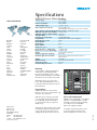
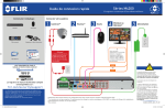
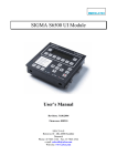
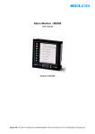
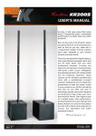
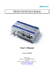
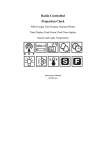
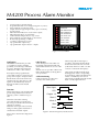
M4200 Process Alarm Monitor
•
•
•
•
•
•
•
•
•
•
•
•
Compact unit for flush mounting
Programmable LED colour change (red, green or yellow)
Special indication of the first alarm
8 input channels supporting normally open or normally
closed contacts
Individual LED indication of each of the 8 inputs
Individual time delay on all channels
2 individual blocking modes for easy service
Special indication of cable break or short circuit
PC based programming via RS232
1 common output relay for siren
2 programmable output relays
3 programmable “Open Collector” outputs
1
OVERLOAD
2
HIGH WATER TEMP.
3
LOW FREQUENCY
4
HIGH FREQUENCY
5
FUEL LEVEL LOW
6
FUEL LEAKAGE
7
VALVE 1 OPEN
8
VALVE 2 OPEN
RESET
TEST
POWER
ON
ALARM
Figure 1. Front of M4200
Application
Label layout
The M4200 Alarm Monitor provides
a cost effective solution, with the
possibility of monitoring 8 individual
processes. All inputs will accept any
combination of NO or NC contacts.
A text description for the LEDs can
be printed on the blank legend card
situated between the two covers at the
front.
SELCO A/S also provides a Microsoft®
Office Word template for doing this in
an easy manner.
Each input can be programmed to
control both of the two alarm relays for
group alarm outputs. All inputs will in
default mode activate the alarm relay
and the siren relay. The delays for the
inputs can be individually selected
between 25 milliseconds and 999
seconds.
Function
When alarm input is activated, the LED
goes flashing and the interconnected
output(s), alarm 1 and the siren goes
ON.
When the reset button is being
activated, the LED goes steady and
the siren goes OFF. The interconnected
output(s) is still ON.
When the alarm input is de-activated,
LED goes OFF, together with alarm 1
and the interconnected outputs.
Please refer to the function diagram in
figure 2.
Cable Monitoring
Cable monitoring provides extra
security to the alarm system.
When using cable monitoring it is
possible to translate both cable break
and short circuit faults into an alarm
(cable fault) whenever a NO or an NC
contact is connected to the input(s).
Cable faults are indicated with short
flashing pulses on the corresponding
alarm channels. Cable fault indications
will be overridden by activation of
input alarms and indicated with normal
flash or steady light indication.
Alarm input
LED
Output 1-4
Alarm 1
Alarm 2
Siren
Reset
Figure 2. Function Diagram, Default Scenario
Specifications
Dimming
1 IN1
2 IN2
3 IN3
4 IN4
5 IN5
6 IN6
I
N
P
U
T
S
Sunken into the rear of the Alarm
Monitor, one rotary switch and two dip
switches are positioned.
With the rotary switch it is possible
to select which part of the program
to be adjusted, channel selection (18), operational mode (0) or general
functions (9).
Main office:
SELCO A/S
Betonvej 10
DK-4000 Roskilde
Denmark
Phone: + 45 7026 1122
Fax:
+ 45 7026 2522
e-mail: [email protected]
www.selco.com
With the two dip switches it is possible
to adjust the program selected on the
rotary switch, e.g. time delay, reset
settings, block mode, LED colour etc.
9 01
10 GND
13 BLOCK1
OUT1 19
OUT2 20
OUT3 21
OUT4 22
SYNC 23
5
POWER
25
- 26
27
ON DIP
11 RESET
12 TEST
23
Programming
9 +REF OUT
O
U
T
P
U
T
S
+ 24
7 IN7
8 IN8
Dimming is done in 8 consecutive
levels. The default brightness level is
re-obtained when the lowest level has
been obtained.
Betonvej 10
DK-4000 Roskilde
Phone: +45 70261122
Fax:
+40 70262522
Internet: www.selco.com
1 2 3 4 5 6 7 8
28
ALARM1
29
30
14 BLOCK2
ON DIP
15 GND
1 2 3 4 5 6 7 8
31
ALARM2
33
RS232
ACK
SET
32
34
SIREN
35
Figure 3. Rear of M4200
PC based configuration
M4200 can be configured via the RS232
interface. A standard ANSI / VT100
terminal is used as the programming
tool. SELCO A/S recommends
Microsoft® Hyper Terminal.
For further information please refer
to the User Manual which can be
downloaded from www.selco.com.
M4295-84UK
It is possible to adjust the brightness
of the LEDs on all multiple units
by pressing the button “Test” or the
external positioned button connected to
terminal 11, for more than 10 seconds.
7 8
New Zealand
Norway
Pakistan
Peru
Philippines
Poland
Portugal
Romania
Russia
Singapore
South Africa
South Korea
Spain
Sri Lanka
Sweden
Taiwan
Thailand
Turkey
United Kingdom
U.S.A.
Venezuela
Vietnam
Voltage supply
8.4 - 60 VDC
8.4 - 50 VAC
Power Consumption Max 180mA
Ambient temp. range ÷15 ºC / +70 ºC
Relay output (load capacity) Max. 250VAC / 6A
Regarding DC load capacity, refer to the user manual
Open collector output (load capacity)Max. 60VDC / 700mA per output
LED flash frequency: Slow flashing 1.25Hz ±10%
LED flash frequency: Quick flashing 5Hz ±10%
Min. input delay 25 m. Sec
Resistance in sensing cable 1000Ω (full length)
Programming
Dip switches or PC based configuration
RS232 Bits per second 9600
RS232 Data bit 8
RS232 Parity None
RS232 Stop bit 1
RS232 Flow control
None
RS232 Line delay (ASCII Setup)
50 milliseconds
RS232 Character delay (ASCII Setup) 0 milliseconds
Burn-in 50 hours before final test
Maritime application standards
IEC 60945
EN 61000-4-3, EN 61000-4-4, EN 61000-4-5,
Industrial application standards
EN 61000-4-6
Weight 0.222 Kg
Dimension (mm)
96 x 96 x 20 (H x W x D)
Panel cut out (mm)
92 x 92
Protection degree at front IP 54
6
Belgium
Brazil
Bulgaria
Canada
Chile
China
Croatia
Egypt
Finland
France
Germany
Greece
Iceland
India
Indonesia
Iran
Italy
Japan
Lebanon
Malaysia
Mexico
Netherlands
M4200 Process Alarm Monitor
4
SELCO Worldwide