1
M4010/M4011/M4012
User’s Manual
Systems Engineering Associates, Inc.
14989 West 69th Avenue
Arvada, Colorado 80007 U.S.A.
Telephone: (303) 421-0484
Fax: (303) 421-8108
06/2001
M4010/M4011/M4012
User’s Manual
Copyright © 1991 Systems Engineering Associates, Inc.
Revision 1, November 1993
All Rights Reserved!
CONTENTS
1. General Description
1.1
1.2
1.3
1.4
1.5
1.6
1.7
1.8
1
Programming
Program Execution Times
Digital Inputs
Interrupt Inputs
Digital Outputs
Interface Ports
Diagnostics/Fault Detection
LED Status Indications
1
1
1
2
2
2
3
3
2. Program Structure
5
3. System Configuration
7
3.1
3.2
3.3
3.4
3.5
3.6
Target Board
Network Baud Rate
Input0 Interrupt Enable
Input1 Interrupt Enable
Fixed Scan Time Mode
Timed Interrupt
7
7
7
8
8
8
4. Variable Types/Memory Map
11
4.1
Variables
4.1.1 Flags (F)
4.1.2 Bytes (B)
4.1.3 Words (W)
4.1.4 Port-Pins (P)
4.1.5 Inputs (X)
4.1.6 Outputs (Y)
4.1.7 Constants
11
11
12
13
13
14
15
16
4.2
Data Memory
4.2.1 Volatile Data Memory
4.2.2 Non-Volatile (Battery-Backed) Data Memory
16
17
18
4.3
4.4
I/O Image Addressing
Special Function Variables
4.4.1 F104: User Port RS-232 PROG Port as
User Port
4.4.2 B62 – B64: Timed Interrupt Immediate
Input Variables
19
20
M4010/M4011/M4012 User’s Manual
20
21
SYSTEMS Electronics Group
-i-
CONTENTS
5. Programming Reference
23
5.1
Instruction Set
5.1.1 Ladder
5.1.2 High-Level (‘C’)
5.1.3 Assembly
23
23
24
24
5.2
System Functions
5.2.1 System Function Types
5.2.2 sfunc04: ASCII String Load Command
5.2.3 sfunc07: General External Address Read
5.2.4 sfunc08: General External Address Write
5.2.5 sfunc09: System Fault Routine
5.2.6 sfunc10: USER PORT Receive
5.2.7 sfunc11: USER PORT Transmit
5.2.8 sfunc13: Serial Network Communications
25
25
26
27
28
28
29
29
30
6. Serial Network Communications
6.1
6.2
31
Communicating on the Network (sfunc13)
USER Port (PROG Port) Communications
6.2.1 Receiving Through the User Port (sfunc10)
6.2.2 Transmitting Through the User Port (sfunc11)
7. Fault Detection
7.1
7.2
7.3
7.4
31
33
33
34
35
Fault Routine Execution
Viewing Fault Codes with SYSdev
Fault Codes
7.3.1 Watchdog Timer Timeout (40H)
7.3.2 IBM PC to M4000 Communications
Failure (42H)
7.3.3 Invalid Program Faults (5cH and 5dH)
7.3.4 User Program sfunc09 System Fault Call (45H)
7.3.5 Internal M4000 Faults (43H, 44H, 59H-5bH)
35
35
37
37
Serial Network Communications Errors
7.4.1 Serial Network Comm Error Codes
7.4.2 No Response from Slave (04H and 05H)
7.4.3 Serial Network Integrity Error
(03H, 06H-0eH, 10H)
7.4.4 Address Outside Range (0fH)
40
40
41
8. Hardware Confidence Test
38
39
39
39
41
41
43
8.1
8.2
Tests Performed
Performing the Hardware Confidence Test
8.2.1 Equipment Required
8.2.2 Executing the Test
43
44
44
44
8.3
Interactive Interface
45
M4010/M4011/M4012 User’s Manual
SYSTEMS Electronics Group
- ii -
CONTENTS
9. Installation
47
9.1
9.2
9.3
9.4
9.5
9.6
9.7
Mounting the M4010/11/12
Wiring Input Power
Wiring 10-30VDC Digital Inputs
Wiring Interrupt Inputs
Wiring 10-30VDC Digital Outputs
Wiring the Fault Interlock
Serial Network Installation
9.7.1 Wiring the Serial Network
9.7.2 Setting the Network Addresses
47
47
48
49
50
51
52
52
54
9.8
Power-up Sequence of M4000 Modules
54
APPENDICES
Programming Example
RS-232 Pinouts/Cables
Field Wiring Connector Pinouts
M4010/M4011/M4012 User’s Manual
Appendix A
Appendix B
Appendix C
SYSTEMS Electronics Group
- iii -
SECTION 1
GENERAL DESCRIPTION
The M4010, M4011, and M4012 PLC modules are high performance programmable logic controller
modules which incorporate a built-in processor, user program (24K bytes) and data memory (2K
bytes), 10-30VDC digital inputs, 10-30VDC digital outputs, RS-232 programming port and a serial
network interface port. Throughout this manual, the M4010, M4011, and M4012 modules will be
generically referred to as the "M4000 modules".
________________________________________________________________________________
1.1 PROGRAMMING
Programming of the M4010/11/12 modules is implemented using SYSdev, an IBM PC or
compatible software package which allows the user to create, document, and compile the user
application program as well as directly interface to the M4010/11/12 for program download and online monitoring. The program is developed off-line, compiled, and then downloaded to the module.
SYSdev allows the M4010/11/12 to be programmed in a combination of languages: Ladder, Highlevel (subset of C) and Assembly (MCS-51).
________________________________________________________________________________
1.2 PROGRAM EXECUTION TIMES
Typical program scan times are on the order of 0.6 milliseconds per K of user program with scan
times as low as 80 microseconds for short programs. Two additional 10-30VDC interrupt inputs
allow throughputs even less than 80 microseconds.
________________________________________________________________________________
1.3 DIGITAL INPUTS
The digital inputs are 10-30VDC sourcing (true high) which are used to interface to the application
inputs such as proximity sensors, pushbuttons, etc. The input is "on" ("1") when the input voltage
exceeds 10VDC and is "off" ("0") when the input voltage is below 5VDC. Individual LED status
indication is provided for each input. All inputs are optically isolated and provided with an input
filter delay (nominally 1.0 milliseconds).
M4010/M4011/M4012 User’s Manual
SYSTEMS Electronics Group
-1-
SECTION 1
GENERAL DESCRIPTION
________________________________________________________________________________
1.4 INTERRUPT INPUTS
The M4000 modules contain two interrupt inputs which allow hardware interrupts to be
implemented in the user's program. The inputs are 12-30VDC differential inputs which can be
enabled as interrupts or disabled and used as standard inputs. When enabled as interrupts, an "off"
to "on" transition of the enabled input, activates an interrupt call to a user programmed file (ufunc00
for input0 and ufunc01 for input1). This suspends the main program file until the interrupt file
execution is completed, at which time program execution resumes at the place in the main file
where the interrupt occurs. This mechanism allows ultra fast throughputs to be implemented if
required.
________________________________________________________________________________
1.5 DIGITAL OUTPUTS
The digital outputs are 10-30VDC sourcing (true high) which are used to interface to the application
outputs such as solenoids, lamps, PLC inputs, etc. Each output is rated at 1 amp DC (continuous)
with an in-rush (pulsed) current drive capability of 5 amps for 100msec. The sum of the current
within an 8 output group must not, however, exceed 6 amps. All outputs are optically isolated and
contain a transient suppression circuit to protect the output when driving inductive loads. The
outputs do not contain output fusing, therefore, external fusing should be provided.
________________________________________________________________________________
1.6 INTERFACE PORTS
The M4010/11/12 modules contain two interface ports: the serial network comm port and the
PROGramming port.
SERIAL NETWORK: The serial network port conforms to the S3000-N1 network. This network
is a high speed (up to 344KBPS), twisted pair, serial network configured in a master/slave topology.
Up to 32 M4010/11/12 modules and/or S3000 processors (node) can be connected on one network.
Communications between the nodes on the network is controlled via commands (sfunc13) in the
user application program resident in the node acting as the master.
PROG PORT: The PROG port is an RS-232 port dedicated for on-line monitoring and program
download when the M4010/11/12 is connected to an IBM PC or compatible running SYSdev.
M4010/M4011/M4012 User’s Manual
SYSTEMS Electronics Group
-2-
SECTION 1
GENERAL DESCRIPTION
________________________________________________________________________________
1.7 DIAGNOSTICS/FAULT DETECTION
The M4010/11/12 contains comprehensive fault detection routines which verify the proper
operation of the module at all times. Each detected fault has a corresponding fault code which can
be viewed using SYSdev, providing a description of the fault and recommended corrective action.
The M4010/11/12 contains a fault interlock (24VDC, 100mAMP, sinking) output which can be
interlocked to the control system for system shut down or annunciation when a fault is detected. In
addition to the fault code detection, a hardware confidence test is resident in the module to provide
a complete test of the module hardware. This test is initiated through SYSdev and can be used to
verify the M4010/11/12 for proper operation.
________________________________________________________________________________
1.8 LED STATUS INDICATIONS
The following four status LEDs are located on the front of the M4010/11/12: PWR, RUN, COMM,
and FLT. The definitions of these LEDs are as follows:
PWR: "On" when +24VDC power is applied to the M4010/11/12.
RUN: "On" steady when the M4010/11/12 is running a valid user's application program. "Off"
when an internal fault is detected or when a valid user's program has not been loaded. The RUN led
is flashed during program download and also when the hardware confidence test is executed.
COMM: This LED is flashed every time an access to the serial network is made by any board or
module on the network. If the LED is on solid, continuous communications is occurring on the
network. If the LED is “off”, no communications is occurring. This is not a fault LED, but simply
an indication of activity on the serial network.
FLT: “ON” when an internally detected fault has occurred in the M4010/11/12. See section 7 for
more details on the fault routines and error codes.
M4010/M4011/M4012 User’s Manual
SYSTEMS Electronics Group
-3-
SECTION 1
GENERAL DESCRIPTION
(This Page Intentionally Left Blank)
M4010/M4011/M4012 User’s Manual
SYSTEMS Electronics Group
-4-
SECTION 2
PROGRAM STRUCTURE
The SYSdev programming language is a combination of Ladder, High-level (subset of C) and
Assembly (MCS-51). All the files shown in the following are programmed in the same language
format. Each file can be written in any combination of the language types. The typical M4010/11/12
user program consists of the following files:
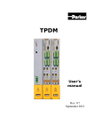
1) Initialization file (optional): executed once at
power up.
POWER-UP
INIT
FILE
2) Main Program file (required): scanned
continuously.
3) Timed Interrupt file (optional): executed once
every 0.5, 1.0, or 10.0 milliseconds as set by the
user.
4) User Function files (optional): up to 100 user
defined subroutines which can be called from any
of the above files.
TIMED
INTERRUPT
MAIN
PROG
FILE
UFUNC
5) Input Interrupts (optional): the two input
interrupts can be enabled or disabled. Input0
interrupt calls ufunc00 when activated (“off” to “on” transition of input0) while input1
interrupt calls ufunc01.
Note: ufunc00 must be created by the user if the input0 interrupt is enabled and ufunc01 if
the input1 interrupt is enabled.
Each file is executed sequentially from beginning to end. The main program file is executed
(scanned) continuously unless interrupted by the timed interrupt or an input interrupt is activated.
When this occurs, main program execution is suspended while the interrupt file is executed. At the
completion of the interrupt, program execution resumes at the point in the main program where the
interrupt occurred.
Each file is implemented as a series of consecutive blocks. Each block is defined as one of the three
programming languages: Ladder, High-level or Assembly. Blocks of the different languages can be
intermixed as necessary within the file.
All M4000 I/O is updated (inputs read, outputs written) at the beginning of each main program
scan. These updates are stored in the ‘X’ and ‘Y’ I/O image bytes of the module (see section 4.1).
M4010/M4011/M4012 User’s Manual
SYSTEMS Electronics Group
-5-
SECTION 2
PROGRAM STRUCTURE
When the timed interrupt is enabled, the 'X' input variables are updated at the beginning of the main
program as normal, however, the 'Y' output variables are updated at the beginning of the timed
interrupt execution instead of the beginning of the main scan. In addition to these I/O updates, the
inputs are read at the beginning of the timed interrupt and stored at special function variables B62B64 (see Section 4.4.2). This in effect constitutes an immediate I/O for the timed interrupt.
Note: ‘Y’ output variables cannot be used as coils in the main program if the timed interrupt is
enabled. Any outputs that are to be activated by the main program file must be passed to the timed
interrupt file as a flag (‘F’ variable) and then mapped to the ‘Y’ output in the timed interrupt.
See the SYSdev Programming Manual for more details on the typical program structure.
M4010/M4011/M4012 User’s Manual
SYSTEMS Electronics Group
-6-
SECTION 3
SYSTEM CONFIGURATION
The system configuration defines the M4000 module configuration that the program will run in.
This includes defining the serial network baud rate, enabling or disabling the input0 and input1
interrupts, and enabling or disabling the fixed scan mode. These parameters are all set through
SYSdev when the program is developed. See the SYSdev Programming Manual for more details.
________________________________________________________________________________
3.1 TARGET BOARD
This is used to select the module that the program will be loaded into. This can be either the M4010,
M4011, M4012, or M4020. Selecting a specific module, enables the complier to generate the
appropriate I/O reads and writes corresponding to the available I/O of the module.
________________________________________________________________________________
3.2 NETWORK BAUD RATE
Three serial network baud rates are available: 344KBPS (bits per second), 229KBPS, or 106KBPS.
Note: All the modules connected on the network must be set to the same baud rate, otherwise a
communications error will occur.
For the most part, the baud rate is set as a function of the total network distance. The longer the
network distance, the slower the baud rate. As a general rule the baud rate can be set as follows:
344KBPS for network distance of 1000 feet or less; 229KBPS for 2000 feet or less; and 106KBPS
for 4000 feet or less.
________________________________________________________________________________
3.3 INPUT0 INTERRUPT ENABLE
If the Input0 interrupt is to be used, it must be enabled in the system configuration. The input0
interrupt calls ufunc00 when activated, thus the user must create ufunc00. The ufunc00 file is
created and executed just like any other user function file with the exception that it is called when
the input0 interrupt input makes an “off” to “on” transition, instead of being called from the main
user program. If the input0 interrupt is disabled, interrupt input0 can be used as a standard input by
referencing P32 (see Section 4.1.4).
M4010/M4011/M4012 User’s Manual
SYSTEMS Electronics Group
-7-
SECTION 3
SYSTEM CONFIGURATION
________________________________________________________________________________
3.4 INPUT1 INTERRUPT ENABLE
If the Input1 interrupt is to be used, it must be enabled in the system configuration. The input1
interrupt calls ufunc01 when activated, thus the user must create ufunc01. The ufunc01 file is
created and executed just like any other user function file with the exception that it is called when
the input1 interrupt input makes an “off” to “on” transition, instead of being called from the main
user program. If the input1 interrupt is disabled, interrupt input1 can be used as a standard input by
referencing P33 (see Section 4.1.4).
________________________________________________________________________________
3.5 FIXED SCAN TIME MODE
When enabled, the fixed scan time mode allows the user to set the main program scan to a fixed
time, either 0.5 milliseconds, 1.0 milliseconds, or 10.0 milliseconds. This allows the main program
scan to be used as a high speed time base for either fixed rate sampling or high speed timer time
bases (when “scan” time base timers are used).
Note: The actual main program execution time must be less than the selected fixed time, otherwise
the scan time will equal the actual scan time rather than the fixed scan time.
If the fixed scan time mode is disabled, the scan time will be a function of the length of the user
program and vary as a function of the true/false state of the logic. The fixed scan mode is enabled
by selecting 'Y' from the Enable Fixed Scan or Timed Interrupt?" prompt, then selecting "0 = Fixed
Main Scan" from the following prompt.
Note: Both the fixed scan mode and timed interrupt cannot be enabled at the same time.
M4010/M4011/M4012 User’s Manual
SYSTEMS Electronics Group
-8-
SECTION 3
SYSTEM CONFIGURATION
________________________________________________________________________________
3.6 TIMED INTERRUPT
If the timed interrupt file is to be used, it must be enabled in the system configuration. The timed
interrupt interval must also be selected as 0.5, 1.0, or 10.0 milliseconds. The timed interrupt file will
be called at these intervals, thus, the user must create the timed interrupt file. The timed interrupt
file is created and executed just as any other file with the exception that it is executed at the
specified interval (by interrupting the main program). In addition, all 'Y' outputs are updated at the
beginning of the timed interrupt as well as the inputs being read and stored at special function
variables B62 - B64 (these are used as the immediate inputs for the timed interrupt).
Note: The actual timed interrupt execution time must be less than the selected timed interrupt time,
otherwise a main program scan watchdog time out will occur.
The timed interrupt is enabled by selecting 'Y' from the "Enable Fixed Scan or Timed Interrupt?"
prompt then selecting "1 = TIMED INTRPT" from the following prompt.
Note: Both the fixed scan mode and timed interrupt cannot be enabled at the same time.
M4010/M4011/M4012 User’s Manual
SYSTEMS Electronics Group
-9-
SECTION 3
SYSTEM CONFIGURATION
(This Page Intentionally Left Blank)
M4010/M4011/M4012 User’s Manual
SYSTEMS Electronics Group
- 10 -
SECTION 4
VARIABLE TYPES/MEMORY MAP
________________________________________________________________________________
4.1 VARIABLES
Three classes of variables are used in the M4000. They are: bits, bytes, and words. Bits are a single
bit in width and can have a value of 0 or 1. Bytes are 8 bits in width and can have a value between 0
and 255 decimal or 0 and ffH hex. Words are 16 bits in width and can have a value of 0 to 65535
decimal or 0 to ffffH hex. All numbers (values in variables and constants) are unsigned integer
values. No signed or floating point numbers are supported. Numbers can be represented as decimal
or hex (suffix ‘H’ following number).
Six different variable types are available in the M4000: flags (F), bytes (B), words (W), port-pins
(P), inputs (X), and outputs (Y).
________________________________________________________________________________
4.1.1 Flags (F):
Flags are single bit variables which are generally used as internal coils or flags in the user program.
Flags can have a value of “0” or “1”. The M4000 modules contain 104 flags.
The format of the flag variable is:
Fzzz where:
zzz is a three digit flag address (000 to 103).
Note: The leading ‘F’ must be a capital letter and that the flag address must be three digits (include
leading zeros as necessary).
Examples: F000, F012, F103, etc.
M4010/M4011/M4012 User’s Manual
SYSTEMS Electronics Group
- 11 -
SECTION 4
VARIABLE TYPES/MEMORY MAP
________________________________________________________________________________
4.1.2 Bytes (B):
Byte variables are 8 bit variables used as general purpose variables in the user program. Byte
variables can have a value between 0 and 255 decimal or 0 and ffH hex. Byte variables are used as
arithmetic variables in the High-level language, timer/counter presets and accumulators as well as
shift register bytes in the ladder language. The M4000 modules contain 200 ‘B’ variables.
The format of the byte variable is:
Bzzz where:
zzz is the three digit byte address (032 thru 231).
Note: The leading ‘B’ must be a capital letter and that zzz must be a three digit address (include
leading zeros as necessary).
Examples: B032, B150, B201, etc.
Individual bits within the byte can also be referenced by simply appending a ‘.’ followed by the bit
number (0-7) to the byte address. The form of this is:
Bzzz.y where: zzz is the byte address and y is the bit (0-7).
This allows any bit in the entire data memory to be referenced just as a flag is referenced. These
“byte.bit” variables can be used in ladder blocks as contact and coil variables as well as in the Highlevel blocks. Execution times for instructions that use bits within a byte are longer than execution
times for instructions using flags. Keep this in mind when using “byte.bit” references.
Examples: B080.0, B100.7, B072.4, etc.
M4010/M4011/M4012 User’s Manual
SYSTEMS Electronics Group
- 12 -
SECTION 4
VARIABLE TYPES/MEMORY MAP
________________________________________________________________________________
4.1.3 Words (W):
Word variables are 16 bit variables used as general purpose variables in the user program. Words
can have a value between 0 and 65535 decimal or 0 and ffffH hex. Word variables are used as
arithmetic variables in the High-level language. The M4000 modules contain 100 ‘W’ variables.
The format of the word variable is:
Wzzz where:
zzz is the three digit word address (032 thru 230).
Note: The leading ‘W’ must be a capital letter and that zzz must be a three digit address (include
leading zeros as necessary). Also, word addresses are always an even number (divisible by 2).
Examples: W034, W100, W076, etc.
________________________________________________________________________________
4.1.4 Port-Pins (P):
Port-pins are single bit variables that map directly to specific hardware functions on the M4000
modules. These can be input or output hardware functions as defined by the specific port pin (see
the following).
The format for port pins is:
Paa where:
aa is the two digit port pin (10-17 or 30-37).
Note: The ‘P’ must be a capital letter and that the port pin address must be two digits. Port pins
can only be referenced in high level blocks.
M4010/M4011/M4012 User’s Manual
SYSTEMS Electronics Group
- 13 -
SECTION 4
VARIABLE TYPES/MEMORY MAP
The following port pins on the M4000 modules are mapped to the respective hardware functions:
P32:
interrupt input0
The state of interrupt input0 is mapped to this port pin. If interrupt input0 is not enabled as an
interrupt, it can be used as a standard (non-interrupt) input.
Note: The state of interrupt input0 is true low logic, thus when the input is “on”, P32 will be a “0”.
When input0 is “off”, P32 will be a “1”.
P33:
interrupt input1
Just as with interrupt input0, interrupt input1 is mapped to port pin P33. Input1 functions identically
to input0.
________________________________________________________________________________
4.1.5 Inputs (X):
Input variables are bytes that contain the data read from the M4000 inputs during the main program
I/O update. One ‘X’ byte is allocated for each input byte, thus an M4010 16-in/16-out module has
two ‘X’ bytes allocated for it, one byte for inputs 00 thru 07 and one byte for inputs 10 thru 17. The
input bytes are allocated based on the module type selected in the system configuration (see section
3.1). The input bytes reside in the I/O image table of data memory and can only be accessed using
the ‘X’ variable designation.
The format for the input byte is:
Xaab where:
aa is the two digit I/O address (00-02) and b is the byte at the slot (0 or 1).
Note: The ‘X’ must be a capital letter and that the I/O address must be two digits (add leading
zero). Also, ‘X’ variables can only be referenced for inputs that are actually available in the module.
Any reference to input variables that do not correspond to existing inputs will result in a compiler
error.
As with byte variables, individual bits within the ‘X’ variable can be referenced. These bits
correspond to the respective I/O point of the input byte. The form of this is:
Xaab.c where: aa is the I/O address, b is the byte at the slot and c is the bit or input point.
Examples: X010, X000, X020.5, X000.7, etc.
M4010/M4011/M4012 User’s Manual
SYSTEMS Electronics Group
- 14 -
SECTION 4
VARIABLE TYPES/MEMORY MAP
________________________________________________________________________________
4.1.6 Outputs (Y):
Output variables are bytes which contain the data that is written to M4000 outputs at the beginning
of the main program I/O update. One ‘Y’ variable is allocated for each output byte, thus an M4010
16-in/16-out module has two ‘Y’ variables allocated for it, one byte for outputs 00 thru 07 and one
byte for outputs 10 thru 17. The output bytes are allocated based on the module type selected in the
system configuration (see Section 3.1).
The format for the ‘Y’ variable is:
Yaab where:
aa is the two digit I/O address (00-02) and b is the byte at the slot (0 or 1).
Note: The ‘Y’ must be a capital letter and that the I/O address must be two digits (add leading
zero). Also, ‘Y’ variables can only be referenced for outputs that are actually available in the
module. Any reference to output variables that do not correspond to existing outputs will result in a
compiler error. ‘Y’ variables can only be assigned (used as coils) in the main program file but can
be referenced (used as contacts) in any file.
As with byte variables, individual bits within the ‘Y’ variable can be referenced. These bits
correspond to the respective I/O point on the output board. The form of this is:
Yaab.c where: aa is the I/O address, b is the byte at the slot and c is the bit or output point.
Examples: Y021, Y000, Y001.5, Y021.7, etc.
M4010/M4011/M4012 User’s Manual
SYSTEMS Electronics Group
- 15 -
SECTION 4
VARIABLE TYPES/MEMORY MAP
________________________________________________________________________________
4.1.7 Constants:
Constants are used as fixed numbers in High-level arithmetic and conditional statements as well as
for presets in timer/counters in ladder blocks.
In High-level blocks, constants can be represented in decimal or hex. If the number is decimal, the
constant is simply entered as the number to be referenced. No prefix or suffix is specified. If the
number is hex, the suffix ‘H’ is added immediately following the hex number. Examples of both
are:
25
25657
aeH
f000H
(decimal)
(decimal)
(hex)
(hex)
The hex letters (a,b,c,d,e,f) are case sensitive and must be typed as lower case letters. The hex
suffix is also case sensitive and must be typed as a capital letter (H).
All constants are unsigned integers. When the variable class is byte, the range of values is 0 to 255
decimal or 0 to ffH hex. If the variable class is word, the range of values is 0 to 65535 decimal or 0
to ffffH hex.
In ladder blocks, the only constants allowed are in timer/counter presets. In this case, they are
specified in decimal and preceded with the prefix ‘#’.
________________________________________________________________________________
4.2 DATA MEMORY MAP
The M4000 modules contain two distinct data memory spaces: 200 bytes of volatile (non-battery
backed) data memory and 2K bytes of non-volatile (battery backed) data memory. The flag (F),
byte (B) and word (W) variables, as described previously, are located in the 200 bytes of volatile
data memory. The 2K bytes of non-volatile data memory can only be accessed using sfunc07 and
sfunc08 (see Sections 5.2.2 and 5.2.3).
M4010/M4011/M4012 User’s Manual
SYSTEMS Electronics Group
- 16 -
SECTION 4
VARIABLE TYPES/MEMORY MAP
________________________________________________________________________________
4.2.1 VOLATILE DATA MEMORY
The memory map for the M4000 volatile data memory is shown below:
Address
0032
0033
0034
0035
thru
0043
0044
0045
0046
thru
0062
0063
0064
0065
0066
thru
0230
0231
Valid Variable References
F000-F007
F008-F015
F016-F023
F024-F031
thru
F088-F095
F096-F103
RESERVED
RESERVED
thru
RESERVED
RESERVED
————
————
————
thru
————
————
B032
B033
B034
B035
thru
B043
B044
RESERVED
RESERVED
thru
RESERVED
RESERVED
B064
B065
B066
thru
B230
B231
W032
——
W034
——
thru
——
RESERVED
RESERVED
RESERVED
thru
RESERVED
RESERVED
W064
——
W066
thru
W230
——
These memory locations (B032 thru B231) are not battery backed and will not retain data at power
down. At power-up or reset, these addresses are cleared.
Note: Flags F000 thru F103 are mapped into bytes B032 thru B044. Bytes B032 thru B231 are also
mapped into W032 thru W230. These addresses can be referenced as any or all three of these
variable types.
The flags are mapped into the bytes as shown as follows:
F000 = B032.0
F001 = B032.1
F002 = B032.2
F003 = B032.3
F004 = B032.4
F005 = B032.5
F006 = B032.6
F007 = B032.7
F008 = B033.0
F009 = B033.1
etc.
M4010/M4011/M4012 User’s Manual
SYSTEMS Electronics Group
- 17 -
SECTION 4
VARIABLE TYPES/MEMORY MAP
The bytes are mapped into the words with the even byte address as the low byte (lower 256
significance) of the respective word and the odd byte address as the upper byte (upper 256
significance) of the word as shown:
B032 = W032 (low byte)
B033 = W032 (high byte)
________________________________________________________________________________
4.2.2 NON-VOLATILE (BATTERY-BACKED) DATA MEMORY
The memory map for the non-volatile (battery-backed) data memory is shown below.
Note: These memory locations are not referenced as user variables (F,B, and W) but instead are
accessed using sfunc07 and sfunc08.
Address
1900H
1901H
thru
1feeH
1fefH
Valid Variable References
——
——
thru
——
——
———
———
thru
———
———
———
———
thru
———
———
These variables are battery-backed and will retain data when powered down. This memory space
provides a non-volatile data space for user variables such as timer/counter presets, etc. This
memory space is not cleared at power-up.
M4010/M4011/M4012 User’s Manual
SYSTEMS Electronics Group
- 18 -
SECTION 4
VARIABLE TYPES/MEMORY MAP
________________________________________________________________________________
4.3 I/O IMAGE ADDRESSING
The I/O of each module is mapped to the following I/O image bytes of the respective modules:
Module
I/O Image
M4010
Y000
Y001
X010
X011
I/O-0 outputs
0-7
I/O-0 outputs 10-17
I/O-1 inputs
0-7
I/O-1 inputs 10-17
M4011
Y000
Y001
X010
X011
X020
X021
I/O-0 outputs
0-7
I/O-0 outputs 10-17
I/O-1 inputs
0-7
I/O-1 inputs 10-17
I/O-2 inputs
0-7
I/O-2 inputs 10-17
M4012
Y000
Y001
X010
X011
X020
Y021
I/O-0 outputs
0-7
I/O-0 outputs 10-17
I/O-1 inputs
0-7
I/O-1 inputs1 0-17
I/O-2 inputs
0-7
I/O-2 outputs 10-17
M4020
X000
X001
X010
Y011
CHAN inputs
0-7
CHAN inputs 10-17
I/O- inputs
0-7
I/O- outputs 10-17
I/O Function
M4010/M4011/M4012 User’s Manual
SYSTEMS Electronics Group
- 19 -
SECTION 4
VARIABLE TYPES/MEMORY MAP
________________________________________________________________________________
4.4 SPECIAL FUNCTION VARIABLES
The following variables are used as special function variables. These variables should not be used
as general purpose variables within the user program, but only for the purposes described below:
________________________________________________________________________________
4.4.1 F104: ENABLE RS-232 PROG PORT AS USER PORT
When F104 is a "0", the PROG port on the M4010/M4011/M4012 is used to download the user
program, perform on-line monitoring, and in general, to interface with the PC running SYSdev in
the normal PROG port mode. When F104 is set to "1", the PROG port now functions as a user port
executing the sfunc10 and sfunc11 user port read and write commands (see section 6.2).
In this mode, the port can be used to interface to an ASCII operator interface or any other device
that can accept ASCII data sent via serial RS-232.
Note: When F104 is a "1", the PROG port will not respond to any commands sent from SYSdev
(F104 must be "0" in order to download programs or perform on-line monitoring with SYSdev).
Thus, it is highly recommended that an 'X' input point is used to set F104 to a "0" or "1".
When the PROG port is to be used to download the program or perform on-line monitoring, the 'X'
input would be turned "off", setting F104 to a "0" and enabling PROG port mode. When the PROG
port is connected to the user ASCII device, the input would be turned "on", setting F104 to a "1"
and enabling the USER port mode.
M4010/M4011/M4012 User’s Manual
SYSTEMS Electronics Group
- 20 -
SECTION 4
VARIABLE TYPES/MEMORY MAP
________________________________________________________________________________
4.4.2 B62 - B64: TIMED INTERRUPT IMMEDIATE INPUT VARIABLES
When the timed interrupt is enabled, B62 thru B64 are used as the input image bytes of the I/O
inputs. At the beginning of the timed interrupt, the corresponding inputs are read and the data from
these inputs is stored at these variables in the same fashion that the 'X' variables are updated at the
beginning of the main scan. Thus, bytes B62 thru B64 should be used as the input image bytes
inside of the timed interrupt file instead of the 'X' variables.
Note: The 'X' variables are still updated at the beginning of the main scan even when the timed
interrupt is enabled.
The I/O of each module is mapped to the B62 - B64 variables when the timed interrupt is enabled as
follows:
Module
Input Image
M4010
B62
B63
I/O-1 inputs
I/O-1 inputs
0-7
10-17
M4011
B62
B63
I/O-1 inputs
I/O-1 inputs
0-7
10-17
M4012
B62
B63
B64
I/O-1 inputs
I/O-1 inputs
I/O-2 inputs
0-7
10-17
0-7
Input Function
M4010/M4011/M4012 User’s Manual
SYSTEMS Electronics Group
- 21 -
SECTION 4
VARIABLE TYPES/MEMORY MAP
(This Page Intentionally Left Blank)
M4010/M4011/M4012 User’s Manual
SYSTEMS Electronics Group
- 22 -
SECTION 5
PROGRAMMING REFERENCE
The following sections provide an overview of the SYSdev instruction set and the system functions
available in the M4000 modules. See the SYSdev Programming Manual for more details on the
SYSdev programming language and the operation of the SYSdev software package. See appendix A
for an example of an M4000 program.
________________________________________________________________________________
5.1 INSTRUCTION SET
________________________________________________________________________________
5.1.1 LADDER
The ladder language is generally used to implement the boolean logic of the user program.
Networks of virtually any form (including nested branches) can be implemented. Ladder blocks are
implemented as a 7 row X 9 column matrix. The following ladder instructions are available:
1) Contacts
- Normally open
- Normally closed
2) Coils
- Standard
- Latch
- Unlatch
- Inverted
3) Timers
- 0.01 second time base
- 0.10 second time base
- 1.00 second time base
4) Counters
5) Shift Registers
Valid variables for contacts and coils are flags (F) or bits out of bytes (B).
Valid variables for timer/counter presets and accumulators are bytes (B). The maximum preset is
255.
Valid variables for shift registers are also bytes (B). The number of shifts per variable is 7.
M4010/M4011/M4012 User’s Manual
SYSTEMS Electronics Group
- 23 -
SECTION 5
PROGRAMMING REFERENCE
________________________________________________________________________________
5.1.2 HIGH-LEVEL (‘C’)
The High-level language is a subset of the ‘C’ programming language. High-level is used for all
arithmetic, comparisons, conditional program execution, program looping, calling user functions
(subroutines) and calling system functions. High-level blocks are implemented as a 57 row X 80
column text array.
The High-level language incorporates the following:
1) Operators:
+:
-:
*:
/:
%:
<<:
>>:
&:
|:
^:
&&:
||:
add
subtract
multiply
divide
remainder
left shift
right shift
bitwise AND
bitwise OR
bitwise EX-OR
logical AND
logical OR
++:
—:
==:
>:
>=:
<:
<=:
!=:
~:
*:
&:
=:
increment
decrement
equate
greater than
greater than or equal
less than
less than or equal
not equal
complement
indirection (unary)
address operator
equal (assignment)
2) Statements:
- program statements (equations)
- conditional program execution (“if else-if else”)
- program looping (“for”, ”while”, and “do while” loops)
- unconditional program jumping (“goto”)
- user function calls (“ufuncXX” subroutines)
- system function calls (“sfuncXX” I/O operations)
________________________________________________________________________________
5.1.3 ASSEMBLY
The Assembly language conforms to the Intel MCS-51 instruction set. The assembler syntax
conforms to the UNIX system V assembler syntax.
M4010/M4011/M4012 User’s Manual
SYSTEMS Electronics Group
- 24 -
SECTION 5
PROGRAMMING REFERENCE
________________________________________________________________________________
5.2 SYSTEM FUNCTIONS
System functions provide the user with a means to perform extended functions such as
communication on the serial network, etc. A summary of the system functions available in the
M4000 modules is as follows:
sfunc04:
sfunc07:
sfunc08:
sfunc09:
sfunc10:
sfunc11:
sfunc13:
ASCII String Load
General External Address Read
General External Address Write
System Fault Routine
USER PORT receive
USER PORT transmit
Serial Network Communications
System functions are entered in high-level blocks as text. Each system function has a parameter list
associated with the system function call which defines such things as the address to read/write to,
the number of bytes to send/receive, etc. In addition, some system functions return with an error
code or function status which can be used to determine if the system function was successful, busy,
etc.
________________________________________________________________________________
5.2.1 SYSTEM FUNCTION TYPES
Two types of system functions exist: suspended and simultaneous.
Suspended system functions actually suspend program execution while they are executed. Thus
they are performed just as any other type of instruction, in order of sequence in which they occur.
Simultaneous system functions are executed simultaneously to program execution. By their
nature, simultaneous system functions may take multiple main program scans to execute. These are
basically “background” tasks which are executed while the user application program is executing,
with insignificant impact on the user program scan time.
The simultaneous system function returns with one of four types of return values when called: Not
Busy, Busy, Done or an error code representing a fault in the execution of the function. When the
function is first executed, a return value of “Busy” is returned. This indicates the function is
executing and is no longer available for use until it has completed. Subsequent calls to the same
system function will result in a “Busy” return value until the function has completed. At that time, a
call to the system function will result in either a “Done” return value or an error code value
representing a failure of the function to execute. The system function is now available to execute
again. See the individual system function formats following for more details on the return values
and error codes pertinent to each system function.
M4010/M4011/M4012 User’s Manual
SYSTEMS Electronics Group
- 25 -
SECTION 5
PROGRAMMING REFERENCE
________________________________________________________________________________
5.2.2 sfunc04: ASCII STRING LOAD COMMAND
System function 04 is used to convert the characters in an ASCII string to their equivalent ASCII
codes and store these codes in consecutive byte addresses in variable memory (Bxxx variables) or
external non-volatile memory (addresses 1900H-1fefH). System function 04 is typically used in
conjunction with the USER PORT sfunc11 transmit system function to send ASCII strings to
operator interfaces, etc.
General form:
sfunc04(dest,"string");
Parameters: dest = The address where the first ASCII character of the string will be stored. The
remaining ASCII characters will be stored in consecutive byte addresses following
the first byte address.
Variable types: 'B' or constant 1900H-1fefH.
string= The string is from one to 60 printable characters. These characters will be converted
to their equivalent ASCII codes and stored in consecutive byte addresses starting at
the dest byte address.
Note: The string must be enclosed with double quotes as shown (these double
quotes are not stored as part of the string, but are simply used as delimiters for the
string). Any printable character can be incorporated in the string with the exception
of the double quote " or back slash \. If these two characters are to be incorporated
in the string, they must be preceded with the back slash (i.e. \" will incorporate the "
only and \\ will incorporate just one \).
Return Value:
none
Type:
suspended
Valid Files:
Initialization, Main Program, and user functions
Examples
1) sfunc04 (B100, "example #1");
The above example will load the following byte addresses with the corresponding
ASCII codes (numbers):
B100 = 101
B101 = 120
B102 = 97
B103 = 109
B104 = 112
B105 = 108
B106 = 101
B107 = 32
B108 = 35
B109 = 49
(ascii code for “e” = 101)
(ascii code for “x” = 120)
(ascii code for “a” = 97)
(ascii code for “m” = 109)
(ascii code for “p” = 112)
(ascii code for “l” = 108)
(ascii code for “e” = 101)
(ascii code for “ ” = 32)
(ascii code for “#” = 35)
(ascii code for “1” = 49)
M4010/M4011/M4012 User’s Manual
SYSTEMS Electronics Group
- 26 -
SECTION 5
PROGRAMMING REFERENCE
2) sfunc04(B150,":");
The above example will load B150 with 58 which is the ASCII code for ':'.
3) sfunc04(1a00H,"MOTOR\"on\"");
The above example incorporates double quotes in the string and uses the back
slash to designate that these double quotes are part of the string and not the string
delimiters. The characters are stored in non-volatile memory as follows:
1a00H = 77
1a01H = 79
1a02H = 84
1a03H = 79
1a04H = 82
1a05H = 32
1a06H = 34
1a07H = 111
1a08H = 110
1a09H = 34
(ascii code for “M” = 77)
(ascii code for “O” = 79)
(ascii code for “T” = 84)
(ascii code for “O” = 79)
(ascii code for “R” = 82)
(ascii code for “ ” = 32)
(ascii code for “ = 34)
(ascii code for “o” = 111)
(ascii code for “n” = 110)
(ascii code for “ = 34)
________________________________________________________________________________
5.2.3 sfunc07: GENERAL EXTERNAL ADDRESS READ
System function 07 is used to read the battery-backed data memory which is not referenced as ‘B’
or ‘W’ variables. These are memory locations 1900H thru 1fefH. This system function reads one
byte from the address specified.
General form:
sfunc07(ext address,dest);
Parameters: ext address = The 16 bit external RAM address (1900H thru 1fefH) to be read. Variable
types: ‘W’ or constant (1900H thru 1fefH).
dest = The variable where the value read will be stored. Variable types: ‘B’ or
indirect ‘B’.
Return value:
sfunc07 returns with the value read from the external address.
Type:
suspended
Valid files:
Initialization, Main Program and User functions.
Example:
sfunc07(1900H,B100);
The above reads the non-volatile data byte address 1900H and stores the value
read in B100.
M4010/M4011/M4012 User’s Manual
SYSTEMS Electronics Group
- 27 -
SECTION 5
PROGRAMMING REFERENCE
________________________________________________________________________________
5.2.4 sfunc08: GENERAL EXTERNAL ADDRESS WRITE
System function 08 is used to write data to the battery-backed data memory which is not referenced
as ‘B’ or ‘W’ variables. These are memory locations 1900H thru 1fefH. This system function writes
one byte to the address specified.
General form:
sfunc08(ext address,srce);
Parameters: ext address = The 16 bit external RAM address (1900H thru 1fefH) to be written to. Valid
variables: ‘W’ or constant (1900H thru 1fefH).
srce = The variable where the value that will be written is stored. Variable types:
‘B’.
Return value:
sfunc08 returns with the value written to the external address.
Type:
suspended
Valid files:
Initialization, Main Program and User functions.
Example:
sfunc08(W100,B105);
With W100 = 1905H, the above writes the data in B105 to non-volatile data byte
address 1905H.
________________________________________________________________________________
5.2.5 sfunc09: SYSTEM FAULT ROUTINE
System function 09 provides a means for the fault routine to be called in response to a software
detected fault from the user application program. The fault routine is executed as described in
section 10.1. The fault code will be set to 45H: sfunc09 generated fault.
Note: This function should only be called when a complete system shutdown is desired due to the
fact that program execution will cease.
General form:
sfunc09();
Parameters:
none
Return value:
none
Type:
non-returning
Valid files:
Initialization, Main Program, and User functions.
M4010/M4011/M4012 User’s Manual
SYSTEMS Electronics Group
- 28 -
SECTION 5
PROGRAMMING REFERENCE
________________________________________________________________________________
5.2.6 sfunc10: USER PORT RECEIVE
System function 10 receives a consecutive number of bytes from the USER PORT. (PROG port
used as USER PORT - F104 set to "1"). See Section 6.2.1 for a detailed description of the use of
sfunc10.
General form:
sfunc10(#rcve,dest);
Parameters: #rcve = The number of bytes to be received thru the USER PORT. Variable types:
constant (1-250), 'B' or indirect 'B'.
dest = The address where the first byte received will be stored. A consecutive number of
bytes (= #rcve) is received thru the USER PORT and stored in a stack starting
with this address. Variable types: 'B' or indirect 'B'.
Return Values: 0 =
1=
2=
3=
NOT BUSY/READY
BUSY
DONE (receive successful)
TIME OUT (bytes not received)
Type:
simultaneous
Valid Files:
Initialization and Main Program only
________________________________________________________________________________
5.2.7 sfunc11: USER PORT TRANSMIT
System function 11 transmits a consecutive number of bytes out the USER PORT. (PROG port
used as USER PORT - F104 set to "1"). See Section 6.2.2 for a detailed description of the use of
sfunc11.
General form:
sfunc11(#sent,srce);
Parameters: #sent = The number of bytes to transmit out the USER PORT. Variable types: constant (1250), 'B' or indirect 'B'.
srce = The address where the first byte transmitted is stored. A consecutive number of
bytes (= #sent) is transmitted out the USER PORT starting with this address.
Variable types: 'B' or 'indirect 'B'.
Return Values: 0 = NOT BUSY/READY
1 = BUSY
2 = DONE (transmit successful)
Type:
simultaneous
Valid Files:
Initialization and Main Program only
M4010/M4011/M4012 User’s Manual
SYSTEMS Electronics Group
- 29 -
SECTION 5
PROGRAMMING REFERENCE
________________________________________________________________________________
5.2.8 sfunc13: SERIAL NETWORK COMMUNICATIONS
System function 13 is used to communicate to other S3012s, S3014s or other M4000 nodes on the
serial communication network. See section 6.1 for details on the use of sfunc13 and a description of
the serial network.
General form:
sfunc13(slave,#sent,s_srce,s_dest,#rcve,r_srce,r_dest);
Parameters: slave = Address of node to communicate with. This is the network address of the slave,
each slave has a unique address. Variable type: constant (1-32), ‘B’ or indirect ‘B’.
#sent = Number of words to send to slave. Variable types: constant (0-120), ‘B’ or indirect
‘B’.
s_srce = Address of send stack in master which will be sent to slave. A consecutive number
of words (= #sent) will be sent to the slave starting at this address. Variable type:
‘W’ or indirect ‘W’.
s_dest = Starting address of stack in slave where words sent from master will be stored.
Variable type: ‘W’ or indirect ‘W’.
#rcve = Number of words received from slave. Variable type: constant (0-120), ‘B’ or
indirect ‘B’.
r_srce = Starting address of stack in slave where words will be sent from slave to master.
Variable type: ‘W’ or indirect ‘W’.
r_dest = Starting address in master where words sent from slave will be stored. Variable
type: ‘W’ or indirect ‘W’.
Return values: 0 =
1=
2=
3-10H =
NOT BUSY/READY
BUSY
DONE (comm with slave successful)
ERROR CODE (see section 10.4.1 for serial network communication error code
descriptions).
Type:
simultaneous
Valid files:
Initialization and Main Program only
M4010/M4011/M4012 User’s Manual
SYSTEMS Electronics Group
- 30 -
SECTION 6
SERIAL NETWORK COMMUNICATIONS
The serial network provides a means for multiple S3012s, S3014s or M4000 modules (hereafter
referred to as nodes) to communicate with each other. The network operates in a master/slave
topology. One S3012, S3014, or M4000 module acts as the master node and controls all
communications on the network. The remaining nodes act as slaves and simply respond to
communications requests from the master. The master can send up to 120 consecutive words and
receive up to 120 consecutive words from a slave in one command. If data is to be sent from one
slave to another slave, it must be done through the master (i.e. the master reads the data from the
first slave and then sends it to the second slave).
Up to 32 S3012s, S3014s, M4000 modules or other S3000 network compatible boards can be
installed on one network. These 32 nodes consist of the one master and up to 31 slaves. Each node
on the network is assigned a unique network address. This number is a number between 1 and 32.
The network address is used to specify which slave the master is communicating to. The network
address is set in the M4000 module from the SYSdev Target board Interface menu and is
downloaded directly to the module from the IBM PC or compatible running SYSdev. See section
9.7.2.
________________________________________________________________________________
6.1 COMMUNICATING ON THE NETWORK (sfunc13)
System function 13 is used to execute the communications command to the slave. The parameter
list of sfunc13 contains:
1)
2)
3)
4)
5)
6)
7)
Slave network address to communicate to.
Number of words to be sent to slave.
Starting address of stack, in master, of words which will be sent to slave.
Starting address of stack, in slave, where the words are to be stored.
Number of words to be received from slave.
Starting address of stack, in slave, where the words will be sent from.
Starting address of stack, in master, where the words from the slave will be stored.
See section 5.2.8 for a complete description of the above parameters, the general form of sfunc13
and the return values possible with sfunc13.
Note: sfunc13 is used only in the master, the slaves respond to network communications
completely transparently. No commands are added to the slave programs in order to implement the
serial network. Thus, only one program (the master’s) in the entire network has any commands
pertaining to network communications.
M4010/M4011/M4012 User’s Manual
SYSTEMS Electronics Group
- 31 -
SECTION 6
SERIAL NETWORK COMMUNICATIONS
System function 13 is a simultaneous function such that once it is initiated, program execution
continues without waiting for the sfunc to complete. Subsequent calls of sfunc13 result in a return
value of “BUSY” until the sfunc completes (return = “DONE”) or detects an error (return =
“ERROR CODE”). See section 7.4.1 for a description of the serial network error codes. Since
sfunc13 is a simultaneous function, the impact on the user application program scan time is
negligible when executed. This is also true for the responding slave. Reception and transmission on
the serial network occurs concurrently with program execution, no significant increase in the scan
time of the slave occurs when a slave is communicated with.
The sequence of events in a serial network comm event are as follows:
1) Master node initiates comm event by executing an sfunc13. Program execution in the master
proceeds concurrently with the transmission of the words to the slave.
2) The slave receives the words from the master concurrently with it’s program execution. Once all
words are received from the master, the slave starts transmission of the words that are to be sent
from the slave to the master. This also occurs concurrently with the slave program execution.
3) The master receives the words sent from the slave concurrently with it’s program execution. Once all
the words from the slave have been received, the subsequent call to sfunc13 results in a return
value of “DONE”. Until this step, calls to sfunc13 would have resulted in a “BUSY” return value.
See section 12.7 for details on installing and wiring the network.
Example:
1) Communicating from the master to a slave:
Master M4000 main program:
B070 = sfunc13(4,10,W080,W100,5,W090,W110);
Execution: The above command transmits 10 words (W080 thru W098) in the master to the slave at
network address 4, storing the data in W100 thru W118. The slave then transmits 5
words (W090 thru W098) to the master, storing this data at W110 thru W118. The
transmission of the data was done concurrently with the program executions of both the
master and the slave.
The return value of the sfunc13 is stored in B070. Once the sfunc13 is initiated, the
return value of the sfunc13 is “BUSY” (B070 = 1) until the transmission is complete. At
that time, the return value is “DONE” (B070 = 2) or an error code (B070 = ERROR
CODE) if an error occurred in transmission.
M4010/M4011/M4012 User’s Manual
SYSTEMS Electronics Group
- 32 -
SECTION 6
SERIAL NETWORK COMMUNICATIONS
________________________________________________________________________________
6.2 USER PORT (PROG PORT) COMMUNICATIONS
The PROG port can be used as a USER PORT by setting F104 to a "1". (See Section 4.4.1.) The
PROG port will then function in the same manner as other S3000 boards equipped with a separate
USER PORT (such as the S3012 and S3016). While F104 is set to a "1", the PROG port will be
referred to as the USER PORT. As a USER PORT, the PROG port is a general purpose RS-232
port available for connection to any RS-232 user device. Typical applications include: M4000
module connection to operator workstations, connection to IBM PC or compatibles for system data
acquisition, etc. Communications through the USER PORT is achieved using sfunc10 (USER
PORT read) and sfunc11 (USER PORT write). These sfuncs allow any ASCII codes from 0 to 255
to be read from or written to the port.
The baud rate of the USER PORT is preset at 9600 with 8 data bits, 1 stop bit and no parity.
________________________________________________________________________________
6.2.1 RECEIVING THROUGH THE USER PORT (sfunc10)
Using sfunc10, from 1 to 250 consecutive bytes can be received from the USER PORT in one
command. System function 10 is a simultaneous function such that once it is initiated, program
execution continues without waiting for the sfunc to complete. Subsequent calls of sfunc10 result in
a return value of "BUSY" until the sfunc completes (return = "DONE") or an error occurs (return =
"ERROR CODE"). Since sfunc10 is a simultaneous function, the impact on the user application
program scan time is negligible when an sfunc10 is executed.
The device connected to the USER PORT must send the data to the M4000 within a certain time
period once sfunc10 is initiated in order to avoid a return value of "TIME OUT". In most
applications, software handshaking will be required between the M4000 and user RS-232 device in
order to assure the proper number of bytes is sent at the proper time.
Note: The M4000, as the bytes are received through the USER PORT, they are stored directly into
the byte addresses specified in the sfunc10 call, there is not an intermediate buffer. Therefore, the
return value of sfunc10 should be monitored to determine when all the bytes have actually been
received.
The parameters specified in sfunc10 are: the number of bytes to receive and the starting address of
the stack to store the bytes at. See Section 5.2.6 for the general form, parameter list and return
values of sfunc10.
M4010/M4011/M4012 User’s Manual
SYSTEMS Electronics Group
- 33 -
SECTION 6
SERIAL NETWORK COMMUNICATIONS
Example:
1) Receiving through the USER PORT:
Main program:
B080 = sfunc10(20,B100);
Execution: The above receives 20 bytes from the USER PORT and stores them in B100 thru B119.
The return value of sfunc10 is stored in B080. When the sfunc10 is first called, the return
value will equal "BUSY" (B080=1). Subsequent calls of sfunc10 will result in a "BUSY"
(B080=1) return value until all 20 bytes have been received, at which time a return value
of "DONE" (B080=2) is obtained. If the device connected to the USER PORT does not
send any or all of the 20 bytes, a return value of "TIME OUT" (B080=3) is obtained after
a certain time period.
________________________________________________________________________________
6.2.2 TRANSMITTING THROUGH THE USER PORT (sfunc11)
Using sfunc11, from 1 to 250 consecutive bytes can be transmitted out the USER PORT in one
command. System function 11 is a simultaneous function such that once it is initiated, program
execution continues without waiting for the sfunc to complete. Subsequent calls of sfunc11 result in
a return value of "BUSY" until the sfunc completes (return = "DONE"). Since sfunc11 is a
simultaneous function, the impact on the user application program scan time is negligible when an
sfunc11 is executed.
The parameters specified in sfunc11 are: the number of bytes to transmit and the starting address of
the stack of bytes that will be transmitted. See Section 5.2.7 for the general form, parameter list and
return values of sfunc11.
Example:
1) Transmitting out the USER PORT:
Main program:
B080=sfunc11(30,B120);
Execution: The above transmits the 30 bytes between B120 and B149 out the USER PORT. The
return value of sfunc11 is stored in B080. When the sfunc11 is first called, the return
value will equal "BUSY" (B080=1). Subsequent calls of sfunc11 will result in a BUSY
(B080=1) return value until all 30 bytes have been transmitted, at which time a return
value of "DONE" (B080=2) is obtained.
Note: Program execution is not suspended while sfunc11 is executing. Once initiated,
program execution continues with subsequent calls of sfunc11 determining when all 30
bytes have actually been transmitted. The time it takes for sfunc11 to complete is a
function of the number of bytes to be transmitted.
M4010/M4011/M4012 User’s Manual
SYSTEMS Electronics Group
- 34 -
SECTION 7
FAULT DETECTION
The M4000 modules contain comprehensive fault detection routines which verify the proper
operation of the module at all times. If the module detects a fault condition, the “FLT” LED on the
front of the module is illuminated and the fault routine is executed. The sources of these faults range
from a hardware failure of the module to an error in the user’s program (infinite loop, etc.).
________________________________________________________________________________
7.1 FAULT ROUTINE EXECUTION
When a fault is detected, the following fault routine is executed:
1)
2)
3)
4)
5)
6)
User program execution is suspended.
If possible, all outputs in the system are disabled
”FLT” LED on the front of the module is illuminated.
”RUN” LED is extinguished.
Fault interlock is opened
Fault code representing the detected fault is saved in internal memory of the module for viewing with
SYSdev.
The first step in correcting a fault condition (FLT LED “on”) in an M4000 module, is viewing the
fault code saved inside the module with SYSdev.
________________________________________________________________________________
7.2 VIEWING FAULT CODES WITH SYSDEV
When a fault occurs, an IBM PC or compatible, running SYSdev, can be connected to the PROG
port of the module to view the fault codes. To view the fault codes, perform the following:
1) Connect IBM PC “COM1” port to M4000 “PROG” port using the appropriate cable (see appendix B).
2) Initiate SYSdev from the DOS prompt and select the user program currently loaded in the module.
3) From the main menu, select “Target Board Interface”.
4) From the Target Board Interface menu, select “Target Board Fault Codes/Status”.
M4010/M4011/M4012 User’s Manual
SYSTEMS Electronics Group
- 35 -
SECTION 7
FAULT DETECTION
The SYSdev fault display reads the fault codes from the module and displays the following:
Target Board Internal Fault Code
1) Curr Flt:
2) Last Flt:
3) Co-cpu slot:
4) Corrective action:
Communications Network Error Codes
5) Current comm error:
6) Last comm error:
Curr Flt: This is the M4000 fault code corresponding to the current detected fault along with a
short description of the fault. This fault code is cleared at power-up or optionally by the user after it
is displayed in the SYSdev fault display.
Last Flt: This is the last M4000 fault code detected, shown just as the Curr Flt is shown. Unlike
the Curr Flt, this fault code is not cleared at power-up. This field retains the last detected fault even
when power to the module is cycled. This fault code can only be cleared after it is displayed in the
SYSdev fault display.
Co-cpu slot: not used by the M4000 modules.
Corrective action: This field contains a short description of the action which can be taken to
correct the particular fault that was detected.
Current comm error: This field displays the current serial network comm error along with a
short description describing the error. This field is cleared as soon as the current comm error clears.
Last comm error: This field displays the last error displayed in the Current comm error field.
Unlike the Current comm error, this field retains the error code even after the error condition clears.
This provides a history of the last comm error to occur.
The user has the option of clearing the fault codes when exiting the SYSdev fault display.
M4010/M4011/M4012 User’s Manual
SYSTEMS Electronics Group
- 36 -
SECTION 7
FAULT DETECTION
________________________________________________________________________________
7.3 FAULT CODES
The following is a list of the fault codes and descriptions, as displayed in the SYSdev fault display,
detected by the M4000 modules:
Code
Description
00H
No internal fault has occurred
40H
42H
43H
44H
45H
Watchdog timer timeout
Cannot communicate with target board
RAM battery low - program corrupted
Program memory checksum error
User program system fault sfunc09 call
59H
5AH
5BH
5CH
5DH
Program execution out of bounds
Address out of program memory range
Invalid interrupt
Program invalid - execution suspended
Program dump timeout - program not sent
________________________________________________________________________________
7.3.1 WATCHDOG TIMER TIMEOUT (40H)
The watchdog timeout fault occurs when the main program scan time exceeds 100 milliseconds.
The cause of this fault ranges from an error in the user program
(unintentional loop entered in the user program, unintentional indirect access to program memory)
to a hardware failure of the M4000 module.
Troubleshooting:
1) Check the program for any unintentional loops. These are loops where the exit condition of the loop
can never be satisfied. This can occur in “for”, “while” and “do-while” loops. Also check for any “goto”
jumps that cause the program to jump to a previous location in the program with no condition to stop
executing the jump.
2) Check for any loop instructions that may take longer than 100 milliseconds to execute (a large
number of iterations through the loop).
M4010/M4011/M4012 User’s Manual
SYSTEMS Electronics Group
- 37 -
SECTION 7
FAULT DETECTION
3) When the 40H fault code is displayed in the SYSdev fault display, a field is displayed that reads
(PC=xxxxH). The “xxxx” is a four digit hex number which equals the address (program counter) that
the program was at when the watchdog timed out. If the program was in an infinite loop, this would
give an indication of where the loop was. To see which block this address is in, add an assembly
block at the end of the program with just the one word “test” typed into it and then compile the
program. The program will compile with no errors but will assemble with one error (no hex file
created). The compiler will create a file named “assem.lst” which is the assembly list file complete
with program addresses. This file can be viewed with any text editor or with the MS-DOS “type”
command. The numbers in the second column from the left are the program addresses. Locate the
address in this file which was displayed in the (PC=xxxxH) field. The assembly instructions for each
block are headed with the block number they are in. From this, it is possible to find what block the
program was at when the timeout occurred. Remove the assembly block created above to recompile the program with- out error.
4) If the problem persists, try another M4000 module to verify if a hardware problem exists.
________________________________________________________________________________
7.3.2 IBM PC TO M4000 COMMUNICATIONS FAILURE (42H)
If an attempt to read the fault codes from the M4000 module results in an error code of “42H:
Cannot communicate with target board”, the PC cannot communicate with the module. This is not
an internal M4000 fault but instead a fault detected by SYSdev. The cause of this fault ranges from
catastrophic failure of the module to a misconnection of the PC to the module.
Troubleshooting:
1) Verify the “PWR” LED on the module is on. If not, verify that +24VDC power is applied to the
module.
2) Verify that the RS-232 cable is connected to “COM1” on the PC and “PROG” port on the module.
3) Verify that the RS-232 cable connecting the PC to the module is wired correctly. See appendix B for
the pin out of the cable.
4) If the above verifies, replace the M4000 module and try again. If the problem still persists, verify the
“COM1” port for proper operation (see manual from PC manufacture).
M4010/M4011/M4012 User’s Manual
SYSTEMS Electronics Group
- 38 -
SECTION 7
FAULT DETECTION
________________________________________________________________________________
7.3.3 INVALID PROGRAM FAULTS (5CH and 5DH)
The “Program Invalid” (5CH) fault occurs when the module does not contain a valid user program.
This typically occurs when a new module is installed which has never had a user program
downloaded to it or after the hardware confidence test is performed, which erases the program
memory. The “Program dump timeout” (5DH) fault occurs when program download to the M4000
module is interrupted while program download is in progress.
Troubleshooting:
1) Dump the user program to the M4000 module. These faults will clear once the module is loaded with
a valid user program.
2) If re-loading the module with the user program does not clear the fault, replace the M4000 module
and try again.
________________________________________________________________________________
7.3.4 USER PROGRAM sfunc09 SYSTEM FAULT CALL (45H)
This fault code is set when the user program performs an sfunc09(); system function fault call. See
the user program for the purpose of the system fault call. See section 5.2.5 for details on sfunc09.
________________________________________________________________________________
7.3.5 INTERNAL M4000 FAULTS (43H,44H,59H-5BH)
The remainder of the fault codes detected by the M4000 module represent an internal failure of the
module. These can range from the RAM battery low to invalid interrupt requests.
Troubleshooting:
1) Perform the hardware confidence test on the M4000 module. It may be desirable to remove the
suspect module from the system and to install another module to get the application being controlled
back up and running. See section 8 for details on the test.
2) Based on the results of this test, return the module for repair, or re-install the module in system.
M4010/M4011/M4012 User’s Manual
SYSTEMS Electronics Group
- 39 -
SECTION 7
FAULT DETECTION
________________________________________________________________________________
7.4 SERIAL NETWORK COMMUNICATION ERRORS
Unlike the system faults, the serial network communication errors do not cause the M4000 module
to shut-down, but instead are simply logged into the Current and Last comm error registers, with
user program execution continuing. The Current comm error represents an error that is present at
the time the fault codes are viewed, while the Last comm error represents the last comm error
detected. The comm error codes are viewed from the SYSdev fault display, see section 7.2 for more
details.
The error codes saved in the Current and Last comm error registers are the same error codes
returned from the sfunc13 call. The return values from the sfunc13 calls should be saved in separate
‘B’ variables such that when a comm error occurs, the slave that it occurred with can be determined.
________________________________________________________________________________
7.4.1 SERIAL NETWORK COMM ERROR CODES
The following is a list of the detected serial network communication errors:
Code
Description
00H
No network comm error
03H
04H
05H
06H
07H
08H
09H
0AH
0BH
0CH
0DH
0EH
0FH
10H
More than one bus master detected
sfunc13 xmitt timeout - no response
sfunc13 receive timeout - no response
Invalid command received from master
Receive overflow
Receive collision detected
Receive alignment error (bad frame)
Receive CRC error
Unknown (undefined) error
Transmit no acknowledge
Transmit underrun error
Transmit collision detected
Address error (outside data memory)
Unexpected slave responding
M4010/M4011/M4012 User’s Manual
SYSTEMS Electronics Group
- 40 -
SECTION 7
FAULT DETECTION
________________________________________________________________________________
7.4.2 NO RESPONSE FROM SLAVE (04H and 05H)
The no response errors occur when the master executes an sfunc13 addressed to a particular slave
but receives no response from that slave. For every execution of sfunc13, the slave will always
respond to the request, even if no data is to be sent from the slave to the master. This verifies that
the slave did, in fact, receive the data sent to it.
Troubleshooting:
1) Verify that the network continuity is good between the master and the slave. This can be done by
observing the “COMM” LEDs on the network interface boards. Every time sfunc13 is executed, the
“COMM” LEDs will flash (or be on solid for continuous communications).
2) Verify that the master and all slaves on the network are set to the correct network address they have
been assigned. For each node on the network, the address must be a number between 1 and 32
and must be unique. See section 9.7.2.
3) If the problem persists, replace the slave M4000 module where the problem is occurring. Next,
replace the M4000 master module.
________________________________________________________________________________
7.4.3 SERIAL NETWORK INTEGRITY ERROR (03H, 06H-0EH, 10H)
The serial network integrity errors occur when corruption of the transmitted frame is detected. The
sources of these errors range from multiple masters attempting communications on the network to
excessive induced EMI on the network.
Troubleshooting:
1) Verify that only one master is communicating on the network. The master is defined as the node
which is executing the sfunc13 system functions. If two nodes are executing sfunc13s
simultaneously, a network collision will occur with the corresponding corruption of data.
2) Verify that the network wiring is isolated from other high voltage wiring which could induce EMI into
the network. The network should be routed in a conduit separate from other wiring.
3) Replace the slave M4000 module with which the error occurred. If the problem persists, replace the
M4000 module at the master node.
________________________________________________________________________________
7.4.4 ADDRESS OUTSIDE RANGE (0FH)
This error occurs when an attempt to write to memory outside the data memory range occurs in
either the master or slave. Verify the corresponding sfunc13 call specifies the proper data range.
M4010/M4011/M4012 User’s Manual
SYSTEMS Electronics Group
- 41 -
SECTION 7
FAULT DETECTION
(This Page Intentionally Left Blank)
M4010/M4011/M4012 User’s Manual
SYSTEMS Electronics Group
- 42 -
SECTION 8
HARDWARE CONFIDENCE TEST
The hardware confidence test allows the entire M4000 module hardware to be verified for proper
operation. The test is resident in all modules and is initiated through SYSdev. The hardware
confidence test is the same test used at the factory to initially test the production M4000 modules,
and therefore provides the same 100% hardware test as provided at the factory.
The test is provided to the user to verify whether the module hardware is functional or not. Not as a
tool to repair the modules. If a fault is detected, the module should be returned to the factory for
repair. Any attempt to repair an M4000 module will void the warranty.
________________________________________________________________________________
8.1 TESTS PERFORMED
The following is a list of the tests performed by the hardware confidence test:
1)
2)
3)
4)
5)
Microcontroller RAM test
Internal Fault detection test
RAM memory test
Serial network interface test
RS-232 PROG PORT test
Tests 1, 3, and 4 are not optional and are always performed. Test 2 is normally disabled but can be
enabled if desired.
Note: If test 2 is to be performed, the FLT interlock output must be wired to the ‘-’ terminal of both
the interrupt input0 and input1 inputs. The ‘+’ terminals of both interrupt input0 and input1 must be
wired to the ‘+’ terminal of the power input (+24VDC). Test 2 uses these two inputs to verify the
FLT interlock output. Failure to connect these inputs as described will result in a fault detected
when test 2 is performed.
Test 5 is optional and may be disabled if desired. All tests are automatic and require no interaction
once the test is initiated.
Each test performs a complete check of the respective hardware area of the module. If a fault is
detected, the test is stopped and a test fault code is displayed to indicate the nature of the hardware
failure.
Note: The actual input and output points hardware is not checked with these tests. This can be done
using the on-line monitoring mode of SYSdev to view the states of the inputs and set the states of
the outputs.
M4010/M4011/M4012 User’s Manual
SYSTEMS Electronics Group
- 43 -
SECTION 8
HARDWARE CONFIDENCE TEST
________________________________________________________________________________
8.2 PERFORMING THE HARDWARE CONFIDENCE TEST
WARNING: The hardware confidence test should not be performed in an M4000 module installed
in a user’s control system. Unpredictable output states may result while the test is being performed.
________________________________________________________________________________
8.2.1 EQUIPMENT REQUIRED
In order to perform the hardware confidence test, the following is required:
1) IBM PC or compatible with SYSdev installed.
2) RS-232 interface cable to connect “COM1” on the PC to “PROG” port on the M4000 module.
3) +24VDC power supply to power module.
4) M4000 module to be tested.
________________________________________________________________________________
8.2.2 EXECUTING THE TEST
To execute the test, perform the following steps:
1) Power up the M4000 module to be tested.
2) Power up PC and enter SYSdev. Enter any user program name to proceed to the SYSdev Main
Development Menu.
3) Connect Interface cable to “COM1” on PC and “PROG” port on module.
4) Select “Target Board Interface” from the Main Development Menu then select “Target Board
Hardware Confidence Test” from the Target Board Interface menu.
5) Select “M4000 Confidence test” from the confidence test menu. A prompt will be displayed verifying
to proceed with the test.
Note: Proceeding with the test will clear the program and data memory in the module. The user
application program will have to be re-downloaded to the module once the test is complete. Press
“ESC” to abort the test, any other key to proceed.
6) Select “Perform Test” from the Test Functions Menu to start the test. Once the test is initiated, all
tests enabled will be executed repeatedly, starting with test1 thru the last enabled test, until any key
is depressed.
M4010/M4011/M4012 User’s Manual
SYSTEMS Electronics Group
- 44 -
SECTION 8
HARDWARE CONFIDENCE TEST
If no faults are detected, the tests will continue to execute repeatedly, displaying “test passed”
messages after the successful completion of each test. If a fault does occur, the test will stop and
display the following:
Fault Code = XX
(test fault code and description)
Address of fault:
(memory address or I/O address where fault occurred)
Actual data at fault:
(data actually obtained at address of fault)
Expected data at fault:
(data that should have been obtained at address of fault)
Diagnostics test number:
(for factory use only)
Once a fault occurs, exit back to the Main Test Menu and re-initiate the test to reset the fault code.
Once testing is complete, exit back the Main Development Menu. The user application program will
now have to be re-downloaded to the M4000 module.
________________________________________________________________________________
8.3 INTERACTIVE INTERFACE
The interactive interface menu contains selections to read the fault code (same as displayed when a
fault is detected), perform diagnostics routines (for use by the factory only) and to read and write,
via the RS-232 ports, to any address in the module. In general, all these selections are for factory
use and are of little significance to the user.
M4010/M4011/M4012 User’s Manual
SYSTEMS Electronics Group
- 45 -
SECTION 8
HARDWARE CONFIDENCE TEST
(This Page Intentionally Left Blank)
M4010/M4011/M4012 User’s Manual
SYSTEMS Electronics Group
- 46 -
SECTION 9
INSTALLATION
The following sections provide information on mounting and wiring the M4000 modules as well as
a description of the power-up sequence.
Note: All wiring is implemented with removable field wiring connectors. The connectors are
removed by gently pulling the connectors from the socket. Install the connectors by firmly seating
the connector to the socket, observing the proper polarity of the connector. Refer to appendix C for
the pin-outs of the various connectors on the M4010/11/12 modules.
________________________________________________________________________________
9.1 MOUNTING THE M4010/11/12
The M4000 modules were designed for back panel mounting. The modules should be mounted
using 2ea. 8-32 screws and lock washers. A lugged earth ground wire should be installed on one of
the mounting screws to insure that the module is grounded.
________________________________________________________________________________
9.2 WIRING INPUT POWER
The M4000 modules are powered with +24VDC, +-10% power. This power is wired to the ‘+’
(power) and ‘C’ (common or return) terminals of the input interrupt connector. This provides power
to the internal circuitry of the module. The current required is less than 0.6 AMPs. Be sure to
observe the proper polarity of the input power, otherwise damage to the module may occur. Input
fusing of 1AMP or so should be provided for the input power.
M4010/M4011/M4012 User’s Manual
SYSTEMS Electronics Group
- 47 -
SECTION 9
INSTALLATION
________________________________________________________________________________
9.3 WIRING 10-30VDC DIGITAL INPUTS
The digital inputs are 10-30VDC sourcing (true high) inputs which are used to interface to sourcing
application inputs such as proximity sensors, push-buttons, etc. The inputs are internally mapped to
terminals on the input connector numbered with the corresponding input number. All inputs are
commoned to the ‘C’ (common or return) terminal of the connector.
Note: The inputs are optically isolated, thus the common of the input voltage does not have to be
commoned with the +24VDC power used to power the module. Figure 9.1 shows typical input
wiring.
FIGURE 9.1 – TYPICAL M4000 INPUT WIRING
M4010/M4011/M4012 User’s Manual
SYSTEMS Electronics Group
- 48 -
SECTION 9
INSTALLATION
________________________________________________________________________________
9.4 WIRING INTERRUPT INPUTS
Interrupt input0 and input1 are 12-30VDC differential inputs which can be wired as sourcing (true
high), sinking (true low), or as true differential inputs (driven by a differential output). Each input is
provided with a ‘+’ and ‘-’ terminal. Figure 9.2 shows wiring examples of all three types of input
configurations.
FIGURE 9.2 – TYPICAL INTERRUPT INPUT WIRING
M4010/M4011/M4012 User’s Manual
SYSTEMS Electronics Group
- 49 -
SECTION 9
INSTALLATION
________________________________________________________________________________
9.5 WIRING 10-30VDC DIGITAL OUTPUTS
The digital outputs are 10-30VDC sourcing (true high) which are used to interface to the application
outputs such as solenoids, lamps, PLC inputs, etc. Each output is rated at 1 amp DC (continuous)
with an inrush (pulsed) current drive capability of 5 amps for 100msec. The outputs do not contain
output fusing or short circuit protection, therefore external fusing should be provided. Power for the
digital outputs is wired to the ‘+’ (power) and ‘C’ (common or return) terminals on the output
connector. Be sure to observe the proper polarity of the ‘+’ power and ‘C’ wiring, otherwise
damage to the module may occur.
Note: The outputs are optically isolated, thus the 10-30VDC power applied to the output connector
does not have to be commoned with the +24VDC power used to power the module. Figure 9.3
shows an example of the typical output wiring.
FIGURE 9.3 – TYPICAL OUTPUT WIRING
M4010/M4011/M4012 User’s Manual
SYSTEMS Electronics Group
- 50 -
SECTION 9
INSTALLATION
_______________________________________________________________________________
9.6 WIRING THE FAULT INTERLOCK
The fault interlock is a +24VDC sinking (true low) output which can be interfaced to an external
relay or PLC input to indicate a fault condition with the M4000 module. The output is capable of
sinking 100 milliamps. The fault output is “on” (true low - sinking current) when the module is
executing the user program properly. If a fault condition is detected, the fault output is turned “off”
(high). Figure 9.4 shows the fault output wired to a +24VDC relay. This relay could be interlocked
with the digital outputs power to remove power from the outputs if the module was to fault out.
FIGURE 9.4 – TYPICAL FAULT INTERLOCK WIRING
M4010/M4011/M4012 User’s Manual
SYSTEMS Electronics Group
- 51 -
SECTION 9
INSTALLATION
_______________________________________________________________________________
9.7 SERIAL NETWORK INSTALLATION
The serial network installation consists of wiring the network and setting each M4000 module on
the network with a unique network address. Up to 32 M4000 modules can be installed on one
network.
_______________________________________________________________________________
9.7.1 WIRING THE SERIAL NETWORK
Refer to figure 9.5 for a typical schematic of the network and for the pin outs of the network
interface connectors. When wiring the network, the following rules must be followed:
1) Wire the network using Belden #9182 single-shielded twisted pair cable or an equivalent data
communications cable meeting the following spec:
Wire gauge:
22AWG
Nom. impedance:
150 ohms/ft.
Nom. attenuation at 1MHZ: 0.004 db/ft.
Twisted pair, single-shielded
2) The total wire length of the network cannot exceed 1000 ft. if the network baud rate is set to
344KBPS, 2000 ft. for 229KBPS, and 4000 ft. for 106KBPS. See section 9.7.2 for details on setting
the network baud rate.
3) The maximum number of nodes connected to one network is limited to 32 nodes.
4) The shield of the cable should be carried through the entire network, using the shield tie points on
the interface connectors to achieve this. The shield tie-points on the connectors are not internally
tied to anything, they are strictly tie points. One of these tie points should then be tied to earth
ground.
5) The two extreme ends of the network should be terminated with 150 ohm resistors as shown in
figure 9.5.
6) The network wiring should be isolated from other high voltage wiring by routing the network in a
separate conduit dedicated to the network.
7) The network should be wired directly to the network comm port connectors. No intermediate
terminations or splices should be used. The network should be wired in a direct connect topology as
shown, not in multi-drop or cluster topologies.
Note: The network comm interface connectors contain two sets of + and - terminals. The two sets of
terminals are tied together internally on the module (+ to +, - to -) and are provided as tie points to
ease wiring. Communications across the network will continue even if one of the nodes has failed
provided all the connectors are installed in their respective module. However, if a connector is pulled
from it’s module, communications to the modules downstream will be lost (the internal tie point will
be broken). If it is desired, this situation can be avoided by wiring the connector as shown in figure
9.6.
M4010/M4011/M4012 User’s Manual
SYSTEMS Electronics Group
- 52 -
SECTION 9
INSTALLATION
FIGURE 9.5 – TYPICAL NETWORK WIRING
FIGURE 9.6 – ALTERNATIVE SERIAL CONNECTOR WIRING
M4010/M4011/M4012 User’s Manual
SYSTEMS Electronics Group
- 53 -
SECTION 9
INSTALLATION
_______________________________________________________________________________
9.7.2 SETTING THE NETWORK ADDRESSES
Each M4000 module on the network must be set with a unique network address between 1 and 32.
This is how the modules can distinguish one node from another. To set the network address for a
particular module, perform the following:
1) Connect an IBM PC or compatible running SYSdev from “COM1” on the PC to “PROG” port on the
module using the RS-232 interface cable (see appendix B).
2) From the SYSdev Main Development Menu, select “Target Board Interface”.
3) From the Target board Interface Menu, select “Target board Network Address”.
4) SYSdev will read the current network address of the M4000 module and display it in the network
display. If the network address is to be changed, follow the directions displayed and enter the new
address.
The above steps must be done for all M4000 modules on the network. This is true when the network
is first installed, and when a new module is added or replaced (that module must have the network
address set it in).
_______________________________________________________________________________
9.8 POWER-UP SEQUENCE OF M4000 MODULES
Once all connectors are wired and re-installed in their respective sockets, apply +24VDC power to
the module. The power-sequence occurs as follows:
1) At initial power-up, the module is reset for approximately half a second. During this time, the fault
interlock will be “off”, and the “FLT”, “RUN” and “PWR” LEDs will all be “on”.
Note: During this time, the outputs of the module may also be “on” or “off” randomly. This is because
the processor of the module has not started execution of the program yet and thus has no control of
the outputs. If this is a problem, power for the outputs can either be supplied to the outputs from a
separate source which is not activated until after the module is powered up or by using a time delay
relay which supplies power to the outputs a time delay (one second or so) after power is applied to
the module.
2) Once the reset cycle is complete, the module will begin to execute the program previously loaded.
The fault interlock will turn “on” (sink true low) and the “FLT” LED will extinguish. The outputs will
then be activated in the states as controlled by the user program.
3) If a user program has not been loaded (new module or module which the confidence test has just
been executed), the “FLT” LED will stay “on” and the “RUN” LED will extinguish. Download the user
program and data files to the module. The “RUN” LED will flash while the user program is
downloading. When the download is complete, the “FLT” LED will extinguish and the “RUN” LED will
turn “on”. If the “FLT” LED turns “on” after the download is complete, read the fault code in the
M4000 module (see section 7). See the SYSdev program manual for details on downloading
programs to the M4000 modules.
M4010/M4011/M4012 User’s Manual
SYSTEMS Electronics Group
- 54 -
APPENDIX A
PROGRAMMING EXAMPLE
The following is an M4010 program example. The program contains various examples of ladder
and high-level blocks. The name of the program is "M4010E1" and it was copied into a directory
named "EXAMPLES" (which is a sub-directory of SYS51) by the installation program when
SYSdev was installed on your hard drive. To view the program in SYSdev, perform the following:
1) From the root directory of the drive you installed SYSdev on, type SYSDEV and press ENTER.
SYSdev will be invoked, displaying the directories and programs in the root directory of the current
drive.
2) Select the "SYS51" directory using the "F3: Select Dir" command.
3) Select the "EXAMPLES" directory also using the "F3: Select Dir" command.
4) The programs in the "EXAMPLES" directory will be displayed in the Program Selections menu.
Select the "M4010E1" program and press "F2: Edit Prog".
5) SYSdev51 will be invoked and the main development menu will be displayed. Select "1: Edit
Program/On-line Funcs" and then the "F1: Main Prog" to view the program.
M4010/M4011/M4012 User’s Manual
SYSTEMS Electronics Group
- A-1 -
APPENDIX A
PROGRAMMING EXAMPLE
M4010 Program Example:
SYS51 System Configuration: M4010E1.LCF
System Configuration
Target Board:
M4010 16-input/16-output PLC Module
Network Baud Rate:
344KBPS
Input0 Interrupt Enable:
No
Input1 Interrupt Enable:
No
Fixed Scan Time Mode:
No
Fixed Scan Time:
M4010/M4011/M4012 User’s Manual
SYSTEMS Electronics Group
- A-2 -
APPENDIX A
PROGRAMMING EXAMPLE
M4010 Program Example:
SYS51 Main Program: M4010E1.LMN
The following is an example of an M4020 (PLC) program. The program provides various examples
of ladder rungs, high-level instructions, and communications on the serial network, plus some of the
documentation capabilities of SYSdev (including inter-block comments and variable annotation).
The following block implements a 28 bit shift register. As can be seen, by cascading the shift
register instructions, any number of shifts can be generated.
Note: The input to the shift register “ck” is a single shot. The shift register shifts all the bits of the
register left on bit every scan that the “ck” input is a “1”. Thus if a leading edge single shot was not
used, the shift register would be clocked every scan that “ck” input was a “1” which is generally not
what is desired.
Each byte of the shift register is worth 7 shifts. Any bit within the shift register can be referenced in
the program, as was done in the rungs following the shift register instructions.
M4010/M4011/M4012 User’s Manual
SYSTEMS Electronics Group
- A-3 -
APPENDIX A
PROGRAMMING EXAMPLE
*************************************************************************
block:
1 – Ladder
0:
+-------+-------+
|
|
|
|
flasher|
|
single |
|
shot |
Shift
|
Shift
F000 |ck+---------+ |ck+---------+
1:+--] [--+--|
| +--|
|
(032.0)
| 1:B090 |
| 1:B093 |
| 2:B091 |
| 2:---- |
xinp040
| 3:B092 |
| 3:---- |
bit 1
|
|
|
|
(si)
| shift |
| shift |
X040.1 si|
reg
|so si|
reg
|so
2:+--] [--+--| byte #1 |--+--| byte #4 |--+
+---------+
+---------+
shift
I/O
reg
output
bit #4
04
B090.4
Y000.4
3:+--] [--+-------+-------+-------+-------+-------+-------+-------+--( )-shift
I/O
reg
output
bit #5
05
B090.5
Y000.5
4:+--] [--+-------+-------+-------+-------+-------+-------+-------+--( )-shift
I/O
reg
output
bit #6
06
B090.6
Y000.6
5:+--] [--+-------+-------+-------+-------+-------+-------+-------+--( )-shift
I/O
reg
output
bit #7
07
B090.7
Y000.7
6:+--] [--+-------+-------+-------+-------+-------+-------+-------+--( )--
M4010/M4011/M4012 User’s Manual
SYSTEMS Electronics Group
- A-4 -
APPENDIX A
PROGRAMMING EXAMPLE
The following example shows 14 contacts “OR’d” together. This shows that even though the ladder
block is 7 rows by 9 columns, large “OR” statements can still be entered (up to 22 contacts OR’d
together).
Note: The coils “OR’d” together out the output of the rung. Up to 7 coils can be OR’d in one
block.
*************************************************************************
block:
2 – Ladder
I/O
I/O
output
input1
01
X010.1
Y000.1
0:+--] [--+-------+-------+-------+-------+-------+-------+-------+--( )—|
|
|
|
|
|
|
|
|
|
shift |
|internl
I/O |
I/O |
reg |
| flag
input2|
input7|
bit #8 |
| 010
X010.2 |
X010.7 |
B091.1 |
| F010
1:+--] [--+
+--] [--+
+--] [--+
+--( )-|
|
|
|
|
|(33.2)
|
|
|
|
|
|
|
| I/O |
| shift |
|internl
I/O |
| output|
| reg |
| flag
input3|
|
04 |
|bit #9 |
| 011
X010.3 |
|Y000.4 |
|B091.2 |
| F011
2:+--] [--+
+--] [--+
+--] [--+
+--(/)-|
|
|
|
|
(33.3)
|
|
|
|
|
|
| I/O |
| shift |
I/O |
| output|
| reg |
input4|
|
05 |
|bit #9 |
X010.4 |
|Y000.5 |
|B091.3 |
3:+--] [--+
+--] [--+
+--] [--+
|
|
|
|
|
|
|
|
|
| I/O |
|
I/O |
| output|
|
input5|
|
06 |
|
X010.5 |
|Y000.6 |
|
4:+--] [--+
+--] [--+
+
|
|
|
|
|
|
|
|
|
| I/O |
|
I/O |
| output|
|
input6|
|
07 |
|
X010.6 |
|Y000.7 |
|
5:+--] [--+
+--] [--+
+
|
|
|
|
|
|
|
|
|
|
|
|
|
|
|
|
|
|
|
|
|
|
|
|
M4010/M4011/M4012 User’s Manual
SYSTEMS Electronics Group
- A-5 -
APPENDIX A
PROGRAMMING EXAMPLE
6:+-------+-------+-------+-------+
M4010/M4011/M4012 User’s Manual
SYSTEMS Electronics Group
- A-6 -
APPENDIX A
PROGRAMMING EXAMPLE
This block implements a flasher circuit which flashes output Y11.0 “off” for 1 second and “ON” for
.75 seconds.
Note: F003 is only “ON” for one scan since the “off” timer is reset as soon as F003 is a “1” which
resets the “ON” timer, turning F003 back “off” on the next scan. F003 is then used as the “ck” input
to the counter in the next rung. The input to the “ck” on the counter is a single shot, if this was not
the case, the counter would down count once each scan that the “ck” input is a “1”, which is
generally not what is desired.
The counter resets itself as soon as it down counts to 0 since F004 is set to a “1” which resets the
counter, setting F004 back to a “0” on the next scan
*************************************************************************
block:
3 – Ladder
I/O
flasher
output
reset
Timer
00
F003
+---------+
Y000.0
0:+--]/[--+--|
|--+-------+-------+-------+-------+-------+--( )—(32.3)
| P:#100 | |
| TB:0.01 | |
| A:B100 | |
|
| |
flasher
| flasher | |
Timer
reset
| “off” | | +---------+
F003
1:
| accum | +--|
|--+-------+-------+-------+--( )—+---------+
| P:#075 |
| (32.3)
| TB:0.01 |
|
| A:B101 |
|flasher
|
|
|single
| flasher |
| shot
|
“on” |
| F000
2:
| accum |
+--( )-+---------+
(32.0)
flasher
counter
reset
Counter
reset
F003
ck+---------+
F004
3:+--] [--+--|
|--+-------+-------+-------+-------+-------+--( )-(32.3)
| P:#010 |
(32.4)
|
|
| A:B102 |
counter
|
|
reset
|
|
F004
en| counter |
4:+--]/[--+--| accum |
(32.4)
+---------+
M4010/M4011/M4012 User’s Manual
SYSTEMS Electronics Group
- A-7 -
APPENDIX A
PROGRAMMING EXAMPLE
The following block is an example of an “if else-if else” instruction in a high-level block which
simply compares the current value of the counter accum from the previous block and sets Y11.2 and
Y11.3 to various states based on the current value.
Note: The inter-block comments in the high-level block which are separated with the “/*” and “*/”
comment delimiters. The compiler ignores all text after the beginning delimiter until it detects an
ending comment delimiter. This allows any amount of comments to be entered in the block. Don’t
forget the ending delimiter once you have entered the beginning delimiter, or else subsequent highlevel instructions will not be compiled, being viewed simply as comments by the compiler.
*************************************************************************
block:
4 – High-level
0:if (B102 >= 8)
1:
{
2:
Y0.2 = 1;
3:
Y0.3 = 0;
4:
}
5:else if (B102 >=4
6:
{
7:
Y0.2 = 0;
8:
Y0.3 = 1;
9:
}
10:else
11:
{
12:
Y0.2 = 0;
13:
Y0.3 = 0;
14:
}
15:
B102
B0050
B0051
I/O
I/O
/* counter accum greater than or equal to 8? */
/* yes, set output 12 “on” and */
/* output 13 “off” */
&& B102 <=7)
/* counter accum between 4 and 7? */
/* yes, set output 12 “off” and */
/* output 13 “on” */
/* if counter accum is less than 4, */
/* set output 12 “off” and */
/* output 13 “off” */
counter
output
output
accum
02
03
M4010/M4011/M4012 User’s Manual
SYSTEMS Electronics Group
- A-8 -
APPENDIX A
PROGRAMMING EXAMPLE
The following block is an example of communications between a master M4000 module (the
module this program is running in) and a slave module on the serial network (address 2). The slave
module has no program code pertaining to this communications, it responds automatically to this
communications request.
The communications is implemented as follows:
1) In this example, communication is enabled when B67 is set to any value other than 0 (B67 can
be written to using the “Assign Value” selection of the on-line monitoring menu). If B67 is zero,
no communication on the network is performed. If B67 is any value other than zero, network
communication is performed continuously. Once enabled, the following steps are performed by
sfunc13.
2) The master sends 2 words, W080 and W082, to the slave at network address 2, storing these two
words at W120 and W122 respectively.
3) The master then receives 2 words, W110 and S112, from the slave and stores these two words in
W084 and W086 of the master.
Note: The sfunc13 is a simultaneous system function, such that once it is initiated, program
execution continues without waiting for the sfunc13 to complete. Subsequent call of the sfunc
13 will result in a return value of (1) – “BUSY”, (2) – “DONE” or an error code (03–10H). By
examining this return value, it can be determined whether the sfunc13 completed and whether it
was successful (return = “DONE”) or failed (return = error code).
In this example, once sfunc13 is complete, it is simply called again. Communication occurs
continuously and indefinitely until disabled (B67 set to 0).
*************************************************************************
block:
5 – High-level
0:if
1:
2:
3:
4:
5:
6:
7:
8:
B065
B066
B067
B068
W080
W084
W110
W120
(B67 != 0)
/* enable serial comm.? */
{
B65 = sfunc13(2,2,W80,W120,2,W110,W84);
/* yes, communicate with */
if (B65 != 1)
/* slave #2.
*/
B66 = B65;
if (B65 >= 3)
/* error code return value? */
B68 = B65;
/* yes, save error code in B68 */
}
comm
comm
serial
comm
master
master
slave
slave
return
value
return
value
comm
enable
error
code
send
stack
receive stack
send
stack
receive stack
M4010/M4011/M4012 User’s Manual
SYSTEMS Electronics Group
- A-9 -
APPENDIX B
RS-232 PINOUTS/CABLES
PROG/CHAN Port Pin Out
DB9 (com1) to PROG Port Cable
DB25 (com1) to PROG Port Cable
M4010/M4011/M4012 User’s Manual
SYSTEMS Electronics Group
- B-1 -
APPENDIX B
RS-232 PINOUTS/CABLES
(This Page Intentionally Left Blank)
M4010/M4011/M4012 User’s Manual
SYSTEMS Electronics Group
- B-2 -
APPENDIX C
FIELD WIRING CONNECTOR PINOUTS
M4012
24IN-24OUT PLC MODULE
M4010/M4011/M4012 User’s Manual
SYSTEMS Electronics Group
- C-1 -