1
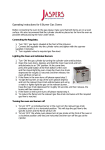
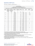
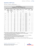
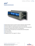
High temperature burners - Sealed Nozzles 3 - 11.1 - 5 E - i - 6/09 Specifications of Series “SN” Sealed Nozzles Size 3/4” -5 3/4” - 7 1” - 9 1-1/4” - 12 1-1/4” - 14 1-1/2” - 16 1-1/2” - 18 2” - 20 2” - 24 2-1/2” - 27 3” - 33 Orifice area Maximum capacity @ 20”wc [1] Minimum capacity @ 0.25” wc [2] KBtu/h KBtu/h 103 161 233 385 537 689 850 1170 1565 1834 3200 13 18 26 43 60 77 95 120 175 205 360 2 in 0.093 0.15 0.248 0.442 0.601 0.785 0.936 1.23 1.767 2.24 3.34 [1] Maximum capacity requires 20” wc mixture pressure [2] Minimum capacity at 0.25 “ wc . Note burner turndown is dependent on fuel/air ratio control and mixer performance. Data in this table are based on 100% mixture firing. The Sealed Nozzle burner is designed to operate at an on-ratio mixture throughout the entire capacity range. 10000 3 3" - 7 "-2 2- 1/24 2 2" - 0 2 2" 8 "-1 1- 1/2 6 "-1 /2 1 14 "-1 1- 1/4 - 12 " 1- 1/4 1000 Capacity (kBTU / h) 3 9 1" - 100 10 0 5 10 15 Mixture Pressure ( " wc) Pressures displayed are measured differentially from the nozzle inlet to the firing chamber w w w . m a x o n c o r p . c o m combustion systems for industry Maxon reserves the right to alter specifications and data without prior notice. © 2009 Copyright Maxon Corporation. All rights reserved. 20 3/4" 7 3/4" 5 High temperature burners - Sealed Nozzles 3 - 11.1 - 6 E - i - 6/09 Materials of construction 1 2 3 Item number 1 2 3 Burner part Nozzle Burner block Mounting frame Material Carbon steel Castable refractory Cast gray iron w w w . m a x o n c o r p . c o m combustion systems for industry Maxon reserves the right to alter specifications and data without prior notice. © 2009 Copyright Maxon Corporation. All rights reserved. High temperature burners - Sealed Nozzles 3 - 11.1 - 7 E - i - 6/09 Selection criteria Sealed Nozzle versions All MAXON burner nozzles are identified with a 3-part designation. This code identifies the type of nozzle, the inlet pipe size, and the main gas port diameter measured in 1/16ths of an inch. Type of nozzle SN Type of nozzle SN - Sealed Nozzle SNF - Sealed Nozzle with provision for flame safeguard device Inlet pipe size 3/4” Main gas port diameter 5 Inlet pipe size 3/4” 1” 1-1/4” 1-1/2” 2” 2-1/2” 3” Main gas port diameter 5 = 5/16” 7 = 7/16” 9 = 9/16” 12 = 3/4” 14 = 7/8” 16 = 1” 18 = 1-1/8” 30 = 1-1/4” 24 = 1-1/2” 27 = 1-11/16” 33 = 2-1/16” Mixture supply Sealed Nozzle burners require a full air/gas premixture from a premixing device. MAXON offers a wide variety of premixing equipment for optimal burner fuel supply: PREMIX® Blower Mixers Mixing Tubes & MULTI-RATIO® Mixers VENTITE™ Inspirators MG Mixing Tubes A complete burner nozzle system will also include gas train, proportioning and mixing equipment, combustion air supply and a combustion control panel. Contact MAXON for more information. Process temperature Standard burner block material is suitable for operating temperatures up to 2600°F . The maximum operating temperature limit may be downrated to 2400°F if the Sealed Nozzle Burner is operating under the following conditions: burner is installed in a furnace with fiber wall construction frequent cycling inducing thermal shock and stresses Optional refractory block materials are available to extend maximum operating temperature limits up to 3000°F (contact MAXON for more information.) Piloting and ignition All Sealed Nozzle assemblies include a pilot port tunnel and provision for mounting of a broad range of accessory pilots. NOTE: Every Sealed Nozzle burner must be ordered either with an appropriate pilot assembly or with optional pilot port cover kit. If a pilot assembly is not ordered, a pilot port cover kit must be used to prevent the possibility of flame and/or hot combustion gases escaping out of the burner’s “open” pilot port tunnel, or to prevent infiltration of secondary air on “un-piloted” installations. w w w . m a x o n c o r p . c o m combustion systems for industry Maxon reserves the right to alter specifications and data without prior notice. © 2009 Copyright Maxon Corporation. All rights reserved. 3 - 11.1 - 8 E - i - 6/09 High temperature burners - Sealed Nozzles Ratio control Air/fuel ratio control can be accomplished with MAXON MICRO-RATIO® valves and SMARTLINK® technology. Air/gas premixing equipment, such as a PREMIX® Blower Mixer, MULTI-RATIO® Mixer or “LG” Mixing Tube, may be used to provide thorough blending of air/gas mixture to MAXON Premix Burners. Any reference to a pressure must relate to the effective discharge area through which the volume of gas or air/gas premixture is passing. When selecting premixing equipment systems, the maximum and minimum mixture pressures must be evaluated relative to the quantity and/or size of the nozzle(s). The ratio between these two factors dictates the turndown capabilities of the overall system. Multiple nozzle combinations may be considered for a given heat release with a specific premixing device, but the total discharge areas of all the multiple nozzles must not exceed the effective discharge area of the specified single nozzle size. A minimum differential mixture pressure of +0.25” wc must be maintained to minimize the potential for backfiring. Typical ignition sequence Pre-purge of burner and installation, according to the applicable codes and the installation requirements. Combustion air control valve shall be in the minimum position to allow minimum combustion air flow to the burner. Pre-ignition (typically 2 s sparking in air). Open pilot gas and continue to spark the ignitor (typically 5 s). Stop sparking, continue to power the pilot gas valves and start flame check. Trip burner if no flame from here on. Check pilot flame stability (typical 5 s to prove stable pilot). Open main gas valves and allow enough time to have main gas in the burner (typical 5 s + time required to have main gas in the burner). Close the pilot gas valves. Release to modulation (allow modulation of the burner). Above sequence shall be completed to include all required safety checks during the start-up of the burner (process & burner safeties). Locate one pilot gas valve as close as possible to the pilot burner gas inlet to have fast ignition of the pilot burner. Flame supervision Series “SN” Sealed Nozzles (available in 3/4” through 1” sizes) consist of a threaded nozzle, cast iron frame and a refractory burner block. “SN” Sealed Nozzles do not include any provision for mounting a flame safeguard device. Series “SNF” Sealed Nozzles (available in 1-1/4” through 3” sizes) are the same as “SN” Sealed Nozzles, but incorporate a flame safeguard port through which a flame rod or a flame detector can be mounted. Sealed Nozzle burners can fire in any orientation, but the scanner manufacturer may impose limitations. Avoid orientations which might permit pilot and/or flame supervision ports to collect debris and/or condensation. Piping Flexible connections are recommended in all piping to reduce piping stresses and alignment/shifting problems. Excessive maintenance on the burner blocks and castings is frequently the result of external stresses and strains transmitted to the burner through the piping. On large installations, consider the use of flexible piping connectors to provide expansion in both length and alignment. Installation of such connectors at certain key spots in the air or gas manifolding can prevent damage to the burners from uneven thermal expansion. Fuels Sealed Nozzle burners operate on any fuel with heating values over 500 Btu/ft3. Avoid the use of fuels containing hydrogen over 5% by volume. Expected emissions Sealed Nozzle burners produce moderate levels of NOx through fuel/air premixing. With clean utility grade fuels, Sealed Nozzles can produce 20-30% less NOx than conventional nozzle mix burners. w w w . m a x o n c o r p . c o m combustion systems for industry Maxon reserves the right to alter specifications and data without prior notice. © 2009 Copyright Maxon Corporation. All rights reserved. High temperature burners - Sealed Nozzles 3 - 11.1 - 9 E - i - 6/09 Dimensions and weights 1 A F 2 A-A D 1) Flame detection port 3/4” NPT; bush to 1/4” NPT for flame rod B C M 2) Air/gas inlet 3) Optional flame rod 4) 10 mm spark ignitor included with a pressure pilot View A-A 5) 3/8” pilot gas connection 6) 3/8” pilot air connection 3 G S R 4 J N H J 6 O P 5 Dimensions in inches unless stated otherwise Burner size 3/4”-5, -7 1”-9 1-1/4”-12, -14 1-1/2”-16, -18 2”-20 2”-24 2-1/2”-27 3”-33 A B C D 2.44 .31 7.5 5 3.31 3.44 4.19 4.69 5.75 F [1] 3/4” 1” 1-1/4” 1-1/2” G H J 6.38 8.75 3.75 M --3.62 .38 9 7.5 2” 9 12.12 5.25 3.94 .5 9.5 9 2-1/2” 3” 11.5 13.88 6 3.68 [1] Available with NPT or ISO threads w w w . m a x o n c o r p . c o m combustion systems for industry Maxon reserves the right to alter specifications and data without prior notice. © 2009 Copyright Maxon Corporation. All rights reserved. N O 5 5 5 5 5 5 5 5 2 2 2 2 2 2 2 2 P R S .28 .88 5.12 .34 1 6.12 .41 1.25 --4.88 Weight lbs 31 31 31 58 59 68 59 79 High temperature burners - Sealed Nozzles 3 - 11.1 - 10 E - i - 6/09 Accessories Sealed port pressure pilot This pilot can be mounted directly onto the Sealed Nozzle burner pilot connection. It includes the spark ignitor and mounting gasket and is suitable for all burner sizes. 1 2 A 1) Pilot burner nozzle and mounting gasket 2) Spark ignitor 3 3) Sight glass 4) Gas adjusting needle valve 4 D C 5) Gas connection 3/8” NPT 6) Air connection 3/8” NPT 5 A 5.7 Dimensions in inches unless stated otherwise B C 3.8 4.4 6 B D 5.6 w w w . m a x o n c o r p . c o m combustion systems for industry Maxon reserves the right to alter specifications and data without prior notice. © 2009 Copyright Maxon Corporation. All rights reserved. High temperature burners - Sealed Nozzles 3 - 11.1 - 11 E - i - 6/09 Optional pilot port cover Optional pilot port cover must be used to seal pilot tunnel if no pilot is installed. (Order pilot port cover set, pilot assembly, and/or flame rod separately.) 1) Pilot port cover kit 1 Flame rod E D MAXON A = flame rod cut length without cooling tee B = flame rod cut length with cooling tee C = overall dimension before cutting D = length before cutting A and B C Burner size 3/4”-5, -7; 1”-9 1-1/4”-12, -14 1-1/2”-16, -18; 2”-20; 2”-24; 2-1/2”-27 3”-33 without cooling tee 3”-33 with cooling tee [3] Dimensions in inches unless stated otherwise A [1] B [2] C ------3.725 7.0 9.8 D --7.125 E --2.6 4.125 7.12 9.8 7.125 2.6 5.625 --- --8.62 9.8 14.8 7.125 12.0 2.6 2.8 [1] Without cooling tee [2] With cooling tee [3] When the flame rod is ordered with the nozzle, it is cut to correct length. If ordered separately, verify that it is cut to correct length (A or B in above table) w w w . m a x o n c o r p . c o m combustion systems for industry Maxon reserves the right to alter specifications and data without prior notice. © 2009 Copyright Maxon Corporation. All rights reserved. 3 - 11.1 - 12 E - i - 6/09 High temperature burners - Sealed Nozzles Spark ignitor 10 mm G 1 F H 1) 10 mm thread Dimensions in inches unless stated otherwise Burner size F G H All 2.81 0.25 0.125 Optional cooling tee set 1 2 1) Flame rod J 2) Cooling air tee Dimensions in inches unless specified otherwise Burner size All J 4.58 w w w . m a x o n c o r p . c o m combustion systems for industry Maxon reserves the right to alter specifications and data without prior notice. © 2009 Copyright Maxon Corporation. All rights reserved. High temperature burners - Sealed Nozzles 3 - 11.1 - 13 E - i - 6/09 Installation instructions for Sealed Nozzles Application requirements View port A view port to observe the burner flame is essential to inspect the flame aspect. Locate the view port downstream of the flame, looking back to the burner block. Make sure the complete flame can be evaluated. Support burner air and gas piping Sealed Nozzles shall not be used as support for the piping to the burner. Gas and air piping shall be supported in such a way that no additional loads will be created on the burner. Burner mounting flange loads Check the burner weight and reinforce the burner mounting flange or the combustion chamber/furnace back wall if necessary to take the complete burner weight. Installation instructions Storage of Sealed Nozzles Sealed Nozzles shall be stored dry (inside). Burner blocks have been cured carefully before shipment and shall be kept dry. Wetting of the blocks could result in premature failures. Handling of Sealed Nozzles Sealed Nozzles are shipped as complete units. Handle nozzles with care during unpacking, transport, lifting, and installation. Use proper equipment. Any impact on the burner could result in damage. Flange the burner to the installation Bolt the burner to the installation’s burner mounting flange. Use proper gasketing. Tighten the flange bolting with appropriate torque. Retighten all bolts after first firing and regularly after commissioning. w w w . m a x o n c o r p . c o m combustion systems for industry Maxon reserves the right to alter specifications and data without prior notice. © 2009 Copyright Maxon Corporation. All rights reserved. 3 - 11.1 - 14 E - i - 6/09 High temperature burners - Sealed Nozzles Burner mounting In a refractory wall, bolt the burner directly to the furnace shell as shown in Sketch 1 or, if there is no shell, use angle irons extended between structural supports of the furnace wall as shown in Sketch 2. In either case, size the opening in your refractory wall to give a 3” gap around the burner, then stuff the gap with castable refractory, following manufacturer’s instructions. Allow sufficient dry-out time before firing the burner, and cure slowly at start-up. Slotted holes in the burner mounting frame are intended to allow for lateral expansion of the furnace. Tighten the burner mounting bolts only enough to hold the burner in position. Sketch 1 5 Sketch 2 1 6 1) Furnace wall 2) Castable refractory material 4 1 4 3) Pilot 4) Mounting frame 5) Furnace shell 6) Angle iron 3 3 2 2 w w w . m a x o n c o r p . c o m combustion systems for industry Maxon reserves the right to alter specifications and data without prior notice. © 2009 Copyright Maxon Corporation. All rights reserved. High temperature burners - Sealed Nozzles 3 - 11.1 - 15 E - i - 6/09 Block replacement If the refractory block of your Sealed Nozzle burner requires replacement, MAXON can supply replacement block and frame subassemblies. To install a new block and frame assembly: Shut off the system and allow to cool. Disconnect the piping and remove the Sealed Nozzle burner from the installation. Unscrew the bolts which fasten the nozzle body to the mounting frame, set aside and remove the burner body (tapping lightly if necessary to break bond). Clean all old refractory from the main body to insure a proper seal when re-assembling. Prepare a refractory cement mixture. Apply a generous coating of the refractory cement to those surfaces of the new block which will mate with the burner main body when it is installed. Put the main body into position and bolt finger-tight. Remove any excess refractory cement that is forced out between the body and the burner block. Tighten the nozzle body firmly into position and clean the throat with a narrow, wet brush to insure a smooth path for air and gas. Allow the re-assembled burner to stand at least 48 hours so that refractory cement will set. Failure to do so may result in a weak bond and early deterioration. Reinstall the burner, following the installation instructions. Dry the refractory thoroughly by running the burner at low fire for at least 15 minutes. Reconnect all controls, etc., restoring the burner to service following manufacturer’s instructions. 2 1 1) Nozzle body 2) Refractory cement seal 3) Burner block 4) Mounting frame 5 5) Air/gas premixture from mixing device 3 4 w w w . m a x o n c o r p . c o m combustion systems for industry Maxon reserves the right to alter specifications and data without prior notice. © 2009 Copyright Maxon Corporation. All rights reserved. High temperature burners - Sealed Nozzles 3 - 11.1 - 16 E - i - 6/09 Start-up instructions for Sealed Nozzles Instructions provided by the company or individual responsible for the manufacture and/or overall installation of a complete system incorporating MAXON burners take precedence over the installation and operating instructions provided by MAXON. If any of the instructions provided by MAXON are in conflict with local codes or regulations, please contact MAXON before initial start-up of equipment. Read the combustion system manual carefully before initiating the start-up and adjustment procedure. Verify that all of the equipment associated with and necessary to the safe operation of the burner system has been installed correctly, that all pre-commissioning checks have been carried out successfully and that all safety related aspects of the installation are properly addressed. Initial adjustment and light-off should be undertaken only by a trained commissioning engineer. First firing or restart after shut-down During first start-up of the burner, and after every longer installation shut-down, the temperature rise shall be limited. Allow the burner to fire on low fire for some time to allow the parts to heat up slowly. Checks during and after start-up During and after start-up, check the integrity of the system. Check all bolted connections after first firing (first time on temperature) and retighten if necessary. Pilot ignition Adjust pilot air flow and pilot gas regulator to correct set point before pilot ignition attempt. Turn the adjustable orifice screw out (counter-clockwise) several turns from its fully seated position. Refine during lighting of the pilot to a yellow/blue flame and/or the strongest flame signal. Main burner ignition Set the correct gas flow for burner minimum capacity before attempt of main burner ignition. Verify that the minimum air differential pressure exceeds 0.25” wc to prevent flashback. After ignition of the main burner, allow some time on minimum capacity to allow the burner parts to heat up slowly. Adjust air/gas ratio, set maximum capacity Once the main flame is ignited, adjust air/gas ratio of the burner to have the required combustion quality and slowly increase capacity. (Do not increase capacity too fast to avoid damage to burner parts or furnace due to excessive temperature gradient.) w w w . m a x o n c o r p . c o m combustion systems for industry Maxon reserves the right to alter specifications and data without prior notice. © 2009 Copyright Maxon Corporation. All rights reserved. High temperature burners - Sealed Nozzles 3 - 11.1 - 17 E - i - 6/09 Maintenance and inspection Safety requirements Regular inspection, testing, and recalibration of combustion equipment according to the user manual is an integral part of its safety. Inspection activities and frequencies shall be carried out as specified in the user manual. Perform the following activities at least annually as part of a recommended preventative maintenance routine: Inspect burner parts for wear and oxidation. Check for nozzle plugging. Check that required nozzle clearance is maintained. Inspect associated control instruments and devices for function with particular attention to all safety interlocks. Visual inspections Regular visual inspection of all connections (air and gas mixture piping to the burner, fixation of the burner on the installation) and burner flame shape and aspect are essential for safe operation. Spare parts Keep local stock of spark ignitor and flame detection device. It is not recommended to keep local stock of other burner parts. Consult user manual for burner spare parts and system accessories. w w w . m a x o n c o r p . c o m combustion systems for industry Maxon reserves the right to alter specifications and data without prior notice. © 2009 Copyright Maxon Corporation. All rights reserved.