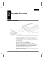
1
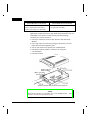
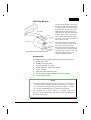
EasyPack®
and
EasyPack®/S
8051/8052
In-Circuit Emulator
Up and Running
In 30 Minutes!
MICETEK INTERNATIONAL INC.
Doc. No. 001-000012
Second Edition
March, 2000
Trademark Acknowledgments
EasyPack is a registered trademark of Microtek International.
SLD is a trademark of Microtek International.
IBM is a registered trademark and PS/2 is a trademark of IBM.
Microsoft, MS, MS-DOS, and Windows are registered trademarks of Microsoft
Corporation.
Intel is a registered trademark and Intel386SX is a trademark of Intel Corporation.
Philips is a trademark of Philips Semiconductors
2500AD is a trademark of 2500AD Software, Incorporated.
IAR is a trademark of IAR Systems AB.
Franklin is a trademark of Franklin Software, Inc.
Keil is a trademark of Keil Elektronik GmbH
BSO/Tasking is a trademark of Boston System Office.
CodeCruiser is trademark of Micetek.
Doc. # 001-000012 (Second Edition)
2000 MICETEK INTERNATIONAL INC.
All Rights Reserved
Printed in Taiwan, 03/2000
The contents of this manual are subject to change without notice. MICETEK International
Inc., assumes no responsibility for errors that may appear in this manual. MICETEK
makes no commitment to update, nor to keep current, the information contained in this
manual. Nothing herein shall be construed as a recommendation to use any product in
violation of existing patents or other rights of third parties.
NO PART OF THE CODECRUISER AND OF THIS MANUAL MAY BE
REPRODUCED OR TRANSMITTED IN ANY FORM OR BY ANY MEANS WITHOUT
THE EXPRESS WRITTEN PERMISSION OF MICETEK.
MICETEK INTERNATIONAL INC.
MICETEK
4F, Building 14, No.470 Guiping RD.
Shanghai 200233, P.R.C.
Voice : +86 21 6495-4008
Fax
: +86 21 6485-3259
E-mail : [email protected]
MICETEK
7F-1, #237, Sec.1, Wu Chuan West Road,
Taichung, Taiwan, 403
Voice : +886 4 378-6288
Fax
: +886 4 378-6289
E-mail : [email protected]
Contents • iii
C
ontents
1 Introduction
1
Overview ............................................................................................................................ 1
Related Publications and Cross-References ........................................................................ 1
Registering.......................................................................................................................... 2
How to Contact MICETEK ................................................................................................ 2
2 Emulator Overview
5
What You Should Get......................................................................................................... 5
EasyPack®(/S) 8052 Main Module........................................................................ 5
ICE Probe Module................................................................................................. 7
Accessories ........................................................................................................... 7
Features .............................................................................................................................. 8
Supported Targets ................................................................................................. 8
System Clock......................................................................................................... 8
Overlay Memory ................................................................................................... 9
Bank Switch (for EasyPack®/S 8052F only)......................................................... 9
Breakpoints ........................................................................................................... 9
Complex Event/Trigger ......................................................................................... 9
Real Time Trace Buffer....................................................................................... 10
Non-Intrusive Execution Control......................................................................... 10
Execution Time Measurement ............................................................................. 10
External Hardware Sync Interface ...................................................................... 10
Target Memory Retention ................................................................................... 10
Mapped Memory Retention................................................................................. 10
Trigger Constructs............................................................................................... 10
Stand-Alone Emulation ....................................................................................... 11
Communication Ports .......................................................................................... 11
Emulator Operation Requirements.................................................................................... 11
Power .................................................................................................................. 11
Environment........................................................................................................ 11
Emulator Weight and Dimensions..................................................................................... 11
Main Module....................................................................................................... 11
EasyPack(/S) 8051/52 Up&Running
iv • Contents
3 Hardware Installation and Setup
13
Overview ...........................................................................................................................13
Checking the Environmental Conditions............................................................................13
Protecting the Emulator from Electrostatic Discharge (ESD) ..............................13
Connecting EasyPack®(/S) 8052F to Host Computer.........................................................14
Connecting with Desktop PC Via Printer Port .....................................................14
Connecting with Notebook PC Via Printer Port ...................................................15
Connecting with Desktop PC Via Serial Port.......................................................15
Connecting with Notebook PC Via Serial Port.....................................................16
Defining Memory Size with Bank Switch Jumpers (for EasyPack/S only)..........17
Connecting EasyPack®(/S) 8051/52 Probe Module with Target ........................................19
Connecting Probe Module to PLCC Type Target Socket .....................................21
Defining Port 3 Function (I/O or RD / WR ) .......................................................21
Null-Target Installation for Stand-Alone Operation ..........................................................22
Null-Target Board Mini-Jumper (X1) Setup........................................................22
Connecting EasyPack®(/S) with the External Signal Cable ...............................................23
Applying Power to the System...........................................................................................24
Hardware Reset .................................................................................................................25
Cold Reset............................................................................................................25
Warm Reset .........................................................................................................25
4 Application and Engineering Notes
27
Overview ...........................................................................................................................27
General ..............................................................................................................................27
When Emulating 8051/8052 Target...................................................................................27
When Emulating 8031/8032 Target...................................................................................28
Appendix A
Target Interface Diagram
29
Interface Diagram for 8031/8032 ......................................................................................29
Interface Diagram for 8051/8052 ......................................................................................31
Interface Diagram for 80C154/80C51FA/8344.................................................................33
Interface Diagram for 87C652...........................................................................................35
Contents
iii
Index
31
EasyPack(/S) 8051/52 Up&Running
Chapter 1 • 1
1
Introduction
Overview
This manual will get you acquainted with the features and hardware
architecture of EasyPack 8052F and EasyPack/S 8052F in-circuit
emulators (see Chapter 2 Emulator Overview for the comparison
between the two configuration of emulators). The following shows
how the topics are arranged in this manual:
Chapter
Contents
Ë Emulator Overview
Describes the EasyPack and EasyPack/S
emulator main modules and parts. Lists the
emulator features, dimensions, and weight.
Ì Hardware Installation Describes emulator interface with host system.
and Setup
Í Application and
Engineering Notes
Appendix [A] Target
Interface Diagrams
Explains how to plug the emulator probe
module to target for emulation and to null target
for stand-alone operation. Communication and
emulation memory size setups are also
discussed in this chapter.
Describes the limitations and important
engineering notes that you should be aware of
about the current version of the EasyPack and
EasyPack/S development system.
Provides circuit guides for proper connection of
your target with the EasyPack or EasyPack/S
emulation processor.
Related Publications and Cross-References
• See the User's Guide for the Microsoft Windows Operating System
for more information on using Windows, Notepad, and Macro
Recorder.
EasyPack(/S) 8051/52 Up&Running
Introduction
2 • Chapter 1
• See the pertinent Processor User's Manual for information on the
target processor you are using.
• See the manual that came with the compiler you are using.
Registering
Be sure to complete and return the enclosed registration card so that
MICETEK can provide you with technical support and keep you
informed of new product developments.
How to Contact MICETEK
As a MICETEK customer, you can call MICETEK technical support
for help with an emulator problem during your warranty period. To
register for this support, be sure to fill out and mail in the registration
card that came with the emulator.
If you have a question about debug software, try to find the answer in
the manual or in on-line Help. If you cannot find the answer, contact
our Customer Support Department at any of the following sites:
Before you call, please read the EasyPack Emulator Problem Report
Form that came with the emulator. The form is also included in
README.TXT, installed in the debug software directory on your hard
disk.
Before you call, please read the EasyPack Emulator Problem Report
Form that came with the emulator.
When you call, you should be at your computer with the EasyPack and
debug software running.
Introduction
EasyPack(/S) 8051/52 Up&Running
Chapter 1 • 3
Micetek
Shanghai, PRC
Voice
: +86 21 6495-4008
Monday through Friday from
9 AM to 5 PM, Beijing Time.
FAX
: +86 21 6485-3259
24 hours
Email
: [email protected]
24 hours
Micetek
TaiChung, Taiwan
Voice
: +886 4 378-6288
Monday through Friday from
9 AM to 5 PM, Taiwan Time.
FAX
: +886 4 378-6289
24 hours
Email
: [email protected]
24 hours
For getting the latest information, please visit our web page:
http: //www.micetek.com
EasyPack(/S) 8051/52 Up&Running
Introduction
Chapter 2 • 5
2
Emulator Overview
What You Should Get
EasyPack(/S) 8052F Main Module and 8051/52 Probe Module Hardware Overview
The EasyPack or EasyPack/S development system comprises of the
Main Module and the ICE Probe Module. Their components are
common except for the model of the emulation control board installed
in the Main Module.
EasyPack®(/S) 8052 Main Module
The EasyPack and EasyPack/S 8052 Family Main Module is
applicable to all standard models of EasyPack and EasyPack/S series
ICE Probe Modules including 8051/52. It houses the Emulation
Control Board (ECBIIS-8052 for EasyPack/S 8052F or ECBIISA8052 for EasyPack 8052F) and the power supply.
The table below shows how features differ between EasyPack/S 8052F
and EasyPack 8052F emulators.
EasyPack(/S) 8051/52 Up&Running
Emulator Overview
6 • Chapter 2
EasyPack/S 8052F
EasyPack 8052F
(with ECBIIS-8052 Control Board)
(with ECBIISA-8052 Control Board)
Bank Switch Function or emulation
memory augmentation from 64K to
320K bytes (program 256, data 64K)
Fixed 128K emulation memory
(program 64K, data 64K)
The ECBIISA/S-8052 performs the emulation control and general
application emulation processes (plus bank switch function in the case
of ECBIIS). It houses the overlay memory and the following
connectors for various interfaces:
• One micro connectors for ICE cable interface with ICE Probe
Module.
• One 9-pin connector for External Trigger Out (ETO), trace bits
input and external breakpoint signal.
• One 25-pin connector for printer port communication.
• One RS-232 phone jack RJ11 connector for serial port
communication.
• One Reset button.
EasyPack(/S) 8052F Main Module Hardware Breakdown
NOTE
Bank Switch Jumper is available only with ECBIIS board. This
board is installed on EasyPack/S only.
Emulator Overview
EasyPack(/S) 8051/52 Up&Running
Chapter 2 • 7
ICE Probe Module
The ICE Probe Module connects the
Easy-Pack to the Null-Target Board
or a target system. It has two layers
of mini-board. The top layer is the
EPH-52F board which houses the
emulation CPU and part of the timesensitive “glue” logic. The bottom
layer or EPL-52F board also houses
part of the “glue” logic in addition to
target plug-in socket.
The Null-Target Board provides
clock source when it connects with
the ICE Probe Module during
EasyPack stand-alone operation. It
is removed before the probe module
is plugged into a target system. The
Null-Target Board power cord
connects to EPH for power.
8051/52 ICE Probe Module Breakdown
Accessories
A complete EasyPack package also includes the following items:
a) An AC power cable
b) An MS-PCX 25-pin cable
c) A 9-pin connector trace cable
d) An EasyPack "Up & Running" manual
e) A User’s Guide
f) A RS-232 Cable with RJ11 jacks
g) Two (9 and 25-pin) RJ11 adapters to connect with host
h) A set of debug software
NOTE
1. An optional DIP to PLCC target socket adapter (see Section on
“Connecting Probe Module to PLCC Type Target” in Chapter
3) is available and shipped through separate request. Contact
your nearest MICETEK dealer for detailed information.
2. For complete list of items which are provided with every
shipment, refer to the Package Checklist packed and attached to
the EasyPack package.
EasyPack(/S) 8051/52 Up&Running
Emulator Overview
8 • Chapter 2
Features
Supported Targets
Emulation CPU
8031/32
8x31/32
8051/52
8x51/52
80C31/32
8xC31/32
Vendor
80C51/52
8xC51/52
SC8xC51
AT89C51/52
Philips, Intel, MHS,
Siemens, OKI,
Atmel, Temic,
Mosel
8031A-20
MSU2031
SAB-C501G-L40/24P
80C51FA/FB/FC
W78C31/2B
Winbond
8344
Intel
8xC51FA/FB/FC
Philips
8xC51RA/RB/RC
80154, 80C154
Intel, MHS, OKI
8xC652/4
Philips, Temic
NOTE
EasyPack 8051/52 is shipped with 87C52UBPN emulation CPU.
Probe Module is shipped with a DIP package target probe. A
DIP to PLCC adapter is available (under separate order) to
accommodate PLCC targets.
Contact your MICETEK Sales Office or Technical Support (see
contact information on page 3 of Chapter 1) for further
information.
System Clock
Provides frequency measurement calculation for time stamping timing.
Emulator Overview
EasyPack(/S) 8051/52 Up&Running
Chapter 2 • 9
Overlay Memory
EasyPack
• 128KB emulation memory
(64KB program memory and
64KB data memory)
EasyPack/S
• 320KB emulation memory
(256KB program memory and
64KB data memory)
• with following attributes:
• with following attributes:
- Overlay (EasyPack) read/write
- Overlay (EasyPack/S) read/write
- Overlay (EasyPack) read
- Overlay (EasyPack/S) read only
only
- Target (target) read/write
- Target (target) read/write
- Target (target) read only
- Target (target) read only
- Guard (non-existence)
- Guard (non-existence)
- Combination read/write
- Combination read/write
- Combination read only
- Combination read only
Bank Switch (for EasyPack®/S 8052F only)
Bank switching of emulation memory from 64K to 256K bytes
maximum. Switching of desired memory size is done by repositioning
of jumpers on the ECBIIS board.
Breakpoints
Real-time hardware (Events) breakpoints. This Includes—
• 2
Multiple Setting Bus Breakpoints
• 1
External Trigger Input Breakpoint
• 64K Hardware Execution Breakpoints for EasyPack
- or 256K Hardware Execution Breakpoints when using the Bank
Switch for EasyPack/S
Complex Event/Trigger
• One External Trigger Input (ETI) and One External Trigger Output
(ETO) for device synchronization.
• Up to 2 Trigger Levels, each level may be a single event or any
logical construction of Event1, Event2, and Event3.
• Event Count providing matched count triggering.
• Trace collection with flexible trigger supporting Forward,
Backward, Center, and delay trigger trace.
EasyPack(/S) 8051/52 Up&Running
Emulator Overview
10 • Chapter 2
Real Time Trace Buffer
• 32K frames deep and 40 bits wide, including 16 bits address, 8 bits
data, 3 bits status, 5 bits external trace points and 8 bits port status
(port selectable).
• Supports trace ON/OFF operation.
• Supports hardware trace qualifiers.
Non-Intrusive Execution Control
• Single Step/Step Over in source or assemble levels.
• Cycle step displaying address, data cycle status, port status, and
external trace bit status.
Execution Time Measurement
Measurable by self-contained timer (maximum time length is 36.4
hours with 1µsec timebase).
External Hardware Sync Interface
External Trigger Out (ETO) port provides an output EVENT
TRIGGER match signal (active high when Event3 matched; negated
when trigger level matched).
Target Memory Retention
Target processor can retain its entire memory and I/O space.
Mapped Memory Retention
User defined emulation memory mapping and information, as well as
window layout, are saved to host by clicking on the Save button. They
are retrieved by clicking the Restore button.
Trigger Constructs
Powerful Trigger Constructs. The trigger conditions are composed of
up to 2 “trigger-level” where each level specifies an event combination.
Each level may be a single event or a logic combination of Event1,
Event2, and Event3 with AND/OR as operators.
Emulator Overview
EasyPack(/S) 8051/52 Up&Running
Chapter 2 • 11
Stand-Alone Emulation
• Supports stand-alone emulation with 22.1184MHz crystal sourced
from the bundled null-target device.
Communication Ports
• One 8-bit printer port (25-pin twisted pair) allows your host PC or
notebook to interface with EasyPack(/S) through printer port.
• One RJ-11 phone jack connector allows your host PC or notebook to
interface with EasyPack/S through serial port.
Emulator Operation Requirements
Power
• 90 to 264VAC (Auto-range);
• 50 to 60Hz;
• Consumption: 37W maximum;
• Fuse rating: 1.5A/250V slow blow
Environment
• Operating Temp: 0° to 50° C (32° to 122° F)
• Storage Temp: -10° to 65° C (14° to 149° F)
• Relative Humidity: 20 to 80%
Emulator Weight and Dimensions
Main Module
• Length: 27cm (10.6 in.)
• Width: 23cm (9.0 in.)
• Height: 6cm (2.4 in.)
• Net weight (including Probe module): 1.5kg (3.31 lb.)
EasyPack(/S) 8051/52 Up&Running
Emulator Overview
Chapter 3 • 13
3
Hardware Installation and Setup
Overview
This chapter guides you on how to:
• Check the EasyPack working environment.
• Connect the EasyPack to host and ICE Probe Module to target.
• Setup printer and serial ports.
• Define memory size with bank switch (EasyPack/S Only).
• Perform Null-Target installation.
• Connect the EasyPack with the External Signal Cable.
Checking the Environmental Conditions
The emulator resides in the same environment as your host computer.
Avoid excessive heat. Leave a few inches around the main chassis for
air circulation. Use good grounding practices. Locate the emulator
away from sources of interference.
Characteristic
Operating Parameter
Ambient temperature
0 - 50° C (32 - 122° F)
Ambient humidity
80% maximum relative humidity, non-condensing
Protecting the Emulator from Electrostatic
Discharge (ESD)
The I/O circuitry of the Probe Module can be damaged by excessive
ESD. To protect your probe from ESD:
• Be sure the chassis, host, and workbench are properly grounded
before applying power.
• Work in a static-free work environment.
• Use a wriststrap attached to ground while handling the probe.
• Avoid touching the exposed connector on the probe tip when you are
not properly grounded.
EasyPack(/S) 8051/52 Up&Running
Hardware Installation and Setup
14 • Chapter 3
Connecting EasyPack®(/S) 8052F to Host Computer
Before connecting, make sure that you have the following minimum
host configuration:
• An Intel386DX-or later (including Pentium-based) PC, or 100%
compatible system
• 4 MB (or greater) of RAM
• 8 MB of available disk space for debug software
• 9.5-MB (or greater) permanent swapfile
• VGA or Super VGA color monitor
• Windows 95, 98 or NT.
Connecting with Desktop PC Via Printer Port
Connecting EasyPack(/S) System to Desktop PC Printer Port
Hardware Installation and Setup
EasyPack(/S) 8051/52 Up&Running
Chapter 3 • 15
Connecting with Notebook PC Via Printer Port
Connecting EasyPack(/S) System to Notebook Printer Port
Connecting with Desktop PC Via Serial Port
Connecting EasyPack(/S) System to Desktop PC Serial Port
EasyPack(/S) 8051/52 Up&Running
Hardware Installation and Setup
16 • Chapter 3
Connecting with Notebook PC Via Serial Port
Connecting EasyPack(/S) System to Notebook PC Serial Port
Hardware Installation and Setup
EasyPack(/S) 8051/52 Up&Running
Chapter 3 • 17
Defining Memory Size with Bank Switch Jumpers
(for EasyPack/S only)
The Bank Switch feature allows you to define either 64K (no bank in
use), or 128K (2 bank in use), or 256K (4 bank in use) bytes of
emulation memory to accommodate the size of the debugging program
to be downloaded.
Bank switching is accomplish by closing appropriate pins between
banks or mini-jumpers J11, J12,
and J13, located on the ECBIIS
Emulation Control Board. Their
pin assignments are shown
below.
Bank Switch Jumpers J11. J12, and J13 Location
8
7 6
5 4
3
2 1
0
J11
° ° ° ° ° ° ° ° °
Pins 0-7 are connected to A16 control bit.
J12
° ° ° ° ° ° ° ° °
Pins 0-7 represent P1 or P3. Pin 8 is closed for
2 Bank (128K Emulation Memory) selection.
J13
° ° ° ° ° ° ° ° °
Pins 0-7 are connected to A17. Pin 8 is closed
for 4 Bank (256K Emulation Memory) selection.
Bank Switch Jumpers Pin Assignment
Setting for 64K Emulation Memory
No jumper is required when single bank selection is made or when
defining for 64K emulation memory.
For 64K emulation
memory, no jumper
required or position
jumper as shown
EasyPack(/S) 8051/52 Up&Running
J11
J12
J13
° ° ° ° ° ° ° ° °
° ° ° ° ° ° ° ° °
° ° ° ° ° ° ° ° °
Don’ t care for
control bit selection
Hardware Installation and Setup
18 • Chapter 3
Setting for 128K Emulation Memory
Two bank selection is made when defining for 128K emulation
memory. In the example below, Pins 0 & 8 of Jumper11 are closed
across bank with Pins 0 & 8 of Jumper 12 respectively using P10
Signal.
Jumper position for 128K
Jumper at Bit 0 position
for A16 control bit
emulation memory
JUMPER PINS
JUMPER
POSITION
J11
J12
J13
8
0~7
J11
J12
Close
Close one for
A16 control bit
J13
°
°
°
° ° ° ° ° ° ° °
° ° ° ° ° ° ° °
° ° ° ° ° ° ° °
Setting for 256K Emulation Memory
Four bank selection is made when defining for 256K emulation
memory. In the example below, Pins 0, 1, & 8 of Jumper12 are closed
across bank with Pins 0, 1, & 8 of Jumper 13 respectively using P10
and P11 Signals.
Jumper at Bit 0 & 1 position
for A16 & A17 control bits
respectively
Jumper position for 256K
emulation memory
JUMPER
POSITION
J11
J12
J13
Hardware Installation and Setup
JUMPER PINS
8
Close
0~7
J11
Close two separately
for A16 and A17
control bit
J12
J13
° ° ° ° ° ° ° ° °
° ° ° ° ° ° ° ° °
° ° ° ° ° ° ° ° °
EasyPack(/S) 8051/52 Up&Running
Chapter 3 • 19
Connecting EasyPack®(/S) 8051/52 Probe Module with Target
NOTE
See Appendix A for the target interface diagram.
To prevent possible damage to equipment, ensure to comply
with the following:
1. The ICE Probe Modules for 8051/52 are NOT
interchangeable and should be used only with 8051/52
supported targets (see section on “Features” in Chapter 2).
2. Ensure that the pin numbers of both the Probe Module and
that of the target CPU socket (or CPU chip) are properly
aligned before plugging them together.
3 Check to confirm that the ICE Probe cable is firmly plugged
into their respective 80-pin connectors on EasyPack (/S)
Module.
Depending on the type (ROMless, ROM, or EPROM) of the target
CPU under emulation, the EasyPack(/S) Probe Module needs to be
initially reconfigured into single-board (EPH-52F only) or doubleboard (both EPH-52F and EPL-52F) module for proper operation as
illustrated and categorized below.
EasyPack(/S) 8051/52 Up&Running
Hardware Installation and Setup
20 • Chapter 3
Single-Board Probe Module
Double-Board Probe Module
Use Single-Board Probe Module with
following ROMless targets:
Use Double-Board Probe Module with
following ROM/EPROM targets:
8031
(ROMless NMOS)
8051
(ROM NMOS)
8032
(ROMless NMOS)
8052
(ROM NMOS)
80C31
(ROMless CMOS)
8751
(EPROM NMOS)
80C32
(ROMless CMOS)
8752
(EPROM NMOS)
8344
(ROMless NMOS)
80C51
(ROM CMOS)
80C51FA/FB/FC (ROMless CMOS)
87C51FA/FB/FC (EPROM CMOS)
80C154
(ROMless CMOS)
80C52
(ROM CMOS)
80C320
(ROMless CMOS)
87C51
(EPROM CMOS)
80C652
(ROMless CMOS)
87C52
(EPROM CMOS)
W78C31B-40
(ROMless CMOS)
83C652
(ROM CMOS)
W78C32B-40
(ROMless CMOS)
83C654
(ROM CMOS)
87C652
(EPROM CMOS)
87C654
(EPROM CMOS)
With the Null-Target board removed from the bottom of the probe,
proceed to carefully plug the probe module into the target
Hardware Installation and Setup
EasyPack(/S) 8051/52 Up&Running
Chapter 3 • 21
Connecting Probe Module to PLCC Type Target
Socket
Using Adapter to Connect Probe Module with
PLCC Type Target
The ICE Probe Module is
shipped with a DIP type
target probe which plugs
directly to target with DIP
type CPU socket. If your
target system is equipped
with a PLCC type CPU
socket, the optional DIP to
PLCC socket adapter (EPPLCC-APT as shown in
the figure at left) should be
initially attached to the
bottom of the ICE probe
before inserting the ICE
Probe Module into the
PLCC type CPU socket.
Defining Port 3 Function (I/O or RD / WR )
Assign required Port 3 pin function (I/O or RD / WR ) by positioning
the mini-jumpers X4 and X5 located on top of the ICE Probe Module
or as indicated in the above figure.
Position mini-jumper according to the desired function as directed in
the following table:
JUMPER
POSITION
JUMPER PINS
3
2
1
SIGNAL
FUNCTION
X4
Close
I/O (P3.7)
X5
Close
I/O (P3.6)
Port Signal (I/O) Selection
JUMPER
POSITION
JUMPER PINS
3
2
1
SIGNAL
FUNCTION
X4
Close
RD
X5
Close
WR
Port Signal (I/O or RD / WR ) Selection
EasyPack(/S) 8051/52 Up&Running
Hardware Installation and Setup
22 • Chapter 3
Null-Target Installation for Stand-Alone Operation
If not already installed, the factory provided null-target board must be
attached to the probe module when performing stand-alone operation.
Install null-target board as follows:
1. Install the probe module socket into the null-target board.
2. Connect the null-target power cord connector to its power source on
EPH-52F board of the ICE Probe Module as indicated in the figure
below.
Mating Null-Target Board with the ICE Probe
Null-Target Board Mini-Jumper (X1) Setup
With the null-target board pulled out from the ICE Probe Module,
position mini-jumpers X1 (see figure above) to correspond with the
emulation CPU series installed, or as indicated in the following table.
Jumper
Position
J1
Hardware Installation and Setup
Jumper Pins
GND
EA
VCC
Close
Close
Emulation
CPU
8051 Series
8031 Series
EasyPack(/S) 8051/52 Up&Running
Chapter 3 • 23
Connecting EasyPack®(/S) with the External Signal Cable
The EasyPack external signal cable is utilized for recording external
signals during trace operations. To monitor these signals, attach the 9pin female connector of the cable to its corresponding male con-nector
at the left side panel of the EasyPack Main Module or as shown in the
following illustration.
Connecting External Signal Cable
The 9-pin connector pin assignments are as follows:
9-Pin External Signal Cable Connector
EasyPack(/S) 8051/52 Up&Running
Hardware Installation and Setup
24 • Chapter 3
PIN #
BIT
FUNCTIONS
1
Input
Event 3 detects this signal to stop emulation
2
GND
Signal ground
3
Output
4
GND
5
0
6
1
7
2
8
3
9
4
A low pulse is sent out when Event 1 is matched
Signal ground
These bits are recorded to trace buffer
Applying Power to the System
WARNING
Check to ensure compliance to proper operating environment
(temperature, humidity, etc.), grounding and electrostatic
discharge protection requirements specified for EasyPack and
for delicate electronic equipment in general. Also ensure all AC
power terminals are properly aligned before plugging them to
power source.
You must refer to the “Application and Engineering Notes” in
Chapter 5 before performing emulation with your EasyPack(/S).
The recommended power up sequence is to apply power to target
system first, and then to either EasyPack(/S) or host. When turning
power off, EasyPack(/S) is turned off first and target system the last.
At power-up, the EasyPack(/S) will automatically check to determine
whether power is supplied to the target. At the same time, the amber
colored LED on top of the EasyPack(/S) Module illuminates.
Hardware Installation and Setup
EasyPack(/S) 8051/52 Up&Running
Chapter 3 • 25
Hardware Reset
The EasyPack may be reset with either of the following methods:
Cold Reset
By turning the power switch off and then on again. Be sure to wait a
few seconds before restoring power to the system.
Warm Reset
Hardware Warm Reset Button
By momentarily pressing the manual RESET button
(located on the side panel of EasyPack and adjacent to
external signal cable connector as shown in the figure at
right). The warm reset button is used to reset the control
and emulation processor without affecting the contents of
overlay memory.
Before pressing RESET button, quit the debug software and
reinitiate debugger.
EasyPack(/S) 8051/52 Up&Running
Hardware Installation and Setup
Chapter 4 • 27
4
Application and
Engineering Notes
Overview
This chapter provides important procedures you must follow for proper
and stable operation of EasyPack(/S) 8052F. It offers precautions to
difficulties you may likely encounter while performing emulation.
General
1. To protect your equipment from possible damage, always apply
power to your target first before EasyPack(/S) is powered on.
2. Pins 1 and 2 of the mini-jumper X3 (located on top of the ICE Probe
Module) should be in open position when NMOS controller with
clock source is used on target. Otherwise, it should remain closed
(default position).
When Emulating 8051/8052 Target
When emulating 8051/8052 (or 80C51/80C52) target, take note of the
following:
1. The use Philips 80C32UBPN as the emulation processor is highly
recommended.
2. The Philips 80C32UBPN is a commercial processor. When this
processor is used as the emulation processor, it can support 33MHz
maximum emulation speed.
CAUTION
Use of other CPU's as emulation CPU, may not produce the
desired emulation speed and results.
3. The ICE Probe Module lower board (EPL-52F) must be installed.
EasyPack(/S) 8051/52 Up&Running
Application and Engineering Notes
28 • Chapter 4
When Emulating 8031/8032 Target
When emulating 8031/8032 (or 80C31/80C32) target, take note of the
following:
1. 8031/8032 (or 80C31/80C32) from any vendor may be used as the
emulation processor.
2. The supported maximum speed of the emulation CPU (as of current
EasyPack version) is 40MHz.
3. The lower board (EPL-52F) must be removed from ICE Probe
Module.
4. When memory is mapped to “Internal” attribute while data memory
exists on target, set both mini-jumpers X4 and X5 on top of the
Probe Module to either RD & WR position, or to I/O (default)
position. See Section on “Defining Port 3 Function” in Chapter 3.
Application and Engineering Notes
EasyPack(/S) 8051/52 Up&Running
Appendix A • 29
A
Target Interface Diagram
Interface Diagram for 8031/8032
(see other side of this page)
EasyPack(/S) 8051/52 Up&Running
Target Interface Diagram
30 • Appendix A
Target Interface Diagram
EasyPack(/S) 8051/52 Up&Running
Appendix A • 31
Interface Diagram for 8051/8052
(see other side of this page)
EasyPack(/S) 8051/52 Up&Running
Target Interface Diagram
32 • Appendix A
Target Interface Diagram
EasyPack(/S) 8051/52 Up&Running
Appendix A • 33
Interface Diagram for 80C154/80C51FA/8344
(see other side of this page)
EasyPack(/S) 8051/52 Up&Running
Target Interface Diagram
34 • Appendix A
Target Interface Diagram
EasyPack(/S) 8051/52 Up&Running
Appendix A • 35
Interface Diagram for 87C652
(see other side of this page)
EasyPack(/S) 8051/52 Up&Running
Target Interface Diagram
36 • Appendix A
Target Interface Diagram
EasyPack(/S) 8051/52 Up&Running
Contents • 31
I
E
ndex
8031/8032 Target 26
8051/8052 Target 25
ECBIIS-8052 5, 6
ECBIISA-8052 5, 6
Emulating Notes 25
Emulation Memory Setting 18
Environment 12
EPH-52F 7
EPL-52F 7
EP-PLCC 21
EPSLD52F.INI 17
ESD precautions 13
Event/Trigger 10
External Hardware Sync Interface 11
External Signal Cable 23
A
G
Accessories 7
Getting help 2
B
H
Bank Switch 10
bank switch function 6
Bank Switch Jumpers, Setting 17
Bank Switch Setting
J11, J12 and J13 17
Baud Rate Setup 17
Breakpoints 10
Hardware Diagnostics 26
Hardware Overview 5
8
C
CodeCruiser 8
Communication Ports 12
Connecting 8051/52 Probe Module with
Target 19
D
Defining Port 3 Function 21
Diagnostics 26
Dimensions
Emulator 12
Double-Board Probe Module 20
Download Formats 9
EasyPack(/S) 8051/52 Up&Running
I
ICE Probe Module 7
Interface Diagram for 8031/8032 27
Interface Diagram for 8051/8052 29
Interface Diagram for
80C154/80C51FA/8344 31
Interface Diagram for 87C652 33
J
J11, J12 and J13
Bank Switch Setting 17
M
Mapped Memory Retention 11
MICETEK 2
mini-jumper X3 25
Cndex
32 • Index
N
Trigger Constructs 11
NT52.INC 26
Null-Target Installation 22
W
O
Weight
Emulator 12
Operating Parameter 13
Overlay Memory 10
P
Parallel Interface 14
PLCC Type Target 21
Port 3 Function 21
Power 12
power up sequence 24
Problem Report Form 2
R
Registering your EasyPack 2
Related Publications 2
Reset
Cold Reset 25
Warm Reset 25
RJ11 connector 16
RS-232C cable 15, 16
S
Serial Port 15
Setting Bank Switch Jumpers 17
Single-Board Probe Module 20
Stand-alone emulation 12
Stand-Alone Emulation 12
Stand-Alone operation 26
Stand-Alone Operation 22
Support 2
Supported Targets 8
System Clock 9
T
Target Memory Retention 11
Technical support 2
Tool Chain 9
Trace Buffer 11
Index
EasyPack(/S) 8051/52 Up&Running