1
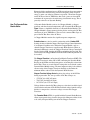
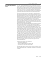
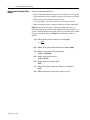
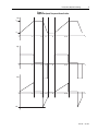
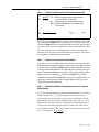
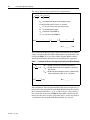
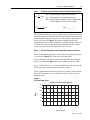
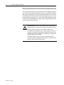
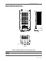
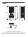
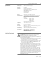
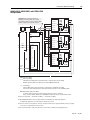
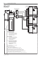
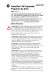
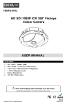
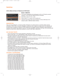
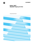
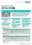
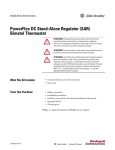
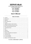
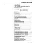
Installation Data
Allen-Bradley
1336/1336VT/1336 PLUS/PLUS II/IMPACT
1336 FORCE Drives
Dynamic Braking
Series D Cat. No. 1336-MOD-KA005, KB005 and KC005
Series D Cat. No. 1336-MOD-KA010, KB010 and KC010
Series D Cat. No. 1336-MOD-KB050 and KC050
Table of Contents
What This Option Provides . . . . . . . . . . . . . . . . . . . . . . . . . . . . . . . . . . . . . . . . . . . . . . . . . . . 2
Where This Option Is Used . . . . . . . . . . . . . . . . . . . . . . . . . . . . . . . . . . . . . . . . . . . . . . . . . . . 2
What These Instructions Contain . . . . . . . . . . . . . . . . . . . . . . . . . . . . . . . . . . . . . . . . . . . . . . 2
How Dynamic Braking Works . . . . . . . . . . . . . . . . . . . . . . . . . . . . . . . . . . . . . . . . . . . . . . . . . 2
How to Select a Dynamic Brake Module . . . . . . . . . . . . . . . . . . . . . . . . . . . . . . . . . . . . . . . . . 5
Table 1a — 200-240V AC Drive Brake Assembly Ratings . . . . . . . . . . . . . . . . . . . . . . . . . . . 16
Table 2a — 380-480V AC Drive Brake Assembly Ratings . . . . . . . . . . . . . . . . . . . . . . . . . . . 16
Table 3a — 500-600V AC Drive Brake Assembly Ratings . . . . . . . . . . . . . . . . . . . . . . . . . . . 16
KA005-KA010, KB005-KB010 and KC005-KC010
Dimensions, Weights and Conduit Entry Locations . . . . . . . . . . . . . . . . . . . . . . . . . . . . . . 17
KB050 and KC050
Dimensions, Weights and Conduit Entry Locations . . . . . . . . . . . . . . . . . . . . . . . . . . . . . . 18
Specifications . . . . . . . . . . . . . . . . . . . . . . . . . . . . . . . . . . . . . . . . . . . . . . . . . . . . . . . . . . . . . 19
Installation Requirements . . . . . . . . . . . . . . . . . . . . . . . . . . . . . . . . . . . . . . . . . . . . . . . . . . . 19
Mounting Requirements . . . . . . . . . . . . . . . . . . . . . . . . . . . . . . . . . . . . . . . . . . . . . . . . . . . . 20
Recommended Brake Configurations . . . . . . . . . . . . . . . . . . . . . . . . . . . . . . . . . . . . . . . . . 21
Brake Fault Contact Monitoring . . . . . . . . . . . . . . . . . . . . . . . . . . . . . . . . . . . . . . . . . . . . . . 22
Brake Fuses . . . . . . . . . . . . . . . . . . . . . . . . . . . . . . . . . . . . . . . . . . . . . . . . . . . . . . . . . . . . . . 22
Brake Module Jumper Settings . . . . . . . . . . . . . . . . . . . . . . . . . . . . . . . . . . . . . . . . . . . . . . . 22
KA005-KA010, KB005-KB010 and KC005-KC010
Terminal Block, Fuse and Jumper Locations . . . . . . . . . . . . . . . . . . . . . . . . . . . . . . . . . . . 23
KB050 and KC050
Terminal Block, Fuse and Jumper Locations . . . . . . . . . . . . . . . . . . . . . . . . . . . . . . . . . . . 24
KA005-KA010, KB005-KB010 and KC005-KC010
Wiring Scheme. . . . . . . . . . . . . . . . . . . . . . . . . . . . . . . . . . . . . . . . . . . . . . . . . . . . . . . . . . . . . 25
KB050 and KC050
Wiring Scheme . . . . . . . . . . . . . . . . . . . . . . . . . . . . . . . . . . . . . . . . . . . . . . . . . . . . . . . . . . . . 26
DC Power Wiring Tables . . . . . . . . . . . . . . . . . . . . . . . . . . . . . . . . . . . . . . . . . . . . . . . . . . . . . 27
Table 1b — DC Brake Power Wiring for 200-240V AC Drives . . . . . . . . . . . . . . . . . . . . . . . . . 27
Table 2b — DC Brake Power Wiring for 380-480V AC Drives . . . . . . . . . . . . . . . . . . . . . . . . . 27
Table 3b — DC Brake Power Wiring for 500-600V AC Drives . . . . . . . . . . . . . . . . . . . . . . . . . 27
1336-5.64 — July, 2005
2
Heavy Duty Dynamic Braking
What This Option Provides
The Heavy Duty Dynamic Braking Option provides a self contained NEMA
Type 1 enclosed assembly that is wired to a 1336 AC Drive. Dynamic
braking can increase the braking torque capability of a drive up to 100%.
Where This Option Is Used
B003-B250 and C003-C250 1336 Drives
B003-B250 1336VT Drives
AQF05-A010, BRF05-B250 and C007-C250 1336 PLUS and 1336 FORCE
Drives
Catalog Number Description
1336 — MOD — K
B
005
1336/1336VT/1336 PLUS/1336 FORCE
Heavy Duty Dynamic Braking
Voltage Rating
A = 230V AC
B = 380/415/460V AC
C = 500/575V AC
Brake Kit Code
005 = Drive Ratings 003-005/F05-F50
010 = Drive Ratings 007-010
050 = Drive Ratings 040-060
What These Instructions
Contain
These instructions describe Dynamic Brake Module operation and explain
how to calculate the data needed to correctly select, configure and install a
Heavy Duty Dynamic Brake Module. By completing How to Select a
Dynamic Brake Module first, you will be able to determine:
1. Whether or not Heavy Duty Dynamic Braking is required for your
application.
2. If Heavy Duty Dynamic Braking is required, the rating and quantity of
brakes required.
How Dynamic Braking Works
When an induction motor’s rotor is turning slower than the synchronous
speed set by the drive’s output power, the motor is transforming electrical
energy obtained from the drive into mechanical energy available at the drive
shaft of the motor. This process is referred to as motoring. When the rotor
is turning faster than the synchronous speed set by the drive’s output power,
the motor is transforming mechanical energy available at the drive shaft of
the motor into electrical energy that can be transferred back into the utility
grid. This process is referred to as regeneration.
Most AC PWM drives convert AC power from the fixed frequency utility
grid into DC power by means of a diode rectifier bridge or controlled SCR
bridge before it is inverted into variable frequency AC power. Diode and
SCR bridges are cost effective, but can only handle power in the motoring
direction. Therefore, if the motor is regenerating, the bridge cannot conduct
the necessary negative DC current, the DC bus voltage will increase and
cause a Bus Overvoltage trip at the drive.
1336-5.64 — July, 2005
Heavy Duty Dynamic Braking
3
Expensive bridge configurations use SCRs or transistors that can transform
DC regenerative electrical energy into fixed frequency utility electrical
energy. A more cost effective solution is to provide a Transistor Chopper
on the DC Bus of the AC PWM drive that feeds a power resistor which
transforms the regenerative electrical energy into thermal energy. This is
generally referred to as Dynamic Braking.
How The Dynamic Brake
Module Works
A Dynamic Brake Module consists of a Chopper Module (a chopper
transistor and related control components) and a Dynamic Brake Resistor.
Figure 1 shows a simplified schematic of a Dynamic Brake Module. The
Chopper Module is shown connected to the positive and negative DC Bus
conductors of an AC PWM Drive. The two series connected Bus Caps are
part of the DC Bus filter of the AC Drive.
A Chopper Module contains five significant power components:
Protective fuses are sized to work in conjunction with a Crowbar SCR.
Sensing circuitry within the Chopper Transistor Voltage Control determines
if an abnormal condition exists within the Chopper Module, such as a
shorted Chopper Transistor or open Dynamic Brake Resistor. When an
abnormal condition is sensed, the Chopper Transistor Voltage Control will
fire the Crowbar SCR, shorting the DC Bus and melting the fuse link. This
action isolates the Chopper Module from the DC Bus until the problem can
be resolved.
The Chopper Transistor is an Insulated Gate Bipolar Transistor (IGBT). The
Chopper Transistor is either ON or OFF, connecting the Dynamic Brake
Resistor to the DC Bus and dissipating power, or isolating the resistor from
the DC Bus. There are several transistor ratings that are used in the various
Dynamic Brake Module ratings. The most important rating is the collector
current rating of the Chopper Transistor that helps to determine the
minimum ohmic value used for the Dynamic Brake Resistor.
Chopper Transistor Voltage Control regulates the voltage of the DC Bus
during regeneration. The average values of DC Bus voltages are:
• 375V DC (for 230V AC input)
• 750 V DC (for 460V AC input)
• 937.5V DC (for 575V AC input)
Voltage dividers reduce the DC Bus voltage to a value that is usable in signal
circuit isolation and control. The DC Bus feedback voltage from the voltage
dividers is compared to a reference voltage to actuate the Chopper
Transistor.
The Freewheel Diode (FWD), in parallel with the Dynamic Brake Resistor,
allows any magnetic energy stored in the parasitic inductance of that circuit
to be safely dissipated during turn off of the Chopper Transistor.
1336-5.64 — July, 2005
4
Heavy Duty Dynamic Braking
Figure 1
Simplified Schematic of Dynamic Brake Module
+ DC Bus
Fuse
Bus Caps
FWD
To
Voltage Dividers
Voltage
Divider
Dynamic
Brake
Resistor
To
Voltage
Control
Signal
Common
Chopper
Transistor
FWD
Chopper Transistor
Voltage Control
Crowbar
SCR
Voltage
Divider
Fuse
To
Crowbar
SCR Gate
To
Voltage
Control
Bus Caps
To
Voltage
Control
– DC Bus
Dynamic Brake Modules are designed to be applied in parallel if the current
rating is insufficient for the application. One Dynamic Brake Module is the
designated Master Dynamic Brake Module, while any other Modules are
the designated Follower Modules.
Two lights are provided on the front of the enclosure to indicate operation.
• DC Power light illuminates when DC power has been applied to the
Dynamic Brake Module.
• Brake On light flickers when the Chopper Module is operating or
chopping.
1336-5.64 — July, 2005
Heavy Duty Dynamic Braking
How to Select a Dynamic Brake
Module
5
As a rule, a Dynamic Brake Module can be specified when regenerative
energy is dissipated on an occasional or periodic basis. In general, the motor
power rating, speed, torque, and details regarding the regenerative mode of
operation will be needed in order to estimate what Dynamic Brake Module
rating to use. When a drive is consistently operating in the regenerative
mode of operation, serious consideration should be given to equipment that
will transform the electrical energy back to the fixed frequency utility.
The peak regenerative power of the drive must be calculated in order to
determine the maximum ohmic value of the Dynamic Brake Resistor of the
Dynamic Brake Module. Once the maximum ohmic value of the Dynamic
Brake Resistor current rating is known, the required rating and number of
Dynamic Brake Modules can be determined. If a Dynamic Brake Resistance
value greater than the minimum imposed by the choice of the peak
regenerative power is made and applied, the drive can trip off due to transient
DC Bus overvoltage problems. Once the approximate ohmic value of the
Dynamic Brake Resistor is determined, the necessary power rating of the
Dynamic Brake Resistor can be calculated.
The wattage rating of the Dynamic Brake Resistor is estimated by applying
what is known about the drive’s motoring and regenerating modes of
operation. The average power dissipation of the regenerative mode must be
estimated and the wattage of the Dynamic Brake Resistor chosen to be
greater than the average regenerative power dissipation of the drive. If the
Dynamic Brake Resistor has a large thermodynamic heat capacity, then the
resistor element will be able to absorb a large amount of energy without the
temperature of the resistor element exceeding the operational temperature
rating. Thermal time constants in the order of 50 seconds and higher satisfy
the criteria of large heat capacities for these applications. If a resistor has
a small heat capacity, defined as thermal time constants less than 5 seconds,
the temperature of the resistor element could exceed maximum temperature
limits during the application of pulse power to the element and could exceed
the safe temperature limits of the resistor. The resistors used in the Dynamic
Brake Modules have thermodynamic time constants of less than 5 seconds.
This means restrictions must be imposed upon the application of the
Dynamic Brake Modules.
Peak regenerative power can be calculated as:
• Horsepower (English units)
• Watts (The International System of Units, SI)
• Per Unit System (pu) which is dimensionless
The final number must be in watts of power to estimate the ohmic value of
the Dynamic Brake Resistor. The following calculations are demonstrated
in SI units.
1336-5.64 — July, 2005
6
Heavy Duty Dynamic Braking
How to Select a Dynamic Brake
Module
Gather the following information:
• Power rating from motor nameplate in watts, kilowatts, or horsepower
• Speed rating from motor nameplate in rpm or rps (radians per second)
• Motor inertia and load inertia in kg-m2 or lb-ft2
• Gear ratio (GR) if a gear is present between the motor and load
• Motor shaft speed, torque, and power profile of the drive application
Figure 2 shows the speed, torque, and power profiles of the drive as a
function of time for a particular cyclic application that is periodic over t4
seconds. The desired time to decelerate is known or calculable and is within
the drive performance limits. In Figure 2, the following variables are
defined:
ω(t) = Motor shaft speed in radians per second (rps)
ω=
2πN
60
N(t)
= Motor shaft speed in Revolutions Per Minute (RPM)
T(t)
= Motor shaft torque in Newton-meters
1.0 lb-ft = 1.355818 N-m
P(t)
= Motor shaft power in watts
1.0 HP = 746 watts
ωb = Rated angular rotational speed
Rad/s
ωo = Angular rotational speed less than ωb (can equal 0)
Rad/s
-Pb
1336-5.64 — July, 2005
= Motor shaft peak regenerative power in watts
Heavy Duty Dynamic Braking
7
Figure 2
Application Speed, Torque and Power Profiles
ω(t)
ωb
ωo
0
t1
t2
t3
t4
t 1 + t4
t
0
t1
t2
t3
t4
t 1 + t4
t
t1
t2
t3
t4
t 1 + t4
t
T(t)
P(t)
0
-Pb
1336-5.64 — July, 2005
8
Heavy Duty Dynamic Braking
Step 1 — Determine the Total Inertia
JT = Jm + (GR2 ✕ JL)
1.0 lb-ft2 = 0.04214011 kg-m2
= Total inertia reflected to the motor shaft (kg-m2)
JT
Jm = Motor inertia (kg-m2)
GR = Gear ratio for any gear between motor and load (dimensionless)
Note: For 2:1 gear ratio, GR = 0.5.
= Load inertia (kg-m2)
JL
JT =
+(
)
✕
JT = __________ kg-m2
Step 2 — Calculate the Peak Braking Power
Pb =
JT ✕ ωb (ωb - ωo)
t3 - t2
JT
= Total inertia reflected to the motor shaft (kg-m2)
ωb = Rated angular rotational speed (Rad / s = 2πNb / 60)
ωo = Angular rotational speed,
Nb
less than rated speed down to zero (Rad / s)
= Rated motor speed (RPM)
t3 - t2 = Deceleration time from ωb to ωo (seconds)
Pb
Pb =
= Peak braking power (watts)
1.0 HP = 746 watts
✕
[
(
–
–
)
]
Pb = __________watts
Compare the peak braking power to that of the rated motor power. If the
peak braking power is greater that 1.5 times that of the motor, then the
deceleration time (t3 - t2) needs to be increased so that the drive does not
go into current limit. (This is assuming that 150% of motor power is less
than or equal to 150% drive capacity.)
1336-5.64 — July, 2005
Heavy Duty Dynamic Braking
9
Step 3 — Calculate the Maximum Dynamic Brake Resistance Value
Rdb1 =
0.9 ✕ Vd2
Vd
Pb
Pb
= DC Bus voltage the chopper module regulates to
(375V DC, 750V DC, or 937.5V DC)
= Peak braking power calculated in Step 2 (watts)
Rdb1 = Maximum allowable value for the dynamic brake
resistor (ohms)
Rdb1 =
[
]
✕
[
Rdb1 = _________ ohms
]
The choice of the Dynamic Brake resistance value should be less than the
value calculated in Step 3. If the resistance value is greater than the value
calculated in Step 3, the drive can trip on DC Bus overvoltage. Do not reduce
Pb by any ratio because of estimated losses in the motor and inverter. This
has been accounted for by an offsetting increase in the manufacturing
tolerance of the resistance value and the increase in resistance value due to
the temperature coefficient of resistor element.
Step 4 — Choose the Correct Dynamic Brake Module
Go to Table 1a, 2a, or 3a in this publication and choose the correct Dynamic
Brake Module based upon the resistance value being less than the maximum
value of resistance calculated in Step 3. If the Dynamic Brake Resistor value
of one Dynamic Brake Module is not sufficiently low, consider using up to
three Dynamic Brake Modules in parallel, such that the parallel Dynamic
Brake resistance is less than Rdb1 calculated in Step 3. If the parallel
combination of Dynamic Brake Modules becomes too complicated for the
application, consider using a Brake Chopper Module with a separately
specified Dynamic Brake Resistor.
Step 5 — Estimate the Minimum Wattage Requirements for the Dynamic
Brake Resistors
It is assumed that the application exhibits a periodic function of acceleration
and deceleration. If (t3 - t2) equals the time in seconds necessary for
deceleration from rated speed to ωo speed, and t4 is the time in seconds
before the process repeats itself, then the average duty cycle is (t3 - t2)/t4.
The power as a function of time is a linearly decreasing function from a
value equal to the peak regenerative power to some lesser value after (t3 t2) seconds have elapsed. The average power regenerated over the interval
of (t3 - t2) seconds is: Pb ωb + ωo
2
(
ωb
)
1336-5.64 — July, 2005
10
Heavy Duty Dynamic Braking
The average power in watts regenerated over the period t4 is:
Pav =
[t3 - t2]
t4
Pb
✕
2
(
ωb + ωo
ωb
)
Pav = Average dynamic brake resister dissipation (watts)
t3 - t2 = Deceleration time from ωb to ωo (seconds)
t4
= Total cycle time or period of process (seconds)
Pb
= Peak braking power (watts)
ωb = Rated motor speed (Rad / s)
ωo = A lower motor speed (Rad / s)
Pav =
[
–
]
[
]
✕
[
]
2
✕
(
+
)
Pav = _________ watts
The Dynamic Brake Resistor power rating of the Dynamic Brake Module
(singly or two in parallel) that will be chosen must be greater than the value
calculated in Step 5. If it is not, then a Brake Chopper Module with the
suitable Dynamic Brake Resistor must be specified for the application.
Step 6 — Calculate the Percent Average Load of the Dynamic Brake Resistor
AL =
AL =
Pav
Pdb
[
[
✕ 100
AL = Average load in percent of Dynamic Brake Resistor
Pav = Average dynamic brake resistor dissipation calculated in
Step 5 (watts)
Pdb = Steady state power dissipation capacity of dynamic brake
resistors obtained from Table 1a, 2a, or 3a (watts)
]
✕ 100
]
AL = _________ %
The calculation of AL is the Dynamic Brake Resistor load expressed as a
percent. Pdb is the sum of the Dynamic Brake Module dissipation capacity
and is obtained from Table 1a, 2a, or 3a. This will give a data point for a
line to be drawn on the curve in Figure 3. The number calculated for AL
must be less than 100%. If AL is greater than 100%, an error was made in
a calculation or the wrong Dynamic Brake Module was selected.
1336-5.64 — July, 2005
Heavy Duty Dynamic Braking
11
Step 7 — Calculate the Percent Peak Load of the Dynamic Brake Resistor
Pb
PL =
Pdb
✕ 100
PL = Peak load in percent of Dynamic Brake Resistor
Pb = Peak braking power calculated in Step 2 (watts)
Pdb = Steady state power dissipation capacity of dynamic brake
resistors obtained from Table 1a, 2a, or 3a (watts)
PL =
[
[
]
✕ 100
]
PL = __________ %
The calculation of PL in percent gives the percentage of the instantaneous
power dissipated by the Dynamic Brake Resistors relative to the steady state
power dissipation capacity of the resistors. This will give a data point to be
drawn on the curve of Figure 3. The number calculated for PL will
commonly fall between 300% and 600%. A calculated number for PL of
less than 100% indicates that the Dynamic Brake Resistor has a higher
steady state power dissipation capacity than is necessary.
Step 8 — Plot the Steady State and Transient Power Curves on Figure 3
Draw a horizontal line equal to the value of AL (Average Load) in percent
as calculated in Step 6. This value must be less than 100%.
Pick a point on the vertical axis equal to the value of PL (Peak Load) in
percent as calculated in Step 7. This value should be greater the 100%.
Draw a vertical line at (t3 - t2) seconds such that the line intersects the AL
line at right angles. Label the intersection point “Point 1”.
Draw a straight line from PL on the vertical axis to Point 1 on the AL line.
This line is the power curve described by the motor as it decelerates to
minimum speed.
Figure 3
Plot Your Power Curve
KA, KB, KC Transient Power Capacity
600
500
Power
(%)
400
300
200
100
0
1
2
3
4
5
6
7
8
9
10
t
(time in seconds)
1336-5.64 — July, 2005
12
Heavy Duty Dynamic Braking
If the line you drew lies to the left of the constant temperature power curve
of the Dynamic Brake Resistor, then there will be no application problem.
If any portion of the line lies to the right of the constant temperature power
curve of the Dynamic Brake Resistor, then there is an application problem.
The application problem is that the Dynamic Brake Resistor is exceeding
its rated temperature during the interval that the transient power curve is to
the right of the resistor power curve capacity. It would be prudent to parallel
another Dynamic Brake Module or apply a Brake Chopper Module with a
separate Dynamic Brake Resistor.
!
1336-5.64 — July, 2005
ATTENTION: The heavy duty dynamic brake unit contains a
thermostat to guard against overheating and component damage.
If the thermostat sensed excessive ambient temperature
associated with a high duty cycle, torque setting, or overload
condition, the thermostat will open and disable the brake until
components cool to rated temperature. During the cooling period,
no brake operation is available.
If reduced braking torque represents a potential hazard to
personnel, auxiliary stopping methods must be considered in the
machine and/or control circuit design.
Heavy Duty Dynamic Braking
Example Calculation
13
A 50 HP, 4 Pole, 460 Volt motor and drive is accelerating and decelerating
as depicted in Figure 2.
• Cycle period (t4) is 60 seconds
• Rated speed is 1785 RPM and is to be decelerated to 0 speed in 6.0
seconds
• Motor load can be considered purely as an inertia, and all power
expended or absorbed by the motor is absorbed by the motor and load
inertia
• Load inertia is directly coupled to the motor
• Motor inertia plus load inertia is given as 9.61 kg-m2
Calculate the necessary values to choose an acceptable Dynamic Brake
Module.
Rated Power = 50 HP × 746 = 37.3 kW
This information was given and must be known before the calculation
process begins. This can be given in HP, but must be converted to watts
before it can be used in the equations.
Rated Speed = 1785 RPM = 2π × 1785/60 = 186.93 Rad/s = ωb
This information was given and must be known before the calculation
process begins. This can be given in RPM, but must be converted to radians
per second before it can be used in the equations.
ωo = 0 RPM = 0 Rad/s
Total Inertia = 9.61 kg-m2 = JT
This value can be in lb-ft2 or Wk2, but must be converted into kg-m2 before
it can be used in the equations.
Deceleration Time = (t3 - t2) = 6.0 seconds.
Period of Cycle = t4 = 60 seconds.
Vd = 750 Volts
This was known because the drive is rated at 460 Volts rms. If the drive
were rated 230 Volts rms, then Vd = 375 Volts, and if the drive were rated
at 575 Volts rms, then Vd = 937.5 Volts.
All of the preceding data and calculations were made from knowledge of
the application under consideration. The total inertia was given and did not
need further calculations as outlined in Step 1.
Peak Braking Power = Pb =
JT × ωb(ωb- ωo)
(t3 - t2)
= 55.95 kW
This is 150% rated power and is equal to the maximum drive limit of 150%
current limit. This calculation is the result of Step 2 and determines the peak
power that must be dissipated by the Dynamic Brake Resistor.
1336-5.64 — July, 2005
14
Heavy Duty Dynamic Braking
Rdb1 = 0.9Vd2/Pb = 9.05 ohms
This calculation is the result of Step 3 and determines the maximum ohmic
value of the Dynamic Brake Resistor. Note that a choice of Vd = 750 Volts
DC was made based on the premise that the drive is rated at 460 Volts.
The most cost-effective combination of Dynamic Brake Modules chosen
in Step 4 is one 1336-MOD-KB050 and one 1336-MOD-KB010 operated
in parallel. This results in an equivalent Dynamic Brake Resistance of
8.76 ohms.
By comparison, a KB050 paralleled with a KB005 results in an equivalent
Dynamic Brake Resistance of 9.57 ohms, which is greater than the
maximum allowable value of 9.05 ohms. If two KB050 Dynamic Brake
Modules are paralleled, the equivalent resistance would be 5.25 ohms,
which will satisfy the resistance criteria set by Step 3, but is not cost
effective.
Pav =
(t3 - t2)
t4
×
Pb
2
(ω ω ω )
b+
o
= 2.8 kW
b
This is the result of calculating the average power dissipation as outlined
in Step 5. Verify that the sum of the power ratings of the Dynamic Brake
Resistors chosen in Step 4 is greater than the value calculated in Step 5.
AL = 100 × Pav/Pdb = 32%
This is the result of the calculation outlined in Step 6 and is less than 100%.
Draw AL as a dotted line on Figure 4.
PL = 100 × Pb/Pdb = 617%
This is the result of the calculation outlined in Step 7 and should always be
greater than 100%.
1336-5.64 — July, 2005
Heavy Duty Dynamic Braking
15
Figure 4
Power Curve Out of Range
KA, KB, KC Transient Power Capacity
PL = 617%
600
500
Power
(%)
400
300
200
100
AL = 32%
0
Point 1
1
2
3
4
5
6
7
8
9
10
t
(time in seconds)
Figure 4 is the result of Step 8. Note that a portion of the motor power curve
lies to the right of the constant temperature power curve of the Dynamic
Brake Resistor. This means that the resistor element temperature is
exceeding the operating temperature limit. This could mean a shorter
Dynamic Brake Resistor life than expected. To alleviate this possibility, use
two KB050 Dynamic Brake Modules in parallel and recalculate.
AL = 20%
PL = 400%
Figure 5
Power Curve In Range
KA, KB, KC Transient Power Capacity
600
500
Power
(%)
PL = 400%
300
200
100
Point 1
AL = 20%
0
1
2
3
4
5
6
7
8
9
10
t
(time in seconds)
Figure 5 is the result of Step 8 using two KB050 Dynamic Brake Modules
in parallel and the graph indicates that the resistive element temperature
will not exceed the operational limit.
1336-5.64 — July, 2005
16
Heavy Duty Dynamic Braking
Table 1a
Maximum Ratings for 230V AC Drives, 375 Volts Turn-on Voltage
Dynamic Brake Module
Catalog No. 1336-MOD-
Resistance Value of Dynamic
Brake Resistor (Ohms)
Average Wattage Dissipation of
Dynamic Brake Resistor (Watts)
KA 005
KA 010
28.0
13.2
666
1650
Table 2a
Maximum Ratings for 380-460V AC Drives, 750 Volts Turn-on Voltage
Dynamic Brake Module
Catalog No. 1336-MOD-
Resistance Value of Dynamic
Brake Resistor (Ohms)
Average Wattage Dissipation of
Dynamic Brake Resistor (Watts)
KB 005
KB 010
KB 050
108.0
52.7
10.5
1500
2063
7000
Table 3a
Maximum Ratings for 575V AC Drives, 937.5 Volts Turn-on Voltage
1336-5.64 — July, 2005
Dynamic Brake Module
Catalog No. 1336-MOD-
Resistance Value of Dynamic
Brake Resistor (Ohms)
Average Wattage Dissipation of
Dynamic Brake Resistor (Watts)
KC 005
KC 010
KC 050
108.0
52.7
15.8
1500
2063
8000
Heavy Duty Dynamic Braking
17
KA005-KA010, KB005-KB010 and KC005-KC010
Dimensions, Weights and Conduit Entry Locations
G
R2
E
B
FOR USE WITH 380/460
DC POWER
BRAKE ON
A–B P\N 151076 REV 01
BULLETIN 1336 DYNAMIC BRAKE
1336–MOD–KB005
SER C
680–750 VDC. 2.5 ADC (RMS)
CAT
INPUT
VAC BULL. 1336 A.F. DRIVES
(OUTPUT) HEAT DISSIPATION
375 WATTS MAXIMUM
MADE IN U.S.A.
R1
F
A
(4 places)
D
F
C
H
(Side)
(Front)
K
Conduit Entry
28.5mm (1.12") Dia. I
I
J
(Bottom)
Dimensions and Weights in Millimeters (Inches) and Kilograms (Pounds)
Option Code
KA005-KA010
KB005-KB010
KC005-KC010
A
B
C
193.5 441.4 174.5
(7.62) (17.38) (6.87)
D
E
F
133.4 425.4 30.0
(5.25) (16.75) (1.18)
G
H
I
6.4
(0.25)
9.7
(0.38)
50.8
(2.00)
J
K
46.0
50.8
(1.81) (16.75)
R1 Dia.
R2 Dia.
Weight
7.1
(0.28)
14.3
(0.56)
6.8
(15.00)
1336-5.64 — July, 2005
18
Heavy Duty Dynamic Braking
KB050 and KC050
Dimensions, Weights and Conduit Entry Locations
G
R2
E2
B
DC POWER
BRAKE ON
INPUT
FOR USE WITH 500/600
A–B P\N 151081 REV 01
BULLETIN 1336 DYNAMIC BRAKE
1336–MOD–KC050
SER B
935 VDC. 10 ADC (RMS)
CAT
VAC BULL. 1336 A.F. DRIVES
(OUTPUT) HEAT DISSIPATION
3750 WATTS MAXIMUM
MADE IN U.S.A.
E1
R1 (6 places)
F
A
(Front)
D
F G
C
(Side)
J
Conduit Entry
28.5mm (1.12") Dia.
H
H
I
(Bottom)
Dimensions and Weights in Millimeters (Inches) and Kilograms (Pounds)
Option Code
KB050
and KC050
A
B
C
D
E1
E2
F
G
H
I
J
K
R1 Dia. R2 Dia. Weight
406.4 609.6 247.7 381.0 304.8 592.3 12.7
17.3
19.1
50.8 152.4 79.3
8.4
14.3
33.8
(16.00) (24.00) (9.75) (15.00) (12.00) (23.32) (0.50) (0.68) (0.75) (2.00) (6.00) (3.12) (0.33) (0.56) (75.00)
1336-5.64 — July, 2005
Heavy Duty Dynamic Braking
Specifications
Braking Torque
100% torque for 20 seconds (typical).
Duty Cycle
20% (typical).
Input Power
DC power supplied from DC Bus.
19
Customer supplied 115V AC, 1∅, 50/60 Hz required for
KB050 & KC050 brake operation.
Enable Signal: 50 mA
Fan Power: 600 mA
Optional
Brake Fault Contact
(1) N.O. contact, TTL compatible, closed when
115V AC is applied, open when a brake fault or loss of power occurs.
Customer supplied 115V AC, 50 mA required for KA005, KB005,
KC005, KA010, KB010 & KC010 optional brake fault contact
monitoring.
UL/CSA Rating:
0.6 Amps, 125VAC.
0.6 Amps, 110VAC.
2.0 Amps, 30VAC.
Initial Contact Resistance: 50mΩ maximum.
Temperature
-10°C to 50°C (14°F to 122°F).
Humidity
5% to 95% non-condensing.
Atmosphere
NEMA Type 1 — Cannot be used in atmospheres having corrosive or
hazardous dust, vapor or gas.
Altitude Derating
1,000 meters (3,300 feet) maximum without derating.
Enclosure Type
KA005, KB005, KC005 — IP20 (NEMA Type 1)
KA010, KB010, KC010 — IP20 (NEMA Type 1)
KB050, KC050 — IP00 (Open)
Installation Requirements
!
ATTENTION: Electric Shock can cause injury or death.
Remove all power before working on this product.
For all Dynamic Brake ratings, DC brake power is supplied from
the drive DC Bus. In addition:
1. Dynamic Brakes KB050 and KC050 have fans and an enable
circuit that requires a 115V AC user power supply.
2. Optional brake fault contact monitoring also requires a 115V
AC user power supply. For KB050 and KC050 brakes, the
same AC power supply may be used.
Hazards of electrical shock exist if accidental contact is made
with parts carrying bus voltage. A bus charged indicator on the
brake enclosures provides visual indication that bus voltage is
present. Before proceeding with any installation or
troubleshooting activity, allow at least one minute after input
power has been removed for the bus circuit to discharge. Bus
voltage should be verified by using a voltmeter to measure the
voltage between the +DC and -DC terminals on the drive power
terminal block. Do not attempt any servicing until bus charged
indicating lights have extinguished and bus voltage has
diminished to zero volts.
1336-5.64 — July, 2005
20
Heavy Duty Dynamic Braking
Mounting Requirements
Dynamic brake enclosures must only be installed in the vertical position.
Select a location using the guidelines below and information provided in
the Recommended Brake Configurations section.
• Each dynamic brake enclosure must be mounted outside of any other
enclosure or cabinet and exposed to unrestricted circulating air for
proper heat dissipation. Allow a minimum of 304.8 mm (12 in.)
between brake enclosures and all other enclosure or cabinets including
the drive.
• Each enclosure must be mounted in an area where the environment
does not exceed the values listed in the specification section of this
publication.
• If only one dynamic brake enclosure is required, the enclosure must be
mounted within 3.0 m (10 ft.) of the drive.
• If more than one KB050 or KC050 brake enclosure is required, a
separate user supplied terminal block must be mounted within 3.0 m
(10 ft.) of the drive. Allow a maximum distance of 1.5 m (5 ft.)
between each brake enclosure and the terminal block.
• If more than one KA005-KA010, KB005-KB010 or KC005-KC010
brake enclosure is required, the first enclosure must be mounted within
3.0 m (10 ft.) of the drive. Allow a maximum distance of 1.5 m (5 ft.)
between each remaining brake enclosure.
• Separate conduit must be provided for the control connections
between multiple brake enclosures.
• Separate conduit must be provided for the DC power connections
between brake enclosures, the terminal block (if required) and the
drive. For AC power connection and conduit requirements, refer to
your 1336, 1336VT, 1336 PLUS II, or 1336 FORCE User Manual.
IMPORTANT: The National Electrical Codes (NEC) and local regulations
govern the installation and wiring of the Heavy Duty Dynamic Brake. DC
power wiring, AC power wiring, control wiring and conduit must be sized
and installed in accordance with these codes and the information supplied
on the following pages.
1336-5.64 — July, 2005
Heavy Duty Dynamic Braking
21
Recommended Brake
Configurations
Brake
Enclosure
304.8 mm
(12 In.)
Minimum
Drive
304.8 mm
(12 In.)
Minimum
3.0 m
(10 ft.)
Maximum
304.8 mm
(12 In.)
Minimum
304.8 mm
(12 In.)
Minimum
Brake
Enclosure
304.8 mm
(12 In.)
Minimum
Drive
1.5 m
(5 ft.)
Maximum
User
Supplied
Terminal
Block
3.0 m
(10 ft.)
Maximum
304.8 mm
(12 In.)
Minimum
304.8 mm
(12 In.)
Minimum
1.5 m
(5 ft.)
Maximum
Brake
Enclosure
Single Brake Enclosure
KA050, KB050 and KC050
Multiple Brake Enclosures
304.8 mm
(12 In.)
Minimum
Drive
304.8 mm
(12 In.)
Minimum
3.0 m
(10 ft.)
Maximum
Brake
Enclosure
304.8 mm
(12 In.)
Minimum
304.8 mm
(12 In.)
Minimum
304.8 mm
(12 In.)
Minimum
1.5 m
(5 ft.)
Maximum
Brake
Enclosure
304.8 mm
(12 In.)
Minimum
1.5 m
(5 ft.)
Maximum
304.8 mm
(12 In.)
Minimum
KA005-KA010, KB005-KB010 and KC005-KC010
Multiple Brake Enclosures
1336-5.64 — July, 2005
22
Heavy Duty Dynamic Braking
Brake Fault Contact Monitoring
For all brake ratings a fault contact has been provided to provide a remote
output signal to an Allen-Bradley 1336-MOD-L3, L6 or PLC. Should a
brake fuse fail, the brake thermostat trip (or for KB050 & KC050 units the
brake enable signal be lost), the brake fault contact will open.
Interconnection wiring for remote brake monitoring is provided in the
Wiring Schemes.
Brake Fuses
All dynamic brakes are internally fused to protect brake components. When
replacing brake fuses, use only the type and size specified below.
Brake Module Jumper Settings
Dynamic Brake
Fuse
Type
Rating
KA005
F1
A50P10 or Equivalent
10A, 500V
KB005
F1
A60Q or Equivalent
5A, 600V
KC005
F1
FWP-5 or Equivalent
5A, 700V
KA010
F1
A50P20 or Equivalent
20A, 500V
KB010
F1
A60Q or Equivalent
10A, 600V
KC010
F1
FWP-10 or Equivalent
10A, 700V
KB050
F1 & F2
A70QS35 or Equivalent
35A, 700V
KC050
F1 & F2
A70QS35 or Equivalent
35A, 700V
For the Recommended Brake Configurations shown on the previous page as
well as the interconnection diagrams shown on the following pages, there
can be only one master brake to control dynamic braking. When multiple
brakes are used, only one brake can serve as the master brake to control the
remaining slave brakes.
KA005-KA010
KB005-KB010
KC005-KC010
KB050
KC050
W1 S
1
2
3
M
Slave/Master
Jumper
Set to
Master
KA005-KA010
KB005-KB010
KC005-KC010
M
3
2
1
S
Master Brake Module Jumper Settings
For the master brake, leave slave/master
jumper W1 factory set to master — Between
jumper positions 2 & 3.
W1
KB050
KC050
Slave Brake Module Jumper Settings
In each slave enclosure, reset jumper W1 to
slave — Between jumper positions 1 & 2
W1 S
1
2
3
M
Slave/Master
Jumper
Set to
Slave
KB005-KB010
M
3
2
1
S
W1
KB050
W2
460V
1
2
3
380V
1336-5.64 — July, 2005
Input
Voltage
Jumper
Set to
460V
3
2
1
W2
380V
V SELECT
460V
Input Voltage Jumper Settings
For KB brakes, remember to set jumper W2
in all enclosures to correspond to the
nominal drive input voltage. Setting the
jumper between positions 1 & 2 will select
an input voltage of 415/460 volts. Setting the
jumper between positions 2 & 3 will select
an input voltage of 380 volts.
KA and KC brakes do not have input voltage
jumpers.
Heavy Duty Dynamic Braking
23
KA005-KA010, KB005-KB010 and KC005-KC010
Terminal Block, Fuse and Jumper Locations
Side View
Front View
W1 S
Slave/Master Jumper W1
1
2
3
M
Input Voltage Select Jumper W2
KB005-KB010 Units Only
W2
460V
1
2
3
380V
Brake
Module
Board
Relay
Option
Board
Fuse F1
KA005-KA010
and
KC005-KC010 Units Only
W1 S
1
2
3
W2
460V
1
2
3
M 380V
DS1
1 2 3 4
DS1
DC Power ON Light
DS2
TB3
1
2
3
4
5
6
SLAVE IN. MASTER OUT DC BUS FUSE
(+)
(–) (–)
(+)
(–) (+)
F1
TERMINAL STRIP TB–1
DS2
Brake ON Light
Brake Fault Contact
Terminal Block TB3
Power and Control
Terminal Block TB1
Brake Chassis
Ground Screw
Fuse F1
KB005-KB010 Units Only
1336-5.64 — July, 2005
24
Heavy Duty Dynamic Braking
KB050 and KC050
Terminal Block, Fuse and Jumper Locations
Brake Module Board
DC Power ON Light
DS1
Brake Fault Contact
Terminal Block TB3
TB3
2
Brake ON Light
DS2
1
DS1
DS2
TB3
M
380V
V. SEL
460V
3
2
1
S
W1
W2
Fuse F1
Input Voltage Select
Jumper W2
KB050 Units Only
380V
V SELECT
460V
3
2
1
W2
1
2
3
4
5
6
7
8 9 10
Slave/Master
Jumper W1
M
Power and Control
Terminal Block TB1
SLAVE IN.MASTER OUT DC BUS 120VAC
(+) (–) (–) (+) (–) (+) POWER
TERMINAL STRIP TB–1
120VAC
ENABLE
3
2
1
S
W1
Fuse F2
Brake Chassis Ground Screw
1336-5.64 — July, 2005
Heavy Duty Dynamic Braking
25
KA005-KA010, KB005-KB010 and KC005-KC010
Wiring Scheme
Important: Series A 1336 PLUS (A4 frames)
380-480V, 5.5-7.5 kW/7,5-10 HP, do not use the
-DC terminal for brake connection. A separate -BRK
terminal is supplied for proper brake connection.
L1
115V AC
L2
L3 +DC -DC
1
(+) SLAVE IN.
2
(–) SLAVE IN.
TB1
TB3 1
2
3
(–) MASTER OUT
4
(+) MASTER OUT
5
(–) DC BUS
6
(+) DC BUS
➋
➌
3
4
Master
Brake
➍
-BRK
TB1
Drive
MOD-L3 or L6
START
19
STOP
START
20
STOP
21
COM
TB3
1
(+) SLAVE IN.
2
(–) SLAVE IN.
TB1
TB3 1
2
3
(–) MASTER OUT
4
(+) MASTER OUT
5
(–) DC BUS
6
(+) DC BUS
➋
➌
3
4
Slave
Brake
➍
22
23
1
24
➊
CUSTOMER
ENABLE
(+) SLAVE IN.
TB1
TB3 1
2
(–) SLAVE IN.
2
3
(–) MASTER OUT
3
26
4
(+) MASTER OUT
27
5
(–) DC BUS
28
6
(+) DC BUS
25
COM
29
COM
30
ENABLE
➋
➌
4
Slave
Brake
➍
Brake Power Wiring
Brake Power Wiring
All DC Brake Power Wiring must be twisted pair and run in conduit separate from Control Wiring.
Minimum required DC Brake Power Wiring sizes are listed in tables 1b, 2b and 3b.
Control Wiring
All Control Wiring must be twisted pair and run in conduit separate from DC Brake Power Wiring.
Interconnection Control Wiring between the brake terminals must be twisted pair, 1 mm2 (18 AWG) minimum.
Optional Brake Fault Contact Wiring
A separate 115V AC power supply is required if the brake fault contacts are to be monitored.
Refer to your 1336, 1336VT, 1336 PLUS, or 1336 FORCE User Manual for wire selection and installation details.
➊ Connect to AUX at TB3 — Terminal 24 for L6 Option — Terminal 28 for L3 Option.
➋ The MASTER OUT terminals are factory jumpered and must remain jumpered for single brake applications.
For multiple brake applications, remove the jumpers in all but the last enclosure.
➌ Contact is shown in a de-energized state. Contact is closed when 115V AC power is applied to TB3 and pilot relay is energized.
Loss of power or a brake malfunction will open contact.
➍ Connect the brake frame to earth ground. Refer to the connected drive's User Manual for grounding instructions.
1336-5.64 — July, 2005
26
Heavy Duty Dynamic Braking
KB050 and KC050
Wiring Scheme
115V AC ➌
(user supplied)
Auxiliary Term Block ➋
(user supplied)
-DC
-DC
L1
115V AC
L2
L3 +DC -DC
-DC
TB1
1
(+) SLAVE IN.
2
(–) SLAVE IN.
TB1
+DC
+DC
MOD-L3 or L6
START
STOP
19
START
20
STOP
21
COM
TB3
5
(–) DC BUS
6
7
(+) DC BUS
8
9
120VAC POWER
10
120VAC ENABLE
120VAC ENABLE
Master Brake
➏
1
(+) SLAVE IN.
2
(–) SLAVE IN.
(–) DC BUS
(+) DC BUS
120VAC POWER
22
8
9
23
10
120VAC ENABLE
2
120VAC POWER
120VAC ENABLE
Slave Brake
➏
COM
27
1
(+) SLAVE IN.
2
(–) SLAVE IN.
TB1
TB3
➎
1
2
3 (–) MASTER OUT
➍
4 (+) MASTER OUT
28
29
COM
30
ENABLE
+DC Brake Power Wiring
-DC Brake Power Wiring
All DC Brake Power Wiring must be twisted pair
and run in conduit separate from Control Wiring.
Minimum required DC Brake Power Wiring sizes
are listed in tables 1b, 2b and 3b.
Control Wiring
All Control Wiring must be twisted pair and run
in conduit separate from DC Brake Power Wiring.
Interconnection Control Wiring between the
brake terminals must be twisted pair,
1 mm2 (18 AWG) minimum.
Optional Brake Fault Contact Wiring
A separate 115V AC power supply is required if
the brake fault contacts are to be monitored.
Refer to your 1336, 1336VT, 1336 PLUS, or
1336 FORCE User Manual for wire selection
and installation details.
➊ Connect to AUX at TB3 — Terminal 24 for L6 Option
— Terminal 28 for L3 Option.
➋ When more than KB050 or KC050 brake
is required, a separate user supplied Auxiliary Term
Block is also required — A-B Catalog Number 1492-PDM3141 or equivalent.
➌ A separate 115V AC power supply is required to operate fans and enable the brake.
➍ The MASTER OUT terminals are factory jumpered and must remain jumpered for single brake
applications. For multiple brake applications, remove the jumpers in all but the last enclosure.
➎ Contact is shown in a de-energized state. Contact is closed when 115V AC power is applied to TB3 and
pilot relay is energized. Loss of power or a brake malfunction will open contact.
➏ Connect the brake frame to earth ground. Refer to the connected drive's User Manual for grounding instructions.
1336-5.64 — July, 2005
1
3 (–) MASTER OUT
➍
4 (+) MASTER OUT
6
7
26
CUSTOMER
ENABLE
TB3
➎
TB1
24
➊
2
120VAC POWER
5
25
1
3 (–) MASTER OUT
➍
4 (+) MASTER OUT
+DC
Drive
TB3
➎
5
(–) DC BUS
6
7
(+) DC BUS
8
9
120VAC POWER
10
120VAC ENABLE
120VAC POWER
120VAC ENABLE
Master Brake
➏
Heavy Duty Dynamic Braking
DC Power Wiring Tables
27
Required Minimum DC Power Wiring Sizes in mm2 and (AWG)
Table 1b — DC Brake Power Wiring for 200-240V AC Drives
for drive rating
AQF05-AQF50
with
(1) KA005
A007-A010
(1) KA010
Drive – Master
or
Drive – Auxiliary Term Block Auxiliary Term Block - Master Master – Slave
wire size
wire size
wire size
—
6 (10)
—
—
6 (10)
—
Slave – Slave
wire size
—
—
A015
(1) KA005 + (1) KA010
—
6 (10)
6 (10)
—
A020
(2) KA010
—
6 (10)
6 (10)
—
Table 2b — DC Brake Power Wiring for 380-480V AC Drives
for drive rating
BRF05-BRF50
B003-B005
B007-B010
B015
B020
BX040
BX060
B040-B060
B075-B100
with
Drive – Master
or
Drive – Auxiliary Term Block Auxiliary Term Block - Master Master – Slave
wire size
wire size
wire size
Slave – Slave
wire size
(1) KB005
—
4 (12)
—
—
(1) KB010
—
4 (12)
—
—
(1) KB005 + (1) KB010
—
4 (12)
4 (12)
—
(2) KB010
—
4 (12)
4 (12)
—
(1) KB050
—
6 (10)
—
—
(2) KB050
16 (6)
6 (10)
—
—
Table 3b — DC Brake Power Wiring for 500-600V AC Drives
Drive – Master
or
Drive – Auxiliary Term Block Auxiliary Term Block - Master Master – Slave
wire size
wire size
wire size
—
4 (12)
—
Slave – Slave
wire size
—
for drive rating
C003-C005
with
(1) KC005
C007-C010
(1) KC010
—
4 (12)
—
—
C015
(1) KC005 + (1) KC010
—
4 (12)
4 (12)
—
C020
(2) KC010
—
4 (12)
4 (12)
—
C040-C060
(1) KC050
—
6 (10)
—
—
C075-C100
(2) KC050
16 (6)
6 (10)
—
—
1336-5.64 — July, 2005
www.rockwellautomation.com
Power, Control and Information Solutions Headquarters
Americas: Rockwell Automation, 1201 South Second Street, Milwaukee, WI 53204-2496 USA, Tel: (1) 414.382.2000, Fax: (1) 414.382.4444
Europe/Middle East/Africa: Rockwell Automation, Pegasus Park, De Kleetlaan 12a, 1831 Diegem, Belgium, Tel: (32) 2 663 0600, Fax: (32) 2 663 0640
Asia Pacific: Rockwell Automation, Level 14, Core F, Cyberport 3, 100 Cyberport Road, Hong Kong, Tel: (852) 2887 4788, Fax: (852) 2508 1846
Publication 1336-5.64 — July, 2005
Supersedes May, 2005
P/N 156079
Copyright © 2005 Rockwell Automation, Inc. All rights reserved.
Printed in USA