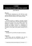
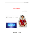
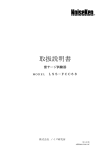
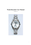
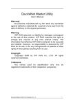
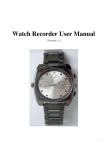
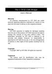
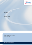
1
I-2534 & I-5534-M Industrial 4-port CAN bus switch User Manual Warranty All products manufactured by ICP DAS are under warranty regarding defective materials for a period of one year from the date of delivery to the original purchaser. Warning ICP DAS assumes no liability for damages resulting from the use of this product. ICP DAS reserves the right to change this manual at any time without notice. The information furnished by ICP DAS is believed to be accurate and reliable. However, no responsibility is assumed by ICP DAS for its use, or for any infringements of patents or other rights of third parties resulting from its use. Copyright Copyright 2012 by ICP DAS. All rights are reserved. Trademark The names used for identification only may be registered trademarks of their respective companies. I-2534 & I-5534-M Industrial 4-port CAN bus switch User Manual (v1.0, 2012/07) ---- 1 Revision Version Firmware Version Date Author 1.1 1.0 Description 1.0 2012 09/14 Johney Update errata. 1.0 2012 05/25 Johney New release. I-2534 & I-5534-M Industrial 4-port CAN bus switch User Manual (v1.0, 2012/07) ---- 2 Tables of Content Revision..........................................................................................................2 1 Introduction.............................................................................................5 1.1 Specifications ................................................................................8 1.2 I-2534 & I-5534-M Features............................................................9 1.3 Product Check List ......................................................................10 2 Technical data ....................................................................................... 11 2.1 Block Diagram.............................................................................. 11 2.2 CAN bus Pin Assignment of the I-2534 ......................................12 2.3 CAN bus Pin Assignment of the I-5534-M..................................13 2.4 Power & RS-232 Pin Assignment of the I-2534..........................14 2.5 Power & RS-232 Pin Assignment of the I-5534-M .....................15 2.6 LED Indicator of the I-2534..........................................................16 2.7 LED Indicator of the I-5534-M .....................................................17 2.8 Terminal Resistors to the I-2534 .................................................18 2.9 Terminal Resistor to the I-5534-M...............................................19 2.10 Rotary Switch & CAN Baud Rate of the I-2534 ..........................21 2.11 Rotary Switch & CAN Baud Rate of the I-5534-M ......................22 2.12 Normal / Initial Mode Switch of the I-2534 .................................23 2.13 Normal / Initial Mode Switch of the I-5534-M .............................24 2.14 CAN bus Wire Connection of the I-2534 ....................................25 2.15 CAN bus Wire Connection of the I-5534-M ................................26 3 Network Deployment ............................................................................27 3.1 Driving Capability ........................................................................27 3.2 Star / Tree Topology.....................................................................28 3.3 I2534_I5534M Utility Tool & RS-232 Cable .................................29 3.4 Route Path Configuration ...........................................................31 3.5 CAN User-defined Baud Rate Configuration .............................35 3.6 CAN Filter Configuration.............................................................36 3.6.1 Apply a New CAN Filter to I-2534 or I-5534-M ...............37 3.6.2 Set the I-2534 or I-5534-M by Configuration File...........42 3.6.3 Read I-2534 or I-5534-M CAN Filter Configuration........43 4 Propagation Delay of the I-2534 and I-5534-M....................................44 5 Dimension of the I-2534........................................................................46 6 Dimension of the I-5534-M ...................................................................47 7 Appendix A : Frequency Ask Questions .............................................51 7.1 How to share the loading of the CAN bus? ...............................51 I-2534 & I-5534-M Industrial 4-port CAN bus switch User Manual (v1.0, 2012/07) ---- 3 7.2 How to listen the single direction CAN messages?..................53 7.3 How to reduce the devices loading?..........................................55 I-2534 & I-5534-M Industrial 4-port CAN bus switch User Manual (v1.0, 2012/07) ---- 4 1 Introduction The I-2534 and I-5534-M are both CAN switch used to establish a connection among four CAN bus sub-networks. In order to solve the problem of the star topology within the CAN network, the I-2534 and I-5534-M are specially designed for integrating four CAN networks or solving the star topology. Not just like general CAN repeater, the I-2534 and I-5534-M have three more important features. (1) Extends the CAN bus working distance. (2) Connects four CAN sub-networks with the different baud rate. (3) Enhances the capacity of CAN network. The limitation of the CAN bus transmission distance on each CAN port is independent, which means the total CAN network distance can be extended by the routing mechanism as the figure 1-1. Figure 1-1: Application to extern the transmission distance I-2534 & I-5534-M Industrial 4-port CAN bus switch User Manual (v1.0, 2012/07) ---- 5 The I-2534 and I-5534-M could transfer the CAN messages among four independent CAN networks. When the CAN bus system on one port of the I-2534 or I-5534-M has some errors (e.g. short circuit), it will not affect the system on the other three ports. Besides, the I-2534 and I-5534-M both provide the message filters; this feature is useful while there are different bus loadings and baud rates on these CAN ports. The baud rate of four CAN ports can be different for highly flexibility as shown in the figure 1-2. Figure1-2: Application to integrate the devices with the different baud rates. I-2534 & I-5534-M Industrial 4-port CAN bus switch User Manual (v1.0, 2012/07) ---- 6 The I-2534 and I-5534-M could combine the different CAN sub-networks, so it enhances the maximum capacity in the single CAN network. The application likes figure 1-3. Figure1-3: Application to enhance the capacity of the CAN network. I-2534 & I-5534-M Industrial 4-port CAN bus switch User Manual (v1.0, 2012/07) ---- 7 1.1 Specifications Module Name CAN Interface Transceiver Channel number Specification Baud Rate (bps) Baud Rate Selection Isolation Terminator Resistor I-2534 I-5534-M NXP TJA1042 4 ISO-11898-2, CAN 2.0A and CAN 2.0B 5k, 10 k, 20 k, 33.3 k, 50 k, 62.5 k, 83.3 k, 125 k, 250 k, 500 k, 800 k, 1 M bps and user-defined Selectable by rotary switch 3000 VDC for DC-to-DC, 2500 Vrms for photo-couple Selectable 120Ω terminator Selectable 120Ω terminator resistor by DIP switch resistor by internal jump 3-pin screwed terminal with 9-pin male D-Sub with CAN Connector CAN_L, CAN_H, CAN_GND CAN_GND, CAN_SHLD, CAN_H, CAN_L CAN Filter Configurable by user RS-232 Configuration Interface RS-232 3-pin screwed terminal block 9-pin female D-Sub with Connector (TxD, RxD, GND ) (TxD, RxD, GND ) Power Input range Unregulated +10 ~ +30 VDC Consumption 3W 1.5W Mechanism Installation DIN-Rail Wall-Mounting Casing Flame-Resistant plastic case aluminum metallic case Dimensions 32.3 x 99 x 77.5 mm 116.5 x 127 x 61.3 mm (W x L x H) Environment Operating Temp. -25 ~ 75 ℃ -30 ~ 80 ℃ Storage Temp. Humidity 10 ~ 90% RH, non-condensing ESD protection 4 kV Contact for each channel EFT protection 500V for signal, 1000V for power EMI certification 30M ~ 1G pass Hi-pot protection 1kV pass Surge protection 1kV pass I-2534 & I-5534-M Industrial 4-port CAN bus switch User Manual (v1.0, 2012/07) ---- 8 1.2 I-2534 & I-5534-M Features 4 CAN communication ports with screw terminal connector for I-2534 or with 9-Pin D-Sub connector for I-5534-M. Flame-Resistant plastic case (I-2534) or aluminum metallic case (I-5534-M). TJA1042 CAN transceiver. Compatible with CAN specification 2.0A and 2.0B. Fully compatible with the ISO 11898-2 standard. Baud rate : 5 k, 10 k, 20 k, 33.3 k, 50 k, 62.5 k, 83.3 k, 125 k, 250 k, 500 k, 800 k, 1 M bps and user-defined. Configurable CAN message filter. Configurable CAN message route path. 100-frame buffer for each CAN channel. Max data flow up to 2500 fps for total CAN channels. Selectable baud rate by the rotary switch. 120Ω terminator resistors selected by the DIP switch (I-2534) or by the jumper (I-5534-M). LED indication for the CAN status. Utility tool for the CAN filter, route path and user-defined baud rate configuration. 2500 Vrms isolation on the CAN side 3 kV galvanic isolation between the power supply and CAN channel 4 kV ESD protection for each CAN channel I-2534 & I-5534-M Industrial 4-port CAN bus switch User Manual (v1.0, 2012/07) ---- 9 1.3 Product Check List The package of the I-2534 includes the following items: I-2534 module; Software CD ROM; Quick Start manual; Release Note ----------------------------------------------------------------------------------------------------- The package of the I-5534-M includes the following items: I-5534-M module; Software CD ROM; Quick Start manual; Release Note It is recommended that users should read the quick start manual first. All of the important information needed will be provided in the quick start as follows: Where you can find the software driver, utility and demo programs. How to install software & utility. Where is the diagnostic program? FAQs and answers. Attention ! If any of these items are missing or damaged, please contact your local field agent. Keep aside the shipping materials and carton in case you want to ship or store the product in the future. I-2534 & I-5534-M Industrial 4-port CAN bus switch User Manual (v1.0, 2012/07) ---- 10 2 Technical data 2.1 Block Diagram The figure 2-1 is the block diagram illustrating the functions of the I-2534 and I-5534-M module. Figure 2-1 Block Diagram of the I-2534 & I-5534-M I-2534 & I-5534-M Industrial 4-port CAN bus switch User Manual (v1.0, 2012/07) ---- 11 2.2 CAN bus Pin Assignment of the I-2534 The figure 2-2 illustrates the CAN bus pins. Figure 2-2 CAN bus pins of the I-2534 Name Port CH1 CL1 Description CAN_High, signal line of CAN port. 1 CAN_Low, signal line of CAN port. CG1 CAN_Ground, ground voltage level of CAN port. CH2 CAN_High, signal line of CAN port. CL2 2 CAN_Low, signal line of CAN port. CG2 CAN_Ground, ground voltage level of CAN port. CH3 CAN_High, signal line of CAN port. CL3 3 CAN_Low, signal line of CAN port. CG3 CAN_Ground, ground voltage level of CAN port. CH4 CAN_High, signal line of CAN port. CL4 CG4 4 CAN_Low, signal line of CAN port. CAN_Ground, ground voltage level of CAN port. I-2534 & I-5534-M Industrial 4-port CAN bus switch User Manual (v1.0, 2012/07) ---- 12 2.3 CAN bus Pin Assignment of the I-5534-M The figure 2-3 illustrates the CAN bus pins. Figure 2-3 Port CAN1 CAN2 CAN3 CAN4 Pin CAN bus pins of the I-5534-M Description 2 CAN_Low, signal line of CAN port. 3 CAN_Ground, ground voltage level of CAN port. 5 CAN_Shield which connected to the F.G. 7 CAN_High, signal line of CAN port. 2 CAN_Low, signal line of CAN port. 3 CAN_Ground, ground voltage level of CAN port. 5 CAN_Shield which connected to the F.G. 7 CAN_High, signal line of CAN port. 2 CAN_Low, signal line of CAN port. 3 CAN_Ground, ground voltage level of CAN port. 5 CAN_Shield which connected to the F.G. 7 CAN_High, signal line of CAN port. 2 CAN_Low, signal line of CAN port. 3 CAN_Ground, ground voltage level of CAN port. 5 CAN_Shield which connected to the F.G. 7 CAN_High, signal line of CAN port. I-2534 & I-5534-M Industrial 4-port CAN bus switch User Manual (v1.0, 2012/07) ---- 13 2.4 Power & RS-232 Pin Assignment of the I-2534 The figure 2-4 shows the pin assignment of the power and the RS-232 port. Take a note that the GND pin of the RS-232 port and CAN 4 share one GND pin. Figure 2-4 RS-232 and Power pin assignment of the I-2534 Name Description TxD TXD pin of RS-232 port. RxD RXD pin of RS-232 port. CG4(GND) SG (or GND) pin of RS-232 port. CAN4 GND and RS-232 GND use the same pin “CG4”. Name PWR Description Voltage Source Input. +10VDC ~ +30VDC. GND Power Ground. I-2534 & I-5534-M Industrial 4-port CAN bus switch User Manual (v1.0, 2012/07) ---- 14 2.5 Power & RS-232 Pin Assignment of the I-5534-M The figure 2-5 shows the pin assignment of the power and the RS-232 port. Figure 2-5 RS-232 and Power pin assignment of the I-5534-M Name Description TxD RS-232 TXD pin of the I-5534-M. Connect to PC’s RxD pin. RxD RS-232 RXD pin of the I-5534-M. Connect to PC’s TxD pin. GND RS-232 GND pin of the I-5534-M. Connect to PC’s GND pin. Name Description PWR Voltage Source Input. +10VDC ~ +30VDC. GND Power Ground. F.G Frame Ground. I-2534 & I-5534-M Industrial 4-port CAN bus switch User Manual (v1.0, 2012/07) ---- 15 2.6 LED Indicator of the I-2534 The figure 2-6 shows the names and statuses of the LEDs. Figure 2-6 CAN LED and Power LED of the I-2534 LED Name LED Color PWR LED OFF The I-2534 has no power. RED The I-2534 has power. LED Name LED Color CAN Status Description CAN1 CAN2 CAN3 CAN4 OFF The CAN port doesn’t transmit or receive message now. Description GREEN The CAN port is transmitting or receiving message now. RED The CAN port have some errors when transmitting message. Note: In the initial mode, the CAN1 ~ CAN4 LEDs will be all twinkled once per second. I-2534 & I-5534-M Industrial 4-port CAN bus switch User Manual (v1.0, 2012/07) ---- 16 2.7 LED Indicator of the I-5534-M The figure 2-7 shows the LED name and its status. Figure 2-7 CAN LED and Power LED of the I-5534-M LED Name LED Color PWR LED OFF The I-5534-M has no power source. RED The I-5534-M has power. LED Name LED Color CAN Status Description CAN1 CAN2 CAN3 CAN4 OFF The CAN port doesn’t transmit or receive message now. Description GREEN The CAN port is transmitting or receiving message now. RED The CAN port have some errors when transmitting message. Note: In the initial mode, the CAN1 ~ CAN4 LEDs will be all twinkled once per second. I-2534 & I-5534-M Industrial 4-port CAN bus switch User Manual (v1.0, 2012/07) ---- 17 2.8 Terminal Resistors to the I-2534 Each CAN port of the I-2534 includes one built-in 120Ω terminal resistor, users can decide whether it is enable or not. The DIP switch for terminal resistor is shown in the figure 2-8. Figure 2-8 120Ω terminal resistors of the I-2534 DIP No. Switch status CAN bus resistor status ON CAN 1 with 120Ω terminal resistor. OFF CAN 1 without terminal resister. ON CAN 2 with 120Ω terminal resister. OFF CAN 2 without terminal resister. ON CAN 3 with 120Ω terminal resister. OFF CAN 3 without terminal resister. ON CAN 4 with 120Ω terminal resister. OFF CAN 4 without terminal resister. 5 N/A Not Available 6 N/A Not Available 1 2 3 4 I-2534 & I-5534-M Industrial 4-port CAN bus switch User Manual (v1.0, 2012/07) ---- 18 2.9 Terminal Resistor to the I-5534-M Each CAN port of the I-5534-M includes one built-in 120Ω terminal resistor, users can decide whether it is enable or not. After removing the upper cover, the jumpers of the terminal resistors are shown in the figure 2-9 and figure 2-10. Figure 2-9 120Ω terminal resistors of the I-5534-M Jump No. CAN bus120Ω resistor JP3 CAN 1 terminal resistor. JP4 CAN 2 terminal resistor. JP5 CAN 3 terminal resistor. JP6 CAN 4 terminal resistor. Figure 2-10 Enable / Disable 120Ω terminal resistors of the I-5534-M I-2534 & I-5534-M Industrial 4-port CAN bus switch User Manual (v1.0, 2012/07) ---- 19 In order to reduce the reflection effects on the CAN bus line, the CAN bus line has to be terminated at both ends by two terminator resistors. According to the ISO 11898-2 spec, each terminator resistor is 120Ω (or between 108Ω~132Ω). The bus topology and the positions of these terminator resistors are shown as the figure 2-11. Figure 2-11 120Ω terminal resistor position Generally, if your application is as the figure 2-12, we recommend you to enable the terminator resistor. Figure 2-12 Enable the 120Ω terminal resistors of the I-2534 / I-5534-M If your application is like the structure as the figure 2-13, the terminator resistor is not needed. Figure 2-13 Disable the 120Ω terminal resistors of the I-2534 / I-5534-M I-2534 & I-5534-M Industrial 4-port CAN bus switch User Manual (v1.0, 2012/07) ---- 20 2.10 Rotary Switch & CAN Baud Rate of the I-2534 The figure 2-14 illustrates where to set the CAN bus baud rate of four CAN ports in the I-2534 module. Figure 2-14 CAN baud rate configuration Switch Value CAN bus Baud Rate 0 5 kbps 1 10 kbps 2 20 kbps 3 33.3 kbps 4 50 kbps 5 62.5 kbps 6 83.3 kbps 7 100 kbps 8 125 kbps 9 250 kbps A 500 kbps B 800 kbps C 1 Mbps D User-defined baud rate. E~F Not available I-2534 & I-5534-M Industrial 4-port CAN bus switch User Manual (v1.0, 2012/07) ---- 21 2.11 Rotary Switch & CAN Baud Rate of the I-5534-M The figure 2-15 illustrates where to set the CAN bus baud rate of four CAN ports in the I-5534-M module. Figure 2-15 CAN baud rate configuration Switch Value CAN bus Baud Rate 0 5 kbps 1 10 kbps 2 20 kbps 3 33.3 kbps 4 50 kbps 5 62.5 kbps 6 83.3 kbps 7 100 kbps 8 125 kbps 9 250 kbps A 500 kbps B 800 kbps C 1 Mbps D User-defined baud rate. E~F Not available I-2534 & I-5534-M Industrial 4-port CAN bus switch User Manual (v1.0, 2012/07) ---- 22 2.12 Normal / Initial Mode Switch of the I-2534 The figure 2-16 illustrates the mode of the I-2534 module. In general usage, users should take care about the position of this switch. Figure 2-16 Mode Name Normal Initial Operation Mode of the I-2534 module The I-2534 Status Description The I-2534 is in the normal mode. The I-2534 is in the configurable status. Users could use the “I2534_Utility” to configure the route path, CAN filter or user-defined CAN baud rate. In the initial mode, the CAN1 LED ~ CAN4 LED will be all twinkled once per second. I-2534 & I-5534-M Industrial 4-port CAN bus switch User Manual (v1.0, 2012/07) ---- 23 2.13 Normal / Initial Mode Switch of the I-5534-M The figure 2-17 illustrates the mode of the I-5534-M module. In general usage, users should take care about the position of this switch. Figure 2-17 Mode Name Normal Initial Operation Mode of the I-5534-M module The I-5534-M Status Description The I-5534-M is in the normal mode. The I-2534 is in the configurable status. Users could use the “I2534_Utility” to configure the route path, CAN filter or user-defined CAN baud rate. In the initial mode, the CAN1 LED ~ CAN4 LED will be all twinkled once per second. I-2534 & I-5534-M Industrial 4-port CAN bus switch User Manual (v1.0, 2012/07) ---- 24 2.14 CAN bus Wire Connection of the I-2534 The CAN bus wire connection of the I-2534 is displayed in the figure 2-18. Figure 2-18 CAN bus wire connection with the I-2534 module The I-2534 has a metallic board attached to the back of the plastic frame. When users mount the I-2534 onto a metal DIN-Rail, users can connect the DIN-Rail to Earth Ground. The figure 2-19 shows the detail. Figure 2-19 Metallic Board at Back of the I-2534 I-2534 & I-5534-M Industrial 4-port CAN bus switch User Manual (v1.0, 2012/07) ---- 25 2.15 CAN bus Wire Connection of the I-5534-M The CAN bus wire connection of the I-5534-M is displayed in the figure 2-20. Figure 2-20 CAN bus wire connection with the I-5534-M module I-2534 & I-5534-M Industrial 4-port CAN bus switch User Manual (v1.0, 2012/07) ---- 26 3 Network Deployment 3.1 Driving Capability Before introducing the driving capability of the I-2534 or I-5534-M, some characteristics of copper cable must be assumed. The AC parameters are 120Ω impedance and 5 ns/m line delay, and the DC parameter follows the table shown below. Table 3-1 Recommended DC parameters for CAN Bus Line Wire Cross-Section [mm2] Resistance [Ω/km] ~0.25 (AWG23) < 90 ~0.5 (AWG20) < 50 ~0.8 (AWG18) < 33 ~1.3 (AWG16) < 20 Under the conditions described above, users can refer to the following table to know the maximum node numbers in each segment and the maximum segment length when using different type of wire. Table 3-2 Wire CrossSection [mm2] Driving Capability The maximum segment length [m] under the case of specific node number in this segment 16 Nodes 32 Nodes 64 Nodes 100 Nodes ~0.25 (AWG23) < 220 < 200 < 170 < 150 ~0.5 (AWG20) < 390 < 360 < 310 < 270 ~0.8 (AWG18) < 590 < 550 < 470 < 410 ~1.3 (AWG16) < 980 < 900 < 780 < 670 I-2534 & I-5534-M Industrial 4-port CAN bus switch User Manual (v1.0, 2012/07) ---- 27 3.2 Star / Tree Topology In general, users use the daisy-chain method to connect all CAN devices in their applications. In some cases, the “Star” or “Tree” topology may be needed. The I-2534 or I-5534-M which has four independent CAN ports could solve the topology problem of the CAN network. The figure 3-1 shows the CAN network with “Star” topology and the figure 3-2 illustrates “Tree” topology. Figure 3-1 Star topology with the I-2534 & I-5534-M Figure 3-2 Tree topology with the I-2534 and I-5534-M I-2534 & I-5534-M Industrial 4-port CAN bus switch User Manual (v1.0, 2012/07) ---- 28 3.3 I2534_I5534M Utility Tool & RS-232 Cable The I2534_I5534M utility tool can be free downloaded from the following web site or get it in the product CD (path: CAN\Converter\I-2534\): http://www.icpdas.com/products/Remote_IO/can_bus/i-2534.htm After getting the utility tool, please follow the following steps to set up the communication between the utility and the I-2534 or I-5534-M. Step0: Power off the I-2534 or I-5534-M. Step1: Set the Normal / Initial mode switch to the “INIT” position. The figure 3-3 and 3-4 show the detail. Figure 3-3 Set the I-2534 into the initial mode Figure 3-4 Set the I-5534-M into the initial mode I-2534 & I-5534-M Industrial 4-port CAN bus switch User Manual (v1.0, 2012/07) ---- 29 Step2: Connect the PC available COM port with the COM port of the I-2534 or I-5534-M. When connecting to the COM port of the I-2534, the TxD pin of the cable is connected to the TxD pin of the I-2534, RxD pin of the cable is connected to the RxD pin of the I-2534, and GND pin of the cable is connected to the CG4 pin of the I-2534. The figure 3-5 and 3-6 illustrates the detail. Figure 3-5 RS-232 wire connection of the I-2534 Figure 3-6 RS-232 wire connection of the I-5534-M Step3: Power on the I-2534 or I-5534-M. Then, the CAN 1~ CAN 4 LEDs are all twinkled once per second. Step4: Execute the I2534_I5534M_Utility.exe. I-2534 & I-5534-M Industrial 4-port CAN bus switch User Manual (v1.0, 2012/07) ---- 30 3.4 Route Path Configuration The I-2534 or I-5534-M is an intelligent CAN bus switch module. Users could configure the route path of each CAN port. The route path could be imaged as pipe line. Users could configure where the pipe line connects to in different applications. The figure 3-7 illustrates the abstract idea. Figure 3-7 Abstract idea of the route path within the I-2534 or I-5534-M The figure 3-7 illustrates that the CAN message from CAN port 1 transfers to CAN port 2 and CAN port 4. Users could configure each CAN port by the “I2534_I5534M_Utility”. Take a look at an example. We assume that users want the follow setting. CAN 1 I-2534 & I-5534-M Industrial 4-port CAN bus switch User Manual (v1.0, 2012/07) ---- 31 CAN 2 CAN 3 I-2534 & I-5534-M Industrial 4-port CAN bus switch User Manual (v1.0, 2012/07) ---- 32 CAN 4 Figure 3-8 Example of the route path After finishing the wire connection as the section 3.3, users could set the configuration in the “I2534_I5534M_Utility”. The figure3-9 below shows the corresponding setting. Figure 3-9 Example of the route path configuration After setting the route table, users should click the “Write to Module” button I-2534 & I-5534-M Industrial 4-port CAN bus switch User Manual (v1.0, 2012/07) ---- 33 to save the configuration to the I-2534 or I-5534-M. Users can reset the module to enable the configuration by clicking the “Reset Module” button or turning it off and then turning it on. If users want to review the configuration, click “Read from Module” button to read back the information. I-2534 & I-5534-M Industrial 4-port CAN bus switch User Manual (v1.0, 2012/07) ---- 34 3.5 CAN User-defined Baud Rate Configuration The I-2534 or I-5534-M allows users to set the special CAN baud rate by using the “User-defined CAN Baud Rate” field of the Utility. Before configuring the user-defined baud, turn off the I-2534 or I-5534-M, adjust the rotary switch of baud to ‘D’ position, and then turn on it. After building the connection between the Utility and the I-2534 or I-5534-M, fill your expected baud in the field of User Define CAN Baud Rate. For example, fill the value “33.2” in the “CAN 1” field for setting the baud of “CAN 1” to 33.2 kbps, and click the “Download User Baud Rate” button to save into the I-2534 or I-5534-M. Then, Users can reset the module to enable the configuration by clicking the “Reset Module” button or turning it off and then turning it on. If users want to review the configuration, click “Read from Module” button to read back the information. Figure 3-10 CAN user-defined baud rate configuration I-2534 & I-5534-M Industrial 4-port CAN bus switch User Manual (v1.0, 2012/07) ---- 35 3.6 CAN Filter Configuration There are two parts of CAN filter configuration. One is “Download CAN Filter” which functions as setting the CAN filter and downloading the configuration to the I-2534 or I-5534-M. Another is “Read CAN Filter” which provides read back the CAN filter configuration form the I-2534 or I-5534-M module. Figure 3-11 Set and read the CAN filter configuration Figure 3-12 CAN filter configuration dialog I-2534 & I-5534-M Industrial 4-port CAN bus switch User Manual (v1.0, 2012/07) ---- 36 3.6.1 Apply a New CAN Filter to I-2534 or I-5534-M When users set the CAN filter first time, they need use “Download CAN Filter” field. Step 1: Click the “Create CAN Filter File” button to start setting CAN filter. Figure 3-13 Create CAN filter file Users would see the following window. Figure 3-14 An new CAN filter configuration dialog I-2534 & I-5534-M Industrial 4-port CAN bus switch User Manual (v1.0, 2012/07) ---- 37 Step 2: Select the CAN port which users want to configure the CAN filter on. Figure 3-15 Select desired CAN port Step 3: Add the CAN filter with single CAN ID or group of CAN ID. The CAN message with the ID in the list will be received, otherwise it will be dropped. Figure 3-16 Add single or group of CAN filter For example, if users want to pass the CAN port 1 with CAN ID 0x07F in the CAN 2.0B specification. Firstly, select “29-bit ID” item in the “CAN x Single CAN ID” field. Secondly, fill the value “7F” in the edit box. Finally, click “Add” button in the “CAN x Single CAN ID” field. I-2534 & I-5534-M Industrial 4-port CAN bus switch User Manual (v1.0, 2012/07) ---- 38 Moreover, if users want to pass the CAN 2.0A messages with CAN ID 0x04 ~ 0x15 while these messages are received by the CAN port 1 Firstly, select “11-bit ID” item in the “CAN x Group CAN ID” field. Secondly, fill the value “4” in the “Start” field and the value “15” in the “End” field. Finally, click “Add” button in the “CAN x Group CAN ID” field. After completing those two examples, users could see the follow picture. Figure 3-17 Two CAN filter data The “No.” field shows the sequential number for each record of the CAN filter configuration. The “CAN Port” field indicates the record is belong to which CAN port. The “Accepted IDs” field displays that which CAN ID would be received. An icon in the head of the line may represent the following information. : This record is the CAN filter of 11-bit and single CAN ID. : This record is the CAN filter of 11-bit and group CAN ID. : This record is the CAN filter of 29-bit and single CAN ID. : This record is the CAN filter of 29-bit and group CAN ID. I-2534 & I-5534-M Industrial 4-port CAN bus switch User Manual (v1.0, 2012/07) ---- 39 Step 4: When completing the CAN filter configuration, click the “Save to File” button to save it by using a record file with “*.FLT” extension file name. Figure 3-18 Five buttons in CAN filter configuration dialog There are more five buttons to help users configuring the CAN filter. 1. “Clear Table” would delete all CAN filter records in the list. 2. “Delete Select” would delete the selected CAN filter record. 3. “Load from File” allow users to load the configuration from the existent CAN filter file (*.FLT). 4. “Save to File” provides the function to save the current CAN filter configuration into a file (*.FLT). 5. “OK” would exit the configuration dialog. I-2534 & I-5534-M Industrial 4-port CAN bus switch User Manual (v1.0, 2012/07) ---- 40 Step 5: Check the “Enable CAN Filter” item to make the CAN filter enable. Figure 3-19 CAN filter status Step 6: Click “Download CAN Filter File” to download the selected CAN filter file into the I-2534 or I-5534-M module. Figure 3-20 Download CAN filter data After finishing all the steps above, users need to reset the module to enable the configuration by clicking the “Reset Module” button or turning it off and then turning it on. If users want to review the configuration, click “Read from Module” button to read back the information. I-2534 & I-5534-M Industrial 4-port CAN bus switch User Manual (v1.0, 2012/07) ---- 41 3.6.2 Set the I-2534 or I-5534-M by Configuration File The steps are the same as step 5 and 6 of the section 3.6.1. Step 1: Check the “Enable CAN Filter” item to make the CAN filter enable. Figure 3-21 CAN filter status Step 2: Click “Download CAN Filter File” to download the selected CAN filter file into the I-2534 or I-5534-M. Figure 3-22 Download CAN filter data Afterwards, users need to reset the module to enable the configuration by clicking the “Reset Module” button or turning it off and then turning it on. If users want to review the configuration, click “Read from Module” button to read back the information. I-2534 & I-5534-M Industrial 4-port CAN bus switch User Manual (v1.0, 2012/07) ---- 42 3.6.3 Read I-2534 or I-5534-M CAN Filter Configuration Click the “Read from Module” to read the CAN filter setting from the I-2534 or I-5534-M. Figure 3-23 Read CAN filter form the I-2534 or I-5534-M If reading the CAN filter data successfully, users would see whether the CAN filter setting is enable or not from the following figure 3-24. Figure 3-24 CAN filter status in the I-2534 or I-5534-M module If the CAN filter status is enabled, users would see the configuration dialog such as “Create CAN Filter File”. Users can modify the CAN filter setting if necessary, or save it into a file. I-2534 & I-5534-M Industrial 4-port CAN bus switch User Manual (v1.0, 2012/07) ---- 43 4 Propagation Delay of the I-2534 and I-5534-M We used the longest CAN data which the CAN ID is 29-bit and carries 8 bytes data. Here shows the different propagation delay in different CAN baud rate. CAN Baud Rate is 125k bps. The table below shows the delay time is between 1120μs and 1360μs. CAN Baud Rate is 250k bps. The table below shows the delay time is between 640μs and 880μs. I-2534 & I-5534-M Industrial 4-port CAN bus switch User Manual (v1.0, 2012/07) ---- 44 CAN Baud Rate is 500k bps. The table below shows the delay time is between 360μs and 560μs. CAN Baud Rate is 1M bps. The table below shows the delay time is between 240μs and 440μs. I-2534 & I-5534-M Industrial 4-port CAN bus switch User Manual (v1.0, 2012/07) ---- 45 5 Dimension of the I-2534 Figure 5-1 Dimension of the I-2534 I-2534 & I-5534-M Industrial 4-port CAN bus switch User Manual (v1.0, 2012/07) ---- 46 6 Dimension of the I-5534-M I-2534 & I-5534-M Industrial 4-port CAN bus switch User Manual (v1.0, 2012/07) ---- 47 I-2534 & I-5534-M Industrial 4-port CAN bus switch User Manual (v1.0, 2012/07) ---- 48 I-2534 & I-5534-M Industrial 4-port CAN bus switch User Manual (v1.0, 2012/07) ---- 49 I-2534 & I-5534-M Industrial 4-port CAN bus switch User Manual (v1.0, 2012/07) ---- 50 7 Appendix A : Frequency Ask Questions 7.1 How to share the loading of the CAN bus? The problem would be shown as the figure below. ------------------------------------------------------------------------------------------------------Solution: 1. The users can divide those CAN messages which are in the heavy CAN bus into two groups (ex. Group #1 and Group #2). 2. Connecting the CAN bus to both CAN1 port and CAN2 port of the I-2534 or I-5534-M. 3. Configure the CAN filter of CAN1 port and CAN2 port as the figure below. CAN 1 port only accept the messages of the Group #2 and CAN 2 port only accept the messages of the Group #1. I-2534 & I-5534-M Industrial 4-port CAN bus switch User Manual (v1.0, 2012/07) ---- 51 4. The route path needs to be configured as CAN1 <-> CAN 3, CAN2 <-> CAN 4. Here shows the configurations of the route path. Furthermore, how to share the CAN bus into four or more CAN networks? The users can use three I-2534 or I-5534-M modules to achieve this requirement. Here shows the figure. I-2534 & I-5534-M Industrial 4-port CAN bus switch User Manual (v1.0, 2012/07) ---- 52 7.2 How to listen the single direction CAN messages? The problem would be shown as the figure below. ------------------------------------------------------------------------------------------------------Solution: 1. The users can put the I-2534 or I-5534-M between the controller and device. 2. Configure the route path as below to distinguish the request messages from response messages. I-2534 & I-5534-M Industrial 4-port CAN bus switch User Manual (v1.0, 2012/07) ---- 53 3. The route path needs to be configured as bellow CAN1 <--> CAN 2 and CAN 4 CAN2 <--> CAN 1 and CAN 3. Here shows the configurations of the route path. I-2534 & I-5534-M Industrial 4-port CAN bus switch User Manual (v1.0, 2012/07) ---- 54 7.3 How to reduce the devices loading? The problem would be shown as the figure below. ------------------------------------------------------------------------------------------------------Solution: 1. Each CAN device should connect a single CAN bus to avoid processing the CAN messages from other slave devices. Using the I-2534 or I-5534-M is the efficient solution. The bus topology is shown below. I-2534 & I-5534-M Industrial 4-port CAN bus switch User Manual (v1.0, 2012/07) ---- 55 2. Configure the route path to make the response message only send to the PC side. All of the I-2534s or I-5534-Ms can be configured as follows. I-2534 & I-5534-M Industrial 4-port CAN bus switch User Manual (v1.0, 2012/07) ---- 56