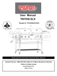
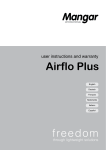
1
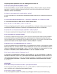
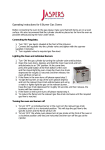
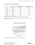
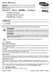
4 - 22.2 - 21 E - i - 1/08 Duct burners - "HC" AIRFLO® Installation and operating instructions Application requirements View port A view port to inspect burner flame is essential to inspect flame aspect. It is recommended to install the view port downstream of the flame, such that the entire burner front can be observed, as well as the pilot flame. The burner’s incorporated view port on the alternative UV-scanner connection only allows observation of flame presence but is not suitable to evaluate burner flame aspect. One or more separate view ports on the duct are always necessary. Required ancillary equipment Ensure that all required ancillary equipment for safe operation and correct performance of the "HC" AIRFLO® burner is installed, as described in the applicable local codes and/or process-related instructions. Position of the burner in the process flow MAXON "HC" AIRFLO® burners are designed for heating of process air in motion. They should be mounted so that they fire in the same direction as the flow of air. Refer to page 4-22.2-13 & page 4-22.2-14 to determine the correct process flow differential pressures accross the burners. This is essential for good burner performance. Do not mount the burner so that the movement of the process flow is across the face of the burner, nor should it be mounted too near to a duct which causes the process flow to be directed at an angle over the burner. Ensure that the process flow in the duct immediately upstream the burner is as uniform as possible. (max. deviation of process air velocity of approximately 5 % over 90 % of the area of a plane immediately in front of the burner.) Swirling, recirculating or reverse process air flowing at the burner front plane will dramatically reduce lifetime of the burner due to the risk of backfiring of the burner and overheating. Duct "HC" AIRFLO® burners have quite luminous and radiant flames which require special attention when designing duct parts covering the flame (combustion chamber). Especially in narrow ducts with flames close to the wall, it is essential to use correct materials and proper construction design. Refer to “Flame development and duct layout” section for more details. w w w . m a x o n c o r p . c o m combustion systems for industry MAXON reserves the right to alter specifications and data without prior notice. © 2007 Copyright Maxon Corporation. All rights reserved. Duct burners - "HC" AIRFLO® 4 - 22.2 - 22 E - i - 1/08 Installation Storage "HC" AIRFLO® burners should be stored dry (inside). Prevent that water and/or dust can penetrate into the burner manifold during storing. Handling "HC" AIRFLO® burners are shipped as complete units. Handle burner with care, using proper equipment during unpacking, transport, lifting and installation. Any impact on the burner could result in damage. Make use of the available lifting lugs on M and L type burners’ mounting plugs and the pipe-support at the opposite end of the burner for handling. When the burner elements are installed at an early stage and remain un-commissioned for a considerable long period, we advise to make additional precautions to protect the spark igniter and UV-scanner from damage. This can be done by temporarily removing these items and storing them in a dry place until date of commissioning. Flange the burner to the installation Each burner is equipped with a mounting plug. Bolt this mounting plug onto the combustion chamber’s burner mounting flange. Use proper gasket between burner mounting plug and combustion chamber’s flange. MAXON advises to use glass-fibre cord diam. 0.31 in., available as an option. Tighten the flange bolts with correct torque. Retighten all bolts after first firing and regularly after commissioning. Burner mounting flange dimension for type S burners The combustion chamber burner mounting flange is not included with the burner and should have the appropriate dimensions (refer to dimensional sketches below). Make sure that you have a standard MAXON "HC" AIRFLO® burner with standard mounting plug prior to combustion chamber mounting flange manufacturing. For special designed burners, refer to project specific construction drawings when applicable. Type S burners Type M and L burners Dimensions in in. unless stated otherwise Burner type A B C D E F ØG Type S 22 12.2 9.8 20 0.2 x 4 = 220 3 x 94 = 282 0.5 Type M and L 22 26.2 23.6 20 0.2 x 4 = 220 6 x 106.3 = 638 0.5 w w w . m a x o n c o r p . c o m combustion systems for industry MAXON reserves the right to alter specifications and data without prior notice. © 2007 Copyright Maxon Corporation. All rights reserved. 4 - 22.2 - 23 E - i - 1/08 Duct burners - "HC" AIRFLO® Mounting support Only use the "HC" AIRFLO® mounting support supplied by MAXON for supporting the burner at the opposite side of the mounting plug. The "HC" AIRFLO® mounting support is especially designed to give the burner sufficient flexibility during firing. Use of different kind of supports may damage or destroy the burner. Type M and type L burners have a support which is to be mounted in such a way that the weight of the burner is supported. This is only possible in one way, regardless the orientation of the burner. Type S burners have a different support. This support has to be mounted so that the burner weight is supported and burner is allowed to move backwards with thermal expansion. The position of the support bracket must be determined after installation of the burner element and must be positioned strictly in accordance with the typical installation sketches [1] and/or with the project drawings. Note that the bracket must always support the burner weight. The supporting arrangement must allow the burner element to move back freely. Due to thermal expansion the burner element will have the tendency to curve towards the upstream process air flow direction. All bolts and nuts on the supporting connection shall be checked and fastened after installation has been complete and must be tack welded to prevent them from spinning. [1] See sketches in section ‘burner orientation’ below for correct burner support mounting. Burner orientation MAXON advises to mount the "HC" AIRFLO® burner horizontally, with burner gas manifold in an horizontal plane. The burner can fire left, right, upwards or downwards or in any desired angle. Since all burners are symmetrical, it is not necessary to specify burner orientation when ordering. When burners are mounted vertically with mounting plug on top of the process air duct, special care should be taken to avoid excessive heating of accessories mounted on the mounting plate. Vertical mounting with mounting plug at the bottom of the process air duct is not advised because of dirt and/or moist build up in the UV-scanner tube. Burner type S 1 2 3 5 4 1) Firing down 4) Firing left 2) Firing up 5) Mounting support 3) Firing right Æ = movement of burner element when heated w w w . m a x o n c o r p . c o m combustion systems for industry MAXON reserves the right to alter specifications and data without prior notice. © 2007 Copyright Maxon Corporation. All rights reserved. Duct burners - "HC" AIRFLO® Burner type M 1 2 3 4 4) Firing up 1) Firing right 2) Firing left 5) Burner support 3) Firing down Æ = movement of burner element when heated Burner type L 1 2 5 4 3 1) Firing left 4) Firing down 2) Firing right 5) Mounting support 3) Firing up Æ = movement of burner element when heated w w w . m a x o n c o r p . c o m combustion systems for industry MAXON reserves the right to alter specifications and data without prior notice. © 2007 Copyright Maxon Corporation. All rights reserved. 5 4 - 22.2 - 24 E - i - 1/08 4 - 22.2 - 25 E - i - 1/08 Duct burners - "HC" AIRFLO® Start-up instructions Instructions provided by the company or individual responsible for the manufacture and/or overall installation of a complete system incorporating MAXON burners take precedence over the installation and operating instructions provided by MAXON. If any of the instructions provided by MAXON are in conflict with local codes or regulations, please contact MAXON before initial start-up of equipment. Read the combustion system manual carefully before initiating the start-up and adjustment procedure. Verify that all of the equipment associated with and necessary to the safe operation of the burner system has been installed correctly, that all pre-commissioning checks have been carried out successfully and that all safety related aspects of the installation are properly addressed. Initial adjustment and light-off should be undertaken only by a trained and authorized commissioning engineer. Safety interlocks Guarantee that all the required safety locks as described in the applicable local codes or regulations, or supplementary requested for safe operation of the overall installation, are working properly and resulting in a safety-lock of the burner. Do not bypass any of these safety interlocks, this will result in unsafe operation. Checks during and after start-up During and after start-up, check the integrity of the system. Check all bolted connections after first firing (first time on temperature) and retighten if necessary. Purge For safety-reasons, it is required to purge the installation sufficiently long to ensure that all possible combustibles are evacuated before ignition. Refer to the applicable local codes and your specific application requirements to determine the purge time. Pilot ignition Adjust pilot gas regulator to correct set point before pilot ignition attempt. Refine during lighting of the pilot to a yellow/blue flame and/or strongest stable flame signal Main burner ignition Ensure that the maximum allowed starting capacity is not exceeded when lighting the the main burner. High starting capacities can cause sudden increase of pressure in the duct system. Maximum capacity adjustment Once the main flame is ignited, adjust gas flow of the burner to obtain the required combustion quality. Slowly increase capacity while observing the flame. Especially observe that the flame is well divided over the entire burner length, and going straight forward in the direction of the process air flow. Check that no damage is caused to duct walls or other equipment. Adjust the max. capacity while observing the flame. Ensure that the burner is protected from over-firing in a safe way (for instance using mechanical stops in the gas control valve). Minimum capacity adjustment The burner should be protected from firing at too low capacity rates. Refer to page 4-22.2-8 for the minimum allowed capacities. Firing at low capacities will overheat the mixing plates and manifold. Therefore, minimum gas flow should always be guaranteed (for instance using a mechanical stop on minimum position on the gas control valve). w w w . m a x o n c o r p . c o m combustion systems for industry MAXON reserves the right to alter specifications and data without prior notice. © 2007 Copyright Maxon Corporation. All rights reserved. Duct burners - "HC" AIRFLO® 4 - 22.2 - 26 E - i - 1/08 Maintenance and inspection Safety requirements Regular inspection, testing and recalibration of combustion equipment according to the user manual is an integral part of its safety. Inspection activities and frequencies shall be carried out as specified in the user manual. Perform the following activities at least annually as part of a recommended preventative maintenance routine : Inspect burner internal parts for wear and oxidation. Inspect associated control instruments and devices for function with particular attention to all safety interlocks. Inspect tightness of mounting plug, screws and nuts. Visual inspections Regular visual inspection of all connections (air and gas piping to the burner, bolting of the burner mounting flange, mounting support in the duct) and burner flame shape and aspect are essential for safe operation. Recommended spare parts Keep local stock of spark igniter. It is not recommended to keep local stock of other burner parts. Consult user manual for burner spare pars and system accessories. Repair kits Standard repair kits are available to upgrade your burner when traces of wear start showing after several years of intensive use. These repair kits include all required bolts and nuts. Use this drawing for burner parts designation. 3 1) Pilot end plate 4 7 2) Plain end plate 6 2 3) Mixing plate 4) Back up bar 5) Deflector plate 6) Support bracket 5 7) Gas nozzle [1] 1 [1] gas nozzles are welded onto the burner manifold and are not available as separate spare parts. w w w . m a x o n c o r p . c o m combustion systems for industry MAXON reserves the right to alter specifications and data without prior notice. © 2007 Copyright Maxon Corporation. All rights reserved.