1
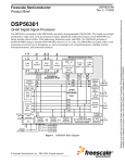
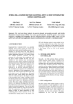
DSP56301ADM
User’s Manual
Motorola, Incorporated
Semiconductor Products Sector
Wireless Division
6501 William Cannon Drive West
Austin, TX 78735-8598
Order this document by:
DSP56301ADMUM/AD
Introduction
This document supports the DSP56301 Application Development Module
(DSP56301ADM), including a description of its basic structure and operation, the
equipment required to use it, the specifications of the key components, schematic
diagrams, and a parts list. Section 1 is a Quick Start Guide. Section 2 provides detailed
information about key components in the evaluation module. Appendix A has detailed
schematics.Appendix B lists the Bill Of Materials (BOM) for the board. Detailed
information is provided in the additional documents supplied with this kit.
OnCE and Mfax are trademarks of Motorola, Inc.
Motorola reserves the right to make changes without further notice to any products herein. Motorola makes no
warranty, representation or guarantee regarding the suitability of its products for any particular purpose, nor does
Motorola assume any liability arising out of the application or use of any product or circuit, and specifically disclaims
any and all liability, including without limitation consequential or incidental damages. “typical” parameters which may
be provided in Motorola data sheets and/or specifications can and do vary in different applications and actual
performance may vary over time. All operating parameters, including “Typicals” must be validated for each customer
application by customer’s technical experts. Motorola does not convey any license under its patent rights nor the rights
of others. Motorola products are not designed, intended, or authorized for use as components in systems intended for
surgical implant into the body, or other applications intended to support life, or for any other application in which the
failure of the Motorola product could create a situation where personal injury or death may occur. Should Buyer
purchase or use Motorola products for any such unintended or unauthorized application, Buyer shall indemnify and
hold Motorola and its officers, employees, subsidiaries, affiliates, and distributors harmless against all claims, costs,
damages, and expenses, and reasonable attorney fees arising out of, directly or indirectly, any claim of personal injury
or death associated with such unintended or unauthorized use, even if such claim alleges that Motorola was negligent
regarding the design or manufacture of the part. Motorola and
are registered trademarks of Motorola, Inc.
Motorola, Inc. is an Equal Opportunity/Affirmative Action Employer.
How to reach us:
USA/Europe/Locations Not Listed:
Motorola Literature Distribution
P.O. Box 5405
Denver, Colorado 80217
303-675-2140
1 (800) 441-2447
Asia/Pacific:
Motorola Semiconductors H.K. Ltd.
8B Tai Ping Industrial Park
51 Ting Kok Road
Tai Po, N.T., Hong Kong
852-26629298
Mfax™:
[email protected]
TOUCHTONE (602) 244-6609
Technical Resource Center:
1 (800) 521-6274
DSP Helpline
[email protected]
Japan:
Nippon Motorola Ltd.
Tatsumi-SPD-JLDC
6F Seibu-Butsuryu-Center
3-14-2 Tatsumi Koto-Ku
Tokyo 135, Japan
81-3-3521-8315
Internet:
http://www.motorola-dsp.com
TABLE OF CONTENTS
SECTION 1
QUICK START GUIDE. . . . . . . . . . . . . . . . . . . . . . . . .
1.1
OVERVIEW . . . . . . . . . . . . . . . . . . . . . . . . . . . . . . . . . . . . . . . .
1.2
EQUIPMENT . . . . . . . . . . . . . . . . . . . . . . . . . . . . . . . . . . . . . . .
1.2.1
What You Get with the DSP56301ADM . . . . . . . . . . . . . . . .
1.2.2
What You Need to Supply . . . . . . . . . . . . . . . . . . . . . . . . . . .
1.3
INSTALLATION PROCEDURE . . . . . . . . . . . . . . . . . . . . . . . . .
1.3.1
Preparing the DSP56301ADM. . . . . . . . . . . . . . . . . . . . . . . .
1.3.2
Connecting the DSP56301ADM to the PC and Power . . . . .
1.4
USING THE DSP56301ADM . . . . . . . . . . . . . . . . . . . . . . . . . . .
1-1
1-3
1-3
1-3
1-4
1-4
1-5
1-8
1-8
SECTION 2
DSP56301ADM TECHNICAL SUMMARY. . . . . . . . . . 2-1
2.1
DSP56301ADM DESCRIPTION AND FEATURES . . . . . . . . . . 2-3
2.2
DSP56301 DESCRIPTION . . . . . . . . . . . . . . . . . . . . . . . . . . . . 2-5
2.3
MEMORY . . . . . . . . . . . . . . . . . . . . . . . . . . . . . . . . . . . . . . . . . . 2-5
2.3.1
DRAM Selection . . . . . . . . . . . . . . . . . . . . . . . . . . . . . . . . . . 2-6
2.3.2
SRAM Selection. . . . . . . . . . . . . . . . . . . . . . . . . . . . . . . . . . . 2-6
2.3.3
Flash PROM Selection . . . . . . . . . . . . . . . . . . . . . . . . . . . . . 2-7
2.4
DSP56301 OPERATING MODE SELECTION. . . . . . . . . . . . . . 2-8
2.5
CLOCK SOURCE SELECTION . . . . . . . . . . . . . . . . . . . . . . . . . 2-9
2.5.1
On-Board Clock Generator Selection . . . . . . . . . . . . . . . . . 2-10
2.5.2
External Clock Selection . . . . . . . . . . . . . . . . . . . . . . . . . . . 2-10
2.5.3
Crystal Oscillator Selection . . . . . . . . . . . . . . . . . . . . . . . . . 2-10
2.5.4
DSP56301 PLL Enable/Disable On Reset. . . . . . . . . . . . . . 2-11
2.6
HOST PORT SELECTION . . . . . . . . . . . . . . . . . . . . . . . . . . . . 2-11
2.7
ISA DMA AND INTERRUPT CHANNELS . . . . . . . . . . . . . . . . 2-12
2.8
CONNECTORS . . . . . . . . . . . . . . . . . . . . . . . . . . . . . . . . . . . . 2-13
2.8.1
Expansion And Logic Analyzer Connectors. . . . . . . . . . . . . 2-13
2.8.2
5 V Power Connector. . . . . . . . . . . . . . . . . . . . . . . . . . . . . . 2-18
2.8.3
HI32 Connector . . . . . . . . . . . . . . . . . . . . . . . . . . . . . . . . . . 2-18
2.8.4
SSI Port Connectors . . . . . . . . . . . . . . . . . . . . . . . . . . . . . . 2-19
2.8.5
SCI Port Connector . . . . . . . . . . . . . . . . . . . . . . . . . . . . . . . 2-20
2.8.6
JTAG/OnCE Connector . . . . . . . . . . . . . . . . . . . . . . . . . . . . 2-21
MOTOROLA
DSP56301ADMUM/AD, Preliminary
iii
APPENDIX A
DSP56301ADM SCHEMATICS . . . . . . . . . . . . . . . . . A-1
APPENDIX B DSP56301ADM BILL OF MATERIALS . . . . . . . . . . . B-1
B.1
DSP56301ADM—ELECTRICAL PARTS LIST
REV. 2.1—3/15/95. . . . . . . . . . . . . . . . . . . . . . . . . . . . . . . . . . . B-3
B.2
DSP56301 ADM—HARDWARE PARTS LIST
REV. 2.1—3/15/95. . . . . . . . . . . . . . . . . . . . . . . . . . . . . . . . . . . B-5
iv
DSP56301ADMUM/AD, Preliminary
MOTOROLA
LIST OF FIGURES
Figure 1-1
DSP56301ADM Key Component Layout. . . . . . . . . . . . . . . . . . . . . . 1-6
Figure 1-2
Application Development. . . . . . . . . . . . . . . . . . . . . . . . . . . . . . . . . . 1-8
Figure 2-1
DSP56301ADM Functional Block Diagram . . . . . . . . . . . . . . . . . . . . 2-4
Figure 2-2
DSP56301ADM DRAM Interface. . . . . . . . . . . . . . . . . . . . . . . . . . . . 2-6
Figure 2-3
SRAM Connection . . . . . . . . . . . . . . . . . . . . . . . . . . . . . . . . . . . . . . . 2-7
Figure 2-4
Flash PROM Connection. . . . . . . . . . . . . . . . . . . . . . . . . . . . . . . . . . 2-8
Figure 2-5
DSP Mode Selection . . . . . . . . . . . . . . . . . . . . . . . . . . . . . . . . . . . . . 2-8
Figure 2-6
3.3 V Clock Generator Assembly . . . . . . . . . . . . . . . . . . . . . . . . . . 2-10
Figure 2-7
PLL Mode Selection . . . . . . . . . . . . . . . . . . . . . . . . . . . . . . . . . . . . 2-11
Figure 2-8
Expansion Connector (P10) . . . . . . . . . . . . . . . . . . . . . . . . . . . . . . 2-14
Figure 2-9
Expansion Connector (P12) . . . . . . . . . . . . . . . . . . . . . . . . . . . . . . 2-15
Figure 2-10
Expansion Connector (P5) . . . . . . . . . . . . . . . . . . . . . . . . . . . . . . . 2-16
Figure 2-11
Expansion Connector (P7) . . . . . . . . . . . . . . . . . . . . . . . . . . . . . . . 2-17
Figure 2-12
Dedicated SSI Connector (P3) . . . . . . . . . . . . . . . . . . . . . . . . . . . . 2-19
Figure 2-13
SSI - AIB Connector (P2) . . . . . . . . . . . . . . . . . . . . . . . . . . . . . . . . 2-20
Figure 2-14
SCI Dedicated Connector (P6) . . . . . . . . . . . . . . . . . . . . . . . . . . . . 2-21
Figure 2-15
JTAG/OnCE Connector (P4) . . . . . . . . . . . . . . . . . . . . . . . . . . . . . . 2-21
MOTOROLA
DSP56301ADMUM/AD, Preliminary
v
LIST OF TABLES
Table 1-1
DSP56301ADM Default Jumper Options . . . . . . . . . . . . . . . . . . . . . . 1-7
Table 2-1
DSP56301ADM Memories . . . . . . . . . . . . . . . . . . . . . . . . . . . . . . . . . 2-5
Table 2-2
DSP56301 Operating Mode Selection . . . . . . . . . . . . . . . . . . . . . . . . 2-9
Table 2-3
ISA Bus DMA Channel Configuration. . . . . . . . . . . . . . . . . . . . . . . . 2-12
Table 2-4
ISA Bus Interrupt Selection . . . . . . . . . . . . . . . . . . . . . . . . . . . . . . . 2-12
vi
DSP56301ADMUM/AD, Preliminary
MOTOROLA
SECTION 1
QUICK START GUIDE
MOTOROLA
DSP56301ADMUM/AD, Preliminary
1-1
Quick Start Guide
1.1
1.2
1.2.1
1.2.2
1.3
1.3.1
1.3.2
1.4
1-2
OVERVIEW . . . . . . . . . . . . . . . . . . . . . . . . . . . . . . . . . . . . . . . . .1-3
EQUIPMENT . . . . . . . . . . . . . . . . . . . . . . . . . . . . . . . . . . . . . . . .1-3
What You Get with the DSP56301ADM . . . . . . . . . . . . . . . . .1-3
What You Need to Supply. . . . . . . . . . . . . . . . . . . . . . . . . . . .1-4
INSTALLATION PROCEDURE . . . . . . . . . . . . . . . . . . . . . . . . . .1-4
Preparing the DSP56301ADM . . . . . . . . . . . . . . . . . . . . . . . .1-5
Connecting the DSP56301ADM to the PC and Power . . . . . .1-8
USING THE DSP56301ADM. . . . . . . . . . . . . . . . . . . . . . . . . . . .1-8
DSP56301ADMUM/AD, Preliminary
MOTOROLA
Quick Start Guide
Overview
1.1
OVERVIEW
The Motorola Application Development System (ADS) is a tool used to design and test
complex software applications and hardware products using a specific Motorola DSP
chip. The related Application Development Modules (ADMs) contain the DSP chip and
related hardware used for bench development and test. Detailed information about the
content and use of the ADS is provided in the ADS User’s Manual (order #
DSPADSUM/AD). This manual provides specific information about the DSP56301
Application Development Module (DSP56301ADM). This section provides a summary
description of the DSP56301ADM, additional requirements, and quick installation
information. Detailed information about the DSP56301ADM design and operation is
provided in the remaining sections of this manual.
1.2
EQUIPMENT
The following section gives a brief summary of the equipment required to use the
DSP56301 Application Development Module (DSP56301ADM), some of which will be
supplied with the module, and some of which must be supplied by the user.
1.2.1
What You Get with the DSP56301ADM
The following materials are provided with the DSP56301ADM:
• DSP56301 Application Development Module board
• DSP56301ADM Product Information
• DSP56301ADM User’s Manual (this document)
• Motorola Digital Signal Processor Registration Form
MOTOROLA
DSP56301ADMUM/AD, Preliminary
1-3
Quick Start Guide
Installation Procedure
1.2.2
What You Need to Supply
• Motorola Application Development System with appropriate host interface card
• Host Computer system:
–
PC-compatible computer (486 class or higher) with:
• MS-DOS version 6.0 or later or Windows 3.1 or later or Windows 95
• 8 Mbytes RAM
• one open 16-bit ISA or a PCI expansion slot
• free I/O addresses ($100–$102, $200–202, or $300–$303)
• CD-ROM drive
• hard drive with 4 Mbyte of free disk space
• mouse
1.3
–
Sun Microsystems Sun 4 Workstation running Sun Operating System Release
4.1.1 or later (or Solaris Release 2.5 or later), one open SBus expansion slot,
CD-ROM drive, and a mouse
–
Hewlett Packard HP7xx Workstation running HPUX Version 9.x (Version 10.x
is not supported), one open EISA expansion slot, CD-ROM drive, and a mouse
INSTALLATION PROCEDURE
Installation requires the following steps:
1. Using information provided in the Motorola ADS User’s Manual, install the
Motorola Application Development System in the host computer.
2. Prepare the DSP56301ADM board
3. Connect the board to the external Command Converter card
1-4
DSP56301ADMUM/AD, Preliminary
MOTOROLA
Quick Start Guide
Installation Procedure
1.3.1
Preparing the DSP56301ADM
CAUTION
Because all electronic components are sensitive to the effects of
electrostatic discharge (ESD) damage, correct procedures should be
used when handling all components in this kit and inside the
supporting personal computer. Use the following procedures to
minimize the likelihood of damage due to ESD:
– Always handle all static-sensitive components only in a protected
area, preferably a lab with conductive (anti-static) flooring and
bench surfaces.
– Always use grounded wrist straps when handling sensitive
components.
– Never remove components from anti-static packaging until
required for installation.
– Always transport sensitive components in anti-static packaging.
Locate the fourteen jumper blocks JP1–JP14 and switch block SW2 on the
DSP56301ADM board, as shown in Figure 1-1 on page 1-6. Table 1-1 describes the
default jumper and switch settings when shipped from the factory.
Read the technical summary in Section 2 of this manual for additional information
about the DSP56301ADM board and its components.
MOTOROLA
DSP56301ADMUM/AD, Preliminary
1-5
Quick Start Guide
Installation Procedure
OFF
ON
Note: 5 V is on side
closest to switch.
Figure 1-1 DSP56301ADM Key Component Layout
1-6
DSP56301ADMUM/AD, Preliminary
MOTOROLA
Quick Start Guide
Installation Procedure
Table 1-1 DSP56301ADM Default Jumper Options
Jumper/Switch
Block
Default Configuration as Shipped
Comment
JP1
Jumpered
Enable SRAM memory
JP2
Jumpered
Enable DRAM memory
JP3
Jumpered
Enable Flash memory
JP4,JP5, JP6, JP7
Jumpered
Enable ISA host interface
JP8,JP10
JP8—No jumpers
JP10—Pins 3–6 and 4–5 jumpered
Set ISA DMA channel 5
JP9
Pins 1–2 jumpered
Set ISA clamp protection
JP11
Pins 4–5 jumpered
Set ISA Interrupt channel 10
JP12
Removed
Enable DSP PLL operation
JP13,JP14
JP13 Removed
JP14 Pins 2–5 jumpered
Set clock source to clock generator.
SW2
SW2–1: Off
SW2–2: On
SW2–3: Off
Bootstrap from HOST ISA
Note:
The factory default configuration selects ISA bus operation for the plug-in card feature. Refer to
Section 2.6 Host Port Selection for other available port configurations.
MOTOROLA
DSP56301ADMUM/AD, Preliminary
1-7
Quick Start Guide
Using the DSP56301ADM
1.3.2
Connecting the DSP56301ADM to the PC and Power
Figure 1-2 shows the interconnection diagram for connecting the PC and the external
power supply to the DSP56301ADM board. Using the instructions in the ADS User’s
Manual, connect the Command Converter to the ADM board. Power for the ADM is
supplied from the Command Converter module.
37-pin
Interface
Cable
User Application
Circuits
14-pin
Ribbon
Cable
Host Computer
Motorola DSP
Host-Bus
Interface Card
Command
Converter
Application Development Module (ADM)
Figure 1-2 Application Development
1.4
USING THE DSP56301ADM
Once the ADM is installed, it becomes a part of the Application Development System.
Use information in the Application Development System User’s Manual to develop your
application design, debug it, and test it.
1-8
DSP56301ADMUM/AD, Preliminary
MOTOROLA
SECTION 2
DSP56301ADM TECHNICAL SUMMARY
MOTOROLA
DSP56301ADMUM/AD, Preliminary
2-1
DSP56301ADM Technical Summary
2.1
2.2
2.3
2.3.1
2.3.2
2.3.3
2.4
2.5
2.5.1
2.5.2
2.5.3
2.5.4
2.6
2.7
2.8
2.8.1
2.8.2
2.8.3
2.8.4
2.8.5
2.8.6
2-2
DSP56301ADM DESCRIPTION AND FEATURES . . . . . . . . . . .2-3
DSP56301 DESCRIPTION . . . . . . . . . . . . . . . . . . . . . . . . . . . . .2-5
MEMORY. . . . . . . . . . . . . . . . . . . . . . . . . . . . . . . . . . . . . . . . . . .2-5
DRAM Selection . . . . . . . . . . . . . . . . . . . . . . . . . . . . . . . . . . .2-6
SRAM Selection . . . . . . . . . . . . . . . . . . . . . . . . . . . . . . . . . . .2-6
Flash PROM Selection . . . . . . . . . . . . . . . . . . . . . . . . . . . . . .2-7
DSP56301 OPERATING MODE SELECTION . . . . . . . . . . . . . .2-8
CLOCK SOURCE SELECTION. . . . . . . . . . . . . . . . . . . . . . . . . .2-9
On-Board Clock Generator Selection . . . . . . . . . . . . . . . . . .2-10
External Clock Selection . . . . . . . . . . . . . . . . . . . . . . . . . . . .2-10
Crystal Oscillator Selection . . . . . . . . . . . . . . . . . . . . . . . . . .2-10
DSP56301 PLL Enable/Disable On Reset . . . . . . . . . . . . . .2-11
HOST PORT SELECTION . . . . . . . . . . . . . . . . . . . . . . . . . . . .2-11
ISA DMA AND INTERRUPT CHANNELS . . . . . . . . . . . . . . . . .2-12
CONNECTORS . . . . . . . . . . . . . . . . . . . . . . . . . . . . . . . . . . . . .2-13
Expansion And Logic Analyzer Connectors . . . . . . . . . . . . .2-13
5 V Power Connector . . . . . . . . . . . . . . . . . . . . . . . . . . . . . .2-18
HI32 Connector . . . . . . . . . . . . . . . . . . . . . . . . . . . . . . . . . . .2-18
SSI Port Connectors . . . . . . . . . . . . . . . . . . . . . . . . . . . . . . .2-19
SCI Port Connector . . . . . . . . . . . . . . . . . . . . . . . . . . . . . . . .2-20
JTAG/OnCE Connector. . . . . . . . . . . . . . . . . . . . . . . . . . . . .2-21
DSP56301ADMUM/AD, Preliminary
MOTOROLA
DSP56301ADM Technical Summary
DSP56301ADM Description and Features
2.1
DSP56301ADM DESCRIPTION AND FEATURES
The DSP56301ADM is designed as a versatile card that can be used not only as a
stand-alone board, but can also be plugged into other cards. Four 50-pin connectors
allow access to all the DSP signals, including VDD and VSS. This plug-in feature permits
special configurations, including, among others, connection to a customized
wire-wrapped or other application board to permit enhanced functionality. An overview
description of the DSP56301ADM is also provided in the DSP56301ADM Product
Information document (order number DSP56301ADMP/D) included with this kit.
The main features of the DSP56301ADM include the following:
• DSP56301 24-bit Digital Signal Processor
• 32 K Word FSRAM with 12 ns access (5 V)
• 64 K Byte Flash PROM Memory, 200 ns access on-board (3 V) programmable
• 512 K Word DRAM, 70 ns access.
• ISA bus compatible edge-connector (slave only operation).
• PCI bus compatible edge-connector (master & slave operation).
• Table mounted (stand-alone) operation, or computer plug-in card operation.
• Integrated Expansion and Logic-Analyzer Connectors.
• Dedicated SSI and SCI port connectors.
• JTAG/OnCE port connector for easy hookup to Motorola command converter
• 5 V operation, with on board 3.3 V voltage regulation.
• Power terminals and 8-pin clock socket for stand-alone operation.
Note:
Call your local Motorola sales office or distributor for additional information
about the Motorola Application Development System (ADS) kit. The ADS kit
includes two additional boards: a host interface card and an external universal
command converter. The host interface card plugs in the host bus (on a
PC-compatible, HP7xx workstation, or Sun/Sun-compatible system) inside
the computer chassis. The external universal command converter card
connects to the host card via a 37-pin ribbon cable. The command converter
card connects to the JTAG connector on the DSP56301ADM via another short
14-pin ribbon cable. The ADS is only compatible with Motorola software tools.
MOTOROLA
DSP56301ADMUM/AD, Preliminary
2-3
DSP56301ADM Technical Summary
DSP56301ADM Description and Features
Expansion & Logic Analyzer Connectors
Reset
Clock Gen.
& Mode sel.
DSP56301
64 K X 8
Flash PROM (3 V)
AT29LV512 (ATMEL)
32 K × 24
Static RAM
MCM6706AJ12
3 V <-> 5 V
PORT A
HI32 PORT
SCI PORT
Signals
buffers
512 K × 24
DRAM
MCM54800AJ70
SSI PORTS
ISA Edge Connector
JTAG/OnCE
PCI Edge Connector
JTAG/OnCE
Connector
SCI Port
SSI0 and SSI1 Port & AIB I/F
5 V to 3 V voltage
regulator
Figure 2-1 DSP56301ADM Functional Block Diagram
2-4
DSP56301ADMUM/AD, Preliminary
MOTOROLA
DSP56301ADM Technical Summary
DSP56301 Description
2.2
DSP56301 DESCRIPTION
A full description of the DSP56301, including functionality and user information is
provided in the following documents included as a part of this kit (either as printed
copies or on the documentation CD-ROM):
• DSP56301 Technical Data—Provides features list and specifications including
signal descriptions, DC power requirements, AC timing requirements, and
available packaging
• DSP56301 User’s Manual—Provides an overview description of the DSP and
detailed information about the on-chip components including the memory and
I/O maps, peripheral functionality, and control and status register descriptions
for each subsystem
• DSP56300 Family Manual—Provides a detailed description of the core processor
including internal status and control registers and a detailed description of the
family instruction set
Refer to these documents for detailed information about chip functionality and
operation.
2.3
MEMORY
Table 2-1 lists the memory used in the DSP56301ADM.
Table 2-1 DSP56301ADM Memories
TYPE
SIZE
SPEED
AA line (used as chip select)
DRAM
512 K Word
70 ns
AA3
SRAM
32 K Word
12 ns
AA0
Flash PROM
64 K Byte
200 ns
AA1
MOTOROLA
DSP56301ADMUM/AD, Preliminary
2-5
DSP56301ADM Technical Summary
Memory
2.3.1
DRAM Selection
The DSP56301ADM uses a single bank of three 512 K × 8, 70 ns, 5 V-only DRAMs
(Motorola MCM54800AJ70). The DRAM is accessed by the DSP56301 using 3 wait-cycles
during Page mode (not including the RAS precharge time at a beginning of a new page)
and 11 wait-cycles in a non-page access, when the DSP operates at 66MHz. Address bus
load capacitance from this configuration is 5 pF × 3, or 15 pF per address line. Data bus
load capacitance is 7 pF. The AA3 (Address Attribute) signal is used as a Row Address
Strobe (RAS) and Chip Enable (CE) line. The design uses the SOJ package to achieve
greatest space reduction. DRAM refresh is provided by the DSP56301 DRAM controller.
The DRAM connection is illustrated in Figure 2-2.
MCM54800AJ70
A0–A9
A0–A9
A0–A9
A0–A9
AA3/RAS
RAS
RAS
RAS
CAS
WR
CAS
CAS
CAS
W
W
W
RD
G
G
G
DQ0–DQ7
D0–D23
DQ0–DQ7
D16–D23
DQ0–DQ7
D8–D15
D0–D7
Figure 2-2 DSP56301ADM DRAM Interface
Note:
2.3.2
The DRAM memory is enabled/disabled using jumper JP2. When JP2 is
placed, the DRAM is enabled. When JP2 is removed, the DRAM is disabled,
and the user may use AA3 for other purposes.
SRAM Selection
Three Motorola MCM6706AJ12 SRAMs are used to optimize performance. These
SRAMs are 32 K × 8, Bi CMOS, 5 V-only devices with an access time of 12 ns. Address
bus load capacitance in this configuration is 5 pF × 3, or 15 pF per address line. Data bus
load capacitance is 6 pF. The SRAM is accessed by the DSP56301 with 1 wait-state when
the DSP operates at 66MHz clock. The chip-select signal for the SRAM is generated using
the DSP56301 AA0 line. The MCM6706AJ12 SRAM uses 5 V input power. Connection to
the SRAM is shown in Figure 2-3 on page 2-7.
2-6
DSP56301ADMUM/AD, Preliminary
MOTOROLA
DSP56301ADM Technical Summary
Memory
MCM6706AJ12
A0–A14
A0–A14
A0–A14
A0–A14
WR
AA0
RD
W
E
W
E
W
E
G
DQ0–DQ7
D16–D23
G
DQ0–DQ7
G
DQ0–DQ7
D0–D23
D8–D15
D0–D7
Figure 2-3 SRAM Connection
Note:
2.3.3
The SRAM memory is enabled/disabled using jumper JP1.When JP1 is placed,
the SRAM is enabled. When JP1 is removed, the SRAM is disabled, and the
user may use AA0 for other purposes.
Flash PROM Selection
The DSP56301ADM includes a Flash PROM to facilitate stand-alone operation. The
FPROM is on-board and programmable, making it ideal for programming updates. The
DSP56031ADM uses a programmable, byte-wide, AT29LV512, 3 V-only (eliminating the
need for additional supply or a DC-DC converter) FPROM with 200 ns access time. The
load capacitance of this chip is 6 pF on the address lines and 12 pF max on the data lines.
The Flash memory may tolerate up to 1000 program cycles per sector (each sector is 128
bytes—total of 512 sectors).
The AT29LV512 has a low-power write-protect feature to guard against inadvertent
writes during power transitions. The FPROM also permits data polling during
programming to shorten programming cycles. Figure 2-4 on page 2-8 illustrates the
DSP56301 hookup to a byte wide non-volatile memory. All actions to the device are
controlled via a sequence of commands written to the device.
MOTOROLA
DSP56301ADMUM/AD, Preliminary
2-7
DSP56301ADM Technical Summary
DSP56301 Operating Mode Selection
29F010-12
A0–A16
A0–A16
WR
WE
RD
OE
AA1
CE
DQ0–DQ7
D0–D7
Figure 2-4 Flash PROM Connection
Note:
2.4
The Flash memory is enabled/disabled using jumper JP3. When JP3 is placed,
the Flash is enabled. When JP3 is removed, the Flash memory is disabled, and
the user may use AA1 for other purposes.
DSP56301 OPERATING MODE SELECTION
Support is provided to enable the DSP56301 to enter one of six possible operating modes
(two additional modes are reserved), via MODA/IRQA–MODC/IRQC and NMI/PINIT
lines.These lines are sampled by the DSP56301 on the rising edge of RESET line and the
sampled combination is moved to the OMR (Operating Mode Reg.). Figure 2-5
illustrates the mode selection on the deassertion of the RESET signal. After reset, the
mode selection lines are driven by pull-up resistors. JP12 is connected to the NMI/PINIT
line.
RESET
QS3244SO (2 to 1 MUX)
INTERRUPT REQUESTS
1
TO DSP56301
INIT MODE SELECT
0
Figure 2-5 DSP Mode Selection
2-8
DSP56301ADMUM/AD, Preliminary
MOTOROLA
DSP56301ADM Technical Summary
Clock Source Selection
Table 2-2 DSP56301 Operating Mode Selection
MODE
SW2(1)
SW2(2)
SW2(3)
0—Expanded mode
On
On
On
1—Bootstrap from byte-wide FLASH
Off
On
On
2—Bootstrap through SCI
On
Off
On
3—Reserved
Off
Off
On
4—Host Bootstrap PCI mode (32-bit-wide)
On
On
Off
5—Host Bootstrap ISA Mode (16-bit-wide)
Off
On
Off
6—Host Bootstrap UB Mode (8-bit-wide)
On
Off
Off
7 —Reserved
Off
Off
Off
After the RESET line is released (high) the MOD/IRQ signals are connected to IRQA,
IRQB, and IRQC signals.
2.5
CLOCK SOURCE SELECTION
There are 3 clock sources to the DSP56301:
• On-board 33MHz clock generator, supplied from factory
• External BNC connector
• Crystal Oscillator
Note:
When either of the first two options are used, set bits XTLD and COD in the
PLL Control Register (PCTL) to disable unnecessary clock signals and avoid
unnecessary on-board radio frequency emissions.
MOTOROLA
DSP56301ADMUM/AD, Preliminary
2-9
DSP56301ADM Technical Summary
Clock Source Selection
2.5.1
On-Board Clock Generator Selection
The clock generator is socketed to allow easy replacement with different frequency clock
generators. The board is supplied with a 33 MHz clock generator. The PCB layout is
designed so that either a 14-pin DIP packages or an 8-pin DIP packages may be accepted.
The clock generator should be placed in the socket as shown in Figure 2-6. To select the
on-board clock generator, JP13 should not be jumpered, and JP14 should be jumpered
from pin 2 to pin 5. The DSP56301ADM comes with aDIP14 package 33 MHz clock
generator.
14
13
12
DIP14 PACKAGE
11
10
9
8
8
7
6
5
Note:
Pin 8 of 14-pin socket or
Pin 5 of the 8-pin socket is
clock out.
DIP8 PACKAGE
1
2
3
4
U15 socket
1
2
3
4
5
6
7
Figure 2-6 3.3 V Clock Generator Assembly
2.5.2
External Clock Selection
To support non-standard clock rates and frequency fine tuning, the DSP56301ADM
provides a 50 Ω impedance, DC-coupled, BNC connector for a 3.3 V clock input. To
select the external clock generator, JP13 should not be jumpered, and JP14 should be
jumpered from pin 3 to pin 4.
Note:
2.5.3
For proper operation, the external clock must have rise/fall times < 3 ns.
Crystal Oscillator Selection
By using a low-frequency crystal oscillator, the user can reduce external high frequency
emissions, while still allowing the the DSP56301 to run at higher operating frequencies
generated by the on-chip PLL. The crystal must have bypass capacitors at both ends.
When the crystal oscillator is used, the user should install appropriately rated
components C32,C33,R16,R17 and Y1 (See the DSP56301 Technical Data sheet for more
information). To enable the on-board crystal oscillator, place a jumper on JP13 and
another jumper across pins 1–6 on JP14.
Note:
2-10
Power should be turned off prior to inserting/removing the crystal oscillator.
DSP56301ADMUM/AD, Preliminary
MOTOROLA
DSP56301ADM Technical Summary
Host Port Selection
2.5.4
DSP56301 PLL Enable/Disable On Reset
The DSP56301 samples the PINIT/NMI line on exit from the reset state to determine
whether the PLL should be enabled or disabled. To enable the PLL, JP12 should be
jumpered. To disable the PLL, JP12 pins 1-2 should be jumpered.
RESET
QS3244SO (2 to 1 MUX)
NMI Requests
1
To DSP56301
PLL INIT jumper
0
Figure 2-7 PLL Mode Selection
After the RESET line is deasserted the PINIT/NMI signal is connected to the NMI signal.
Note:
2.6
The ADM is factory configured for PLL enabled (JP12 removed).
HOST PORT SELECTION
The DSP56301’s HI32 port directly supports a PCI bus interface. Connection to an ISA
bus interface requires the addition of external buffers. The DSP56301ADM supports
application development for either bus by providing both a PCI edge connector and an
ISA edge connector (with the appropriate buffers).
When the DSP56301ADM is used with ISA host, place a jumper across JP4, JP5, JP6, and
JP7 with the components U16, U17, U18, U19, U20, RN1, and RN2 mounted in their
sockets. When the ADM is used in PCI host or as a stand-alone device, there should be
no jumpers on JP4, JP5, JP6, and JP7 and the components in U16, U17, U18, U19, U20,
RN1, and RN2 should be removed.
Note:
The ADM is factory configured for ISA Host Mode.
MOTOROLA
DSP56301ADMUM/AD, Preliminary
2-11
DSP56301ADM Technical Summary
ISA DMA and Interrupt Channels
2.7
ISA DMA AND INTERRUPT CHANNELS
The ADM enables the user to configure one of four channels for DMA and one of four
interrupt channels for an ISA bus interface. Table 2-3 and Table 2-4 describe these
configurations options.
Table 2-3 ISA Bus DMA Channel Configuration
DMA Channel
JP8
JP10
0
None
1–8, 2–7
5
None
3–6, 4–5
6
3–6, 4–5
None
7
1–8, 2–7
None
Table 2-4 ISA Bus Interrupt Selection
2-12
Interrupt
JP11
5
3–6
6
2–7
7
1–8
10
4–5
DSP56301ADMUM/AD, Preliminary
MOTOROLA
DSP56301ADM Technical Summary
Connectors
2.8
CONNECTORS
The DSP56301ADM includes the following connectors:
• Expansion and Logic-Analyzer connector—four 2 × 25-pin SMD pin-rows
• Power—2-pin terminal block, two-part
• HI32 port—ISA and PCI edge connectors
• SSI I/F—Two connectors: 2 × 7 and 2 × 15 SMD pin-rows
• JTAGE/OnCE port connector—2 × 7 SMD pin-rows
2.8.1
Expansion And Logic Analyzer Connectors
The DSP56301ADM has a set of four dual-in-line 50-pin SMD pin rows connectors to
support both hardware expansion and logic-analyzer connection. These connectors are
connected to all the pins of the DSP56301 chip except for the PCAP, XTAL, EXTAL,
MODA, MODB, MODC, and PINIT. All the other DSP56301 pins are routed to these
connectors along with +3.3 V and GND pins. The power and ground pins facilitate
hardware expansions powered by the DSP56301ADM. Figure 2-8 on page 2-14,
Figure 2-9 on page 2-15, Figure 2-10 on page 2-16, and Figure 2-11 on page 2-17 show
the pinouts for these connectors.
MOTOROLA
DSP56301ADMUM/AD, Preliminary
2-13
DSP56301ADM Technical Summary
Connectors
BCLK
1
2
AA1
V3.3
3
4
GND
CLKOUT
5
6
AA0
CAS
7
8
TA
NMI
9
10
RESET
V3.3
11
12
V3.3
GND
13
14
GND
BB
15
16
BG
BR
17
18
V3.3
GND
19
20
AA2
AA3
21
22
WR
RD
23
24
GND
V3.3
25
26
V3.3
GND
27
28
SPARE2
A0
29
30
A8
GND
31
32
V3.3
A1
33
34
A9
A2
35
36
A10
GND
37
38
V3.3
A3
39
40
A11
A4
41
42
A12
GND
43
44
V3.3
A5
45
46
A13
A6
47
48
A14
A7
49
50
A15
Figure 2-8 Expansion Connector (P10)
2-14
DSP56301ADMUM/AD, Preliminary
MOTOROLA
DSP56301ADM Technical Summary
Connectors
IRQB
1
2
IRQA
D22
3
4
D23
D21
5
6
V3.3
GND
7
8
D20
D18
9
10
D19
D16
11
12
D17
D15
13
14
V3.3
GND
15
16
D14
D12
17
18
D13
D10
19
20
D11
D9
21
22
V3.3
GND
23
24
V3.3
GND
25
26
D8
D6
27
28
D7
D4
29
30
D5
D3
31
32
V3.3
GND
33
34
D2
D0
35
36
D1
A22
37
38
A23
V3.3
39
40
V3.3
A20
41
42
A21
A18
43
44
A19
V3.3
45
46
V3.3
A16
47
48
A17
GND
49
50
GND
Figure 2-9 Expansion Connector (P12)
MOTOROLA
DSP56301ADMUM/AD, Preliminary
2-15
DSP56301ADM Technical Summary
Connectors
GND
1
2
GND
BL
3
4
BS
STD0
5
6
SC10
TDI
7
8
TCK
TMS
9
10
TDO
SC20 11
12
DEZ
SC00 13
14
TRST
GND 15
16
V3.3
SCK0 17
18
SRD1
SRD0 19
20
SCK1
SC21 21
22
STD1
SC11 23
24
SC01
TXD 25
26
GND
V3.3 27
28
SPARE1
GND 29
30
V3.3
SCLK 31
32
RXD
TIO0 33
34
TIO1
TIO2 35
36
HAD0
HAD1 37
38
HAD2
HAD3 39
40
V3.3
GND 41
42
HAD4
HAD5 43
44
HAD6
HAD7 45
46
HC0
HAD8 47
48
HAD9
HAD10 49
50
HAD11
Figure 2-10 Expansion Connector (P5)
2-16
DSP56301ADMUM/AD, Preliminary
MOTOROLA
DSP56301ADM Technical Summary
Connectors
V3.3
1
2
GND
HAD12
3
4
HAD13
HAD14
5
6
HAD15
HRST
7
8
HC1
HCLK
9
10 HAEN
HREQ 11
12 HPAR
V3.3 13
14 GND
HIRQ 15
16 HWR
HLOCK 17
PVCL 19
GND 21
HTRDY 23
18 HDRQ
20 HDEVSEL
22 V3.3
24 HFRAME
GND 25
26 V3.3
HIRDY 27
28 HRD
HC2 29
30 HAD16
HAD18 31
32 HAD17
HAD19 33
34 GND
V3.3 35
36 HAD20
HAD21 37
38 HAD22
HAD23 39
40 HC3
HAD24 41
42 HAD25
HAD26 43
44 HAD27
HAD28 45
46 HAD29
HAD30 47
48 HAD31
IRQD 49
50 IRQC
Figure 2-11 Expansion Connector (P7)
MOTOROLA
DSP56301ADMUM/AD, Preliminary
2-17
DSP56301ADM Technical Summary
Connectors
2.8.2
5 V Power Connector
The 5 V power connector to the DSP56301ADM is a 2-lead terminal block next to the
power switch SW1. The power connector and power switch are only used for
stand-alone operation; the power switch SW1 is used to turn the ADM on or off.
2.8.3
HI32 Connector
There are two HI32 connectors on the DSP56301ADM:
1. PCI edge connector, configured as 32-bit universal (5 V & 3.3 V) connector
2. ISA edge connector
These connectors are located on opposite sides of the DSP56301ADM, enabling it to
operate using an ISA, EISA, or PCI bus interface. The PCI edge connector is keyed with
both 5 V and 3.3 V keys to permit operation with either 5 V or 3.3 V PCI-backplanes.
2-18
DSP56301ADMUM/AD, Preliminary
MOTOROLA
DSP56301ADM Technical Summary
Connectors
2.8.4
SSI Port Connectors
The SSI port pins appear on three different connectors:
• The Expansion & Logic-Analyzer connectors
• Two dedicated SSI port connectors
• DSP56004 Audio Interface Bus (AIB) compatible connector
The SSI pins are multiplexed to these connectors to permit connection of the SSI pins to
various applications. The dedicated general purpose connectors are for general purpose
use to be connected via a ribbon cable to another board. To avoid crosstalk and supply
concurrent impedance path for the ongoing signals, GND lines are inserted between the
signal lines. To avoid incorrect insertion of the receptacle connector, keying is provided
as pin 13 is cut while its corresponding hole in the receptacle connector is filled. The
pinout of the independent SSI connector is shown in Figure 2-12
SRD1
1
2
GND
STD1
3
4
GND
SC01
5
6
GND
SC11
7
8
GND
SC21
9
10 GND
SCK1 11
12 GND
KEY 13
14 GND
Figure 2-12 Dedicated SSI Connector (P3)
The AIB interface connector is meant to support the DSP56004 Audio Interface Board
(AIB), a high-quality audio board with two stereo 18-bit ADCs and three stereo 18-bit
DACs, originally designed to for the DSP56004. The pinout of the SSI-AIB connector is
shown in Figure 2-13 on page 2-20. In the figure, the leftmost column contains the AIB
connector signal names, while the next column contains the DSP56301 signal names. The
DSP56301ADM supports one stereo output channel and one stereo input channel when
connected to the AIB.
MOTOROLA
DSP56301ADMUM/AD, Preliminary
2-19
DSP56301ADM Technical Summary
Connectors
AIB Function
GPIO0
SRD1
1
2
GND
GPIO1
STD1
3
4
GND
GPIO2
SC01
5
6
GND
GPIO3
SC11
7
8
GND
SDI0
SRD0
9
10
GND
SDI1
N.C.
11
12
GND
RBICK
SC00
13
14
GND
RLRCK
SC10
15
16
GND
SDO0
STD0
17
18
GND
SDO1
N.C
19
20
GND
SDO2
N.C
21
22
GND
TBICK
SCK0
23
24
GND
TLRCK
SC20
25
26
GND
RESET
RESET
27
28
GND
GND
29
30
GND
GND
This connector
is not on ADM
Figure 2-13 SSI - AIB Connector (P2)
2.8.5
SCI Port Connector
The SCI port pins are routed to two connectors:
• The Expansion & Logic-Analyzer connectors
• Dedicated SCI port connector
Routing to the expansion Logic-Analyzer connectors is done to support expansion
boards and application debugging. The dedicated connector attaches to an application
board via a ribbon cable. To avoid incorrect insertion of the plug into the receptacle,
keying is provided via pin 6, which is cut, while its corresponding hole in the receptacle
connector is filled.
2-20
DSP56301ADMUM/AD, Preliminary
MOTOROLA
DSP56301ADM Technical Summary
Connectors
The pinout of the SCI dedicated connector is shown in Figure 2-14.
TXD
1
2
GND
SCLK
3
4
GND
RXD
5
6
KEY
Figure 2-14 SCI Dedicated Connector (P6)
2.8.6
JTAG/OnCE Connector
The JTAG/OnCE connector is used both for JTAG testing during production, and for
OnCE functions for code debugging and software development.The pinout of the
JTAG/OnCE dedicated connector is shown in Figure 2-15.
TDI
1
2 GND
TDO
3
4 GND
TCK
5
6 GND
DR
7
8 KEY
ORESET
9
10 TMS
VDD 11
12 TMS1
DEZ 13
14 TRST
Figure 2-15 JTAG/OnCE Connector (P4)
MOTOROLA
DSP56301ADMUM/AD, Preliminary
2-21
DSP56301ADM Technical Summary
Connectors
2-22
DSP56301ADMUM/AD, Preliminary
MOTOROLA
APPENDIX A
DSP56301ADM SCHEMATICS
MOTOROLA
DSP56301ADMUM/AD
A-1
DSP56301ADM Schematics
A-2
DSP56301ADMUM/AD
MOTOROLA
A
B
C
D
137
134
133
138
140
145
141
149
146
142
139
129
130
148
147
181
28
PVCL
HTRDY*
HIRDY*
HDEVSEL*
HLOCK
HPAR
HDRQ
HAEN
HREQ*
HIRQ
HWR*
HRD*
HFRAME*
HCLK
HRST
HINTA
SPARE2
8
163
150
128
117
173
172
171
170
167
166
165
164
162
161
160
159
154
153
152
151
127
126
125
124
121
120
119
118
116
115
114
113
110
109
108
107
HC<0>
HC<1>
HC<2>
HC<3>
HAD<0>
HAD<1>
HAD<2>
HAD<3>
HAD<4>
HAD<5>
HAD<6>
HAD<7>
HAD<8>
HAD<9>
HAD<10>
HAD<11>
HAD<12>
HAD<13>
HAD<14>
HAD<15>
HAD<16>
HAD<17>
HAD<18>
HAD<19>
HAD<20>
HAD<21>
HAD<22>
HAD<23>
HAD <24>
HAD <25>
HAD <26>
HAD <27>
HAD <28>
HAD <29>
HAD <30>
HAD <31>
8
7
HINTA
SPARE2
PVCL
HTRDY*_HDBEN*
HIRDY*_HDBDR*
HDEVSEL*_HSAK*
HLOCK*_HBS*
HPARHDAK*
HPERR*_HDRQ
HGNT*_HAEN
HREQ*_HTA*
HSERR*_HIRQ
HSTOP*_HWR*
HIDSEL_HRD*
HFRAME*
HCLK
HRST*_HRST
HAD<0>
HAD<1>
HAD<2>
HAD<3>
HAD<4>
HAD<5>
HAD<6>
HAD<7>
HAD<8>
HAD<9>
HAD<10>
HAD<11>
HAD<12>
HAD<13>
HAD<14>
HAD<15>
HAD<16>
HAD<17>
HAD<18>
HAD<19>
HAD<20>
HAD<21>
HAD<22>
HAD<23>
HAD<24>
HAD<25>
HAD<26>
HAD<27>
HAD<28>
HAD<29>
HAD<30>
HAD<31>
HC<0>_HBE0*
HC<1>_HBE1*
HC<2>_HBE2*
HC<3>_HBE3*
U12
7
6
5
A<0>
A<1>
A<2>
A<3>
A<4>
A<5>
A<6>
A<7>
A<8>
A<9>
A<10>
A<11>
A<12>
A<13>
A<14>
A<15>
A<16>
A<17>
A<18>
A<19>
A<20>
A<21>
A<22>
A<23>
29
30
33
34
35
36
39
40
41
42
45
46
47
48
51
52
55
56
59
60
61
62
65
66
DSP56301
WR*
RD*
CAS*
TA*
BR*
BG*
BB*
BL*
BS*
DE*
TRST*
TCK
TDI
TDO
TMS
SC00
SC01
SC02
STD0
SRD0
SCK0
SC10
SC11
SC12
STD1
SRD1
SCK1
TXD
RXD
SCLK
TIO0
TIO1
TIO2
BCLK
CLKOUT
EXTAL
XTAL
PINIT
RESET*
22
23
7
8
17
16
15
206
205
199
204
201
202
203
200
196
197
198
195
191
192
187
186
185
188
190
189
184
177
178
176
175
174
6
5
26
24
10
9
12
WR*
RD*
CAS*
TA*
BR*
BG*
BB*
BL*
BS*
DE*
TRST*
TCK
TDI
TDO
TMS
SC00
SC01
SC02
STD0
SRD0
SCK0
SC10
SC11
SC12
STD1
SRD1
SCK1
TXD
RXD
SCLK
TIO0
TIO1
TIO2
BCLK
CLKOUT
EXTAL
XTAL
JTAG
PORT C
PORT D
PORT E
PINIT_NMI*
RESET*
PCAP
A-3
6
5
4
C25
390PF
3
2
1
R11
1K
1
2
3
4
5
6
7
8
9
10
11
12
13
GND
RN3
4.7K
2
GND
1
R20
1K
RD*
WR*
AA2
AA3
BB*
DE*
TDI
TMS
TCK
AA1
AA0
IRQD*
N/C
2
RES14COM
14 V3.3
1
2
CPU CONNECTIONS
1
PAGE:
1 OF 12
DATE:
LAST_MODIFIED=Fri Jun 16 15:08:23 1995
2
1
V3.3
R12
1K
2
GND
1
TITLE:
DSP56301ADS
DRAWING
IRQA*
IRQB*
IRQC*
IRQD*
IRQA*_MODA
IRQB*_MODB
IRQC*_MODC
IRQD*_MODD
101
102
105
106
3
AA0
AA1
AA2
AA3
AA0_RAS0*
AA1_RAS1*
AA2_RAS2*
AA3_RAS3*
4
1
2
20
21
A<0>
A<1>
A<2>
A<3>
A<4>
A<5>
A<6>
A<7>
A<8>
A<9>
A<10>
A<11>
A<12>
A<13>
A<14>
A<15>
A<16>
A<17>
A<18>
A<19>
A<20>
A<21>
A<22>
A<23>
D<0>
D<1>
D<2>
D<3>
D<4>
D<5>
D<6>
D<7>
D<8>
D<9>
D<10>
D<11>
D<12>
D<13>
D<14>
D<15>
D<16>
D<17>
D<18>
D<19>
D<20>
D<21>
D<22>
D<23>
67
68
69
72
73
74
75
76
77
82
83
84
85
86
87
90
91
92
93
94
95
98
99
100
DSP56301ADMUM/AD
D<0>
D<1>
D<2>
D<3>
D<4>
D<5>
D<6>
D<7>
D<8>
D<9>
D<10>
D<11>
D<12>
D<13>
D<14>
D<15>
D<16>
D<17>
D<18>
D<19>
D<20>
D<21>
D<22>
D<23>
MOTOROLA
A
B
C
D
A-4
DSP56301ADMUM/AD
MOTOROLA
1N4148
D11
A
B
21
JP13
GND
2
2
1
V3.3
2
1
1
8
P13
OUT
8
2
1
BNC
U15
33MHZ
7
2
GND
100
1
7
C32
GND
V3.3
2
EXTCLK
GENCLK
Y1
6
33PF
C33
27MHZ
2
GND
2
1
U13
LS05
13
12 RESETP
6
EXTALIN
R15
1K
2
1
V3.3
1
1
2 33PF
1
1
1MEG
R16
GND
3
VSS
IN OUT
2 XTALIN
XTLCLK
R17
Q2
RN4
1K
S-8053HNB
2
3
4
5
6
7
8
9
10
C31
4.7UF
R14
1K
GND
2
1
V3.3
RESET
RESETP
MODC
MODB
MODA
INTRA*
INTRB*
INTRC*
NMI*
ACCEPTS 8 PIN DIP
AND 14 PIN DIP PACKAGES
XTAL
3
SW3
C RESET SW.
SPST
1
D
8
RES10COM
5
1
51
R19
C52
0.1UF
1
4
4
EXTAL
U13
LS05
9
8
MODA
MODB
MODC
CLKTERM
8
7
6
5
26P
SW2
2
1
2
3
4
JP14
6
1
2
5
3
4
U13
LS05
11
10
GND
5
2
GND
GND
12
JP12
2
1
V3.3
3
2A1
2A2
2A3
2A4
2G*
19
2Y1
2Y2
2Y3
2Y4
RESET*
QS3244SO
1G*
1
1Y1
1Y2
1Y3
1Y4
U14
1A1
1A2
1A3
1A4
11
13
15
17
2
4
6
8
2
9
7
5
3
18
16
14
12
1
PINIT
IRQA*
IRQB*
IRQC*
2
CLOCK AND INIT MODE SELECT
DSP56301ADS
1
PAGE: 2 OF 12
DATE:
REV 1.1
LAST_MODIFIED=Fri Jun 16 15:11:04 1995
MODA
MODB
MODC
INTRA*
INTRB*
INTRC*
NMI*
TITLE:
DRAWING
JPINIT
R21
1K
R13
1K
2
1
V3.3
RESET
3
A
B
C
D
MOTOROLA
R8
10K
2
1
V3.3
AA0
8
2
DSP56301ADMUM/AD
2
3
4
5
6
7
8
9
19
D<0>
D<1>
D<2>
D<3>
D<4>
D<5>
D<6>
D<7>
GND
1N4001
1
D10
22
20
WR* 27
RD*
7
O0
O1
O2
O3
O4
O5
O6
O7
B1
B2
B3
B4
B5
B6
B7
B8
U7
11
12
13
15
16
17
18
19
C14
18
17
16
15
14
13
12
11
2
6
GND
D9
22
20
27
GND
5
19
2
3
4
5
6
7
8
9
1N4001
1
D<8>
D<9>
D<10>
D<11>
D<12>
D<13>
D<14>
D<15>
VCC
RD*
SRAM_CS
WR*
2
10
9
8
7
6
5
4
3
25
24
21
23
2
26
1
BD<0>
BD<1>
BD<2>
BD<3>
BD<4>
BD<5>
BD<6>
BD<7>
A<0>
A<1>
A<2>
A<3>
A<4>
A<5>
A<6>
A<7>
A<8>
A<9>
A<10>
A<11>
A<12>
A<13>
A<14>
5
6
BD<0>
BD<1>
BD<2>
BD<3>
BD<4>
BD<5>
BD<6>
BD<7>
0.1UF
1
QS3245SO
G*
A1
A2
A3
A4
A5
A6
A7
A8
20
VU21
OE*
CS*
WE*
A0
A1
A2
A3
A4
A5
A6
A7
A8
A9
A10
A11
A12
A13
A14
U4
MCM6706AJ
VCC
SRAM_CS
1 2
JP1
A<0>
A<1>
A<2>
A<3>
A<4>
A<5>
A<6>
A<7>
A<8>
A<9>
A<10>
A<11>
A<12>
A<13>
A<14>
10
9
8
7
6
5
4
3
25
24
21
23
2
26
1
7
B1
B2
B3
B4
B5
B6
B7
B8
U6
11
12
13
15
16
17
18
19
C13
18
17
16
15
14
13
12
11
2
GND
BD<8>
BD<9>
BD<10>
BD<11>
BD<12>
BD<13>
BD<14>
BD<15>
4
4
BD<8>
BD<9>
BD<10>
BD<11>
BD<12>
BD<13>
BD<14>
BD<15>
0.1UF
1
QS3245SO
G*
A1
A2
A3
A4
A5
A6
A7
A8
O0
O1
O2
O3
O4
O5
O6
O7
20
VU22
OE*
CS*
WE*
A0
A1
A2
A3
A4
A5
A6
A7
A8
A9
A10
A11
A12
A13
A14
U3
MCM6706AJ
A
B
C
D
8
D8
2
22
20
27
10
9
8
7
6
5
4
3
25
24
21
23
2
26
1
19
3
U2
O0
O1
O2
O3
O4
O5
O6
O7
B1
B2
B3
B4
B5
B6
B7
B8
18
17
16
15
14
13
12
11
GND
BD<16>
BD<17>
BD<18>
BD<19>
BD<20>
BD<21>
BD<22>
BD<23>
2
BD<16>
BD<17>
BD<18>
BD<19>
BD<20>
BD<21>
BD<22>
BD<23>
2
1
A-5
2
1
PAGE:
3 OF 12
LAST_MODIFIED=Fri Jun 16 15:07:43 1995
DATE:
DSP56301ADS
REV 1.1
SRAM CONNECTIONS + 5V <-> 3V BUF
U5
C12
11
12
13
15
16
17
18
19
0.1UF
1
QS3245SO
G*
A1
A2
A3
A4
A5
A6
A7
A8
20
VU23
OE*
CS*
WE*
A0
A1
A2
A3
A4
A5
A6
A7
A8
A9
A10
A11
A12
A13
A14
DRAWING
TITLE:
GND
2
3
4
5
6
7
8
9
1N4001
1
D<16>
D<17>
D<18>
D<19>
D<20>
D<21>
D<22>
D<23>
VCC
RD*
SRAM_CS
WR*
A<0>
A<1>
A<2>
A<3>
A<4>
A<5>
A<6>
A<7>
A<8>
A<9>
A<10>
A<11>
A<12>
A<13>
A<14>
3
MCM6706AJ
A
B
C
D
A-6
DSP56301ADMUM/AD
A
B
C
D
8
AA3
8
1
JP2
2
7
CAS*
RAS*
OE*
WE*
A0
A1
A2
A3
A4
A5
A6
A7
A8
A9
U11
DRAMCS
23
8
22
7
CAS*
RD*
WR*
10
11
12
13
16
17
18
19
20
9
A<0>
A<1>
A<2>
A<3>
A<4>
A<5>
A<6>
A<7>
A<8>
A<9>
7
D0
D1
D2
D3
D4
D5
D6
D7
6
2
3
4
5
24
25
26
27
6
BD<0>
BD<1>
BD<2>
BD<3>
BD<4>
BD<5>
BD<6>
BD<7>
5
RD*
WR*
CAS*
A<0>
A<1>
A<2>
A<3>
A<4>
A<5>
A<6>
A<7>
A<8>
A<9>
5
23
8
22
7
10
11
12
13
16
17
18
19
20
9
CAS*
RAS*
OE*
WE*
A0
A1
A2
A3
A4
A5
A6
A7
A8
A9
D0
D1
D2
D3
D4
D5
D6
D7
U10
4
2
3
4
5
24
25
26
27
4
BD<8>
BD<9>
BD<10>
BD<11>
BD<12>
BD<13>
BD<14>
BD<15>
MOTOROLA
23
8
22
7
10
11
12
13
16
17
18
19
20
9
3
D0
D1
D2
D3
D4
D5
D6
D7
2
3
4
5
24
25
26
27
2
BD<16>
BD<17>
BD<18>
BD<19>
BD<20>
BD<21>
BD<22>
BD<23>
1
2
DRAM MEMORY
1
PAGE: 4 OF 12
DATE:
REV 1.1
LAST_MODIFIED=Fri Jun 16 15:07:22 1995
CAS*
RAS*
OE*
WE*
A0
A1
A2
A3
A4
A5
A6
A7
A8
A9
U9
TITLE:
DSP56301ADS
DRAWING
RD*
WR*
CAS*
A<0>
A<1>
A<2>
A<3>
A<4>
A<5>
A<6>
A<7>
A<8>
A<9>
3
MCM54800AJ
MCM54800AJ
MCM54800AJ
A
B
C
D
MOTOROLA
DSP56301ADMUM/AD
A
B
C
D
8
8
AA1
7
1
JP3
7
2
FL_CS
6
6
WR*
RD*
A<0>
A<1>
A<2>
A<3>
A<4>
A<5>
A<6>
A<7>
A<8>
A<9>
A<10>
A<11>
A<12>
A<13>
A<14>
A<15>
31
24
22
12
11
10
9
8
7
6
5
27
26
23
25
4
28
29
3
5
WE*
OE*
CS*
A0
A1
A2
A3
A4
A5
A6
A7
A8
A9
A10
A11
A12
A13
A14
A15
U8
5
O0
O1
O2
O3
O4
O5
O6
O7
AT29LV512J
A-7
13
14
15
17
18
19
20
21
4
R10
10K
V3.3
D<0>
D<1>
D<2>
D<3>
D<4>
D<5>
D<6>
D<7>
4
3
2
1
2
FLASH MEMORY
1
PAGE:
5 OF 12
DATE:
REV 1.1
LAST_MODIFIED=Fri Jun 16 15:06:54 1995
TITLE:
DSP56301ADS
DRAWING
3
A
B
C
D
DSP56301ADMUM/AD
A
B
C
8
HCLK
HIRQ
HLOCK*
HDEVSEL*
HFRAME*
HTRDY*
HIRDY*
2
3
4
5
6
7
8
9
RN1
10K
HDEVSEL*
RSTDRV
U13
LS05
5
6
7
GND
7
1
2
VCC
HTA
HDBEN*
HDBDR
HSACK
R18
10K
1
VCC
6
2
JP7
6
JP5
1
2
JP4
1
2
JP6
1
2
1
MAX_DELAY=10000
RES9COM
D
8
ISA_EN4
ISA_EN3
HREQ*
NRST
1
ISA_EN1
U16
ISA_EN3
SD<8>
SD<9>
SD<10>
SD<11>
SD<12>
SD<13>
SD<14>
SD<15>
ISA_EN4
SD<0>
SD<1>
SD<2>
SD<3>
SD<4>
SD<5>
SD<6>
SD<7>
ISA_EN2
19
1
2
3
4
5
6
7
8
9
19
1
2
3
4
5
6
7
8
9
11
13
15
17
19
2Y1
2Y2
2Y3
2Y4
1Y1
1Y2
1Y3
1Y4
B1
B2
B3
B4
B5
B6
B7
B8
U17
MOTOROLA
B1
B2
B3
B4
B5
B6
B7
B8
74HCT245
G*
DIR
A1
A2
A3
A4
A5
A6
A7
A8
74HCT245
G*
DIR
A1
A2
A3
A4
A5
A6
A7
A8
U18
74HCT244
2G*
2A1
2A2
2A3
2A4
1G*
1
ISA_EN1
U20
1A1
1A2
1A3
1A4
GND
GND
2Y1
2Y2
2Y3
2Y4
1Y1
1Y2
1Y3
1Y4
74HCT244
2G*
2A1
2A2
2A3
2A4
1G*
1A1
1A2
1A3
1A4
2
4
6
8
GND
2Y1
2Y2
2Y3
2Y4
74HCT244
2G*
2A1
2A2
2A3
2A4
1G*
1Y1
1Y2
1Y3
1Y4
U19
1A1
1A2
1A3
1A4
AEN
HDRQ
GND
HIRQ
ISA_EN1
IOWC
IORC
DACK*
11
13
15
17
19
2
4
6
8
ISA_EN1
SA<9>
GND
SA<0>
SBHE*
1
11
13
15
17
19
ISA_EN1
SA<5>
SA<6>
SA<7>
SA<8>
2
4
6
8
SA<1>
SA<2>
SA<3>
SA<4>
5
5
18
17
16
15
14
13
12
11
18
17
16
15
14
13
12
11
9
7
5
3
18
16
14
12
9
7
5
3
18
16
14
12
9
7
5
3
18
16
14
12
HAD<16>
HAD<17>
HAD<18>
HAD<19>
HAD<20>
HAD<21>
HAD<22>
HAD<23>
HAD<8>
HAD<9>
HAD<10>
HAD<11>
HAD<12>
HAD<13>
HAD<14>
HAD<15>
IO16*
CHRDY
IIRQ
HAEN
GRQ
HRST
HWR*
HRD*
HAD<6>
HAD<7>
HAD<5>
HAD<1>
HAD<2>
HAD<3>
HAD<4>
HC<0>
HC<1>
HC<2>
HAD<0>
4
4
RN2
1K
RN5
10K
VCC
GND
1
1
MAX_DELAY=10000
3
IRQ
1
2
1
PAGE: 6 OF 12
REV 1.1
DATE:
LAST_MODIFIED=Fri Jun 16 15:12:11 1995
2
3
4
5
6
7
8
9
U13
LS05
3
4
2
TITLE: DSP56301ADS
ISA/EISA BUS BUFFERS
DRAWING
HAD<24>
HAD<26>
HAD<28>
HAD<30>
HAD<25>
HAD<27>
HAD<29>
HAD<31>
NRST
ISA_EN3
ISA_EN4
ISA_EN1
ISA_EN2
IRQ
NIRQ
IIRQ
2
3
4
5
6
7
8
9
NIRQ
HPAR
MAX_DELAY=10000
LS05
1
2
U13
HDAK*
3
RES9COM
RES9COM
A-8
A
B
C
D
MOTOROLA
DSP56301ADMUM/AD
A-9
A
B
C
D
8
8
7
SD<8>
SD<9>
SD<10>
SD<11>
SD<12>
SD<13>
SD<14>
SD<15>
SBHE*
SA<9>
SA<8>
SA<7>
SA<6>
SA<5>
SA<4>
SA<3>
SA<2>
SA<1>
SA<0>
SD<7>
SD<6>
SD<5>
SD<4>
SD<3>
SD<2>
SD<1>
SD<0>
CHDRY
AEN
7
C01
C02
C03
C04
C05
C06
C07
C08
C09
C10
C11
C12
C13
C14
C15
C16
C17
C18
A01
A02
A03
A04
A05
A06
A07
A08
A09
A10
A11
A12
A13
A14
A15
A16
A17
A18
A19
A20
A21
A22
A23
A24
A25
A26
A27
A28
A29
A30
A31
P8
SBHE*
LA23
LA22
LA21
LA20
LA19
LA18
LA17
MEMRD*
MEMWR*
D<8>
D<9>
D<10>
D<11>
D<12>
D<13>
D<14>
D<15>
6
ISA-CON2
IOCHK*
SD7
SD6
SD5
SD4
SD3
SD2
SD1
SD0
IOREADY
AEN
SA19
SA18
SA17
SA16
SA15
SA14
SA13
SA12
SA11
SA10
SA9
SA8
SA7
SA6
SA5
SA4
SA3
SA2
SA1
SA0
ISA-CON1
P11
6
M16*
IO16*
IRQ10
IRQ11
IRQ12
IRQ15
IRQ14
DACK0*
DRQ0
DACK5*
DRQ5
DACK6*
DRQ6
DACK7*
DRQ7
+5V
MASTER*
ISAGND
ISAGND1
ISARESET
+5VA
IRQ9
-5V
DRQ2
-12V
NOW*
+12V
ISAGND2
MEMER*
MEMRD*
IOWR*
IORD*
DACK3*
DRQ3
DACK1*
DRQ1
REFRESH*
SYSCLK
IRQ7
IRQ6
IRQ5
IRQ4
IRQ3
DACK*
T/C
BALE
+5VB
OSC
ISAGND3
D01
D02
D03
D04
D05
D06
D07
D08
D09
D10
D11
D12
D13
D14
D15
D16
D17
D18
B01
B02
B03
B04
B05
B06
B07
B08
B09
B10
B11
B12
B13
B14
B15
B16
B17
B18
B19
B20
B21
B22
B23
B24
B25
B26
B27
B28
B29
B30
B31
5
5
GND
DACK0*
DRQ0
DACK5*
DRQ5
DACK6*
DRQ6
DACK7*
DRQ7
VCC
IO16*
IRQ10
IRQ7
IRQ6
IRQ5
IOWC
IORC
GND
RSTDRV
VCC
4
4
5
6
7
8
8
7
6
5
JP10
1
2
3
4
JP8
4
3
2
1
5
8
7
6
JP11
1
2
3
4
2
DRQ
DACK*
IRQ
1
3
2
PAGE: 7 OF 12
1
DRAWING LAST_MODIFIED=Fri Jun 16 15:05:53 1995
TITLE: DSP56301ADS
DATE:
REV 1.1
ISA BUS CONNECTORS
3
A
B
C
D
A-10
DSP56301ADMUM/AD
MOTOROLA
A
B
C
D
HC<1>
HIRQ
8
HLOCK*
HDRQ
HDEVSEL*
HIRDY*
HC<2>
HC <3>
HREQ*
IOVCC
HCLK
8
HAD<1>
HAD<5>
HAD<3>
HAD<8>
HAD<7>
HAD<12>
HAD<10>
HAD<14>
HAD<17>
HAD<21>
HAD<19>
HAD<23>
HAD<27>
HAD<25>
HAD<31>
HAD<29>
7
VCC
GND
7
15B
16B
17B
18B
19B
20B
21B
22B
23B
24B
25B
26B
27B
28B
29B
30B
31B
32B
33B
34B
35B
36B
37B
38B
39B
40B
41B
42B
43B
44B
45B
46B
47B
48B
49B
52B
53B
54B
55B
56B
57B
58B
59B
60B
61B
62B
11B
1B
2B
3B
4B
5B
6B
7B
8B
9B
6
6
GROUNDQ
CLK
GROUNDR
REQ*
+VI/OG
AD31
AD29
GROUNDS
AD27
AD25
+3.3VG
C/BE3*
AD23
GROUNDT
AD21
AD19
+3.3VH
AD17
C/BE2*
GROUNDU
IRDY*
+3.3VI
DEVSEL*
GROUNDV
LOCK*
PERR*
+3.3VJ
SERR*
+3.3VK
C/BE1*
AD14
GROUNDW
AD12
AD10
GROUNDX
AD8
AD7
+3.3VL
AD5
AD3
GROUNDY
AD1
+VI/OH
ACK64*
+5VG
+5VH
PRSNT2*
-12V
TCK
GROUNDP
TDO
+5VE
+5VF
INTB*
INTD*
PRSNT1*
PCI-CON
P9
5
C/BE0*
+3.3VF
AD6
AD4
GROUNDG
AD2
AD0
+VI/OC
REQ64*
+5VC
+5VD
RST*
+VI/OB
GNT*
GROUNDA
AD30
+3.3VA
AD28
AD26
GROUNDB
AD24
IDSEL
+3.3VB
AD22
AD20
GROUNDC
AD18
AD16
+3.3VC
FRAME*
GROUNDD
TRDY*
GROUND
STOP*
+3.3VD
SDONE
SBO*
GROUNDE
PAR
AD15
+3.3VE
AD13
AD11
GROUNDF
AD9
TRST*
+12V
TMS
TDI
+5VA
INTA*
INTL*
+5VB
+VI/OA
5
52A
53A
54A
55A
56A
57A
58A
59A
60A
61A
62A
15A
16A
17A
18A
20A
21A
22A
23A
24A
25A
26A
27A
28A
29A
30A
31A
32A
33A
34A
35A
36A
37A
38A
39A
40A
41A
42A
43A
44A
45A
46A
47A
48A
49A
1A
2A
3A
4A
5A
6A
7A
8A
10A
4
4
HAD<6>
HAD<4>
GND
HAD<2>
HAD<0>
HC<0>
HAD<9>
HAD<13>
HAD<11>
HAD<15>
HAD<18>
HAD<16>
HAD<22>
HAD<20>
HAD<24>
HAD<28>
HAD<26>
HAD<30>
VCC
V3.3
VCC
3
1
2
3
JP9
PVCL
1
2
PAGE: 8 OF 12
1
DATE:
REV 1.1
LAST_MODIFIED=Fri Jun 16 15:05:14 1995
HPAR
HWR*
HTRDY*
HFRAME*
HRD*
HAEN
HRST
IOVCC
2
TITLE:
PCI CONNECTOR
DSP56301 ADS
DRAWING
HSTOP
HIOSEL
HGNT
HRST*
3
A
B
C
D
MOTOROLA
DSP56301ADMUM/AD
A-11
A
B
C
D
8
8
7
7
SCK0
SC02
RESET*
SC00
SC10
STD0
N/C SD01
N/C SD02
N/C SD11
11
KEY3 13
SCK1
SRD0
9
SC12
5
P2
14
7
SC11
1
3
5
7
9
11
13
15
17
19
21
23
25
27
29
12
5
SC01
2
4
6
8
10
12
14
16
18
20
22
24
26
28
30
10
8
6
4
3
STD1
2
1
P3
6
RXD 5
SCLK
4
2
4
6
8
10
12
14
2
P6
P4
3
1
3
5
7
9
11
13
TXD 1
TDI
TDO
TCK
DR*
RESET*
V3.3
DE*
5
SRD1
6
6
KEY2
KEY0
TMS
TMS1
TRST*
4
4
GND
3
1
2
1
PAGE:
9 OF 12
DATE:
REV 1.1
LAST_MODIFIED=Fri Jun 16 15:04:50 1995
2
TITLE: DSP56301ADS
SSI-AIB AND SCI CONNECTIONS
DRAWING
SSI-AIB
SSI
SCI
JTAG
3
A
B
C
D
A-12
DSP56301ADMUM/AD
MOTOROLA
A
B
C
D
8
BCLK
V3.3
CLKOUT
CAS*
NMI*
V3.3
GND
BB*
BR*
GND
AA3
RD*
V3.3
GND
A<0>
GND
A<1>
A<2>
GND
A<3>
A<4>
GND
A<5>
A<6>
A<7>
8
1
3
5
7
9
11
13
15
17
19
21
23
25
27
29
31
33
35
37
39
41
43
45
47
49
P10
2
4
6
8
10
12
14
16
18
20
22
24
26
28
30
32
34
36
38
40
42
44
46
48
50
7
PINS 1 TO 52
7
AA1
GND
AA0
TA*
RESET*
V3.3
GND
BG*
V3.3
AA2
WR*
GND
V3.3
SPARE2
A<8>
V3.3
A<9>
A<10>
V3.3
A<11>
A<12>
V3.3
A<13>
A<14>
A<15>
6
INTRB*
D<22>
D<21>
GND
D<18>
D<16>
D<15>
GND
D<12>
D<10>
D<9>
GND
GND
D<6>
D<4>
D<3>
GND
D<0>
A<22>
V3.3
A<20>
A<18>
V3.3
A<16>
GND
6
P12
1
3
5
7
9
11
13
15
17
19
21
23
25
27
29
31
33
35
37
39
41
43
45
47
49
2
4
6
8
10
12
14
16
18
20
22
24
26
28
30
32
34
36
38
40
42
44
46
48
50
5
INTRA*
D<23>
V3.3
D<20>
D<19>
D<17>
V3.3
D<14>
D<13>
D<11>
V3.3
V3.3
D<8>
D<7>
D<5>
V3.3
D<2>
D<1>
A<23>
V3.3
A<21>
A<19>
V3.3
A<17>
GND
PINS 55 TO 102
5
V3.3
HAD<12>
HAD<14>
HRST
HCLK
HREQ*
V3.3
HIRQ
HLOCK*
PVCL
GND
HTRDY*
GND
HIRDY*
HC<2>
HAD<18>
HAD<19>
V3.3
HAD<21>
HAD<23>
HAD<24>
HAD<26>
HAD<28>
HAD<30>
IRQD*
4
1
3
5
7
9
11
13
15
17
19
21
23
25
27
29
31
33
35
37
39
41
43
45
47
49
P7
2
4
6
8
10
12
14
16
18
20
22
24
26
28
30
32
34
36
38
40
42
44
46
48
50
3
1
3
5
7
9
11
13
15
17
19
21
23
25
27
29
31
33
35
37
39
41
43
45
47
49
P5
2
4
6
8
10
12
14
16
18
20
22
24
26
28
30
32
34
36
38
40
42
44
46
48
50
PINS 159 TO 206
2
GND
BS*
SC01
TCK
TDO
DEZ*
TRST*
V3.3
SRD1
SCK1
STD1
SC10
GND
SPARE1
V3.3
RXD
TIO1
HAD<0>
HAD<2>
V3.3
HAD<4>
HAD<6>
HC<0>
HAD<9>
HAD<11>
1
3
2
EXPANSION CONNECTIONS
1
PAGE:
10 OF 12
REV 1.1
LAST_MODIFIED=Fri Jun 16 15:04:26 1995
TITLE:DSP56301ADS
DATE:
GND
BL*
STD0
TDI
TMS
SC02
SC00
GND
SCK0
SRD0
SC12
SC11
TXD
V3.3
GND
SCLK
TIO0
TIO2
HAD<1>
HAD<3>
GND
HAD<5>
HAD<7>
HAD<8>
HAD<10>
DRAWING
GND
HAD<13>
HAD<15>
HC<1>
HAEN
HPAR
GND
HWR*
HDRQ
HDEVSEL*
V3.3
HFRAME*
V3.3
HRD*
HAD<16>
HAD<17>
GND
HAD<20>
HAD<22>
HC<3>
HAD<25>
HAD<27>
HAD<29>
HAD<31>
INTRC*
PINS 105 TO 156
4
A
B
C
D
MOTOROLA
DSP56301ADMUM/AD
A-13
A
B
C
D
3
P1
8
PWR3
VSW 2
1
2
3
GND
8
2A
F1
2
7
D6
ZENER
1SMC5.0AT3
1 VIN 1
SW1
7
GND
2
1
1
GND GND
3
6
2
+
1
C2
2 0.1UF
1
R1
0.1
GND GND
C3
470UF
MBRD620CT
D7
4
6
R2
0.1
5
VCC
GND
OUT2
REF
1
LT1085CT
3 IN
5
4
4
2
2
1
+
3
R6
150
2
1
C1
0.1UF
LD2
2
GND
2
1
PAGE:
11 OF 12
DATE:
REV 1.1
LAST_MODIFIED=Mon Jun 19 17:36:38 1995
LD1
2
1
GREEN
1
1
2
R5
330
1
2
1
GND
GREEN
GND GND
C7
470UF
+
GND
C6
470UF
1
V3.3
2
TITLE: DSP56301ADS
POWER SUPPLY REGULATOR
DRAWING
3
A
B
C
D
A-14
DSP56301ADMUM/AD
MOTOROLA
A
B
C
D
1
V3.3
FLASH
1
7
1
1
1
DRAM
6
1
1
VCC
5
1
1
1
1
1
1
GND
1
1
8
C26
0.1UF
7
C29
2 0.1UF
C36
1
2 0.1UF
1
ISA CONNECTOR
GND
C28
2 0.1UF
C24
2 0.1UF
C22
1
0.1UF
1
5V PINS
VCC
C30
C35
GND
2 0.1UF
1
VCC
2 0.1UF
1
C37
C34
2 0.1UF
1
2 0.1UF
1
MODE SELECT
GND
C47
C50
2 0.1UF
1
C51
6
2 0.1UF
1
C40
2 0.1UF
1
ISA BUFFERS
2 0.1UF
1
I/O SUPPLY PINS
C42
5
2 0.1UF
1
2
1
2
1
IOVCC
C27
2 0.1UF
1
2
1
1
4
3
3
2
1
2
1
PAGE: 12 OF 12
LAST_MODIFIED=Fri Jun 16 15:04:02 1995
DATE:
DSP56301ADS
REV 1.1
DECOUPLING CAPACITORS
DRAWING
TITLE:
ISA CONNECTOR AND BUFFERS
PCI CONNECTOR
PVCL
CLOCK GENERATOR
V3.3
HI32 CLAMP PIN
C11
2 0.1UF
C10
1
2 0.1UF
1
SRAM 32K X 8
4
C48
C41
C38
C39
C43
C46
C44
C45
C49
C23
0.1UF 2 0.1UF 2 0.1UF 2 0.1UF 2 0.1UF 2 0.1UF 2 0.1UF 2 0.1UF 2 0.1UF 2 0.1UF 2
1
DSP56301 POWER PINS
V3.3
C15
C18
C17
C16
C21
C20
C19
C9
0.1UF 2 0.1UF 2 0.1UF 2 0.1UF 2 0.1UF 2 0.1UF 2 0.1UF 2 0.1UF
8
A
B
C
D
APPENDIX B
DSP56301ADM BILL OF MATERIALS
MOTOROLA
DSP56301ADMUM/AD, Preliminary
B-1
DSP56301ADM Bill of Materials
B-2
DSP56301ADMUM/AD, Preliminary
MOTOROLA
DSP56301ADM Bill of Materials
B.1
DSP56301ADM—ELECTRICAL PARTS LIST
REV. 2.1—3/15/95
Qty
Description
Ref. Designators
Vendor Part #
Integrated Circuits
3
MCM6706AJ-12
U2, U3, U4
Motorola,IDT
3
QS3245SO
U5, U6, U7
Quality Semiconductor
1
AT29LV512-20J
3
MCM54800AJ-70
1
DSP56301
U12
1
MC74LS05N
U13
1
QS3244SO
U14
Quality Semiconductor
1
A53AA-33MHz
U15
Connor-Winfield
3
MC74HCT244AN
U16, U19, U20
Motorola
2
MC74HCT245AN
U17, U18
Motorola
U8
U9, U10, U11
Atmel
Motorola, Toshiba
Motorola
Crystal
1
27 MHz
Y1
International Crystal
#436161-27.00.,
FOX
#HC94U-27.00MHz
30/50/20/10
Fundamental Frequency at Cut
Crystal.
Resistors
2
0.1 Ω
R1, R2
1
13 KΩ
R3
Bourns CR12061302JVCA
1
20 KΩ
R4
Bourns CR12062002JVCA
1
330 Ω
R5
Bourns CR12063300JVCA
1
150 Ω
R6
Bourns CR12061500JVCA
5
10 KΩ
R8, R9, R10, R18
Bourns CR12061002JVCA
7
1 KΩ
R11, R12, R13, R14, R15,
R20, R21
Bourns CR12061001JVCA
1
1 MΩ
R16
Bourns CR12061004JVCA
1
100 Ω
R17
Bourns CR12061000JVCA
1
51 Ω
R19
Bourns CR120651R0JVCA
MOTOROLA
1/4 W through hole
DSP56301ADMUM/AD, Preliminary
B-3
DSP56301ADM Bill of Materials
Qty
Description
Ref. Designators
Vendor Part #
Resistor Networks
3
10 KΩ
RN1, RN2, RN5
Bourns 4609X-101-103
1
4.7 KΩ
RN3
Bourns 4814P-002-472
1
1 KΩ
RN4
Bourns 4610X-101-102
Transistors
1
LT1085CT-3.3/3A
Q1
Linear
1
S-8053HNB
Q2
Seiko
Fuse / Fuse Holder
1
2A
F1
Wickman 19197 2A Fast Blow
Holder 19646
LEDs
2
Green LED
LD1,LD2
Hewlett Packard HSMG-C650
Diodes
2
Rectifier
D7
Motorola MBRD620CT
7
Rectifier
D8,9,10
Motorola 1N4001
1
Rectifier
D11
Micro-Semi 1N914
1
Rectifier
D6
Motorola 1SMC5.0AT3
Capacitors
43
0.1 µF
C1, C2, C9–C24,
C26–C31, C35–C52
3
470 µF
C3, C6, C7
1
390 pF
C25
Murata Erie
GRM42-6X7R391M50BB
2
33 pF
C32, C33
Murata Erie
GRM42-6COG330M50BB
B-4
Murata Erie
GRM42-6X7R104M25BB
Sprague 501D477M016MM
DSP56301ADMUM/AD, Preliminary
MOTOROLA
DSP56301ADM Bill of Materials
B.2
DSP56301 ADM—HARDWARE PARTS LIST
REV. 2.1—3/15/95
Qty
Description
Ref. Designator
Vendor Part #
Jumpers
9
1 × 2 Bergstik
3
8-pin Connector
1
1 × 3 Bergstik
JP9
R.N. NSH-03SB-S2-TG30
1
6-pin Connector
JP14
Samtec TSM10301SDV
JP1–JP7, JP12, JP13
JP8, JP10, JP11
R.N. NSH-02SB-S2-TG30
Samtec TSM10401SDV
Sockets
1
32-pin PLCC
U8
Augat PCS-032SMU-1XT
1
14-pin DIP
U15
Augat 214-AG19SM
5
20-pin DIP
U16–U20
Augat 220-AG19SM
1
3-position Power
P1
Wieland 25.332.3353
3
1 × 9 Mach Strip
RN1, RN2, RN5
R.N. SBE-09-S-TG30
1
1 × 10 Mach Strip
RN4
R.N. SBE-10-S-TG30
Connectors
1
2-position Terminal
Block
P1
Augat/RD1-MC6-P102-02
5
30-pin Connector
P2, P5, P7, P10, P12
Samtec TSM11501SDV
2
14-pin Connector
P3, P4
Samtec TSM10701SDV
4
20-pin Connector
P5, P7, P10, P12
Samtec TSM11001SDV
1
6-pin Connector
P6
Samtec TSM10301SDV
1
BNC
P13
Molex 73138-5003
Switches
1
Toggle
SW1
C&K E101MD1ABE
1
DIP
SW2
Grayhill 90HBW04S
1
Momentary
SW3
C&K E121SD1AGE
1
Pushbutton Cup
C&K 708902000
Miscellaneous
4
RUBBER FEET
1
4-40 SCREW
Located on Q1
1
4-40 NUT
Located on Q1
MOTOROLA
Amatom #5186
DSP56301ADMUM/AD, Preliminary
B-5
DSP56301ADM Bill of Materials
B-6
DSP56301ADMUM/AD, Preliminary
MOTOROLA