1
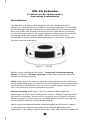
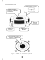
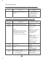
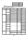
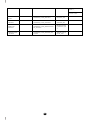
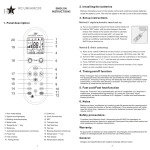
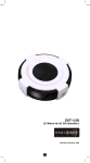
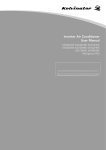
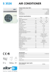
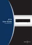
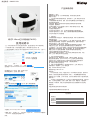
商品编号:6001R-950 产品保修说明 尊敬的客户,您好! 感谢购买我们的产品!为了保障您的权益,请您在使用之前仔细 阅读以下内容: 一. 以下情况不属于免费维修范围,但丰度电气(上海)有限公司可以提 供有偿服务: •未按使用说明书要求安装、使用、维护,或不正确或粗心操作导致的产品 发生故障或造成损坏; •擅自涂改、撕毁产品条形码,或未经授权自行改动固件或拆机修理; •超出保换、报修期限; •因意外因素或人为行为导致的人为损坏,如输入的电压不合适、高温、 进水,机械破坏、摔坏等等; •运输途中导致的损坏; •因不可抗拒力如地震、火灾、水灾雷击等导致的产品故障或损坏; •其他非产品本身设计、技术、制造、质量等问题而导致的故障或损坏。 •其它不可归咎于本公司的原因 欧式Z-Wave红外转换器(ZW2IR) 使用说明书 (注:本中文说明书针对下文列出的系列网关,但也适用其它Z-Wave系列网关) 1、 将电池装入设备,然后将后盖拧上螺丝,再将设备产品合并在一起 2、 添加设备至网关(网关为Z-Wave系列的hub/ihublite/vera/vera2)(图1-1) 图1-2 “Include”为添加设备 “Exclude”为删除设备 图1-1 选择“Include”,点击按钮“ go ”(如图) 出现按钮"Add/Remove:Add new devices now..."( 如图 ) 二. 特别说明: •保修保换仅限于机器主体,外置电源及各类连线、软件产品等附件不在 保修保换范围内。 •在免费包换期间,产品经过丰度电气(上海)有限公司分析,检测,确认故 障是由我司原因导致的,将更换同一型号的返修良品,更换下来的瑕疵 备件归丰度电气(上海)有限公司所有; •在我们的服务机构为您服务时,请您带好相应的发票和产品保修卡;如您 不能出示以上证明,该产品的免费保修期将自其生产日期开始计算。 •经丰度电气(上海)有限公司保换、保修过的产品将享受原始承诺质保的剩 余期限再加3个月的质保期。如产品为付费维修,同一性能问题将享受自 修复之日起3个月止的免费保修期,请索取并保留好您的维修凭证。 •返修产品的邮寄费用由发送方单向负责。 •经销商向您作出的非丰度电气(上海)有限公司保证的其它承诺,丰度 电气(上海)有限公司不承担任何责任。 三. 技术支持和软件升级服务: 在您送修产品之前,请致电我司工程师,以确认产品故障。您也可以 通过登录我们的网站,在www.wintop.com上与技术工程师邮件联系, 寻求技术支持。同时我们会在第一时间内将研发出的各产品驱动程序、 最新版本升级软件发布在我们的网站里,方便您免费下载。 四. 该条例于发布之日起生效。 五. 保修卡内容的最终解释权、修改权归丰度电气(上海)有限公司。 设备制造商:丰度电气(上海)有限公司 网址: www.wintop.com 售后服务电话: 4006 8787 86 按空调控制上的“PROG”按钮。如(图3)所示 成功添加至网关,出现如(图2)所示。 免责声明: 本产品针对指定(特定)产品进行开发,针对不同的产品和型号,具有不同 的功能,使用时须注意功能实现的条件(环境)。未经准确适配和调试所造 成的使用上的一切问题,公司不予负责,但可在付费情况下提供一定的商务支持。 知识产权: 图2 图3 设置参数 点击右上角设置按钮如图 本产品的一切版权等知识产权,以及与"产品"相关的所有信息内容,包括但不 限于:文字表述及其组合、图标、图饰、图表、色彩、界面设计、版面框架、 有关数据、印刷材料、或电子文档等均受著作权法以及其他知识产权法律法 进入如(图4)参数设置界面 规的保护。 可控空调类型及英文说明书请见附件 产品质保前请电话联系我们相关服务人员 产品保修单 您的姓名: 您的电话: 您的地址: 购买时间: 产品问题: 图4 点击按钮“Add configuration settings" 设置如(图4),ID填写“27”,字节选择“1 Byte dec”,Desired Vaule请参考 “Code List”内的各品牌空调的Code。 保存。 可控空调类型及代码 ZW-IR V1.0 Code List Brand(EN) ACURA Aikira Aircon Aircon Aircon Apton AUX AUX AUX BEAVER Carrier Carrier Carrier Carrier Carrier Carrier Carrier Carrier Carrier Carrier Carrier Carrier Carrier Carrier Carrier Carrier Carrier Carrier Chang Hong Chang Hong Chang Hong Chang Hong Chang Hong Chang Hong Chang Hong Chang Hong Chang Hong Chang Hong Chang Hong Chang Hong Chang Hong Chang Hong Chang Hong Chigo Chigo Chigo 8377 Code list 94 174 42 57 58 67 21 189 190 184 88 96 97 98 99 100 101 102 103 104 105 106 107 108 109 110 111 112 5 121 122 123 124 125 126 127 134 135 136 148 178 179 180 42 57 58 Chigo Chuanhua Chuanhua Chunlan Chunlan Chunlan Conrowa Conrowa Conrowa Daewoo Daikin Daikin Daikin Daikin Daikin Daikin Daikin Daikin Daikin Daikin Daikin Daikin Daikin Daikin Fujitsu Fujitsu Fujitsu Fujitsu Fujitsu Fujitsu Fujitsu Fujitsu Fujitsu Fujitsu Fujitsu Fujitsu Fujitsu Fujitsu Fujitsu Fujitsu Fujitsu Galanz Galanz Galanz Galanz General General General General (FUJITSU) Gree 186 37 113 19 150 151 37 70 113 70 1 2 6 11 26 29 30 31 32 33 50 162 163 211 16 25 27 34 158 159 160 161 199 200 201 202 203 204 205 206 227 4 70 83 86 25 27 34 16 15 Gree Gree Gree Gree Gree Guangda Guangda Guangda Haier Haier Haier Haier Haier Haier Haier Haier Haier Haier Haier Haier Haier Hisene Hisene Hisene Hisene Hitachi Hitachi Hitachi Hitachi Hitachi Hitachi Hitachi Hualing Hualing Hualing Huifeng INYCIN Kang Li Kelon Kelon Kelon Kelon Kelvinator Kolin Konka Lennox Lennox Lennox LG LG 18 69 154 155 195 20 37 113 23 75 75 76 76 77 156 172 197 198 207 208 209 9 10 68 80 39 50 51 52 53 120 227 37 56 70 113 70 43 12 13 14 143 87 44 70 69 15 18 17 81 LG LG McQuay Midea Midea Midea Midea Midea Midea Midea Midea_Toshiba Miller Miller Miller Miller Miller Miller Miller Mirage Mirage Mirage MITSUBISHI MITSUBISHI MITSUBISHI Mitsubishi Electric Mitsubishi Electric Mitsubishi Electric Mitsubishi Electric Mitsubishi Electric Mitsubishi Electric Mitsubishi Electric Mitsubishi Electric Mitsubishi Electric Mitsubishi Electric Mitsubishi Electric Mitsubishi Electric Mitsubishi Electric Mitsubishi Electric Mitsubishi Electric Mitsubishi Electric Mitsubishi Electric Mitsubishi Heavy Industries Mitsubishi Heavy Industries Mitsubishi Heavy Industries Mitsubishi Heavy Industries Mitsubishi Heavy Industries Mitsubishi Heavy Industries Mitsubishi Heavy Industries Mitsubishi Heavy Industries Mitsubishi Heavy Industries 82 91 196 40 46 54 55 78 79 113 48 40 42 46 54 55 57 58 15 18 69 194 232 233 228 229 230 231 234 235 236 237 238 239 240 35 37 70 93 153 176 20 36 38 42 42 113 114 115 116 Mitsubishi Heavy Industries Mitsubishi Heavy Industries Mitsubishi Heavy Industries Mitsubishi Heavy Industries Mitsubishi Heavy Industries Mitsubishi Heavy Industries Mitsubishi Heavy Industries Mitsubishi Heavy Industries National NEC NEC NEC NEC NEC NEC NEC NEC NEC NEC NEC NEC NEC NEC NEC NEC NEC NEC NEC NEC NEC Panasonic Panasonic Panasonic Panasonic Panasonic Panasonic Panasonic Panasonic Panasonic Panasonic Panasonic Panasonic Panasonic Panda Philco Samsung Samsung Samsung Samsung Samsung 117 118 119 131 132 133 164 165 211 127 128 129 130 135 136 137 138 139 140 141 142 146 147 148 152 166 167 168 169 170 47 61 62 63 64 65 92 95 183 185 191 241 242 28 41 49 73 74 84 149 Samsung Sanyo Sanyo Sanyo Sanyo Sanyo Sanyo Sanyo Sanyo Sanyo Sanyo Sanyo Sanyo Sanyo Sanyo Sanyo Sanyo Sanyo Sanyo Sanyo Sanyo Sanyo Sanyo Sanyo Sanyo Sanyo Sanyo Sanyo Schneider Electric Shangling SHARP SHARP SHARP SHARP SHARP SHARP SHARP SHARP SHARP SHARP SHARP SHARP SHARP SHARP SHARP SHARP Shinco Shinco SHINING Siemens 171 45 59 60 127 128 129 130 134 135 136 137 138 139 140 141 142 146 147 148 152 166 167 168 169 170 187 218 42 70 7 8 66 90 143 144 145 157 192 193 212 213 214 215 216 217 22 85 70 46 Tadiran TCL TONAL Toshiba Toshiba Toshiba Toshiba Toshiba Toshiba Toshiba Toshiba Toshiba Toshiba Toshiba Toshiba Toshiba Trane Trane Trane VOLTAS Xileng YORK YORK Yutu 54 24 188 71 175 177 181 182 219 220 221 222 223 224 225 226 3 173 174 4 150 15 89 70 English version Z:-,5 (Z-Wave-to-AC IR Extender) Firmware Version: V1.0 1 Table of Contents Introduction .................................................... 3 Controller and Gateway Requirements ............ 4 Built-in IR code library .................................... 4 Glossary .......................................................... 5 Z:-,5 Operations ........................................ 6 Product Overview ............................................. 7 Z-Wave Remote Control ................................... 8 Z:-,5 Information ....................................... 9 Listening Mode Change .................................... 11 IR Code Selection ............................................ 11 IR Code Learning ............................................ 13 Reset Z:-,5 to factory default........................ 17 INSTALLATION ................................................ 18 MOUNTING THE Z:-,5 TO A WALL .................. 18 WIRELESS INFORMATION ............................... 21 MAINTENANCE................................................. 21 FREQUENTLY ASKED QUESTIONS .................... 21 Z-Wave Frequently Asked Questions ................... 21 TECHNICAL SPECIFICATIONS .......................... 23 CHECKING ACCESSORIES ................................ 28 FCC NOTICE .................................................... 28 WARNINGS ...................................................... 28 CAUTION ........................................................ 28 2 Z:-,5([WHQGHU (Z-Wave-to-AC IR Extender) Operating Instructions Introduction The ZW‐IR is a Z‐Wave to IR extender for air‐conditioner (AC), (Figure 1), it works with any Z‐Wave compliant gateway or controller by translating Z‐Wave Thermostat Commands to AC IR control code. User can select the IR code from the built‐in code library of ZW‐IR, or use learning function, by using Z‐Wave Configuration Commands according to the parameter table. ZW‐IR is also with built-in temperature sensor which allows gateway or controller to get the current room temperature. Figure 1 Z:-,5 ZW‐IR can be configured as either “Frequently Listening Routing Slaves” (FLiRS) or “Always Listening” node after exclusion process (before inclusion process). FLiRS node type is for battery operated applications and it will enter sleep mode frequently in order to conserve battery consumption that can provide the flexibility if there is out of 5Vdc power source. Also, user can place the unit in anywhere at home. Always Listening node type is for the needs of fast response application. It works with 5Vdc power source. Always Listening node can act as a repeater, which will re‐transmit the RF signal to ensure that the signal is received by its intended destination by routing the signal around obstacle and radio dead spots. ZW‐IR supports Network Wide Inclusion (NWI) and Explore Frames. It also supports Z‐Wave networks with multiple gateways and controllers. Like every Z‐Wave accessory, user will need to include the 3 ZW‐IR into their Z‐Wave network using the primary controller. Then, the user can use either the primary controller or secondary controller to configure and setup the ZW‐IR using Z‐Wave’s configuration command class. Once the configuration and setup is complete, the controller can use Z‐Wave “Thermostat commands class” to control their IR‐controlled air‐conditioner through the ZW‐IR. Controller and Gateway Requirements The ZW‐IR can work with any Z‐Wave compliant controller or gateway supporting the following Z‐Wave commands. - Configuration Command Class - Multilevel Sensor Command Class - Thermostat Command Class Thermostat Mode Command Class Thermostat Fan Mode Command Class Thermostat Set‐point Command Class Built‐in IR code library The Built‐in IR code library supports most of the popular air conditioner brands in the market. Z‐Wave gateway and controller does not need to have any IR control code knowledge. User can use Z‐ Wave controller or gateway to select the IR code according to the ZW‐IR code list separately provided through Z‐Wave configuration command. 4 Glossary Device or Node Inclusion Exclusion Remove Z‐Wave Network Primary Controller Secondary Controller Inclusion Controller Devices and nodes are all terms to describe an individual Z‐Wave device. These are all interchangeable when setting up your Z‐Wave network. Add a Z‐Wave device to the network. Delete a Z‐Wave device from the network. To take a device out of a group, scene or association group while that device still exists in the same Z‐Wave network. A collection of Z‐Wave devices is controlled by primary and secondary controllers operating on the same system. A Z‐Wave network has its own unique ID code so that controllers not in the network cannot control the system. The first controller is used to set up your devices and network. Only the Primary Controller can be used to include or delete devices from a network. It is recommended that you mark the primary controller for each network for ease in modifying your network. A controller containing network information about other devices within the network and is used for controlling devices. Secondary controller is created from the Primary Controller and cannot include or delete devices to the network. A controller containing network information about other devices within the network and is used for controlling devices. Inclusion controller is created from the Primary Controller in a SIS enabled Z‐Wave network. Inclusion Controllers have the ability to add and remove devices from the network. 5 ZW‐IR Operations Before using the ZW‐IR, please read the [INSTALLATION] if you need to mount the ZW-IR to a wall. Power up the ZW-IR by the USB Power 5Vdc or Dry battery AAA x 3pcs. • Plug‐in 5Vdc power into the USB socket if operated at Always Listening mode. Or • Install 3xAAA batteries if operated at FLiRS mode. • Please refer to the section of [MOUNTING PROCEDURE]. • Remove the battery cover on the back of your ZW-IR battery chassis. • Mount the battery cover into the main unit with 2 screws. • Check the polarity of the batteries and the "+/‐" marks inside the battery compartment. • Insert the batteries. • Push the battery cover and main unit back in place. L CAUTION (battery and power adaptor safety) − Use new batteries of the recommended type and size only. − Never mix used and new batteries together. − To avoid chemical leaks, remove batteries from the ZW-IR if you do not intend to use the remote for an extended period of time. − Dispose of used batteries properly; do not burn or bury them. (Please carefully read through the following then store the manual for future reference.) 6 Product Overview Temperature sensor “PROG” Button, Learning and LED Indication Battery chassis External IR Port USB Power 5V DC Surround IR Output for top and 4-directions Figure 2 PROG Key and IR Port of Z:,5 7 Z‐Wave Remote Control 1) 2) 3) 4) 5) Select your operation mode; please refer to “Listening Mode” section. Include or Exclude the unit from the existing Z‐Wave home control network with your primary controller. ‐ Refer to your primary controller instructions to process the inclusion / exclusion setup procedure. ‐ When prompted by your primary controller, click once on the PROG button. ‐ The primary controller should indicate that the action was successful. If the controller indicates the action was unsuccessful, please repeat the procedure. User can use either primary controller or secondary controller (should support configuration command class) to setup the ZW‐IR AC code by the parameter 27 (IR code number for built‐in code library), please refer to code list for the parameter value then setup your AC control code. Once the configuration and setup were completed, the controller can use Z‐Wave “Thermostat commands class” to control their IR‐controlled air‐conditioner with the ZW-IR. You can record down your device code under the below table for future reference after setting up the ZW-IR correctly. AC device programmed to your ZtͲ/Z Code no.: 8 ZtͲ/Z Information How to get the NIF “Node Information Frame” on ZW-IR (Inclusion) Step 1 Setup Key LED Indication Status on ZW-IR Press the PROG button on the ZW-IR • LED flashes once then stay off (ZW-IR will report the supported command class) Parameter No. and Parameter Value of configuration command Parameter Definitions Parameter Value Number 25 Indicate a location for IR code 0‐22 (0x19) learning and start learning (0x00 – 0x16) 26 Learning status register 0x00: Idle ‐ this IR (0x1A) channel is idle (default) Note: 0x01: OK ‐ the latest The status value 0x01 and learning process 0x04 will be reset to 0 when successful and the ZW-IR receive a get completed command to this parameter 0x02: Learning ‐ the ZW-IR is busy processing previous learning request 0x04: Failed ‐ the latest learning request failed 27 IR code number for built‐in Refer “Code list” for (0x1B) code library details 28 (0x1C) External IR Emitter power level 32 (0x20) Surround IR control - to avoid the IR interference by disabling the surrounding IR emitter if 2 9 0x00: normal power mode 0xFF: high power mode (default) 0x00: disable Surround IR Emitters 0xFF: enable Surround IR Emitters air‐conditioners in a room are used - extend the battery life by disabling the Surround IR Emitters AC function “SWING” control 33 (0x21) 35 (0x23) Learn location status (default) 0x00: SWING OFF 0x01: SWING AUTO (Default) Bit mask = 1, learn location has learn data. Otherwise, Bit mask = 0 See figure “Learn location” as below Parameter Table 7 6 5 4 3 2 1 0 1 0 0 0 0 0 1 0 7 6 5 4 3 2 1 0 0 0 0 1 0 0 0 1 7 6 5 4 3 2 1 0 0 0 0 0 0 0 0 1 7 6 5 4 3 2 1 0 0 0 0 0 0 0 0 0 Bit Mask Byte 1 Location 0‐7 Bit Mask Byte 2 Location 8‐15 Bit Mask Byte 3 Location 16‐23 Bit Mask Byte 4 [Reseved] Figure: Learn location On the above example, location 1, 7, 8, 12, 16 has learned data. L Mapping Information − − BASIC Set Value 0x00 will map to Thermostat mode Off 0x00. BASIC set Value 0xFF will map to Thermostat mode Resume 0x05. 10 Listening Mode Change (default mode is FLiRS) ZW-IR can be configured as either “FreqƵentlLJ ListeŶing Routing Slaves” (FLiRS) or “Always Listening” node after exclusion process. FLiRS node type is targeted for battery operated applications and it will enter sleep mode frequently in order to conserve battery consumption. Always Listening node type is targeted for the needs of required a fast response application. Important: It is not allowed to changing ZtͲ/Z opeƌatŝoŶ moĚewithout exclusion process (do not change ZtͲ/Z operation mode whilet‐/Z is included in a neƚwŽrk). How to switch ZW-IR listening mode from“Always Listening “FLiRS" (or vice verse) " to LED Indication Status on ZW-IR Step Setup Key 1 Press and hold the PROG button on the ZW-IR for around 4 seconds • LED stay off Release the button and then press the PROG button 3 times within 2 seconds • LED flashes twice then stay off 2 (ZW-IR set in FLiRS mode) OR • LED flashes four times then stay off (ZW-IR set in Always Listening mode) IR Code Selection ZW-IR is with built-in IR AC code library, user may select the IR code using Configuration Command Class. Step LED Indication Status on ZW-IR Setup Key 11 ‐ 1 After included ZW-IR to Z‐Wave controller or Gateway, go to device setup for configuration on gateway or controller. ‐ 2 Input parameter number “27” and parameter value (please look up the code list of ZW-IR according to your AC brand). Then complete the configuration process. 3 Press the PROG button on the ZW-IR. (this step apply when using portable controller for set up, if using gateway, user can skip this step) • LED flashes once when ZW-IR receives the configuration setting Go back to the control page of ZW-IR on the gateway and try the function such as (cool, temperature set). • LED flashes once every time it receives a command from gateway 4 If the air conditioner does not respond to the command you set on Gateway (Cool, Heat, Auto, Temperature set etc.), repeat step 2 and 3 to select the next code on code list. L Important Information − Different brand or model of air conditioner has different function. For example, some air conditioner only support o o o temperature set from 18 C‐30 C, if user set 17 C on gateway, ZW-IR will not respond. − There are more than 1 code for each brand, some does not support heat, if user selected a code that does not support heat but the original air conditioner supports heat function, please continue to try next code until the correct one is selected. − If none of the code works on the target air conditioner, or the air conditioner brand is not shown on the code list, please select code “000” for IR code learning (refer to instruction of IR Code Learning) 12 IR Code Learning In case none of the code on the code list works for the targeted air conditioner, user can use IR code learning function using configuration according to below steps: LED Indication Status on ZW-IR Step Setup Key 1 Go to configuration setting page on the gateway or ZW-IR and input parameter number “27” and parameter value “000” to select the dedicated AC code number “000” for learning. • LED flashes once when ZW-IR receives the configuration setting Look up below mapping table (value 0‐22) for learning, and decide the IR setting you intent to learn next. 2 3 4 ‐ For example “22°C, cool” which matches value “5” (IR code to be learnt will locate at “5” in ZW-IR). Set your original air conditioner remote at “22°C, cool” and turn it off. (Besides temperature and mode, you may set other desired settings, such as Fan, Swing etc.) Go to configuration setting page on the gateway and input parameter number “25” and parameter value “5” (in this case). Press the PROG button on the ZW-IR. (this step apply when using portable controller for set up, if using gateway, user can skip this step) ‐ • LED flashes once when ZW-IR receives the configuration setting • ZW-IR is ready to learn 5 Aim the original air conditioner remote at ZW-IR according to below position within 1‐3 inches LED flashes twice if learning is successful. LED flashes 6 times if it’s failed. 13 Press “power on” button on the original air conditioner remote. If the learning is failed, repeat step 3 to step 5. To learn next IR code, repeat step 2 to step 5. L When you encounter problem, check followings: − Make sure your original remote is switched to power off. − Press the key on original remote before learning mode timeout. − Keep away from incandescent light and direct sunlight during learning. − Make sure IR Transmitter of your original remote alight with learning diode of ZW-IR, you may also slight adjust closer or further away the distance of two devices. Some of remotes the IR transmitter in hidden behind lens and may not installed center of remote. − Make sure the power is good on both devices, especially the original remote. Use fresh batteries. 14 IR Learning Mapping Table (Parameter number 25) Parameter Value Thermostat command (Location) & IR setting 0 OFF 1 ON (resume) 2 19°C cool 3 20°C cool 4 21°C cool 5 22°C cool 6 23°C cool 7 24°C cool 8 25°C cool 9 26°C cool Default Cool 10 27°C cool 11 28°C cool 12 19°C heat 13 20°C heat 14 21°C heat 15 22°C heat Default Heat 16 23°C heat 17 24°C heat 18 25° C heat 19 26°C heat 20 27°C heat 21 28°C heat 22 Dry mode 15 L Important Information After all learning completed, user can go back to the ZW-IR control page on the gateway for normal operation. − On the gateway UI, user can only use the temperature range from the mapping table, OFF, ON(RESUME), COOL, HEAT, DRY, If user press the button of FAN, or other function on the gateway UI which is not listed in above table, ZW-IR will not respond. − If user only learnt ON, OFF, or part of the settings according to the above table, ZW-IR will send the learnt data to the air conditioner only. For example, user only learnt ON, OFF, 22°C Cool, 24°C Heat, ZW-IR will not send IR data to air conditioner if user set 27°C Cool on the gateway. − ZW-IR has been pre‐defined default cool at 26°C, default heat at 22°C, when user press Cool on gateway without setting temperature, ZW-IR will send the learnt data of 26°C Cool to air conditioner. When user press Heat on gateway without setting temperature, ZW-IR will send the learnt data of 22°C Heat to air conditioner. − There is only one code for dry mode, user can set it at any preferred temperature. − User can still use gateway to set up scene and schedule with ZW-IR, for example, to have AC turn on at 23°C every day at 7pm, 25°C at 11pm. Just make sure the set code is learnt. − The learning mapping table is for split air conditioner which remote control is with LCD display. For window type air conditioner (which remote control is without LCD display), the mapping table with temperatures do not apply, due to different type of IR control protocol. However, user may still use the OFF, or ON/RESUME, DRY key for learning. (Because the POWER key on the original remote without LCD display is toggle, user can choose either ON key, or OFF key to learn Power key, after learning is done, press once to turn on the air conditioner if the air conditioner is OFF, press once to turn off if the air conditioner is ON) 16 Reset ZtͲ/Z tofactorydefault Press and hold “PROG” button for 10seconds on ZW-IR. The LED will flash twice until reset process is completed. Note: This reset step will not affect the operation mode of ZtͲ/Z, user should refer to “Listening Mode" section if you want to change the operation mode. L Information − If you are using Gateway or other Z‐wave controllers to operate ZW-IR, Please follow the instruction from the gateway or other controller. − You can check the specifications in the manual of your ZW-IR. 17 INSTALLATION MOUNTING THE ZW-IR TO A WALL MOUNTING LOCATION PRECAUTIONS • Before mounting, check the material and structure of the mounting location. If the location does not have the proper material or structure, the ZW-IR can fall and cause injuries. • Use commercial items that best match the wall structure and material for the screws and other fixtures. • Do not mount near a kitchen counter, humidifier, or other location in which it can be exposed to smoke or steam. Doing so could cause a fire or electrical shock. • Do not mount in locations with high humidity or large amounts of dust. Doing so could cause a fire or electrical shock. • Do not mount to locations subject to high temperatures, high humidity, or exposure to water. Doing so could cause a fire or electrical shock. • Do not mount to locations subject to large amounts of vibration, large jolts, or large forces. These could cause an injury if the ZW-IR falls and breaks. MOUNTING PROCEDURE PRECAUTIONS • Do not modify parts or use the ZW-IR in ways other than its intended use. Doing so could cause the ZW-IR to fall and result in an injury. • Be sure to fully check that there are no electrical wires or pipes inside the wall before mounting. • If any of the screws are loose, the ZW-IR can fall and cause an injury. Do not mount the ZW-IR with the screws still loose. • Check that the two screws mounted to the wall are fully inserted into the key holes of the ZW-IR. Otherwise, the ZW-IR can fall and cause an injury. • Do not mount the ZW-IR so that it sticks out from the wall edge. It could get hit by people’s bodies or objects and cause an injury. • Supplier will not be liable for any accidents or injuries that occur due to improper mounting or handling. • When mounting, be careful not to get your fingers pinched or injure your hands. MOUNTING PROCEDURE The ZW-IR can be mounted to a wall or wooden racks using the two key holes in the bottom case. Note 1: The reception sensitivity varies depending on the antenna direction. 18 Note 2: Before mounting to a wall, be sure to fully read the precautions. 1. Obtain two screws suitable for the wall strength and material. The screw size is shown in the figure below. 2. The positional relationship between the ZW-IR key holes and the screw mounting positions are shown in the figure below. Note 1: When mounting the screws to the wall, leave a space between the wall and screw cap as shown in the figure. 3. 4. Insert the ZW-IR key holes onto the two screws mounted to the wall, and then slide downward to secure in place. After securing the ZW-IR to the wall, connect the USB Power or batteries and IR emitter cable to the ZW-IR. 19 Note 1: Check that the Z:,5 is firmly secured to the wall. Note 2: Insert USB plug or batteries and IR emitter cable so that they are firmly connected to the Z:,5. 5. 6. When removing the ZW-IR from the wall, lift up the ZW-IR, then pull it towards you. Detach the main unit from the battery chassis by move toward to top position. 20 WIRELESS INFORMATION Wireless range: This device has an open‐air line‐of‐sight transmission distance of 100 feet which complies with the Z‐Wave standards. Performance can vary depending on the amount of objects in between Z‐Wave devices such as walls and furniture. Every Z‐Wave device set up in your network will act as a signal repeater allowing devices to talk to each other and find alternate routes in the case of a reception dead spot. Radio frequency limitations: 1. Each wall or object (i.e.: refrigerator, bookshelf, large TV, etc) can reduce the maximum range of 65 feet by up to 25 to 30%. 2. Plasterboard and wooden walls block less of the radio signal then concrete, brick or tile walls which will have more of an effect on signal strength. 3. Wall mounted Z‐Wave devices will also suffer a loss of range if they are housed in metal junction boxes which could also reduce the range by up to 25 to 30%. MAINTENANCE 1 2 3 4 5 Do not expose your ZW-IR to dust, strong sunlight, humidity, high temperatures or mechanical shocks. Do not use old and new batteries together as old batteries tend to leak. Do not use corrosive or abrasive cleansers on your ZW-IR. Keep the unit dust free by wiping it with a soft, dry cloth. Do not disassemble your ZW-IR, it contains no user‐serviceable parts. FREQUENTLY ASKED QUESTIONS Z‐Wave Frequently Asked Questions Q Why won’t my ZtͲ/Z workwith the ZͲWave deviĐeƐ I purchased from another country? A Due to different countries regulations Z‐Wave products from different regions are set to different frequencies. Before purchasing new devices make sure you have checked that the device is compatible in your region. Q How do I know which product is compatible with my ZtͲ/Z? A ZW-IR should work with any Z‐Wave controller or gateway that has control capability for “Thermostat” devices. You can check either the specifications in the manual of your ZW-IR. 21 Q Can I use the USB port to configure ZtͲ/Z? A No, the mini USB port only provides an alternative option for user to power the ZW-IR. Q Do I need an electrician to install Z‐Wave products in my house? A Installation can be simple. In some cases all you need to do is You also can place mount the ZW-IR to a wall or wooden racks. the ZW-IR on the desk and power it with dry cell batteries. Q How to select my air‐conditioner IR code from ZtͲ/Z? A You should refer to the code list and look into the brand and try the code no. sequentially until you find the right code. You can record down your device code under the table for future reference after setting up the ZW-IR correctly. Q ZtͲ/Z is workiŶg on top and 4‐diƌeĐtŝoŶsIRoutput, but theƌe is no response on the IR emitter socket, why? A ZW-IR supports two IR power levels for the external IR emitter to avoid saturation of the IR receiver. You can set the IR output power level by the Parameter Table value (normal or high power mode) or adjust the position of your external IR emitter. What is the max. units Q Can I use 2 or more ZtͲ/Z inmyhouse? if yes? A Yes and it is very depend on the capability of gateway / controller. For example, gateway can supports up to 8, 16 or 32 ZW-IR in a network. Q How to avoid the IR interference if I am using 2 identical air‐ conditioners in same location but want to control them individually? A User can disable the Surround IR Output function, connect the external IR emitter and aim it at the specific AC unit. The operating distance of external IR emitter is around 100cm (High power mode) and 50cm (Low power mode) but it is also depends on the sensitivity of the IR receiver. External IR emitter cable 22 Q Where can I keep up to date with the latest Z‐Wave products for my house? A You can keep up to date by visiting the www.wintop.com website where we will have information and ideas for using Z‐ Wave technology. TECHNICAL SPECIFICATIONS Model no. RF frequency RF operating distance (ZW-IR EU) (ZW-IR AU) (ZW-IR US) (ZW-IR IN) 868.4MHz (EU) 921.4MHz (AU) 908.4MHz (US) 865.22MHz (IN) up to 80ft outdoor line of sight, in unobstructed environment IR operating distance up to 25ft line of sight, in unobstructed environment IR learning Max. 23 commands Temperature Powered by Dimension Weight Measurable range: 32 – 104 °F / 0 – 40 °C Operation: 0 ‐ 40°C Storage: ‐20 ‐ 60°C USB Power DC 5V 100mA or Dry battery AAA x 3pcs Dia.=70mm, T = 18mm (Main unit) Dia.=70mm, T = 15.5mm (Battery chassis) 35g (Battery chassis excluded) 60g (Battery chassis included) 90g (Main + Battery chassis + AAA x3pcs) Z‐Wave device type Basic Device Class: BASIC_TYPE_ROUTING_SLAVE Generic Device Class: GENERIC_TYPE_THERMOSTAT Specific Device Class: SPECIFIC_TYPE_THERMOSTAT_GENERAL_V2 Z‐Wave Command Class Version Controlled Supported COMMAND_CLASS_THERMOSTAT_MODE Version2 NO YES COMMAND_CLASS_THERMOSTAT_SETPOINT Version2 NO YES COMMAND_CLASS_THERMOSTAT_FAN_MODE Version2 NO YES COMMAND_CLASS_BATTERY Version1 NO YES 23 COMMAND_CLASS_CONFIGURATION Version1 NO YES COMMAND_CLASS_BASIC Version1 NO YES COMMAND_CLASS_VERSION Version1 NO YES COMMAND_CLASS_SENSOR_MULTILEVEL Version1 NO YES COMMAND_CLASS_SWITCH_ALL Version1 NO YES COMMAND_CLASS_MANUFACTURER_SPECIFIC Version1 NO YES Supported function in Thermostat Command Class Z‐Wave command class Description Supported Auto/Auto Low YES Low YES Auto High YES High YES Auto Medium YES Medium YES Heating YES Cooling YES Furnace NO Dry Air YES Thermostat Fan mode Thermostat Set point Thermostat Mode Moist Air NO Auto changeover YES Energy Save heating NO Energy Save cooling NO Away heating NO Off YES Heat YES Cool YES Auto YES Auxiliary/Emergency Heat NO Resume YES Fan only YES Furnace NO Dry Air YES Moist Air NO 24 Auto Changeover YES Energy Save Heat NO Energy Save Cool NO AWAY NO ZW-IR functions and Parameters summaries: AIR FUNCTIONS CONDITIONER Z-WAVE COMMAND COMMAND PARAMETER Z-WAVE COMMAND CLASS FUNCTION COMMAND_CLASS_THERMOSTAT THERMOSTAT_ _MODE MODE_SET COMMAND_CLASS_BASIC BASIC_SET COMMAND_CLASS_THERMOSTAT THERMOSTAT_ _MODE MODE_SET COMMAND_CLASS_BASIC BASIC_SET COMMAND_CLASS_THERMOSTAT THERMOSTAT_ _MODE MODE_SET COMMAND_CLASS_THERMOSTAT THERMOSTAT_ _MODE MODE_SET COMMAND_CLASS_THERMOSTAT THERMOSTAT_ _MODE MODE_SET COMMAND_CLASS_THERMOSTAT THERMOSTAT_ _MODE MODE_SET COMMAND_CLASS_THERMOSTAT THERMOSTAT_ MODE = 5 POWER ON VALUE = 0XFF POWER MODE = 0 POWER OFF AUTO VALUE = 0X00 MODE = 3 COOL MODE = 2 FAN MODE = 6 MODE HEAT MODE = 1 DRY MODE = 8 _MODE MODE_SET AUTO COMMAND_CLASS_THERMOSTAT THERMOSTAT_ Changeover _MODE MODE_SET MODE = 10 SETPOINT TYPE = HEAT mode 1, Temperature TEMPERATURE VALUE SETPOINT TYPE = COOL mode 2, Temperature TEMPERATURE TEMPERATURE COMMAND_CLASS_THERMOSTAT THERMOSTAT_ VALUE SETTING _SETPOINT SETPOINT_SET SETPOINT TYPE = DRY mode 8, Temperature TEMPERATURE VALUE SETPOINT TYPE = AUTO mode 10, Temperature TEMPERATURE VALUE THERMOSTAT_ COMMAND_CLASS_THERMOSTAT FAN SPEED FAN_MODE_SE FAN MODE = 0 _FAN_MODE, v1 T FAN AUTO THERMOSTAT_ COMMAND_CLASS_THERMOSTAT FAN MODE = 0, 2, or FAN_MODE_SE _FAN_MODE, v2 4 T 25 THERMOSTAT_ COMMAND_CLASS_THERMOSTAT FAN_MODE_SE FAN MODE = 1 _FAN_MODE, v1 T FAN LOW (1/3) THERMOSTAT_ COMMAND_CLASS_THERMOSTAT FAN_MODE_SE FAN MODE = 1 _FAN_MODE, v2 T FAN MID (2/3) - - THERMOSTAT_ COMMAND_CLASS_THERMOSTAT FAN_MODE_SE FAN MODE = 5 _FAN_MODE, v2 T THERMOSTAT_ COMMAND_CLASS_THERMOSTAT FAN_MODE_SE FAN MODE = 3 _FAN_MODE, v1 T FAN HIGH (3/3) THERMOSTAT_ COMMAND_CLASS_THERMOSTAT FAN_MODE_SE FAN MODE = 3 _FAN_MODE, v2 T PARAMETER NO. = 33 SWING ON/ COMMAND_CLASS_CONFIGURATI CONFIGURATIO SWING AUTO ON N_SET SIZE = 1 VALUE = 1 SWING PARAMETER NO. = 33 COMMAND_CLASS_CONFIGURATI CONFIGURATIO ON N_SET SIZE = 1, SWING OFF VALUE = 0 PARAMETER NO. = 27 COMMAND_CLASS_CONFIGURATI CONFIGURATIO ON N_SET SIZE = 2, IR CODE SETUP VALUE = (CODE#) PARAMETER NO. = 28 NORMAL COMMAND_CLASS_CONFIGURATI CONFIGURATIO POWER LEVEL ON N_SET SIZE = 1, VALUE = 0 IR TRANSMISSION PARAMETER NO. = POWER LEVEL 28 HIGH POWER COMMAND_CLASS_CONFIGURATI CONFIGURATIO LEVEL ON N_SET SIZE = 1, VALUE = 0xFF FRONT IR PARAMETER NO. = TRANSMISSION 32 CONTROL COMMAND_CLASS_CONFIGURATI CONFIGURATIO ON N_SET COMMAND_CLASS_CONFIGURATI CONFIGURATIO PARAMETER NO. = ON N_SET 32 SIZE = 1, DISABLE VALUE = 0 ENABLE 26 SIZE = 1, VALUE = 0xFF BATTERY COMMAND_CLASS_BATTERY BATTERY_GET VERSION COMMAND_CLASS_VERSION VERSION_GET MANUF'ER COMMAND_CLASS_MANUFACTUR SPECIFIC ER_SPECIFIC LEVEL MANUFACTURE R_SPECIFIC_GE T TEMPERATURE SENSOR COMMAND_CLASS_SENSOR_MUL SENSOR_MULTI TILEVEL LEVEL_GET 27 CHECKING ACCESSORIES After opening the cover of the packing box, check that the following accessories are included. • ZW-IR (Z-Wave‐to‐AC IR Extender) • Screws (bottom cover) x 2pcs • ZW-IR User Manual (download from our website) • AC Code List (download from our website) FCC NOTICE This device complies with Part 15 of the FCC rules. Operation is subject to the following two conditions: (1) this device may not cause harmful interference, and (2) this device must accept any interference received, including interference that may cause undesired operation. WARNINGS Changes or modifications not expressly approved by the party responsible for compliance could void the user's authority to operate the equipment. ‐ RISK OF FIRE ‐ RISK OF ELECTRICAL SHOCK ‐ RISK OF BURNS ‐ The socket‐outlet shall be installed near the equipment and shall be easily accessible. ‐ Use only power supplies listed in the user instructions. Do not dispose of electrical appliances as unsorted municipal waste, use separate collection facilities. Contact your local government for information regarding the collection systems available. CAUTION ‐ RISK OF EXPLOSION IF BATTERY IS REPLACED BY AN INCORRECT TYPE. ‐ DISPOSE OF USED BATTERIES ACCORDING TO THE INSTRUCTIONS. www.wintop.com 28