1
Point-to-point Link CP 441 Installation ___________________
Preface
and Parameter Assignment SIMATIC
S7-400
Point-to-point Link CP 441
Installation and Parameter
Assignment
Manual
1
___________________
Product Description
Basic Principles of Serial
2
___________________
Data Transmission
3
___________________
Commissioning the CP 441
4
___________________
Mounting the CP 441
Configuring and Assigning
5
___________________
Parameters for the CP 441
Communication via System
6
___________________
Function Blocks
Start-up Characteristics and
Operating Mode Transitions
of the CP 441
7
___________
Diagnostics Functions of the
8
___________________
CP 441
Programming Example for
9
___________________
System Function Blocks
A
___________________
Technical Specifications
B
___________________
Cables
C
___________________
SFB Parameters
Accessories and Order
D
___________________
Numbers
E
___________________
Literature on SIMATIC S7
04/2012
A5E00405449-03
Legal information
Legal information
Warning notice system
This manual contains notices you have to observe in order to ensure your personal safety, as well as to prevent
damage to property. The notices referring to your personal safety are highlighted in the manual by a safety alert
symbol, notices referring only to property damage have no safety alert symbol. These notices shown below are
graded according to the degree of danger.
DANGER
indicates that death or severe personal injury will result if proper precautions are not taken.
WARNING
indicates that death or severe personal injury may result if proper precautions are not taken.
CAUTION
with a safety alert symbol, indicates that minor personal injury can result if proper precautions are not taken.
CAUTION
without a safety alert symbol, indicates that property damage can result if proper precautions are not taken.
NOTICE
indicates that an unintended result or situation can occur if the relevant information is not taken into account.
If more than one degree of danger is present, the warning notice representing the highest degree of danger will
be used. A notice warning of injury to persons with a safety alert symbol may also include a warning relating to
property damage.
Qualified Personnel
The product/system described in this documentation may be operated only by personnel qualified for the specific
task in accordance with the relevant documentation, in particular its warning notices and safety instructions.
Qualified personnel are those who, based on their training and experience, are capable of identifying risks and
avoiding potential hazards when working with these products/systems.
Proper use of Siemens products
Note the following:
WARNING
Siemens products may only be used for the applications described in the catalog and in the relevant technical
documentation. If products and components from other manufacturers are used, these must be recommended
or approved by Siemens. Proper transport, storage, installation, assembly, commissioning, operation and
maintenance are required to ensure that the products operate safely and without any problems. The permissible
ambient conditions must be complied with. The information in the relevant documentation must be observed.
Trademarks
All names identified by ® are registered trademarks of Siemens AG. The remaining trademarks in this publication
may be trademarks whose use by third parties for their own purposes could violate the rights of the owner.
Disclaimer of Liability
We have reviewed the contents of this publication to ensure consistency with the hardware and software
described. Since variance cannot be precluded entirely, we cannot guarantee full consistency. However, the
information in this publication is reviewed regularly and any necessary corrections are included in subsequent
editions.
Siemens AG
Industry Sector
Postfach 48 48
90026 NÜRNBERG
GERMANY
A5E00405449-03
Ⓟ 05/2012 Technical data subject to change
Copyright © Siemens AG 2012.
All rights reserved
Preface
Purpose of This Manual
This manual explains how to establish and operate a point-to-point link.
Contents of the manual
The manual describes the hardware and software of the CP 441 communication processor
and its integration in an S7-400 automation system.
The following subjects are covered:
● The basics of point-to-point link with the CP 441
● Commissioning the CP 441
● Mounting the CP 441
● Communication via the CP 441
● Troubleshooting
● Application examples
● Properties and technical specifications
Scope of the manual
The manual is relevant to the following CPs and interface modules:
Product
Order number
As of Release
CP 441-1
6ES7 441-1AA04-0AE0
6ES7 441-1AA05-0AE0
01
01
CP 441-2
6ES7 441-2AA04-0AE0
6ES7 441-2AA05-0AE0
01
01
RS232 module
6ES7 963-1AA00-0AA0
6ES7 963-1AA10-0AA0
01
01
20 mA TTY module
6ES7 963-2AA00-0AA0
6ES7 963-2AA10-0AA0
01
01
X27 (RS422/485) module
6ES7 963-3AA00-0AA0
6ES7 963-3AA10-0AA0
01
01
Point-to-point Link CP 441 Installation and Parameter Assignment
Manual, 04/2012, A5E00405449-03
3
Preface
NOTICE
For CP 441 up to order number 6ES7 441-xAA04-0AE0, IF 963 interface modules with
order number 6ES7 963-xAA00-0AA0 are used.
For CP 441 as of order number 6ES7 441-xAA05-0AE0, the IF 963 interface modules with
order number 6ES7 963-xAA10-0AA0 must be used.
Note
The descriptions of the CP 441 communication processor and the interface modules in this
manual were correct at the time of publication. We reserve the right to describe modifications
to the functionality of the modules in a separate Product Information.
Changes compared to the previous version (04/2011)
Compared to edition 04/2011 of this manual, this edition describes the additional functions of
the CP 441 (as of order number 6ES7441-xAA05-AE0; x=1,2).
This includes:
● Firmware update via HW Config
● Identification data (I&M functions)
● Elimination of limitations (depending on the type of interface) for the data transmission
rate
– CP441-1: Additional data transmission rates 57.6, 76.8 and 115.2 kbps
– CP441-2: Both interfaces can be operated with 115.2 kbps
● Lowest character delay time at 9600 bps: 2 ms
● Lowest character delay time at data transmission rates ≥ 19.2 kbps: 1 ms
● The dependency of the waiting times on the data transmission rate can be set with
RK512.
Approvals
You can find detailed information about certificates, approvals and standards in the manual
S7-400 Programmable Controller; Module Specifications.
Point-to-point Link CP 441 Installation and Parameter Assignment
4
Manual, 04/2012, A5E00405449-03
Preface
Structure of This Manual
To help you to quickly find the information you require, this manual offers the following:
● A heading indicating the contents of each section is provided in the left-hand column on
each page of each chapter.
● Following the appendices, a glossary defines important technical terms used in the
manual.
● Finally, a comprehensive index allows quick access to information on specific subjects.
Additional assistance
Please contact your local Siemens representative if you have any queries about the products
described in this manual.
● Find your contact partner at:
http://www.siemens.de/automation/partner (http://www.siemens.com/automation/partner)
● You can find the guide to the technical documentation for the individual SIMATIC
products and systems at:
http://www.siemens.de/simatic-doku (http://www.siemens.com/simatic-doku)
● The online catalog and the online ordering system are available at:
http://www.siemens.de/automation/mall (http://www.siemens.com/automation/mall)
Conventions
This manual uses the generic term CP 441. This information in the manual apples to the
CP 441-1 and CP 441-2 communication processors, unless otherwise specified.
Training Center
We offer a range of courses to help get you started with the S7 automation system. Please
contact your local training center or the central training center in Nuremberg, D90327 Germany.
Internet: http://www.siemens.com/sitrain (http://www.siemens.com/sitrain)
Point-to-point Link CP 441 Installation and Parameter Assignment
Manual, 04/2012, A5E00405449-03
5
Preface
Technical support
You can reach the technical support for all A&D products
● Use the Web form for the support request
http://www.siemens.com/automation/support-request
(http://www.siemens.com/automation/support-request)
Additional information about Siemens Technical Support is available on the Internet at
http://www.siemens.de/automation/service&support
(http://www.siemens.com/automation/service&support)
Service & Support on the Internet
In addition to our documentation, we offer a comprehensive knowledge base online on the
Internet.
http://www.siemens.de/automation/service&support
(http://www.siemens.com/automation/service&support)
There you will find:
● The newsletter, which provides the latest information on your products.
● The documents you require, using our Service & Support search engine.
● A forum where users and specialists exchange information worldwide.
● Your local service partner for Automation & Drives in our contact database.
● Information about on-site service, repairs and spare parts. And much more is available
under "Services".
Point-to-point Link CP 441 Installation and Parameter Assignment
6
Manual, 04/2012, A5E00405449-03
Table of contents
Preface ...................................................................................................................................................... 3
1
2
Product Description ................................................................................................................................. 11
1.1
Applications for the Communication Processor ...........................................................................11
1.2
Transmission Procedure with a Point-to-Point Connection .........................................................14
1.3
Structure of the CP 441 ...............................................................................................................16
1.4
1.4.1
1.4.2
1.4.3
Properties of the Serial Interface .................................................................................................18
Properties of the RS232 interface module...................................................................................18
Attributes of the 20mA TTY interface submodule ........................................................................19
Properties of the X27 (RS422/485) interface module..................................................................20
1.5
Installation Guidelines..................................................................................................................21
Basic Principles of Serial Data Transmission........................................................................................... 23
2.1
Serial transmission of a character ...............................................................................................23
2.2
Transmission Procedure with a Point-to-Point Connection .........................................................27
2.3
Transmission integrity ..................................................................................................................29
2.4
2.4.1
2.4.2
2.4.3
2.4.4
2.4.5
Data Transmission with the 3964(R) Procedure..........................................................................32
Control characters........................................................................................................................33
Block Checksum ..........................................................................................................................34
Sending data with 3964(R) ..........................................................................................................35
Receiving data with 3964(R)........................................................................................................39
Handling Erroneous Data.............................................................................................................43
2.5
2.5.1
2.5.2
Data transmission with the RK512 computer link ........................................................................46
Sending data with RK512 ............................................................................................................49
Fetching data with RK512............................................................................................................52
2.6
2.6.1
2.6.2
2.6.3
2.6.4
Data Transmission with the ASCII Driver ....................................................................................58
Sending Data with the ASCII Driver.............................................................................................58
Receiving Data with the ASCII Driver ..........................................................................................61
RS485 mode ................................................................................................................................67
RS232 mode ................................................................................................................................68
2.7
Data Transmission with the Printer Driver ...................................................................................72
2.8
2.8.1
2.8.2
2.8.3
2.8.4
2.8.4.1
2.8.4.2
Parameter Assignment Data of the Protocols..............................................................................74
Parameter assignment data of the 3964(R) procedure ...............................................................74
Parameter assignment data of the RK512 computer link ............................................................80
Parameter assignment data of the ASCII driver ..........................................................................80
Parameter Assignment Data of the Printer Driver .......................................................................87
Parameter assignment data.........................................................................................................87
Conversion and control statements for printer output..................................................................97
Point-to-point Link CP 441 Installation and Parameter Assignment
Manual, 04/2012, A5E00405449-03
7
Table of contents
3
Commissioning the CP 441 ................................................................................................................... 107
4
Mounting the CP 441 ............................................................................................................................. 109
5
6
4.1
CP 441 slots.............................................................................................................................. 109
4.2
4.2.1
4.2.2
Mounting and Dismounting the CP 441 .................................................................................... 110
Installation steps ....................................................................................................................... 110
Removal steps .......................................................................................................................... 110
4.3
Installing and Removing the Interface Submodules of the CP 441 .......................................... 111
Configuring and Assigning Parameters for the CP 441.......................................................................... 113
5.1
Parameters for the communications protocols.......................................................................... 115
5.2
Managing the Parameter Data .................................................................................................. 117
5.3
Multiprocessor communication.................................................................................................. 118
5.4
Identification data ...................................................................................................................... 119
5.5
Subsequent Loading of Drivers (Transmission Protocols)........................................................ 120
5.6
5.6.1
5.6.2
5.6.3
Connection Configuration.......................................................................................................... 122
Simplified Connection Configuration......................................................................................... 123
Complete Connection Configuration ......................................................................................... 124
Enter a connection in the connection table ............................................................................... 125
5.7
5.7.1
5.7.2
Procedure in the "Properties - PtP Connection" dialog............................................................. 126
"Properties - PtP Connection" dialog, procedures for the ASCII driver, printer driver and
3964(R) procedure .................................................................................................................... 126
"Properties - PtP Connection" dialog, procedure with RK512 computer link............................ 129
5.8
5.8.1
5.8.2
Firmware Updates..................................................................................................................... 133
Subsequent Loading of Firmware Updates............................................................................... 133
Viewing the Firmware Version .................................................................................................. 136
Communication via System Function Blocks ......................................................................................... 137
6.1
Overview of the System Function Blocks.................................................................................. 138
6.2
Using the System Function Blocks ........................................................................................... 139
6.3
6.3.1
6.3.2
6.3.3
Using the System Function Blocks with the 3964(R) Procedure .............................................. 144
Applications............................................................................................................................... 144
Data Transmission with 3964(R) Using BSEND and BRCV..................................................... 146
Data transmission with 3964(R) using BSEND and a receive mailbox .................................... 149
6.4
6.4.1
6.4.2
Using the system function blocks with the RK512 computer link.............................................. 151
Send data with a static destination definition with RK512 ........................................................ 151
Sending data with RK512 to the CP 441 communication partner with static destination
definition, use of BSEND and BRCV ........................................................................................ 153
Sending data with RK512 to the communication partner CP 441 with static destination
definition, using BSEND............................................................................................................ 157
Sending data with RK512 to the S5 communication partner or third-party device with
static destination definition ........................................................................................................ 161
Sending data with RK512 to a communication partner with dynamic destination definition..... 167
Fetching data with RK512 from a communication partner........................................................ 171
6.4.3
6.4.4
6.4.5
6.4.6
Point-to-point Link CP 441 Installation and Parameter Assignment
8
Manual, 04/2012, A5E00405449-03
Table of contents
7
8
9
6.5
6.5.1
6.5.2
Using the System Function Blocks with the ASCII Driver..........................................................175
Reading the RS232 accompanying signals ...............................................................................176
Controlling the RS232 accompanying signals ...........................................................................179
6.6
Using the system function blocks with the printer driver............................................................181
6.7
Summary....................................................................................................................................183
Start-up Characteristics and Operating Mode Transitions of the CP 441............................................... 185
7.1
Startup Characteristics of the CP 441 .......................................................................................185
7.2
Operating Mode Transitions of the CP 441 ...............................................................................186
Diagnostics Functions of the CP 441 ..................................................................................................... 187
8.1
Diagnostics via the display elements of the CP 441..................................................................189
8.2
Diagnostics Messages of the System Function Blocks .............................................................190
8.3
Diagnostics via the error signaling area SYSTAT......................................................................195
8.4
Error Numbers in the Response Message Frame .....................................................................209
8.5
Diagnostics via the diagnostic buffer of the CP 441 ..................................................................211
8.6
Diagnostic interrupt ....................................................................................................................213
Programming Example for System Function Blocks .............................................................................. 217
9.1
General Information ...................................................................................................................217
9.2
Device Configuration..................................................................................................................219
9.3
Configuring the Controller Setup................................................................................................220
9.4
Parameterizing the CP 441........................................................................................................221
9.5
Configuring the Connection to the Communication Partner ......................................................222
9.6
Programming an ASCII/3964(R) User Program ........................................................................223
9.7
9.7.1
9.7.2
Programming an RK512 user program......................................................................................224
Program CP 441 RK512 Send/Recv .........................................................................................224
Blocks Used in the Sample Program .........................................................................................226
9.8
9.8.1
9.8.2
Programming a Printer User Program .......................................................................................227
Cyclic Program...........................................................................................................................228
Blocks Used in the Sample Program .........................................................................................229
9.9
Installation, Error Messages ......................................................................................................230
Point-to-point Link CP 441 Installation and Parameter Assignment
Manual, 04/2012, A5E00405449-03
9
Table of contents
A
Technical Specifications ........................................................................................................................ 231
A.1
B
Technical data of the CP 441 and the interface modules ......................................................... 231
Cables ................................................................................................................................................... 233
B.1
RS232 interface module............................................................................................................ 233
B.2
20mA TTY interface submodule ............................................................................................... 240
B.3
X27 (RS422/485) interface module........................................................................................... 247
C
SFB Parameters .................................................................................................................................... 251
D
Accessories and Order Numbers ........................................................................................................... 255
E
Literature on SIMATIC S7...................................................................................................................... 257
Glossary ................................................................................................................................................ 259
Index...................................................................................................................................................... 265
Point-to-point Link CP 441 Installation and Parameter Assignment
10
Manual, 04/2012, A5E00405449-03
Product Description
1.1
1
Applications for the Communication Processor
Introduction
The communication processor allows you to exchange data between programmable
controllers or computers by means of a point-to-point link.
Functionality of the CP 441
The CP 441 communication processor provides the following functionality:
● A choice of two models with either one (the CP 441-1) or two (CP 441-2) serial device
interfaces, which can be adjusted to suit the properties of the communication partners by
means of plug-in interface modules. There are three interface modules available:
– RS232 interface module
– 20mA TTY interface module
– X27 (RS422/485) interface module
● Transmission rate:
– CP 441-1 (6ES7 441-1AA04-0AE0): Max. 38.4 kbps
– CP 441-1 (6ES7 441-1AA05-0AE0): Max. 115.2 kbps
– CP 441-2 (6ES7 441-2AA04-0AE0): Max. 115.2 kbps (sum data transmission rate)
– CP 441-2 (6ES7 441-2AA05-0AE0): Max. 115.2 kbps per interface
● Integration of the most important transmission protocols in the module firmware.
● Custom parameter assignment of the transmission protocols with the CP441:
Configuration Package for Point to Point Communication parameter assignment interface
● For CP 441-2 from order number 6ES7 441-2AA02-0AE0 to order number
6ES7 441-2AA04-0AE0 is the reloading of customer-specific driver (transmission
protocols) with the CP 441: Configuration Package for Point to Point Communication
possible.
Note
Modbus
The firmware of the CP 441-2 with order number 6ES7 441-2AA05-0AE0 already
includes drivers for Modbus master, Modbus slave and Data Highway that can be used
with a dongle.
Configuration of the reloadable drivers requires the installation of the packages for
Modbus master and Modbus slave.
Point-to-point Link CP 441 Installation and Parameter Assignment
Manual, 04/2012, A5E00405449-03
11
Product Description
1.1 Applications for the Communication Processor
Combination options for CP with interface module
NOTICE
For CP 441 up to order number 6ES7 441-xAA04-0AE0, IF 963 interface modules with
order number 6ES7 963-xAA00-0AA0 are used.
For CP 441 as of order number 6ES7 441-xAA05-0AE0, the IF 963 interface modules with
order number 6ES7 963-xAA10-0AA0 must be used.
Interface module
CP
CP 441-x (6ES7 441-xAA04-0AE0)
CP 441-x (6ES7 441-xAA05-0AE0)
CP 441-1 (x=1)
CP 441-1 (x=1)
CP 441-2 (x=2)
CP 441-2 (x=2)
IF963 module RS232
6ES7 963-1AA00-0AA0
●
●
-
-
IF963 module TTY
6ES7 963-2AA00-0AA0
●
●
-
-
IF963 module RS422/RS485
6ES7 963-3AA00-0AA0
●
●
-
-
IF963 module RS232
6ES7 963-1AA10-0AA0
-
-
●
●
IF963 module TTY
6ES7 963-2AA10-0AA0
-
-
●
●
IF963 module RS422/RS485
6ES7 963-3AA10-0AA0
-
-
●
●
Integrated Transmission Protocols
The following transmission protocols are integrated in the module firmware of the CP 441:
Table 1- 1
Transmission Protocols in the Module Firmware
Product
Integrated drivers
CP 441-1
3964(R) procedure, ASCII driver, printer driver
CP 441-2
3964(R) procedure, ASCII driver,
RK512 computer link, printer driver
Applications for the Communication Processor
The communication processor allows point-to-point link with SIMATIC modules and with
third-party products.
Point-to-point Link CP 441 Installation and Parameter Assignment
12
Manual, 04/2012, A5E00405449-03
Product Description
1.1 Applications for the Communication Processor
Supported interface module functions
Different driver functions can be used depending on the interface module used:
Table 1- 2
Functions of the CP 441 depending on the interface module used
Function
RS232
20mA TTY
X27 (RS422/485) *
3964(R) procedure
Yes
Yes
Yes
No
RK512 computer link
Yes
Yes
Yes
No
ASCII driver:
Yes
Yes
Yes
Yes
No
No
No
RS422
RS485
•
Automatic operation of the RS232 accompanying signals
Yes
•
Controlling/reading the RS232 accompanying signals
with FBs
Yes
No
No
No
•
RTS/CTS data flow control
Yes
No
No
No
•
XON/XOFF data flow control
Yes
Yes
Yes
No
Printer driver:
Yes
Yes
Yes
Yes
No
No
No
Yes
Yes
No
•
RTS/CTS data flow control
Yes
•
XON/XOFF data flow control
Yes
* The difference between RS422 and RS485 is defined by configuration.
Point-to-point Link CP 441 Installation and Parameter Assignment
Manual, 04/2012, A5E00405449-03
13
Product Description
1.2 Transmission Procedure with a Point-to-Point Connection
1.2
Transmission Procedure with a Point-to-Point Connection
Hardware Components
For a point-to-point link using the CP 441, you require certain hardware components.
Table 1- 3
Hardware Components for a Point-to-Point Link with the CP 441
Components
Function
Rack
... provides the mechanical and electrical
connections of the S7-400.
Power supply module (PS)
... converts the line voltage (120/230 V AC or
24 V DC) into the operating voltage of 24 V
and 5 V DC required to supply the S7-400.
Central processor unit (CPU)
... executes the user program; communicates
via the PROFINET or MPI interface with other
CPUs or with a programming device.
Accessories:
•
Memory card
•
Backup battery
CP 441 communication processor
Interface modules
Diagram
... communicates via the interface with one or
more communication partners.
... enable the CP 441 to be adapted to suit
the communication partner.
Standard cable
... connects the CP 441 communication
processor to the communication partner.
Programming device cable
... connects a CPU to a programming
device/PC.
Programming device (PG) or PC
... communicates with the CPU of the S7-400.
Point-to-point Link CP 441 Installation and Parameter Assignment
14
Manual, 04/2012, A5E00405449-03
Product Description
1.2 Transmission Procedure with a Point-to-Point Connection
Software components
The following table lists the software components required for establishing a point-to-point
link with the CP 441.
Table 1- 4
Software components for a point-to-point link with the CP 441
Components
Function
STEP 7 software package
... configures, assigns parameters,
programs and tests the S7-400.
Parameter assignment interface:
Configuration Package for Point to Point
Communication
... assigns parameters for the interfaces
of the CP 441.
Function blocks
... for reading and controlling the RS232
accompanying signals.
Programming example
... with user programs for printer output
and data transfer by means of the ASCII
driver, RK512 computer link and the
3964(R) procedure.
Loadable drivers
... with transmission protocols that can be
loaded on the CP 441-2 in addition to the
standard protocols in the module
firmware.
Diagram
+
/LFHQFH
+
'RQJOH
Point-to-point Link CP 441 Installation and Parameter Assignment
Manual, 04/2012, A5E00405449-03
15
Product Description
1.3 Structure of the CP 441
1.3
Structure of the CP 441
Setup
The CP 441-1 communication processor has one slot and the CP 441-2 has two slots for
plug-in interface modules. The operator control and display elements are in the same
position on both the CP 441-1 and the CP 441-2. Identical elements have the same functions
on both models.
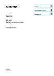
Position of Operator Control and Display Elements
The figure shows the positions of the operator control and display elements on the front
panel of the CP 441-1 and the CP 441-2 communication processors.
CP 441 - 1
X 2
3 4
&3
&3
EXTF
FAULT 1
TxD 1
RxD 1
X 2
3 4
441 - 2AA0x - 0AE0
441 - 1AA0x - 0AE0
INTF
CP 441 - 2
,17)
(;7)
,17)
(;7)
)$8/7
7['
5['
)$8/7
7['
5['
)$8/7
7['
5['
INTF
EXTF
FAULT 1
TxD 1
RxD 1
FAULT 2
TxD 2
RxD 2
,QWHUIDFH
VORW,)
,QWHUIDFH
VORW,)
IF
1
Figure 1-1
IF
1
,QWHUIDFH
VORW,)
IF
2
Position of the operator control and display elements on the CP 441-1 and CP 441-2
communication processors
Point-to-point Link CP 441 Installation and Parameter Assignment
16
Manual, 04/2012, A5E00405449-03
Product Description
1.3 Structure of the CP 441
LEDs
The following LEDs are located on the front panel of the CP 441:
• INTF
(red)
CP 441 signals internal fault
• EXFT
(red)
CP 441 signals external fault
• FAULT 1
(red)
Fault display for Interface IF 1
• TXD 1
(green)
Interface IF 1 is sending
• RXD 1
(green)
Interface IF 1 is receiving
• FAULT 2
(red)
Fault display for Interface IF 2 (CP 441-2)
• TXD 2
(green)
Interface IF 2 is sending (CP 441-2)
• RXD 2
(green)
Interface IF 2 is receiving (CP 441-2)
Slot for Interface Modules
The CP 441-1 contains one slot and the CP 441-2 has two slots for plug-in interface
modules. By exchanging the interface modules, you can adapt the CP 441 to suit the
properties of the communication partners.
There are three types of interface modules:
● RS232 (see section "Properties of the RS232 interface module (Page 18)")
● 20 mA TTY (see section "Attributes of the 20mA TTY interface submodule (Page 19)")
● X27 (RS422/485) (see section "Properties of the X27 (RS422/485) interface module
(Page 20)")
Note
The design of the interface modules for the CP 441 as of order number
6ES7 441-xAA05-0AE0 is different mechanically from earlier interface modules.
Base Connector for S7 Rear Panel Bus
On the back panel of the CP 441 you will find the base connector for the S7-400 rear panel
bus.
The S7-400 rear panel bus is a serial data bus via which the CP 441 communicates with the
modules of the programmable controller and is supplied with the necessary voltage.
Point-to-point Link CP 441 Installation and Parameter Assignment
Manual, 04/2012, A5E00405449-03
17
Product Description
1.4 Properties of the Serial Interface
1.4
Properties of the Serial Interface
Introduction
Two module variants of the communication processor are available with three different
interface modules for adapting to the properties of communication partners.
Standard Cables
Siemens offers standard cables in various lengths for point-to-point link between the
communication processor and a communication partner.
1.4.1
Properties of the RS232 interface module
Definition
The RS232 interface is a voltage interface used for serial data transmission in compliance
with the RS232 standard.
Properties
The RS232 interface module has the following properties and fulfills the following
requirements:
• Type:
Voltage interface
• Front connector:
9-pin sub D male connector with screw-locking
• Max. data transmission
rate:
115.2 kbps
• Max. cable length:
15 m
• Standard:
DIN 66020, DIN 66259, EIA-RS232, CCITT V.24/V.28
• Degree of protection:
IP 00
Please observe the maximum permitted data transmission rates for the modules.
See also
RS232 interface module (Page 233)
Point-to-point Link CP 441 Installation and Parameter Assignment
18
Manual, 04/2012, A5E00405449-03
Product Description
1.4 Properties of the Serial Interface
1.4.2
Attributes of the 20mA TTY interface submodule
Definition
The 20mA TTY interface module is a current-loop interface used for serial data transmission.
Properties
The 20mA TTY interface module has the following attributes and fulfills the following
requirements:
• Type:
Linear current interface
• Front connector:
9-pin subminiature D female with screw interlock
• Max. data transmission rate:
19.2 kbps
• Max. cable length:
1000 m at 9600 bps
• Standard:
DIN 66258 Part 1
• Degree of protection:
IP 00
Please observe the maximum permitted data transmission rates for the modules.
See also
20mA TTY interface submodule (Page 240)
Point-to-point Link CP 441 Installation and Parameter Assignment
Manual, 04/2012, A5E00405449-03
19
Product Description
1.4 Properties of the Serial Interface
1.4.3
Properties of the X27 (RS422/485) interface module
Definition
The X27 (RS 422/485) interface is a differential voltage interface for serial data transmission
in compliance with the X27 standard.
Properties
The X27 (RS422/485) interface module has the following properties and fulfills the following
requirements:
• Type:
Differential voltage interface
• Front connector:
15-pin sub-D female, with screwed interlock
• Max. data transmission rate:
115.2 kbps
• Max. cable length:
1200 m at 19200 bps
• Standard:
DIN 66259 Parts 1 and 3, EIA-RS 422/485, CCITT V.11
• Degree of protection:
IP 00
Please observe the maximum permitted data transmission rates for the modules.
Note
With the RK512 and 3964(R) protocols, the X27 (RS422/485) interface module can only be
used in 4-wire mode.
See also
X27 (RS422/485) interface module (Page 247)
Point-to-point Link CP 441 Installation and Parameter Assignment
20
Manual, 04/2012, A5E00405449-03
Product Description
1.5 Installation Guidelines
1.5
Installation Guidelines
Considerations
The general installation guidelines for S7-400 must be followed (see the S7-400 Automation
System, Installation Installation manual).
To meet the EMC (electromagnetic compatibility) values, the cable shield must be connected
to a shield bus.
Point-to-point Link CP 441 Installation and Parameter Assignment
Manual, 04/2012, A5E00405449-03
21
Product Description
1.5 Installation Guidelines
Point-to-point Link CP 441 Installation and Parameter Assignment
22
Manual, 04/2012, A5E00405449-03
Basic Principles of Serial Data Transmission
2.1
2
Serial transmission of a character
Introduction
The system provides various networking options for the exchange of data between two or
more communication partners. The simplest form of data interchange is via a point-to-point
link between two communication partners.
Point-to-point link
In point-to-point link the communication processor forms the interface between a
programmable controller and a communication partner. In PtP link with communication
processor, data are transferred via serial interface.
Serial Transmission
In serial transmission, the individual bits of each byte of information are transmitted one after
the other in a fixed order.
Unidirectional/Bidirectional Data Traffic
The CP 441 itself handles data transmission with communication partners via its serial
interface. The CP 441 is equipped with three different drivers for this purpose.
● Unidirectional data traffic:
– Printer Driver
● Bidirectional data traffic:
– ASCII driver
– 3964(R) procedure
– RK512 computer link
The CP 441 handles data transmission via the serial interface in accordance with the
interface type and the selected driver.
Unidirectional Data Traffic - Printer Output
In the case of printer output (printer driver), n bytes of user data are output to a printer. No
characters are received. The only exception to this are data flow control characters (e.g.
XON/XOFF).
Point-to-point Link CP 441 Installation and Parameter Assignment
Manual, 04/2012, A5E00405449-03
23
Basic Principles of Serial Data Transmission
2.1 Serial transmission of a character
Bidirectional Data Traffic - Operating Modes
The communication processor has two operating modes for bidirectional data traffic:
● Half-duplex operation (3964(R) procedure, ASCII driver, RK512)
The data is exchanged between the communication partners in both directions
alternately. In half-duplex operation, therefore, at any one time data is being either sent or
received. The exception to this may be individual control characters for data flow control
(e.g. XON/XOFF), which can also be sent during a receive operation or received during a
send operation.
● Full-duplex operation (ASCII driver)
The data is exchanged between the communication partners in both directions
simultaneously, it can both send and receive at the same time. Every communication
partner must be able to operate a send and a receive facility simultaneously.
Only half-duplex mode can be used with an X27 interface module (RS422/485) set to RS485
(2-wire).
Asynchronous Data Transmission
With the communication processor, serial transmission occurs asynchronously. The socalled time base synchronism (a fixed timing code used in the transmission of a fixed
character string) is only upheld during transmission of a character. Each character to be sent
is preceded by a synchronization impulse, or start bit. The length of the start-bit transmission
determines the clock pulse. The end of the character transmission is signaled by the stop bit.
Declarations
As well as the start and stop bits, further declarations must be made between the sending
and receiving partners before serial transmission can take place. These include:
● The data transmission rate
● Character and acknowledgment delay times
● Parity
● Number of data bits
● Number of stop bits
Point-to-point Link CP 441 Installation and Parameter Assignment
24
Manual, 04/2012, A5E00405449-03
Basic Principles of Serial Data Transmission
2.1 Serial transmission of a character
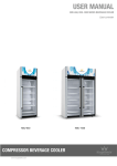
Character frame
Data is transmitted between the communication processor and a communication partner via
the serial interface in a character frame. Various data formats are available for the character
frame. You can set the format for data transmission with the CP 441: Configuration Package
for Point to Point Communication parameter assignment interface.
The figure below shows examples of different data formats for a 10-bit character frame.
GDWDELWVVWDUWELWGDWDELWVVWRSELWV
6LJQDOVWDWH
VWRSELWV
GDWDELWV
VWDUWELW
6LJQDOVWDWH
GDWDELWVVWDUWELWGDWDELWVSDULW\ELWVWRSELW
6LJQDOVWDWH
VWRSELW
SDULW\ELW
GDWDELWV
VWDUWELW
6LJQDOVWDWH
GDWDELWVVWDUWELWGDWDELWVVWRSELW
6LJQDOVWDWH
Figure 2-1
VWRSELW
GDWDELWV
VWDUWELW
6LJQDOVWDWH
10-Bit Character Frame
Point-to-point Link CP 441 Installation and Parameter Assignment
Manual, 04/2012, A5E00405449-03
25
Basic Principles of Serial Data Transmission
2.1 Serial transmission of a character
Character Delay Time
The figure below shows the maximum time permitted between two characters received
within a frame. This is known as the character delay time.
Signal
nth character
(n + 1)th character
Character delay time
1
Time t
Figure 2-2
Character Delay Time
Point-to-point Link CP 441 Installation and Parameter Assignment
26
Manual, 04/2012, A5E00405449-03
Basic Principles of Serial Data Transmission
2.2 Transmission Procedure with a Point-to-Point Connection
2.2
Transmission Procedure with a Point-to-Point Connection
Introduction
When data are transmitted, all communication partners must adhere to a fixed set of rules for
handling and implementing data traffic. The ISO has defined a 7-layer model, which is
recognized as the basis for a worldwide standardization of transmission protocols for
computer-to-computer communication.
ISO 7-Layer Reference Model for Data Transmission
All communication partners must adhere to a fixed set of rules for handling and implementing
data traffic. Such rules are called protocols.
A protocol defines the following:
● Operating mode
Half-duplex or full-duplex operation
● Initiative
Specifies which communication partners can initiate the transmission and under what
conditions.
● Control characters
Specifies the control characters to be used for data transmission.
● Character frame
Specifies which character frames are to be used for data transmission.
● Data backup
Specifies the data backup procedure to be used.
● Character delay time
Specifies the time period within which an incoming character must be received.
● The data transmission rate
Specified in bps.
Procedure
This is the specific process according to which the data is transmitted.
Point-to-point Link CP 441 Installation and Parameter Assignment
Manual, 04/2012, A5E00405449-03
27
Basic Principles of Serial Data Transmission
2.2 Transmission Procedure with a Point-to-Point Connection
ISO 7-Layer Reference Model
The reference model defines the external behavior of the communication partners. Each
protocol layer, except for the lowest one, is embedded in the next one down.
The individual layers are as follows:
1. Physical layer
– Physical conditions for data transmission, e.g. transmission medium, data
transmission rate
2. Data-link layer
– Security procedure for the transmission
– Access modes
3. Network layer
– Network connections
– Specifies the addresses for communication between two partners.
4. Transport layer
– Error-recognition procedure
– Debugging
– Handshaking
5. Session layer
– Establishing communication
– Communication control
– Terminating communication
6. Presentation layer
– Conversion of the standard form of data representation of the communication system
into a device-specific form (data interpretation rules)
7. Application layer
– Defining the communication task and the functions it requires
Processing the Protocols
The sending communication partner runs through the protocols from the highest layer (no. 7
- application layer) to the lowest (no. 1 - physical layer), while the receiving partner
processes the protocols in the reverse order, i.e. starting with layer 1.
Not all protocols have to take all 7 layers into account. If the sending and receiving partners
both use the same protocol, layer 6 can be omitted.
Point-to-point Link CP 441 Installation and Parameter Assignment
28
Manual, 04/2012, A5E00405449-03
Basic Principles of Serial Data Transmission
2.3 Transmission integrity
2.3
Transmission integrity
Introduction
Transmission integrity plays an important role in the transmission of data and in selection of
the transmission procedure. Generally speaking, the more layers of the reference model are
applied, the greater the transmission integrity.
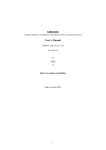
Classifying the Supplied Protocols
The CP 441 can use the following protocols:
● 3964(R) procedure
● RK512 computer link
● ASCII driver
● Printer Driver
The figure below illustrates how these protocols of the CP 441 fit into the reference model:
7UDQVSRUWOD\HU
/D\HU
(YHU\FRUUHFWO\UHFHLYHGFRPPDQG
PHVVDJHIUDPHLVDQVZHUHGZLWKD
UHVSRQVHPHVVDJHIUDPH
5.
/D\HU
1RWSUHVHQWZLWKDSXUH
SRLQWWRSRLQWFRQQHFWLRQ
7KHGDWDE\WHVDUHWUDQVPLWWHGZLWK
56WDUWDQGVWRSELWVDUHDGGHG
LQWKHHYHQWRIDQHUURUWKHWUDQVPLVVLRQ
PD\EHUHSHDWHG
Figure 2-3
7KHSK\VLFDOWUDQVPLVVLRQRWWKH
GDWDE\WHVLVGHILQHG
$6&,,GULYHU
3K\VLFDOOD\HU
/D\HU
3ULQWHUGULYHU
/D\HU
5
'DWDOLQNOD\HU
Position of the supplied protocols of the CP 441 in the reference model
Point-to-point Link CP 441 Installation and Parameter Assignment
Manual, 04/2012, A5E00405449-03
29
Basic Principles of Serial Data Transmission
2.3 Transmission integrity
Transmission Integrity with the Printer Driver
Data Integrity When Using the Printer Driver:
● No data integrity precautions are taken for data transmission with the printer driver.
● To prevent data from being lost in the event of the printer receive buffer overflowing, you
can work with data flow control (XON/XOFF, RTS/CTS).
● When data is output to the printer, the printer's BUSY signal is evaluated. The CP 441
receives the BUSY signal as a CTS signal and evaluates it in the same way (see ASCII
driver). Note when using CTS/RTS data flow control, that you must set the polarity of the
BUSY signal to CTS = "OFF" on the printer (only with the RS232C interface).
Transmission Integrity with the ASCII Driver
Data Integrity When Using the ASCII Driver:
● When data is transmitted via the ASCII driver, there are no data integrity precautions
other than the use of a parity bit (can also be canceled, depending on how the character
frame is set). This means that, although this type of data transport has a very efficient
throughput rate, security is not guaranteed.
● Using the parity bit ensures that the inversion of a bit in a character to be transmitted can
be recognized. If two or more bits of a character are inverted, this error can no longer be
detected.
● To increase transmission integrity, a checksum and length specification for a frame can
be employed. These measures must be implemented by the user.
● A further increase in data integrity can be achieved by means of acknowledgment frames
in response to send or receive frames. This is the case with high-level protocols for data
communication (see ISO 7-layer reference model).
Transmission Integrity with 3964R
Enhanced Data Integrity with the 3964R Procedure:
● The hamming distance with the 3964R is 3. This measures the integrity of data
transmission.
● The 3964R procedure ensures high transmission integrity on the data line. This high
integrity is achieved by means of a fixed frame set-up and clear-down as well as the use
of a block check character (BCC).
Two different procedures for data transmission can be used, either with or without a block
check character:
● data transmission without a block check character: 3964
● data transmission with a block check character: 3964R
In this manual, the designation 3964(R) is used when descriptions and notes refer to both
data transmission procedures.
Point-to-point Link CP 441 Installation and Parameter Assignment
30
Manual, 04/2012, A5E00405449-03
Basic Principles of Serial Data Transmission
2.3 Transmission integrity
Performance Limits with 3964R
● Further processing of the send/receive data by the PLC program in the communication
partner is not guaranteed. You can only ensure this by using a programmable
acknowledgment mechanism.
● The block check of the 3964R procedure (EXOR operation) cannot detect missing zeros
(as a whole character) because a zero in the EXOR operation does not affect the result of
the calculation.
Although the loss of an entire character (this character has to be a zero!) is highly
unlikely, it could possibly occur under very bad transmission conditions.
You can protect a transmission against such errors by sending the length of the data
frame along with the data itself, and having the length checked at the other end.
● Such transmission errors are ruled out when the RK512 computer link is used for data
transmission, because here (unlike the 3964(R) procedure) further processing is
acknowledged via response frames (e.g. stored in the destination data block) and the
send data length is recorded in the frame header. This enables the RK512 to achieve a
higher Hamming distance (of 4) than that with 3964R.
Transmission integrity with RK512
Very high data security using RK512:
● The Hamming distance with the RK512 and 3964R is 4. The Hamming distance is a
measure of the integrity for a data transmission.
● Using the RK512 computer link ensures high transmission integrity on the transmission
line (because RK512 uses the 3964R procedure for data transport).
● Further processing at the communication partner is ensured (because the RK512
interpreter checks the additional length specification in the header and, after storing the
data in the destination data area of the communication partner, generates a frame
acknowledging the success or failure of the data transport).
● The RK512 computer link independently guarantees the correct use of the 3964R
procedure and the analysis/addition of the length specification as well as the generation
of the response frames. There is no user handling! All you need to do is evaluate the
positive/negative final acknowledgment.
Performance limits with RK512
● Using the RK512 computer link provides maximum data security! Another advantage, for
example, is the use of other block check mechanisms (such as CRC checks).
Point-to-point Link CP 441 Installation and Parameter Assignment
Manual, 04/2012, A5E00405449-03
31
Basic Principles of Serial Data Transmission
2.4 Data Transmission with the 3964(R) Procedure
2.4
Data Transmission with the 3964(R) Procedure
Introduction
The 3964(R) procedure controls point-to-point data exchange between the communication
processor and a communication partner. As well as the physical layer (layer 1), the 3964(R)
procedure also incorporates the data-link layer (layer 2).
Startup
The figure below illustrates the start-up of the 3964(R) procedure.
3RZHUXSDIWHUUHVWDUWRIWKH
&38RUYROWDJHUHFRYHU\
(YDOXDWHSDUDPHWHUDVVLJQPHQW
,QLWLDOL]HLQWHUIDFH
6HQG1$.
*
Figure 2-4
Flow diagram of the start-up of the 3964(R) procedure
Point-to-point Link CP 441 Installation and Parameter Assignment
32
Manual, 04/2012, A5E00405449-03
Basic Principles of Serial Data Transmission
2.4 Data Transmission with the 3964(R) Procedure
2.4.1
Control characters
Introduction
The RK 512 computer connection provides a very high degree of data integrity. During data
transmission, the 3964(R) procedure adds control characters to the information data (dataconnection layer). These control characters allow the communication partner to check
whether the data has arrived complete and without errors.
The Control Characters of the 3964(R) Procedure
The 3964(R) procedure analyzes the following control codes:
● STXStart of Text; start of character string for transfer
● DLEData Link Escape; data connection escape
● ETXEnd of Text; end of character string for transfer
● BCCBlock Check Character (3964R only)
● NAKNegative Acknowledge
Note
If DLE is transmitted as an information string, it is sent twice so that it can be
distinguished from the control code DLE during connection setup and release on the send
line (DLE duplication). The receiver then reverses the DLE duplication.
Priority
With the 3964(R) procedure, one communication partner must be assigned a higher priority
and the other partner a lower priority. If both partners begin connection setup at the same
time, the partner with the lower priority will defer its send request.
Point-to-point Link CP 441 Installation and Parameter Assignment
Manual, 04/2012, A5E00405449-03
33
Basic Principles of Serial Data Transmission
2.4 Data Transmission with the 3964(R) Procedure
2.4.2
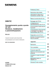
Block Checksum
Block Checksum
With the 3964R transmission protocol, data integrity is increased by the additional sending of
a block check character (BCC).
0HVVDJHIUDPH
67;'DWD'/((7;%&&
+ൺ+ൺ+ൺ+ൺ+ൺ+ൺ+
Figure 2-5
;25 ;25 ;25 ;25 %&&ൺ
Block Checksum
The block checksum is the even longitudinal parity (EXOR operation on all data bytes) of a
sent or received block. Its calculation begins with the first byte of user data (first byte of the
message frame) after the connection setup, and ends after the DLE ETX code on connection
release.
Note
If DLE duplication occurs, the DLE code is accounted for twice in the BCC calculation.
Point-to-point Link CP 441 Installation and Parameter Assignment
34
Manual, 04/2012, A5E00405449-03
Basic Principles of Serial Data Transmission
2.4 Data Transmission with the 3964(R) Procedure
2.4.3
Sending data with 3964(R)
Process of Data Transmission when Sending
The figure below illustrates the transmission sequence when data is sent with the 3964(R)
procedure.
&3
&RPPXQLFDWLRQSDUWQHU
6WDUWFRGH+
3RVDFNQRZOHGJPHQW+
VWGDWDE\WH
QGGDWDE\WH
ವ
ವ
QWKGDWDE\WH
67;
'/(
VWE\WH
QGE\WH
ವ
ವ
QWKE\WH
(QGFRGH+
(QGFRGH+
5RQO\
3RVDFNQRZOHGJPHQW+
'/(
(7;
%&&
'/(
Figure 2-6
&RQQHFWLRQ
VHWXS
8VHU
1XW]
DWHQ
GGDWD
&RQQHFWLRQ
UHOHDVH
Data traffic when sending with the 3964(R) procedure
Establishing a Send Connection
To establish the connection, the 3964(R) procedure sends the control character STX. If the
communication partner responds with the DLE code before the acknowledgment delay time
expires, the procedure switches to send mode.
If the communication partner answers with NAK or with any other control code (except for
DLE or STX), or the acknowledgment delay time expires without a response, the procedure
repeats the connection setup. After the defined number of unsuccessful connection attempts,
the procedure aborts the connection setup and sends the NAK code to the communication
partner. The CP 441 enters an appropriate error number in its SYSTAT area.
Sending Data
If a connection is successfully established, the user data contained in the output buffer of the
communication processor is sent to the communication partner with the chosen transmission
parameters. The partner monitors the times between incoming characters. The interval
between two characters must not exceed the character delay time.
If the communication partner sends the NAK control code during an active send operation,
the procedure aborts its transmission of the block and tries again as described above,
beginning with connection setup. If a different code is sent, the procedure first waits for the
character delay time to expire and then sends the NAK code to change the mode of the
communication partner to idle. Then the procedure starts to send the data again with the
connection setup STX.
Point-to-point Link CP 441 Installation and Parameter Assignment
Manual, 04/2012, A5E00405449-03
35
Basic Principles of Serial Data Transmission
2.4 Data Transmission with the 3964(R) Procedure
Releasing a Send Connection
Once the contents of the buffer have been sent, the procedure adds the codes DLE, ETX
and with the 3964R only the block checksum BCC as the end identifier, and waits for an
acknowledgment code. If the communication partner sends the DLE code within the
acknowledgment delay time, the data block has been received without errors. If the
communication partner responds with NAK, any other code (except DLE), or a damaged
code, or if the acknowledgment delay time expires without a response, the procedure starts
to send the data again with the connection setup STX.
After the defined number of attempts to send the data block, the procedure stops trying and
sends an NAK to the communication partner. The CP 441 reports the error in the SYSTAT
error-signaling area.
Point-to-point Link CP 441 Installation and Parameter Assignment
36
Manual, 04/2012, A5E00405449-03
Basic Principles of Serial Data Transmission
2.4 Data Transmission with the 3964(R) Procedure
Sending with the 3964(R) Procedure
The figure below illustrates sending with the 3964(R) procedure.
*
,QWHQWLRQWR
VHQG
*
*
6HQG1$.
: 6HQG1$.
[!
[ [ 6HQG67;
:
[
6WDUW7$'7
+LJK
SULRULW\
67;
7!7$'7
FKDUDFWHUH[FHSW
:DLWIRU'/( '/(67;RU
DFNQRZOHGJ LQYDOLG
/RZ
SULRULW\
'/(
5HFHLSWQRW
SHUPLWWHG
6HQGEORFN
SRVV
GXSOLFDWH'/(
[!
[ 6HQG1$.
6HQG'/(
(7;
5
6HQG%&&
6WDUW7$'7
:DLWIRU'/(
DFNQRZOHGJ
7!7$'7
FKDUDFWHUH[FHSW
'/(RULQYDOLG
FKDUDFWHU
'/(
6HQGLOHWHG
*
%&&RQO\ZLWK5
[ VHWXSDWWHPSWFRXQW
7$'7 PV57$'7 V
: WUDQVPLVVLRQDWWHPSWFRXQW
,PPHGLDWHUHWXUQWRLQLWLDOVWDWHDWOLQHEUHDN%5($.
Figure 2-7
Flow diagram of sending with the 3964(R) procedure
Point-to-point Link CP 441 Installation and Parameter Assignment
Manual, 04/2012, A5E00405449-03
37
Basic Principles of Serial Data Transmission
2.4 Data Transmission with the 3964(R) Procedure
C: Counter for connection attempts
R: Counter for retries
D: Default state
W: Waiting for character reception
Point-to-point Link CP 441 Installation and Parameter Assignment
38
Manual, 04/2012, A5E00405449-03
Basic Principles of Serial Data Transmission
2.4 Data Transmission with the 3964(R) Procedure
2.4.4
Receiving data with 3964(R)
Process of Data Transmission when Receiving
The figure below illustrates the transmission sequence when data is received with the
3964(R) procedure.
&RPPXQLFDWLRQSDUWQHU
67;
'/(
&RQQHFWLRQ
VHWXS
VWE\WH
QGE\WH
ವ
8VHU
GDWD
&RQQHFWLRQ
UHOHDVH
Figure 2-8
&3
6WDUWFRGH+
3RVDFNQRZOHGJPHQW+
VWGDWDE\WH
QGGDWDE\WH
ವ
QWKE\WH
ವ
ವ
QWKGDWDE\WH
'/(
(7;
%&&
'/(
(QGFRGH+
(QGFRGH+
5RQO\
3RVDFNQRZOHGJPHQW+
Data traffic when receiving with the 3964(R) procedure
Note
As soon as it is ready, the 3964(R) procedure sends a single NAK to the communication
partner to set the latter to idle.
Establishing a Receive Connection
In idle mode, when there is no send request to be processed, the procedure waits for the
communication partner to establish the connection.
If no empty receive buffer is available during a connection setup with STX, a wait time of 400
ms is started. If there is still no empty receive buffer after this time has expired, the system
program reports the error (error number in SYSTAT). and the procedure sends a NAK and
returns to idle mode. Otherwise, the procedure sends a DLE and receives the data as
described above.
If the idle procedure receives any control code except for STX or NAK, it waits for the
character delay time to expire, then sends the code NAK. The CP 441 reports the error in the
SYSTAT error-signaling area.
Point-to-point Link CP 441 Installation and Parameter Assignment
Manual, 04/2012, A5E00405449-03
39
Basic Principles of Serial Data Transmission
2.4 Data Transmission with the 3964(R) Procedure
Receiving data
After a successful connection setup, the receive characters that are arrive are stored in the
receive buffer. If two consecutive DLE codes are received, only one of these is stored in the
receive buffer.
After each receive character, the procedure waits out the character delay time for the next
character. If this period expires before another character is received, an NAK is sent to the
communication partner. The CP 441 reports the error in the SYSTAT error-signaling area.
The 3964(R) procedure does not initiate a repetition.
If transmission errors occur during receiving (lost character, frame error, parity error, etc.),
the procedure continues to receive until the connection is shut down, then an NAK is sent to
the communication partner. A repetition is then expected. If the undamaged block still cannot
be received after the number of transmission attempts defined in the static parameter set, or
if the communication partner does not start the repetition within a block wait time of 4
seconds, the procedure aborts the receive operation. The CP 441 reports the first erroneous
transmission and the final abortion in the SYSTAT error-signaling area.
Releasing a Receive Connection
When the 3964 procedure detects a DLE ETX character string, it ends the receiving
operation and confirms the successfully received block by sending a DLE signal to the
communication partner. When errors are found in the received data, it outputs a NAK signal
to the communication partner. A repetition is then expected.
If the 3964R procedure recognizes the string DLE ETX BCC, it stops receiving and
compares the received block check character with the longitudinal parity calculated
internally. If the BCC is correct and no other receive errors have occurred, the CP sends the
code DLE to the communication partner. If the BCC is correct and no other receive errors
have occurred, the 3964R procedure sends a DLE and returns to idle mode. If the BCC is
faulty or a different receiving error occurs, an NAK is sent to the communication partner. A
repetition is then expected.
Point-to-point Link CP 441 Installation and Parameter Assignment
40
Manual, 04/2012, A5E00405449-03
Basic Principles of Serial Data Transmission
2.4 Data Transmission with the 3964(R) Procedure
Receiving with the 3964(R) Procedure
The figure below illustrates receiving with the 3964(R) procedure.
&KDUDFWHUVH[FHSW
67;1$.
,QWHQWLRQWRVHQG
*
5HFHLYH
67;
5HSHWLWLRQ
H[SHFWHG
1RWH
1$.
:
,QLWLDOL]DWLRQ
FRQIOLFWORZ
SULRULW\
6WDUW
71$.7,0
:DLW
%XIIHUIUHH
7!71$.7,0
%XIIHUQRWIUHH
6HQG'/(
6HQG1$.
*
71$.7,0 PV
: WUDQVPLVVLRQDWWHPSWFRXQWHU
,PPHGLDWHUHWXUQWRLQLWLDOVWDWHDWOLQHEUHDN%5($.
Figure 2-9
Flow chart of receiving with the 3964(R) procedure (part 1)
R: Counter for retries
D: Default state
Point-to-point Link CP 441 Installation and Parameter Assignment
Manual, 04/2012, A5E00405449-03
41
Basic Principles of Serial Data Transmission
2.4 Data Transmission with the 3964(R) Procedure
Receiving with the 3964(R) Procedure
The figure below illustrates receiving with the 3964(R) procedure.
6WDUW7FKDUGHOD\WLPH
&RUUHFW
FKDUDFWHU
H[FHSWIRU
'/(
1RWH
1$.
:DLWWR
UHFHLYH
FKDUDFWHUV
,QYDOLGFKDUDFWHU
7!7FKDUGHOD\WLPH
'/(
6WDUW7FKDUGHOD\WLPH
'XDO'/(
1RWH1$.
7!7FKDUGHOD\WLPH
:DLWIRU
(7;
&KDUDFWHUV
H[FHSW
(7;'/(
(7;
5
6WDUW7FKDUGPH
7!7FKDUGHOD\WLPH
:DLWIRU %&&LQFRUUHFW
%&&
%&&
1$.QRWHG
,QLWLDOL]DWLRQFRQIOLFW
QRWHGORZSULRULW\
6HQG1$.
6HQG'/(
5HFHLSWFRPSOHWHG
:!
: 1RWHUHSHWLWLRQH[SHFWHG
VWDUW7%ORFN
*
7!7%ORFN
:DLWIRU
67;
7LPHV7FKDUGHOD\WLPH PV7%ORFN V
: WUDQVPLVVLRQDWWHPSWFRXQW
%&&ZLWK5RQO\
,PPHGLDWHUHWXUQWRLQLWLDOVWDWHDWOLQHEUHDN%5($.
Figure 2-10
67;
*
Flow chart of receiving with the 3964(R) procedure (part 2)
R: Counter for retries
D: Default state
W: Waiting for character reception
Point-to-point Link CP 441 Installation and Parameter Assignment
42
Manual, 04/2012, A5E00405449-03
Basic Principles of Serial Data Transmission
2.4 Data Transmission with the 3964(R) Procedure
2.4.5
Handling Erroneous Data
Handling Erroneous Data
The figure below illustrates how erroneous data is handled with the 3964(R) procedure.
&3
&RPPXQLFDWLRQSDUWQHU
5UHFHLYLQJGDWD
6WDUWFRGH+
&RQQHFWLRQ
VHWXS
3RVDFNQRZOHGJHPHQW+
67;
'/(
VWGDWDE\WH
ವ
QWKGDWDE\WH
ವ
ವ
VWE\WH
ವ
QWK%\WH
ವ
ವ
(QGFRGH+
'/(
(7;
%&&
1$.
(QGFRGH+
5RQO\
1HJIHHGEDFN+
8VHU
GDWD
&RQQHFWLRQ
UHOHDVH
7
&RQQHFWLRQUHWU\
Figure 2-11
Data traffic when receiving erroneous data
When the string DLE ETX BCC is received, the CP 441 compares the BCC of the
communication partner with its own internally calculated value. If the BCC is correct and no
other receive errors occur, the CP 441 responds with DLE.
Otherwise, the CP 441 responds with an NAK and waits the block wait time (T) of 4 seconds
for a new attempt. If after the defined number of transmission attempts the block cannot be
received, or if no further attempt is made within the block wait time, the CP 441 aborts the
receive operation.
Point-to-point Link CP 441 Installation and Parameter Assignment
Manual, 04/2012, A5E00405449-03
43
Basic Principles of Serial Data Transmission
2.4 Data Transmission with the 3964(R) Procedure
initialization conflict
The figure below illustrates the transmission sequence during an initialization conflict.
&3
ORZSULRULW\
&RPPXQLFDWLRQSDUWQHU
KLJKHUSULRULW\
6WDUWFRGH+
6WDUWFRGH+
3RVDFNQRZOHGJPHQW+
67;
67;
'/(
VWGDWDE\WH
QGGDWDE\WH
Ⴠ
Ⴠ
VWE\WH
QGE\WH
Ⴠ
Ⴠ
QWKGDWDE\WH
QWKE\WH
(QGFRGH+
(QGFRGH+
5RQO\
3RVDFNQRZOHGJPHQW+
'/(
&RQQHFWLRQ
VHWXS
8VHU
GDWD
(7;
%&&
'/(
&RQQHFWLRQ
UHOHDVH
67;
'/(
&RQQHFWLRQ
VHWXS
QGVHWXSDWWHPSW
6WDUWFRGH+
3RVDFNQRZOHGJPHQW+
Figure 2-12
Data traffic during an initialization conflict
If a device responds to the communication partner's send request (code STX) within the
acknowledgment delay time by sending the code STX instead of the acknowledgment DLE
or NAK, an initialization conflict occurs. Both devices want to execute a send request. The
device with the lower priority withdraws its send request and responds with the code DLE.
The device with the higher priority sends its data in the manner described above. Once the
connection has been released, the lower-priority device can execute its send request.
To be able to resolve initialization conflicts you must set different priorities for the
communication partners.
Point-to-point Link CP 441 Installation and Parameter Assignment
44
Manual, 04/2012, A5E00405449-03
Basic Principles of Serial Data Transmission
2.4 Data Transmission with the 3964(R) Procedure
Procedure errors
The procedure recognizes both errors which are caused by the communication partner and
errors caused by faults on the line.
In both cases, the procedure makes repeated attempts to send/receive the data block
correctly. If this is not possible within the maximum number of transmission attempts set (or
if a new error status occurs), the procedure aborts the send or receive process. It reports the
error number of the first recognized error and returns to idle mode. The CP 441 reports the
error in the SYSTAT error-signaling area.
If the CP 441 frequently reports the error number in the SYSTAT for send and receive
repetitions, this implies occasional disturbances in the data traffic. The large number of
transmission attempts compensates for this, however. In this case you are advised to check
the transmission link for possible sources of interference, because frequent repetitions
reduce the user-data rate and integrity of the transmission. The disturbance could also be
caused, however, by a malfunction on the part of the communication partner.
If the receive connection is interrupted, the system program reports a BREAK status (in
SYSTAT). No repeat is started. The BREAK status in the SYSTAT is automatically reset as
soon as the connection is restored on the line.
For every recognized transmission error (lost character, frame or parity error), a standard
number is reported, regardless of whether the error was detected during sending or receiving
of a data block. The error is only reported, however, following unsuccessful repetitions.
If the damaged character is received when the procedure is idle, the system program reports
the error (error number in the SYSTAT) to inform you of major interference in the data
transmission circuit.
See also
Diagnostics via the error signaling area SYSTAT (Page 195)
Point-to-point Link CP 441 Installation and Parameter Assignment
Manual, 04/2012, A5E00405449-03
45
Basic Principles of Serial Data Transmission
2.5 Data transmission with the RK512 computer link
2.5
Data transmission with the RK512 computer link
Introduction
The RK512 computer link controls data transmission via a point-to-point link between the CP
441 and a communication partner.
Unlike the 3964(R) procedure, the RK512 computer link includes not only the physical layer
(layer 1), and the data link layer (layer 2), but also the transport layer (layer 4) of the ISO
reference model. The RK512 computer link also offers greater data security and better
addressing options.
Response frame
The RK512 computer link answers each correctly received command frame with a response
frame to the CPU (transport layer). This allows senders to check whether their data has
arrived undamaged at the CPU or whether the data they require is available on the CPU.
Command frame
Command frames are either SEND/PUT or GET frames.
SEND/PUT frame
A SEND/PUT frame is created when the CP 441 sends a command frame with user data,
and the communication partner replies with a response frame without user data.
GET frame
A GET frame is created when the CP 441 sends a command frame without user data, and
the communication partner replies with a response frame with user data.
Continuation frame
If the volume of data exceeds 128 bytes, SEND/PUT and GET frames are automatically
accompanied by continuation frames.
Frame header
With RK512, each frame begins with a frame header. It can contains frame IDs, information
on the data destination and source and an error number.
Point-to-point Link CP 441 Installation and Parameter Assignment
46
Manual, 04/2012, A5E00405449-03
Basic Principles of Serial Data Transmission
2.5 Data transmission with the RK512 computer link
Structure of the frame header
The table below indicates the structure of the header of the command frame.
Table 2- 1
byte
1
Format of the frame header for the command frame (RK512)
Meaning
The frame ID in command frames (00H),
in continuation command frames (FFH)
2
3
Frame ID (00H)
'A' (41H) for SEND/PUT request with destination DB or
'O' (4FH) for SEND request with destination DX or
'E' (45H) for GET request
4
Data to be transmitted consists of:
'D' (44H)=data block
'I' (45H) = Input bytes
'O' (41H) = Output bytes
'M' (4DH)=flag bytes
'C' (5AH)=counter cells
'T' (54H) = Time cells
(The entry for send requests with BSEND and PUT is always "D", irrespective of the
areas from which the data come.)
5 and 6
Data destination of SEND/PUT request or data source of GET request e.g. byte 5 = DB
no., byte 6 = DW no.
(RK512 addressing describes data source and destination with word limits. Conversion
to byte addresses in SIMATIC S7 is automatic.)
7 and 8
Length of high byte Length of data to be transmitted according to type in bytes or
Length of low byte words
9
Byte number of the interprocessor communication flag (You can specify interprocessor
communication flags for send requests with "BSEND". In the block of the partner you
cannot specify interprocessor communication flags, because the CP itself does not
support them.)
FFH is displayed if you have not specified an interprocessor communication flag.
10
Bit 0 to 3: Bit number of the interprocessor communication flag (You can specify
interprocessor communication flags for send requests with "BSEND". You cannot
specify interprocessor communication flags in the block of the partner because the CP
itself does not support them.).
The protocol enters FH here if you have not specified an interprocessor communication
flag.
Bit 4 to 7: CPU number (number from 1 to 4) (The CPU number 0 is supported as of
STEP 7, Version 4.0.);
If you have not specified a CPU number but you have specified an interprocessor
communication flag, OH is displayed here; if you specified neither a CPU number nor an
interprocessor communication flag, FH is shown here.
The letters in bytes 3 and 4 are ASCII characters.
The header of the continuation command frame consists of bytes 1 to 4 only.
Point-to-point Link CP 441 Installation and Parameter Assignment
Manual, 04/2012, A5E00405449-03
47
Basic Principles of Serial Data Transmission
2.5 Data transmission with the RK512 computer link
Response frame
Once the command frame has been transmitted, the RK512 waits for a response frame from
the communication partner within the monitoring time. The length of the monitoring time
amounts to 20 s regardless of the data transmission rate.
This monitoring time can be reduced by setting the parameters in the "RK512" registry dialog
of the parameter assignment interface. By selecting the "dependent on data transmission
rate" option, monitoring is performed with the following maximum waiting times.
Data transmission rate
Time monitoring
300 bps
10 s
600 bps
7 sec
1200 bps
5 sec
as of 38 400 bps
3 sec
The "grayed" "Maximum wait time" field is used only for showing the configured monitoring time and
cannot be edited!
Structure and contents of the response frame
The response frame consists of 4 bytes and contains information on the progress of the
request.
byte
1
Meaning
Frame ID in response frames (00H),
in continuation response frames (FFH)
2
Frame ID (00H)
3
Displays 00H
4
Error number of the communication partner in the response frame:
•
00H if transmission was error-free
• > 00H error number
The error number in the response frame automatically causes an error number to be entered
in the SYSTAT.
See also
Communication via System Function Blocks (Page 137)
Diagnostics via the error signaling area SYSTAT (Page 195)
Error Numbers in the Response Message Frame (Page 209)
Point-to-point Link CP 441 Installation and Parameter Assignment
48
Manual, 04/2012, A5E00405449-03
Basic Principles of Serial Data Transmission
2.5 Data transmission with the RK512 computer link
2.5.1
Sending data with RK512
Process of Data Transmission when Sending
The figure below shows the transmission sequence when sending data with a response
frame using the RK512 computer link.
&3
&RPPXQLFDWLRQSDUWQHU
6(1'387PHVVDJHIUDPH
6WDUWFRGH+
3RVDFNQRZOHGJPHQW+
+
+
6(1'387UHTXHVW+
'DWDEORFN+
'DWDGHVWLQDWLRQ'%$+
':+
/HQJWK+
':+
1R.0))+
&38RQO\)+
67;
'/(
VWE\WH
QGE\WH
UGE\WH
WKE\WH
WKE\WH
WKE\WH
WKE\WH
WKE\WH
&RQQHFWLRQ
VHWXS
0HVVDJH
IUDPH
KHDGHU
WKE\WH
WKE\WH
VWGDWDE\WH
QGGDWDE\WH
WKE\WH
WKE\WH
ವ
ವ
QWKGDWDE\WH
ವ
ವ
QWKE\WH
(QGFRGH+
(QGFRGH+
ZLWKEORFNFKHFNRQO\
3RVDFNQRZOHGJPHQW+
'/(
(7;
%&&
8VHUGDWD
&RQQHFWLRQ
UHOHDVH
'/(
5HVSRQVHPHVVDJHIUDPH
6WDUWFRGH+
3RVDFNQRZOHGJPHQW+
67;
+
+
+
(UURUFRGH+
VWE\WH
QGE\WH
UGE\WH
WKE\WH
5HVSRQVH
PHVVDJH
IUDPH
KHDGHU
(QGFRGH+
'/(
(7;
%&&
&RQQHFWLRQ
UHOHDVH
(QGFRGH+
ZLWKEORFNFKHFNRQO\
3RVDFNQRZOHGJHPHQW+
Figure 2-13
'/(
&RQQHFWLRQ
VHWXS
'/(
Data traffic when sending with a response frame
Point-to-point Link CP 441 Installation and Parameter Assignment
Manual, 04/2012, A5E00405449-03
49
Basic Principles of Serial Data Transmission
2.5 Data transmission with the RK512 computer link
Sending data
The SEND/PUT request is executed in the following sequence:
● Active partner
Sends a SEND/PUT frame. This contains a frame header and data.
● Passive partner
Receives the frame, checks the header and the data, and acknowledges it with a
response frame after passing the data on to the CPU.
● Active partner
Receives the response frame.
If the volume of user data exceeds 128 bytes, the active partner sends a continuation
SEND/PUT frame. This contains byte 1 to 4 of the frame header.
● Passive partner
Receives the continuation SEND/PUT frame, checks the header and the data, and
acknowledges it with a continuation response frame after passing the data on to the CPU.
Note
If the CPU receives an error SEND/PUT frame or if an error has occurred in the frame
header, the communication partner enters an error number in the 4th byte of the
response frame. This does not apply when protocol errors occur.
Point-to-point Link CP 441 Installation and Parameter Assignment
50
Manual, 04/2012, A5E00405449-03
Basic Principles of Serial Data Transmission
2.5 Data transmission with the RK512 computer link
Continuation SEND/PUT frames
A continuation SEND/PUT frame is started if the volume of data exceeds 128 bytes. The
process is the same as for SEND/PUT frames.
If more than 128 bytes are sent, the extra bytes are automatically transmitted in one or more
continuation frames.
The figure below shows the data transmission sequence when sending a continuation
SEND/PUT frame with a continuation response frame.
&3
&RPPXQLFDWLRQSDUWQHU
&RQWLQXDWLRQ6(1'387PHVVDJHIUDPH
6WDUWFRGH+
3RVDFNQRZOHGJ
PHQW+
67;
'/(
&RQWLQXDWLRQPHVVDJHIUDPH))+
+
6(1'387UHTXHVW+
'DWDEORFN+
VWE\WH
QGE\WH
UGE\WH
WKE\WH
WKGDWDE\WH
WKGDWDE\WH
ವ
ವ
WKE\WH
WKE\WH
ವ
ವ
QWKGDWDE\WH
QWKE\WH
(QGFRGH+
(QGFRGH+
ZLWKEORFNFKHFNRQO\
3RVDFNQRZOHGJHPHQW+
'/(
(7;
%&&
'/(
&RQQHFWLRQ
VHWXS
0HVVDJH
IUDPHKHDGHU
8VHUGDWD
&RQQHFWLRQ
UHOHDVH
&RQWLQXDWLRQUHVSRQVHPHVVDJHIUDPH
6WDUWFRGH+
67;
3RVDFNQRZOHGJPHQW+
'/(
&RQWLQXDWLRQUHVSRQVH
PHVVDJHIUDPH))+
+
+
(UURUQXPEHU+
VWE\WH
QGE\WH
UGE\WH
WKE\WH
(QGFRGH+
(QGFRGH+
ZLWKEORFNFKHFNRQO\
3RVDFNQRZOHGJHPHQW+
Figure 2-14
'/(
(7;
%&&
&RQQHFWLRQ
VHWXS
5HVSRQVH
PHVVDJH
IUDPHKHDGHU
&RQQHFWLRQ
UHOHDVH
'/(
Sequence of a continuation SEND/PUT frame with a continuation response frame
Point-to-point Link CP 441 Installation and Parameter Assignment
Manual, 04/2012, A5E00405449-03
51
Basic Principles of Serial Data Transmission
2.5 Data transmission with the RK512 computer link
2.5.2
Fetching data with RK512
Procedure for fetching data with RK512
The figure below shows the transmission sequence when fetching data with a response
frame using the RK512 computer link.
&3
&RPPXQLFDWLRQSDUWQHU
*(7PHVVDJHIUDPH
6WDUWFRGH+
3RVDFNQRZOHGJHPHQW+
+
+
*(7UHTXHVW+
'DWDEORFN+
'DWDVRXUFH'%+
':+
/HQJWK+
':+
1R&0))+
67;
'/(
VWE\WH
QGE\WH
UGE\WH
WKE\WH
WKE\WH
WKE\WH
WKE\WH
WKE\WH
&RQQHFWLRQ
VHWXS
0HVVDJH
IUDPH
KHDGHU
WKE\WH
&38RQO\)+
WKE\WH
(QGFRGH+
(QGFRGH+
2QO\ZLWKEORFNFKHFN
'/(
(7;
%&&
3RVDFNQRZOHGJHPHQW+
'/(
&RQQHFWLRQ
UHOHDVH
5HVSRQVHPHVVDJHIUDPHZLWKGDWD
6WDUWFRGH+
67;
'/(
&RQQHFWLRQ
VHWXS
VWE\WH
QGE\WH
UGE\WH
WKE\WH
5HVSRQVH
PHVVDJH
IUDPH
KHDGHU
8VHU
GDWD
QWKGDWDE\WH
WKE\WH
WKE\WH
ವ
ವ
QWKE\WH
(QGFRGH+
(QGFRGH+
2QO\ZLWKEORFNFKHFN
'/(
(7;
%&&
3RVDFNQRZOHGJHPHQW+
'/(
3RVDFNQRZOHGJHPHQW+
+
+
+
(UURUFRGH+
VWGDWDE\WH
QGGDWDE\WH
ವ
ವ
Figure 2-15
&RQQHFWLRQ
UHOHDVH
Data traffic when fetching with a response frame
Point-to-point Link CP 441 Installation and Parameter Assignment
52
Manual, 04/2012, A5E00405449-03
Basic Principles of Serial Data Transmission
2.5 Data transmission with the RK512 computer link
Fetching data
The GET request is executed in the following sequence:
● Active partner
Sends a GET frame. This contains a frame header.
● Passive partner
Receives the frame, checks the header, fetches the data from the CPU, and
acknowledges this with a response frame containing the data. This contains the data.
● Active partner
Receives the response frame.
If the volume of user data exceeds 128 bytes, the active partner sends a continuation
GET frame. This contains byte 1 to 4 of the frame header.
● Passive partner
Receives the continuation GET frame, checks the frame header and acknowledges this
with a continuation response frame containing further data.
If there is an error number (not equal to 0) in the 4th byte, the response frame does not
contain any data.
If more than 128 bytes are requested, the extra bytes are automatically fetched in one or
more continuation frames.
Note
If the CPU receives an error GET frame or if an error has occurred in the frame header, the
communication partner enters an error number in the 4th byte of the response frame. This
does not apply when protocol errors occur.
Point-to-point Link CP 441 Installation and Parameter Assignment
Manual, 04/2012, A5E00405449-03
53
Basic Principles of Serial Data Transmission
2.5 Data transmission with the RK512 computer link
Continuation GET frame
The figure below shows the transmission sequence when fetching data with a continuation
response frame.
&3
&RPPXQLFDWLRQSDUWQHU
&RQWLQXDWLRQ*(7IUDPH
6WDUWFKDUDFWHU+
SRVDFNQRZOHGJPHQW+
67;
'/(
&RQWLQXDWLRQIUDPH))+
+
*(7UHTXHVW+
'DWDEORFN+
VWE\WH
QGE\WH
UGE\WH
WKE\WH
'HOLPLWHU+
'HOLPLWHU+
%ORFNFKHFNRQO\
'/(
(7;
%&&
SRVDFNQRZOHGJPHQW+
'/(
&RQQHFWLRQ
HVWDEOLVKPHQW
)UDPH
KHDGHU
&RQQHFWLRQ
WHUPLQDWLRQ
&RQWLQXDWLRQUHVSRQVHIUDPH
6WDUWFKDUDFWHU+
67;
SRVDFNQRZOHGJPHQW+
'/(
&RQWLQXDWLRQUHVSRQVH
IUDPH))+
+
+
VWE\WH
QGE\WH
UGE\WH
(UURUQXPEHU+
WKE\WH
WKGDWDE\WH
WKGDWDE\WH
WKE\WH
WKE\WH
ವ
ವ
QWKbE\WH
ವ
ವ
QWKGDWDE\WH
'HOLPLWHU+
'HOLPLWHUH
%ORFNFKHFNRQO\
SRVDFNQRZOHGJPHQW+
Figure 2-16
'/(
(7;
%&&
'/(
&RQQHFWLRQ
HVWDEOLVKPHQW
5HVSRQVH
IUDPH
KHDGHU
8VHUGDWD
&RQQHFWLRQ
WHUPLQDWLRQ
Sequence of a continuation GET frame with a continuation response frame
Point-to-point Link CP 441 Installation and Parameter Assignment
54
Manual, 04/2012, A5E00405449-03
Basic Principles of Serial Data Transmission
2.5 Data transmission with the RK512 computer link
Quasi full-duplex operation
Quasi full-duplex operation means: the partners can send command and response frames at
any time as long as the other partner is not sending. The maximum nesting depth for
command and response frames is "1". The next command frame, therefore, cannot be
processed until the previous one has been answered with a response frame.
It is possible under certain circumstances - if both partners want to send - to transmit a
SEND/PUT frame from the partner before the response frame. For example, if a SEND/PUT
frame from the partner was entered in the output buffer of the CP 441 before the response
frame.
In the following figure the continuation response frame to the first SEND/PUT frame is not
sent until after the partner's SEND/PUT frame.
&3
&RPPXQLFDWLRQSDUWQHU
6(1'PHVVDJHIUDPH
5HVSRQVHPHVVDJHIUDPH
VWFRQWLQXDWLRQ
6(1'PHVVDJHIUDPH
3DUWQHUಬV6(1'PHVVDJHIUDPH
VWFRQWLQXDWLRQ
UHVSRQVHPHVVDJH
QGFRQWLQ6(1'PHVVDJHIUDPH
5HVSRQVHPHVVDJHIUDPH
QGFRQWLQXDWLRQ
UHVSRQVHPHVVDJHIUDPH
Figure 2-17
Quasi full-duplex operation
Point-to-point Link CP 441 Installation and Parameter Assignment
Manual, 04/2012, A5E00405449-03
55
Basic Principles of Serial Data Transmission
2.5 Data transmission with the RK512 computer link
RK512 CPU requests
The figure below shows the sequences involved in the RK512 computer link when CPU
requests are made.
&38
UHTXHVW
LQLWLDO
SRVLWLRQ
&38UHTXHVW
&38FRPPDQG
IUDPH
6WDUW75(6
:DLWIRU
UHVSRQVH
IUDPH
7!75(6
(UURUDERUWLRQ
5HVSRQVHIUDPH
UHFHLYHG
$OOGDWDWUDQVIHUUHG
&38UHTXHVWFRPSOHWHG
0RUH
VXEEORFNV
6HQG
FRQWLQXDWLRQ
FRPPDQGIUDPH
6WDUW75(6
7!75(6RUILUVW
UHVSRQVHIUDPH
:DLWIRU
FRQWLQXDWLRQ UHFHLYHG
UHVSRQVH
(UURUDERUWLRQ
IUDPH
&RQWLQXDWLRQ
UHVSRQVHIUDPH
UHFHLYHG
5HVSRQVHIUDPHPRQLWRULQJWLPH
GHSHQGHQWRQWUDQVPLVVLRQUDWH
75(6 VVVV
Figure 2-18
Sequence for data transmission from CPU requests with RK512
Point-to-point Link CP 441 Installation and Parameter Assignment
56
Manual, 04/2012, A5E00405449-03
Basic Principles of Serial Data Transmission
2.5 Data transmission with the RK512 computer link
RK512 partner requests
The figure below shows the sequences involved in the RK512 computer link when partner
requests are made.
3DUWQHU
UHTXHVWLQLWLDO
SRVLWLRQ
3DUWQHUFRPPDQG
IUDPHUHFHLYHG
6HQGGDWDWRRU
JHWGDWDIURP
WKH$6
(UURU
6HQGUHVSRQVHIUDPH
ZLWKRXWHUURU
PHVVDJH
6HQGUHVSRQVHIUDPH
ZLWKHUURUPHVVDJH
3DUWQHUUHTXHVW
FRPSOHWHG
0RUH
VXEEORFNV
$OOGDWDWUDQVIHUUHG
6WDUW75(6
:DLWIRU
FRQWLQXDWLRQ
IUDPH
7!75(6RUILUVW
FRPPDQGIUDPH
UHFHLYHG
(UURUDERUWLRQ
&RQWUHVSRQVH
IUDPHUHFHLYHG
5HVSRQVHIUDPHPRQLWRULQJWLPHGHSHQGHQWRQWUDQVPLVVLRQUDWH
75(6 VVVV
$6 DXWRPDWLRQV\VWHP
Figure 2-19
Flow chart for data transmission from partner requests with RK512
Point-to-point Link CP 441 Installation and Parameter Assignment
Manual, 04/2012, A5E00405449-03
57
Basic Principles of Serial Data Transmission
2.6 Data Transmission with the ASCII Driver
2.6
Data Transmission with the ASCII Driver
Introduction
The ASCII driver controls data transmission via a point-to-point connection between the
communication processor and a communication partner. This driver contains the physical
layer (layer 1).
The structure of the message frames is left open through the S7 user passing on the
complete send message frame to the communication processor. For the receive direction,
the end criterion of a message must be configured. The structure of the send message
frames may differ from that of the receive message frames.
The ASCII driver allows data of any structure (all printable ASCII characters as well as all
other characters from 00 through FFH (with 8 data bit character frames) or from 00 through
7FH (with 7 data bit character frames) to be sent and received.
2.6.1
Sending Data with the ASCII Driver
Sending data
When you send data, you specify the number of user data bytes to be transferred in the
"LEN" parameter of the call for the BSEND system function block.
When you work with the end criterion "After expiration of character delay time", the ASCII
driver pauses between two frames when sending. You can call the BSEND SFB at any time,
but the ASCII driver does not begin with output until a time greater than the configured
character delay time has passed since the last frame was sent.
If you work with the "Delimiter" end criterion, you have 3 options:
● Send up to and including the end-of-text character
The delimiter must be included in the data to be sent. Data is sent only up to and
including the delimiter, even if the data length specified in the FB is longer.
● Send up to length configured at the FB
Data is sent up to the length configured at the FB. The last character must be the
delimiter.
● Send up to the length configured at the FB and automatically append the delimiter or
characters
Data is sent up to the length configured at the FB. The delimiter is automatically
appended, in other words the delimiters must not be included in the data to be sent. 1 or
2 characters more than the number specified at the FB are sent to the partner, depending
on the number of delimiters.
Point-to-point Link CP 441 Installation and Parameter Assignment
58
Manual, 04/2012, A5E00405449-03
Basic Principles of Serial Data Transmission
2.6 Data Transmission with the ASCII Driver
When you work with the end criterion "Fixed frame Length", the amount of data transferred in
the send direction is as specified for the "LEN" parameter of the BSEND. The amount of data
transferred in the receive direction, i.e. in the receive DB, is specified at the receiver using
the "fixed frame length" parameter in the parameter assignment interface. The two
parameter settings must be identical, in order to ensure correct data traffic. A pause equal to
the length of the character delay time (CDT) is inserted between two frames when sending,
to allow the partner to synchronize (recognize start of frame).
If some other method of synchronization is used, the pause in sending can be deactivated by
means of the parameter assignment interface.
Note
During parameter assignment of the XON/XOFF data flow control, user data may not contain
any of the configured XON or XOFF characters. The default settings are DC1 = 11H for XON
and DC3 = 13H for XOFF.
Send Operation
The figure below illustrates a send operation.
5HTXHVWSURFHVVHG
:DLWLQJIRU
VHQGUHTXHVW
6HQGUHTXHVWDUULYHG
6HQGLQJ
XVHUGDWD
Figure 2-20
7KHDPRXQWRIGDWDWR
EHVHQWLVWDNHQIURP
WKH/(1SDUDPHWHURI
WKH6)%%6(1'
Sequence of a send operation
Point-to-point Link CP 441 Installation and Parameter Assignment
Manual, 04/2012, A5E00405449-03
59
Basic Principles of Serial Data Transmission
2.6 Data Transmission with the ASCII Driver
Note
The amount transmitted data can deviate from the length specified in the "LEN" parameter
when you "Send with delimiter" (see above).
Point-to-point Link CP 441 Installation and Parameter Assignment
60
Manual, 04/2012, A5E00405449-03
Basic Principles of Serial Data Transmission
2.6 Data Transmission with the ASCII Driver
2.6.2
Receiving Data with the ASCII Driver
Selectable End Criteria
For data transmission using the ASCII driver you can choose between three different end
criteria. The end criterion defines when a complete frame is received. The possible end
criteria are as follows:
● After expiration of character delay time
The frame has neither a fixed length nor a defined delimiter; the end of the message is
defined by a pause on the line (expiration of character delay time).
● On receipt of delimiter(s)
The end of the frame is marked by one or two defined delimiters.
● On receipt of fixed number of characters
The length of the receive frames is always identical.
Code Transparency
The code transparency of the procedure depends on the choice of the configured end
criterion and data flow control:
● With one or two delimiters
– not code-transparent
● When end criterion is character delay time or fixed frame length
– code-transparent
● Code-transparent operation is not possible when the data flow control XON/XOFF is
used.
Code-transparent means that any character combinations can occur in the user data without
the end criterion being recognized.
Point-to-point Link CP 441 Installation and Parameter Assignment
Manual, 04/2012, A5E00405449-03
61
Basic Principles of Serial Data Transmission
2.6 Data Transmission with the ASCII Driver
End Criterion "Expiration of Character Delay Time"
When data is received, the end of the frame is recognized when the character delay time
expires. The received data is accepted from the CPU.
In this case the character delay time must be set such that it easily expires between two
consecutive frames. But it should be long enough so that the end of the frame is not falsely
identified whenever the partner in the link takes a send pause within a frame.
:DLWLQJIRU
FKDUDFWHU
0HVDJHIUDPEXIIHUHG
(QGFULWHULRQIRUPHVVDJHIUDPHLGHQWLILHGHUURUHQWU\IROORZV
The figure below illustrates a receive operation with the end criterion "expiration of character
delay time".
&KDUDFWHU
DUULYHG
(UURUZKHQUHFHLYLQJ
QRWDFKDUDFWHUGHOD\
WLPHHUURU
&KDUDFWHUUHFHLYHG
ZLWKFKDUDFWHUGHOD\
WLPHPRQLWRULQJ
0HVVDJHIUDPH
FRPSOHWHFKDUDFWHU
GHOD\WLPHH[SLUHG
:DLWLQJIRUFKDUDFWHU
GHOD\WLPH5HFHLYHG
FKDUDFWHUVGLVFDUGHG
0HVVDJHIUDPH
HQWHUHGLQUHFHLYH
EXIIHU
(QWHUHUURULQ6<67$7
HUURUVLJQDOLQJDUHD
Figure 2-21
Sequence of receive operation with "Expiration of Character Delay Time" end criterion
Point-to-point Link CP 441 Installation and Parameter Assignment
62
Manual, 04/2012, A5E00405449-03
Basic Principles of Serial Data Transmission
2.6 Data Transmission with the ASCII Driver
End criterion delimiter
When data is received, the end of the frame is recognized when the configured delimiter(s)
arrive. The received data including the delimiter(s) is accepted from the CPU.
If the character delay time expires while the frame is being received, the receive operation is
terminated. An error message is issued and the frame fragment is discarded.
If you are working with delimiters, transmission is not code-transparent, and you must make
sure that the end code(s) are not in the user data of the user.
Note the following when the last character in the received frame is not the delimiter.
● End delimiter elsewhere in the frame:
All characters including the delimiter are entered in the receive DB. The characters
following the delimiter
– is discarded if the character delay time (CDT) expires at the end of the frame.
– is merged with the next frame if a new frame is received before the character delay
time expires.
● End delimiter not included in frame:
The frame
– is discarded if the character delay time (CDT) expires at the end of the frame.
– is merged with the next frame if a new frame is received before the character delay
time expires.
Point-to-point Link CP 441 Installation and Parameter Assignment
Manual, 04/2012, A5E00405449-03
63
Basic Principles of Serial Data Transmission
2.6 Data Transmission with the ASCII Driver
:DLWLQJIRU
FKDUDFWHU
&KDUDFWHU
DUULYHG
0HVVDJHIUDPEXIIHUHG
(QGFULWHULRQIRUPHVVDJHIUDPHLGHQWLILHGHUURUHQWU\IROORZV
The figure below illustrates a receive operation with the end criterion "delimiter".
&KDUDFWHUUHFHLYHG
ZLWKHQGFRQWURODQG
FKDUDFWHUGHOD\WLPH
(UURUZKHQUHFHLYLQJ
0HVVDJH
IUDPH
FRPSOHWH
:DLWLQJIRU
YDOLGHQGFRGH
0HVVDJHIUDPH
HQWHUHGLQUHFHLYHEXIIHU
&KDUDFWHU
GHOD\WLPH
H[SLUHG
(QWHUHUURULQ
6<67$7
HUURUVLJQDOLQJDUHD
Figure 2-22
Sequence of receive operation with "delimiter" end criterion
Point-to-point Link CP 441 Installation and Parameter Assignment
64
Manual, 04/2012, A5E00405449-03
Basic Principles of Serial Data Transmission
2.6 Data Transmission with the ASCII Driver
End Criterion Fixed Message Frame Length
When data is received, the end of the frame is recognized when the configured number of
characters has arrived. The received data is accepted from the CPU.
If the character delay time expires before the configured number of characters has been
reached, the receive operation is terminated. An error message is issued and the frame
fragment is discarded.
Note the following if the frame length of the received characters does not match the
configured fixed frame length:
● Message frame length of received characters greater than configured fixed frame length:
All characters received after the parametered fixed frame length is reached
– is discarded if the character delay time (CDT) expires at the end of the frame.
– is merged with the next frame if a new frame is received before the character delay
time expires.
● Message frame length of received characters less than parametered fixed frame length:
The frame
– is discarded if the character delay time (CDT) expires at the end of the frame.
– is merged with the next frame if a new frame is received before the character delay
time expires.
Point-to-point Link CP 441 Installation and Parameter Assignment
Manual, 04/2012, A5E00405449-03
65
Basic Principles of Serial Data Transmission
2.6 Data Transmission with the ASCII Driver
The figure below illustrates a receive operation with the end criterion "fixed frame length".
&KDUDFWHU
DUULYHG
0HVVDJHIUDPHEXIIHUHG
(QGFULWHULRQIRUPHVVDJHIUDPHLGHQWLILHGHUURUHQWU\IROORZV
:DLWLQJIRU
FKDUDFWHU
&KDUDFWHUUHFHLYHG
ZLWKOHQJWKFRQWURO
DQGFKDUDFWHU
GHOD\WLPH
0HVVDJH
IUDPH
FRPSOHWH
(UURUZKHQUHFHLYLQJ
:DLWLQJIRU
SDUDPHWHUL]HGQXPEHU
RIFKDUDFWHUV
0HVVDJHIUDPHHQWHUHG
LQUHFHLYHEXIIHU
&KDUDFWHU
GHOD\WLPH
H[SLUHG
(QWHUHUURULQ6<67$7
HUURUVLJQDOLQJDUHD
Figure 2-23
Sequence of receive operation with "Fixed Message Frame Length" end criterion
Point-to-point Link CP 441 Installation and Parameter Assignment
66
Manual, 04/2012, A5E00405449-03
Basic Principles of Serial Data Transmission
2.6 Data Transmission with the ASCII Driver
Receive Buffer on CP 441
The CP 441 receive buffer accommodates 4096 bytes. During the parameter assignment,
you can specify whether overwriting of data in the receive buffer should be prevented. You
can also specify the value range (1 to 250) for the number of buffered receive frames.
The receive buffer on the CP 441 is a ring buffer:
● If several frames are entered in the receive buffer of the CP 441, the following applies: it
is always the oldest one that is sent from the CP 441 to the CPU.
● If you only ever want to send the most recent frame to the CPU, you must set the value
"1" for the number of buffered frames and deactivate the overwrite protection.
Note
If continuous reading of the received data in the user program is interrupted for a certain
time, you may find when the receive data is requested again, that the CP 441 first sends
older frames before the CPU receives the most recent one. At the time of interruption, the
old frame had already been transferred from the receive buffer of the communication
module and prepared for transmission to the CPU.
2.6.3
RS485 mode
Introduction
When you run the ASCII driver in RS485 mode (half-duplex, two-wire mode), you must take
steps in the user program to ensure that only one user sends data at any one time. If two
users send data simultaneously, the frame is corrupted.
Switch-over Times for RS485 Module in Half-Duplex Mode
The maximum switch-over time between sending and receiving is 1 ms.
This value is applicable to modules as of order number 6ES7 441-xAA03-0AE0 (x=1, 2).
Point-to-point Link CP 441 Installation and Parameter Assignment
Manual, 04/2012, A5E00405449-03
67
Basic Principles of Serial Data Transmission
2.6 Data Transmission with the ASCII Driver
2.6.4
RS232 mode
RS232 accompanying signals
The following RS232C accompanying signals are available on the CP 441 with the use of the
RS232 interface module:
• DCD
(Input)
Data carrier detect
• DTR
(Output)
Data terminal ready,
CP 441 ready to receive
• DSR
(Input)
Data set ready;
communication partner ready for operation
• RTS
(Output)
Request to send,
CP 441 ready to send
• CTS
(Input)
Clear to send;
communication partner can receive data from
the CP 441 (response to RTS = ON of the CP 441)
• RI
(Input)
Ring indicator,
When the CP 441 is switched on, the output signals are in the OFF state (inactive).
You can configure the use of the DTR/DSR and RTS/CTS control signals by means of the
CP 441: Configuration Package for Point to Point Communication parameter assignment
interface or control them using the function blocks (FBs) in the user program.
Operate RS232 accompanying signals
The RS232 accompanying signals can be used as follows:
● When automatic operation of all RS232 accompanying signals is configured
● When data flow control (RTS/CTS) is configured
● By means of the V24_STAT and V24_SET functions (FBs)
Note
When automatic operation of the RS232 accompanying signals is configured, neither
RTS/CTS data flow control nor RTS and DTR control by means of the V24_SET FB are
possible. When RTS/CTS data flow control is configured, RTS control by means of the
V24_SET FB is not possible. On the other hand, it is always possible to read all RS232
accompanying signals using the FB V24_STAT function.
The following sections describe the basic procedures for control and evaluation of the RS232
accompanying signals.
Point-to-point Link CP 441 Installation and Parameter Assignment
68
Manual, 04/2012, A5E00405449-03
Basic Principles of Serial Data Transmission
2.6 Data Transmission with the ASCII Driver
Automatic operation of the accompanying signals
Automatic operation of the RS232 accompanying signals on the CP 441 is implemented as
follows:
● As soon as the parameter configuration puts the CP 441 into an operating mode with
automatic operation of the RS232 accompanying signals, it sets the RTS line to OFF and
the DTR line to ON (CP 441 ready for operation).
Sending and receiving of frames is only possible after the DTR line has been set to ON.
As long as DTR remains set to OFF, no data is received via the RS232 interface. A send
job is canceled and a corresponding error message is generated.
● When a send request is made, RTS is set to ON and the configured data output waiting
time starts. When the data output time elapses and CTS = ON, the data is sent via the
RS232 interface.
● If the CTS line is not set to ON within the data output time so that data can be sent, or if
CTS changes to OFF during transmission, the send request is aborted and an error
message generated.
● After the data is sent, the RTS line is set to OFF after the configured time to RTS OFF
has elapsed. The CP does not wait for CTS to change to OFF.
● It is always possible to receive data via the RS232 interface. If the receive buffer of the
CP 441 threatens to overflow, the CP 441 does not respond.
● A send request or data receipt is aborted with an error message if DSR changes from ON
to OFF. The message "DSR = OFF (automatic operation of V24 signals)" is entered in the
SYSTAT error message area of the CP 441 .
Note
When automatic operation of the RS232 accompanying signals is configured, neither
RTS/CTS data flow control nor RTS and DTR control by means of the V24_SET FB are
possible.
The "time to RTS OFF" must be set in the parameter assignment interface so that the
communication partner can receive the last characters of the frame in their entirety before
RTS, and thus the send request, is taken away. The "data output waiting time" must be
set so that the communication partner can be ready to receive before the time elapses.
Point-to-point Link CP 441 Installation and Parameter Assignment
Manual, 04/2012, A5E00405449-03
69
Basic Principles of Serial Data Transmission
2.6 Data Transmission with the ASCII Driver
Time Diagram
The figure illustrates the chronological sequence of a send request.
576
&76
7;'
21
2))
21
2))
6HQG
FRPSOHWHG
5HTXHVWWRVHQG
576 21
3DUWQHUV
&76 21
'DWDRXWSXWZDLWLQJWLPH
HODSVHGൺ6HQG
'DWDRXWSXW
ZDLWLQJWLPH
Figure 2-24
W
7LPHWR576
2))HODSVHG
3DUWQHUV
&76 2))
7LPHWR
5762))
Time diagram of automatic operation of the RS232 accompanying signals
Point-to-point Link CP 441 Installation and Parameter Assignment
70
Manual, 04/2012, A5E00405449-03
Basic Principles of Serial Data Transmission
2.6 Data Transmission with the ASCII Driver
Software Handshake / Hardware Handshake
Handshaking controls the data flow between two communication partners. Handshaking
ensures that data is not lost in transmissions between devices that work at different speeds.
There are essentially two types of handshaking:
● Software handshake (e.g. XON/XOFF)
● Hardware handshakeg (e.g. RTS/CTS)
Data flow control is implemented as follows on the CP 441:
● As soon as the CP 441 is switched by the parameter configuration to an operating mode
with data flow control, it sends the XON character or sets the RTS line to ON.
● When the configured number of frames is reached, or alternatively 50 characters before
the receive buffer overflows (size of the receive buffer: 4096 bytes), the CP 441 sends
the XOFF character or sets the RTS line to OFF. If the communication partner continues
to send data regardless of this, the receive buffer overflows and an error message is
generated. The data received in the last frame is discarded.
● As soon as a frame is fetched by the S7 CPU and the receive buffer is ready to receive,
the CP 441 sends the XON character or sets the RTS line to ON.
● If the CP 441 receives the XOFF character, or the CTS control signal is set to OFF, the
CP 441 interrupts the transmission. If neither an XON character is received nor CTS is
set to ON before a configured time has elapsed, the transmission is aborted and an
appropriate error message (0708H) is entered in the SYSTAT error-signaling area of the
CP 441.
Note
You can configure the characters for XON and XOFF (any ASCII character). During
parameter assignment of the XON/XOFF software data flow control, user data may not
contain any of the configured XON or XOFF characters.
Note
When RTS/CTS data flow control is configured, you must wire the interface signals in the
plug connection accordingly. When RTS/CTS data flow control is configured, RTS control
by means of the V24_SET FB is not possible.
Tasks of the V24_STAT/SET FB
The V24_STAT FB function allows the status of each RS232 accompanying signal to be
determined. The V24_SET FB allows the DTR and RTS output signals to be controlled (see
section "Using the System Function Blocks with the ASCII Driver (Page 175)").
Point-to-point Link CP 441 Installation and Parameter Assignment
Manual, 04/2012, A5E00405449-03
71
Basic Principles of Serial Data Transmission
2.7 Data Transmission with the Printer Driver
2.7
Data Transmission with the Printer Driver
Introduction
The printer driver allows you to output message texts with the date and time to a printer. This
enables you to monitor simple processes, print error or fault messages or issue instructions
to the operating personnel, for example.
The printer driver contains the physical layer (layer 1).
Message Texts and Parameters for Printer Output
With the CP 441: Configuration Package for Point to Point Communication parameter
assignment interface, you can configure the message texts and set the parameters (page
layout, character set, control characters) for printer output. Message texts and printer output
parameters are transmitted to the CP 441 together with the module parameters when it
starts up.
● Message texts:
You can configure message texts with variables and control statements (e.g. for bold,
condensed, expanded or italic type and underlining). Each message text is assigned a
number during parameter assignment. You print out a specific message text by specifying a
reference (to the memory cell containing the message text number) for send parameters
SD_1 to SD_4 of the PRINT system function block.
● Page layout:
You can configure the margins, possible line breaks and headers and footers.
● Character set:
The ANSI character set is converted to the printer character set by STEP 7 by means of a
character conversion table. You can change a character conversion table suggested for a
printer type in order to include special characters required for a particular language, for
example.
● Control characters:
By means of a control character table you can change the control statements in the message
text for the printer emulation for switching on and off bold, condensed, expanded or italic
type and underlining and to add control characters.
Printer Output
To output n bytes of user data to a printer, the format string and the variables of the
message text must be specified as parameters when the PRINT system function block is
called.
During output the data is edited for printing. The print editing is performed as configured in
the CP 441: Configuration Package for Point to Point Communication parameter assignment
interface (page layout, character set, control characters, etc.).
Characters are not received during printer output. An exception to this are any data flow
control characters that have been configured. Any characters received are not adopted.
Point-to-point Link CP 441 Installation and Parameter Assignment
72
Manual, 04/2012, A5E00405449-03
Basic Principles of Serial Data Transmission
2.7 Data Transmission with the Printer Driver
Message Text Output
The figure below illustrates the sequence of operations at printer output.
5HTXHVWSURFHVVHG
:DLWIRUD
SULQWMRE
3ULQWMREUHFHLYHG
3ULQWHGLWLQJDQG
RXWSXWRIWKH
PHVVDJHWH[W
Figure 2-25
7KHQXPEHURIWKH
PHVVDJHWH[WLVREWDLQHG
IURPWKHSDUDPHWHUV
)250$7DQG6'BWR
6'BLQWKH35,176)%
Flow chart of printer output
See also
Parameters for the communications protocols (Page 115)
Point-to-point Link CP 441 Installation and Parameter Assignment
Manual, 04/2012, A5E00405449-03
73
Basic Principles of Serial Data Transmission
2.8 Parameter Assignment Data of the Protocols
2.8
Parameter Assignment Data of the Protocols
Introduction
By selecting different protocols, you can adjust your CP 441 communication processor to suit
the properties of the communication partner.
The sections that follow describe the parameter assignment data of the 3964(R) procedure,
RK512 computer link, ASCII driver and printer driver.
2.8.1
Parameter assignment data of the 3964(R) procedure
Parameter Assignment Data of the 3964(R) Procedure
Using the parameter assignment data of the 3964(R) procedure, you can adjust the CP 441
to suit the properties of its communication partner.
With the CP 441: Configuration Package for Point to Point Communication parameter
assignment interface, you can specify the parameters for the physical layer (layer 1) and for
the data connection (layer 2) of the 3964(R) procedure. You will find a detailed description of
the parameters below.
X27 (RS422/485) interface module
Please note the following with reference to the X27 (RS422/485) interface module:
Note
When the X27 (RS422/485) interface module is used, the 3964(R) procedure can only be
used in four-wire mode.
Point-to-point Link CP 441 Installation and Parameter Assignment
74
Manual, 04/2012, A5E00405449-03
Basic Principles of Serial Data Transmission
2.8 Parameter Assignment Data of the Protocols
Protocol
The following table describes the protocol.
Table 2- 2
3964(R) Protocol
Parameter
Description
3964 with default
•
values and no block
•
check
The protocol parameters are set to default values.
If the CP 441 recognizes the string DLE ETX, it stops receiving
and sends a DLE to the communication partner if the block was
received undamaged, or an NAK if it was damaged.
3964R with default
values and block
check
•
The protocol parameters are set to default values.
•
If the CP 441 recognizes the string DLE ETX BCC, it stops
receiving. The CP 441 compares the block check character
(BCC) received with the length parity calculated internally. If the
BCC is correct and no other receive errors have occurred, the
CP 441 sends the code DLE to the communication partner (the
NAK code is sent if an error occurs).
3964
programmable
without block check
•
The protocol parameters are programmable.
•
If the CP 441 recognizes the string DLE ETX, it stops receiving
and sends a DLE to the communication partner if the block was
received undamaged, or an NAK if it was damaged.
3964R
programmable with
block check
•
The protocol parameters are programmable.
•
If the CP 441 recognizes the string DLE ETX BCC, it stops
receiving. The CP 441 compares the block check character
(BCC) received with the length parity calculated internally. If the
BCC is correct and no other receive errors have occurred, the
CP 441 sends the code DLE to the communication partner (the
NAK code is sent if an error occurs).
Default value
3964R with default values and
block^check:
CDT = 220 ms
ADT = 2000 ms
Connection attempts = 6
Transmission attempts = 6
Point-to-point Link CP 441 Installation and Parameter Assignment
Manual, 04/2012, A5E00405449-03
75
Basic Principles of Serial Data Transmission
2.8 Parameter Assignment Data of the Protocols
Protocol parameters
You can only set the protocol parameters if you have not set the default values in the
protocol.
Table 2- 3
Protocol Parameters (3964(R) Procedure)
Parameter
Description
Value range
Default value
Character delay
time
The character delay time defines the permitted
maximum interval between two incoming
characters in a frame.
20 ms to 65530 ms in 10 ms
increments
220 ms
Acknowledgement
delay time (ADT)
The acknowledgment delay time defines the
maximum amount of time permitted for the
partner's acknowledgment to arrive during
connection setup (time between STX and
partner's DLE acknowledgment) or release
(time between DLE ETX and partner's DLE
acknowledgment).
The shortest character delay
time depends on the data
transmission rate:
300 bps:
60 ms
600 bps:
40 ms
1200 bps:
30 ms
2400 to
115200 bps:
20 ms
20 ms to 65530 ms in 10 ms
increments
2000 ms
(550 ms with 3964
The shortest acknowledgment without block check)
delay time depends on the
data transmission rate:
300 bps:
60 ms
600 bps:
40 ms
1200 bps:
30 ms
2400 to
115200 bps:
20 ms
Connection
attempts
This parameter defines the maximum number
of attempts the CP 441 is allowed in order to
establish a connection.
1 to 255
6
Transmission
attempts
This parameter defines the maximum number
of attempts to transfer a frame (including the
first one) in the event of an error.
1 to 255
6
Point-to-point Link CP 441 Installation and Parameter Assignment
76
Manual, 04/2012, A5E00405449-03
Basic Principles of Serial Data Transmission
2.8 Parameter Assignment Data of the Protocols
Data transmission rate/character frame
The following table describes the data transmission rate/character frame.
Table 2- 4
Data transmission rate/character frame (3964(R) procedure)
Parameter
Description
Value range
Data transmission
rate
Data transmission rate in bps
•
300
•
600
•
1200
•
2400
•
4800
•
9600
•
19200
•
38400
•
57600
•
76800
•
115200
Note:
A maximum of 19200 bps is possible for the 20mA TTY
interface module.
Start bit
During transmission, a start bit is prefixed to each character to
be sent.
1 (fixed value)
Data bits
Number of bits onto which a character is mapped.
•
7
•
8
During transmission, stop bits are appended to every character
to be sent, indicating the end of the character.
•
1
•
2
A sequence of information bits can be extended to include
another bit, the parity bit. The addition of its value ("0" or "1")
brings the value of all the bits up to a defined status. This
improves data integrity. A parity of "none" means that no parity
bit is transmitted.
•
None
•
Odd
•
Even
Stop bits
Parity
Priority
A partner has high priority if its send request takes precedence
•
over the send request of the other partner. A partner has low
•
priority if its send request must wait until the send request of the
other partner has been dealt with. With the 3964(R) procedure,
you must configure both communication partners with different
priorities, i.e. one partner is assigned high priority, the other low.
Low
Default
value
9600
1
8
1
Even
High
High
Point-to-point Link CP 441 Installation and Parameter Assignment
Manual, 04/2012, A5E00405449-03
77
Basic Principles of Serial Data Transmission
2.8 Parameter Assignment Data of the Protocols
Receive buffer on CP
The following table describes the parameters for the CP receive buffer.
Table 2- 5
Receive buffer on CP (3964(R) procedure)
Parameter
Description
Value range
Default
value
Delete CP receive
buffer at start-up
The CP receive buffer of the CP 441 is not deleted at CPU start-up
(STOP RUN transition).
No (fixed)
No
Use CPU receive
mailbox
Here you can specify whether a receive mailbox is to be set up on the
CPU.
•
Yes
No
•
No
You must set up a receive mailbox if you have not programmed a
BRCV system function block for the CP 441 in the user program of
the CPU.
If you have programmed a BRCV, you must deactivate this
parameter, otherwise data will be stored in the receive mailbox
defined here instead of being processed by the BRCV.
Number of the data block for the receive mailbox on the CPU.
DB number
(Only when "use
receive mailbox on
CPU" = "yes".)
1 to 65535
(depending on
the CPU)
1
X27 (RS422) interface
You can find the description of the parameters for the X27 (RS422) interface in the following
table. RS485 operation is not possible in conjunction with the 3964(R) procedure.
Table 2- 6
X27 (RS422) interface (3964(R) procedure)
Parameter
Description
Value range
Default value
Initial state of
receive line
None: This setting only makes sense with buscapable special drivers.
None
R(A) 5V / R(B) 0V
R(A) 5V / R(B) 0V: Break detection is possible
with this initial state.
R(A) 5V / R(B) 0V
R(A) 0V / R(B) 5V: Break detection is not
possible with this initial state.
R(A) 0V / R(B) 5V
Point-to-point Link CP 441 Installation and Parameter Assignment
78
Manual, 04/2012, A5E00405449-03
Basic Principles of Serial Data Transmission
2.8 Parameter Assignment Data of the Protocols
Initial state of receive line
The figure illustrates the wiring of the receiver at the X27 (RS422) interface:
5%
QRQH
5$
9
5%
5$95%9
5$
9
9
5%
5$95%9
5$
9
Figure 2-26
Wiring of the receiver at the X27 (RS422) interface (3964(R) procedure)
See also
Parameters for the communications protocols (Page 115)
Point-to-point Link CP 441 Installation and Parameter Assignment
Manual, 04/2012, A5E00405449-03
79
Basic Principles of Serial Data Transmission
2.8 Parameter Assignment Data of the Protocols
2.8.2
Parameter assignment data of the RK512 computer link
Introduction
You can use the parameter assignment data of the RK512 computer link to adjust the
CP 441 to the properties of a communication partner.
Parameter assignment data of the RK512 computer link
The parameters are identical to those of the 3964(R) procedure because the 3964(R)
procedure is a subset of the RK512 computer link in the ISO-7 layer reference model (see
section "Parameter assignment data of the 3964(R) procedure (Page 74)").
Note
Exception: The number of data bits per character is set permanently to 8 with the RK512
computer link.
The parameters of the transport layer (layer 4) must be specified in the system function
blocks (SFB) used.
2.8.3
Parameter assignment data of the ASCII driver
Introduction
Using the parameter assignment data of the ASCII driver, you can adjust the communication
processor to suit the properties of the communication partner.
Parameter Assignment Data of the ASCII Driver
For the CP 441: Configuration Package for Point to Point Communication parameter
assignment interface, specify the parameters for the physical layer (layer 1) of the ASCII
driver. You will find a detailed description of the parameters below.
X27 (RS422/485) interface module
Please note the following with reference to the X27 (RS422/485) interface module:
Note
When the X27 (RS422/485) interface module is used, the ASCII driver can be used in fourwire mode (RS422) and two-wire mode (RS485). During parameter assignment, you specify
the type of interface (RS422 or RS485).
Point-to-point Link CP 441 Installation and Parameter Assignment
80
Manual, 04/2012, A5E00405449-03
Basic Principles of Serial Data Transmission
2.8 Parameter Assignment Data of the Protocols
Protocol parameters
The table below describes the protocol parameters.
Table 2- 7
Protocol Parameters (ASCII driver)
Parameter
Description
Indicator for end of
receive frame
Defines which criterion signals the end of •
each frame.
Character delay time
(CDT)
Value range
After character delay time
expires
•
On receipt of delimiter
•
After receipt of a fixed
number of characters
as of 6ES7 441-xAA05-0AE0
1 to 65530 ms
The character delay time defines the
maximum permitted time between 2
consecutively received characters.
The shortest character delay
time depends on the data
transmission rate.
bps
Character delay time
(CDT)
Default value
2 ms
CDT
•
300
•
130
•
600
•
65
•
1200
•
32
•
2400
•
16
•
4800
•
8
•
9600
•
2
•
19200
•
1
•
38400
•
1
•
57600
•
1
•
76800
•
1
•
115200
•
1
up to 6ES7 441-xAA04-0AE0
2 to 65530 ms
The character delay time defines the
maximum permitted time between 2
consecutively received characters.
The shortest character delay
time depends on the data
transmission rate.
bps
After character delay
time expires
4 ms
CDT
•
300
•
130
•
600
•
65
•
1200
•
32
•
2400
•
16
•
4800
•
8
•
9600
•
4
•
19200
•
2
•
38400
•
2
•
57600
•
2
•
76800
•
2
•
115200
•
2
Point-to-point Link CP 441 Installation and Parameter Assignment
Manual, 04/2012, A5E00405449-03
81
Basic Principles of Serial Data Transmission
2.8 Parameter Assignment Data of the Protocols
Parameter
Description
Value range
End delimiter 1(1)
First end code.
•
At 7 data bits:
0 to 7FH (Hex)(2)
•
At 8 data bits:
0 to FFH (Hex) (2)
•
At 7 data bits:
0 to 7FH (Hex)(2)
•
At 8 data bits:
0 to FFH (hex) (2)
End-of-text character Second end code, if specified.
2(1)
Default value
3 (03H = ETX)
0
Message frame
When the end criterion is "fixed frame
1 to 4096 (bytes)
length when received length", the number of bytes making up a
(3)
frame is defined.
(1) Can
only be set if the end criterion is an delimiter.
(2) Depending
(3) Can
240
on whether you set 7 or 8 data bits for the character frame.
only be set if the end criterion is fixed frame length.
Data transmission rate/character frame
The table below contains descriptions of and specifies the value ranges of the relevant
parameters.
Table 2- 8
Data transmission rate/character frame (ASCII driver)
Parameter
Description
Value range
Data transmission rate
Data transmission rate in bps
•
300
•
600
•
1200
•
2400
•
4800
•
9600
•
19200
•
38400
•
57600
•
76800
•
115200
Note:
The maximum transmission rate for the 20 mA TTY
interface module is 19200 bps.
Default value
9600
Start bit
During transmission, a start bit is prefixed to each
character to be sent.
1 (fixed value)
Data bits
Number of bits onto which a character is mapped.
•
7
•
8
1
8
Point-to-point Link CP 441 Installation and Parameter Assignment
82
Manual, 04/2012, A5E00405449-03
Basic Principles of Serial Data Transmission
2.8 Parameter Assignment Data of the Protocols
Parameter
Description
Value range
Stop bits
During transmission, stop bits are appended to every
character to be sent, indicating the end of the character.
•
1
•
2
A sequence of information bits can be extended to
include another bit, the parity bit. The addition of its
value ("0" or "1") brings the value of all the bits up to a
defined status. This improves data integrity.
•
None
•
Odd
•
Even
Parity
Default value
1
Even
A parity of "none" means that no parity bit is transmitted.
Data flow control
The table below contains descriptions of the parameters for data flow control.
Data flow control is not possible with the RS485 interface. Flow control with "RTS/CTS" and
"automatic operation of V24 signals" is only supported when using the RS232 interface
module.
Table 2- 9
Data flow control (ASCII driver)
Parameter
Description
Data flow control
Defines which data flow control procedure •
is used.
•
XON character (1)
XOFF character (1)
Code for XON character
Code for XOFF character
Value range
None
Default value
None
XON/XOFF
•
RTS/CTS
•
Automat. operation of the
V24 signals
•
At 7 data bits(2):
0 to 7FH (Hex)
•
At 8 data bits(2):
0 to FFH (Hex)
•
At 7 data bits(2):
0 to 7FH (Hex)
•
At 8 data bits(2):
0 to FFH (Hex)
11 (DC1)
13 (DC3)
Waiting for XON after
XOFF (wait time for
CTS=ON) (3)
Period of time for which the
communication processor should wait for
the XON code or for CTS="ON" of the
communication partner when sending.
20 ms to 65530 ms
in 10 ms increments
20000 ms
Time to RTS OFF (4)
Time to elapse after the transmission
before the communication processor sets
the RTS line to OFF.
0 ms to 65530 ms
in 10 ms increments
10 ms
Point-to-point Link CP 441 Installation and Parameter Assignment
Manual, 04/2012, A5E00405449-03
83
Basic Principles of Serial Data Transmission
2.8 Parameter Assignment Data of the Protocols
Parameter
Description
Data output waiting time (4)
Time that the communication processor
0 ms to 65530 ms
should wait for the communication partner in 10 ms increments
to set CTS to ON after setting the RTS
line to ON and before starting the
transmission.
(1) Only
Value range
Default value
10 ms
for data flow control with XON/XOFF.
(2) Depending
on whether you set 7 or 8 data bits for the character frame.
(3)
Only for data flow control with XON/XOFF or RTS/CTS.
(4)
Only for automatic operation of the RS232 accompanying signals.
Receive buffer on CP
The following table describes the parameters for the CP receive buffer.
Table 2- 10
Receive buffer on CP (ASCII driver)
Parameter
Description
Delete CP receive buffer at The CP receive buffer of the CP 441 is not deleted at
start-up
CPU start-up (STOP → RUN transition).
Buffered receive frames
Value range
Default
value
No (fixed)
No
Here you can specify the number of receive frames to be 1 to 250
buffered in the CP receive buffer.
250
If you specify "1" here and deactivate the following
parameter "prevent overwrite" and cyclically read the
received data from the user program, a current frame will
always be sent to the CPU.
Prevent overwrite
Use CPU receive mailbox
You can deactivate this parameter if the parameter
"buffered receive frames" is set to "1". This authorizes
the buffered receive frame to be overwritten.
•
Yes
•
no (2)
Here you can specify whether a receive mailbox is to be
set up on the CPU.
•
Yes
•
No
You must set up a receive mailbox if you have not
programmed a BRCV system function block for the
CP 441 in the user program of the CPU.
Yes
No
If you have programmed a BRCV, you must deactivate
this parameter, otherwise data will be stored in the
receive mailbox defined here instead of being processed
by the BRCV.
DB number (1)
Number of the data block for the receive mailbox on the
CPU.
(1) Only
when "Use CPU Receive Mailbox" = "Yes"
(2) Only
when "Buffered receive frames" = "1"
1 to 65535
(depending on the
CPU)
1
Point-to-point Link CP 441 Installation and Parameter Assignment
84
Manual, 04/2012, A5E00405449-03
Basic Principles of Serial Data Transmission
2.8 Parameter Assignment Data of the Protocols
X27 (RS422/485) interface
The table below contains descriptions of the parameters for the X27 (RS422/485) interface
module. RS485 operation is not possible in conjunction with the printer.
Table 2- 11
X27 (RS422/485) interface module (ASCII driver)
Parameter
Description
Value range
Operating mode
Specifies whether the X27
(RS422/485) interface is to be run in
full-duplex mode (RS422) or halfduplex mode (RS485) (see section
"Serial transmission of a character
(Page 23)").
•
Full-duplex (RS422),
four-wire mode
•
Half duplex (RS485),
two-wire mode
None: This setting only makes sense
with bus-capable special drivers.
None
Initial state of
receive line
Default value
Full-duplex (RS422), fourwire mode
R(A) 5V / R(B) 0V (2)
R(A) 5V / R(B) 0V: Break detection is
R(A) 5V / R(B) 0V (1)
possible with this initial state in
conjunction with "Full duplex (RS 422),
four-wire mode".
R(A) 0V / R(B) 5V: This initial state
corresponds to idle (no sender active)
in "Half duplex (RS 485), two-wire
mode". Break detection is not possible
with this initial state.
(1) Only
R(A) 0V / R(B) 5V
with "Full-duplex (RS422), four-wire mode"
Only with "Full-duplex (RS422), four-wire mode", with "Half-duplex (RS485), two-wire mode" the default setting is R(A)
0V, R(B) 5V
(2)
Point-to-point Link CP 441 Installation and Parameter Assignment
Manual, 04/2012, A5E00405449-03
85
Basic Principles of Serial Data Transmission
2.8 Parameter Assignment Data of the Protocols
Initial state of receive line
The figure illustrates the wiring of the receiver at the X27 (RS422/485) interface:
5%
5$
QRQH
9
5%
5$
5$95%9
9
9
5%
5$
5$95%9
9
Figure 2-27
Wiring of the receiver at the X27 (RS422/485) interface (ASCII driver)
See also
Parameters for the communications protocols (Page 115)
Data Transmission with the ASCII Driver (Page 58)
Point-to-point Link CP 441 Installation and Parameter Assignment
86
Manual, 04/2012, A5E00405449-03
Basic Principles of Serial Data Transmission
2.8 Parameter Assignment Data of the Protocols
2.8.4
Parameter Assignment Data of the Printer Driver
2.8.4.1
Parameter assignment data
Introduction
You can use the parameter assignment data of the printer driver to set the transmissionspecific parameters and the message texts for printer output.
Parameter assignment data of the printer driver
With the CP 441: Configuration Package for Point to Point Communication parameter
assignment interface, specify the following:
● The parameters for the physical layer (layer 1) of the printer driver
● The message texts for printer output
● The page layout, character set and control characters for the message texts
You will find a detailed description of the parameters below.
Note
Please note the following:
● The message texts are stored in the CPU's load memory together with the parameter
assignment data and loaded automatically onto the CP 441 during the loading operation.
You must therefore reserve the corresponding memory space (up to 55 kByte per
interface) in the load memory of the CPU for every interface for which you have created
message texts.
● Before you transfer the message texts to the CP 441 you must increase the value of the
parameter for transferring parameters to modules for the relevant CPU. You should plan
in approximately 20 s per interface.
Data transmission rate/character frame
The table below contains descriptions of and specifies the value ranges of the relevant
parameters.
Note
Inreasing the max. number of signal numbers from 1000 to 4000
As of CP 441, 6ES7 441-XAA04-0AE0 or Parameter assignment interface CP 441:
Configuration Package for Point to Point Communication V5.1 incl. SP6 you can configure
up to 4000 message text numbers (0-3999).
Point-to-point Link CP 441 Installation and Parameter Assignment
Manual, 04/2012, A5E00405449-03
87
Basic Principles of Serial Data Transmission
2.8 Parameter Assignment Data of the Protocols
Table 2- 12
Parameter
Baud rate
Data transmission rate/character frame (printer driver)
Description
Value range
Data transmission rate in bps
•
300
•
600
•
1200
•
2400
•
4800
•
9600
•
19200
•
38400
•
57600
•
76800
•
115200
Note:
A maximum of 19200 bps is possible for the 20mA TTY interface
module.
Start bit
During transmission, a start bit is prefixed to each character to be sent.
1 (fixed value)
Data bits
Number of bits onto which a character is mapped.
•
7
•
8
During transmission, stop bits are appended to every character to be
sent, indicating the end of the character.
•
1
•
2
A sequence of information bits can be extended to include another bit,
the parity bit. The addition of its value ("0" or "1") brings the value of all
the bits up to a defined status. This improves data integrity.
•
None
•
Odd
•
Even
Stop bits
Parity
A parity of "none" means that no parity bit is sent.
Default
value
9600
1
8
1
Even
X27 (RS422) interface
The table below contains descriptions of the parameters for the X27 (RS422) interface
module. RS485 operation is not possible in conjunction with the printer.
Table 2- 13
X27 (RS422) interface module (printer)
Parameter
Description
Value range
Default value
Initial state of
receive line
None: This setting only makes sense with bus-capable
special drivers.
None
R(A) 5V / R(B) 0V
R(A) 5V / R(B) 0V: Break detection is possible with this
initial state.
R(A) 5V / R(B) 0V
R(A) 0V / R(B) 5V: Break detection is not possible with
this initial state.
R(A) 0V / R(B) 5V
Point-to-point Link CP 441 Installation and Parameter Assignment
88
Manual, 04/2012, A5E00405449-03
Basic Principles of Serial Data Transmission
2.8 Parameter Assignment Data of the Protocols
Initial state of receive line
The figure illustrates the wiring of the receiver at the X27 (RS422) interface:
5%
QRQH
5$
9
5%
5$95%9
5$
9
9
5%
5$95%9
5$
9
Figure 2-28
Wiring of the receiver at the X27 (RS422) interface
Point-to-point Link CP 441 Installation and Parameter Assignment
Manual, 04/2012, A5E00405449-03
89
Basic Principles of Serial Data Transmission
2.8 Parameter Assignment Data of the Protocols
Data flow control/ handshaking
Handshaking controls the data flow between two communication partners. Handshaking
ensures that data is not lost in transmissions between devices that work at different speeds.
You can also send message texts with data flow control during printer output. There are
essentially two types of handshaking:
● Software handshake (e.g., XON/XOFF)
● Hardware handshake (e.g., RTS/CTS)
Data flow control is implemented as follows on the CP 441 during printer output:
● As soon as the CP 441 is switched by the parameter configuration to the operating mode
with data flow control, it sends the XON character or sets the RTS line to ON.
● If the CP 441 receives the XOFF character, or the CTS control signal is set to OFF, the
CP 441 interrupts the output of characters. If neither an XON character is received nor
CTS is set to ON before a configured time has elapsed, the printer output is aborted and
an appropriate error message (0708H) is entered in the SYSTAT error-signaling area of
the CP 441.
Note
"RTS/CTS" data flow control is only possible when the RS232 interface module is used.
To do this, you must wire the used interface signals in the plug connection accordingly.
BUSY Signal
The CP 441 evaluates the printer's "BUSY" control signal. The printer indicates to the CP
441 that it is ready to receive:
● In the case of the CP 441 with the 20mA TTY interface module: current on RxD line
● In the case of the CP 441 with the RS232 interface module:
signal CTS = "ON"
Note
When you configure with RTS/CTS data flow control, you must set the polarity of the
BUSY signal on the printer as follows:
• BUSY signal: CTS = "OFF"
Please note that some printers use the DTR signal to display the BUSY signal. In such
cases you must wire the cable to the CP 441 appropriately.
Point-to-point Link CP 441 Installation and Parameter Assignment
90
Manual, 04/2012, A5E00405449-03
Basic Principles of Serial Data Transmission
2.8 Parameter Assignment Data of the Protocols
Parameters for data flow control
The table below contains descriptions of the parameters for data flow control.
Data flow control is not possible with the RS485 interface. "RTS/CTS" data flow control is
only possible when the RS232 interface module is used.
Table 2- 14
Data flow control (printer driver)
Parameter
Description
Value range
Data flow control
Defines which data flow control procedure
is used.
•
None
•
XON/XOFF
•
RTS/CTS
•
At 7 data bits:
0 to 7FH (Hex)(2)
•
At 8 data bits:
0 to FFH (Hex) (2)
•
At 7 data bits:
0 to 7FH (Hex)(2)
•
At 8 data bits:
0 to FFH (Hex) (2)
XON character (1)
XOFF character (1)
Waiting for XON after
XOFF (wait time for
CTS=ON) (3)
(1) Only
Code for XOFF character
Period of time for which the CP 441 should 20 to 65530 ms in 10 ms
wait for the XON code or for CTS="ON" of increments
the communication partner when sending.
None
11 (DC1)
13 (DC3)
2000 ms
for data flow control with XON/XOFF.
(2) Depending
(3)
Code for XON character
Default value
on whether you set 7 or 8 data bits for the character frame.
Only for data flow control with XON/XOFF or RTS/CTS.
Point-to-point Link CP 441 Installation and Parameter Assignment
Manual, 04/2012, A5E00405449-03
91
Basic Principles of Serial Data Transmission
2.8 Parameter Assignment Data of the Protocols
Page layout
The table below contains descriptions of the parameters for the page layout.
Table 2- 15
Page layout (printer driver)
Parameter
Description
Value range
Default value
Left margin (number of Number of spaces to precede each line in
characters)
the body of the text, header or footer. You
yourself must ensure that a line is not too
long for the printer.
•
0 to 255
3
Lines per page (with
header and footer)
Number of lines to be printed on each
page. The number of printed lines is
determined on the basis of the separators
output, which means that all header and
footer lines must be included in the count.
•
1 to 255
50
•
0 (continuous printing)
Separators/line end
Characters concluding text, header and
footer lines.
The output text, header and footer must
contain the defined separator. If the
header does not contain a separator, the
text begins right at the top of the page.
•
CR
(carriage return)
•
LF
(line feed)
•
CR LF
(carriage return and line
feed)
•
LF CR
(line feed and carriage
return)
•
ASCII characters (text)
•
%P (conversion
statement for outputting
page numbers)
(max. 60 characters)
Header lines /
Footer lines
Text for up to max. 2 header and footer
lines; a header or footer line is output
when the entry field in the parameter
assignment software contains a text or at
least a blank. If a text is specified only for
the 2nd header or footer line, the 1st
header or footer line is automatically
padded with a blank and printed.
CR LF
(carriage return and
line feed)
-
A blank line is output before and after the
headers/footers.
Point-to-point Link CP 441 Installation and Parameter Assignment
92
Manual, 04/2012, A5E00405449-03
Basic Principles of Serial Data Transmission
2.8 Parameter Assignment Data of the Protocols
Character set
The table below contains descriptions of the parameters for the character set.
Table 2- 16
Character set (printer driver)
Parameter
Description
Value range
Printer character set
If you set "IBM", the system character set
•
that is set in Windows is used (conversion of
•
the ANSI character set to the printer
character set).
IBM
Default value
IBM
User-defined
If you set "User-Defined", you can adapt the
character set to include special characters
for a particular language.
Control characters
The table below contains a description of the parameter for control characters.
Table 2- 17
Control characters (printer driver)
Parameter
Description
Value range
Printer emulation
Sets the printer emulation (printer
commands for the following control
characters: bold, condensed, expanded and
italic type and underlining).
•
HP DeskJet
•
HP LaserJet
•
IBM Proprinter
If you set "User-defined", you can modify the •
printer emulation and include additional
control characters of the printer. The
characters A to Z and a to z are permissible
as control characters.
Default value
HP DeskJet
User-defined
Message texts
You can configure message texts with variables and control statements (e.g. for bold,
condensed, expanded or italic type and underlining). Each message text is assigned a
number during parameter assignment. You print out a specific message text by specifying a
reference (to the memory cell containing the message text number) for send parameters
SD_1 to SD_4 of the PRINT system function block.
Point-to-point Link CP 441 Installation and Parameter Assignment
Manual, 04/2012, A5E00405449-03
93
Basic Principles of Serial Data Transmission
2.8 Parameter Assignment Data of the Protocols
Performance features
Conditions for configuring message texts:
● Max. size of the text SDB: 55 KB
● Max. length of a message text without variables: 150 characters
● Max. length of a message text with variables displayed: 4000 characters
● Max. number of variables per message text: 4 (3 + message text number)
● Max. number of message text numbers: 4000 (0 to 3999)
The net amount of memory space available for the message texts is dependent on the
smallest and largest message text number actually used. You can calculate the net
memory space available for message texts as follows:
Net memory space for message texts effectively =
56,400 - 2 x (the largest message text number used. - the smallest message text number
used + 1)
variables
Up to 4 variables (3 + a message text number) can be displayed in a message text. The
following can be displayed as variables: values calculated by the user program (e.g. levels),
date and time, strings (string variables) or other message texts. The variables are configured
as the send parameters SD_1 to SD_4 of the PRINT system function block.
A conversion statement must be specified in the configured message text or in the format
string for each variable, and the meaning and output format of the variable value must be
encoded in this statement.
Format string
The format string allows you to define the format and composition of a message text. The
format string can consist of:
● Text (all printable characters, for example: The level ... was reached at ... hours.)
● Conversion statements for variables (e.g. %N = expression of a message text stored on
the CP CP 441; the desired message text number is configured by means of the
reference (ANYPOINTER addressed to the memory cell in which the message text
number is stored) in the send variables SD_1 to SD_4).
For each variable there must be one conversion statement in the format string. The
conversion statements are applied to the variables in the sequence in which they occur in
the format string.
● Control statements with control characters for bold, condensed or italic type and
underlining (e.g. \B = bold type on) or with additional control characters you have defined.
You can use other control characters supported by your printer if you enter them in the
control characters table of the CP 441: Configuration Package for Point to Point
Communication parameter assignment interface and then make new parameter
assignments for the CP 441.
Please note that a line feed is carried out by default after each output.
Point-to-point Link CP 441 Installation and Parameter Assignment
94
Manual, 04/2012, A5E00405449-03
Basic Principles of Serial Data Transmission
2.8 Parameter Assignment Data of the Protocols
Message texts
The following table contains descriptions of the parameters for configuring message texts
(using the CP 441: Configuration Package for Point to Point Communication parameter
assignment interface).
Table 2- 18
Message texts (printer driver)
Parameter
Description
Value range
Default
value
Name of text SDB/text
file
The message texts for a CP 441 (serial
interface) must be stored in a text SDB for
parameter assignment. You can also store
configured message texts in an external text
file.
ASCII characters (max. 8
characters)
-
Version number
Version number of the text SDB/text file
0.1 to 99.9
-
Message texts
All the message texts stored in the text block
are displayed here together with their
message text numbers; you can change a
selected message text line by means of the
"Edit Message" parameter.
ASCII characters (unchangeable)
-
Edit message
You can transfer message texts edited here
to the "Message Texts" list by clicking the
"Enter" button.
Message text number: 0 to 3999
-
Font style
You can easily assign control characters to
text selected in the "Edit Message" entry box
by using buttons B to U.
Message text (max. 150
characters):
•
ASCII characters (text)
•
Conversion statements (for
variables)
•
Control characters (all those
defined in the control character
table)
•
B (bold)
•
C (condensed)
•
E (expanded type)
•
I (italic type)
•
U (underline)
-
Point-to-point Link CP 441 Installation and Parameter Assignment
Manual, 04/2012, A5E00405449-03
95
Basic Principles of Serial Data Transmission
2.8 Parameter Assignment Data of the Protocols
Examples
Here are some examples of message texts. The variables (SD_1, SD_2) in the examples
must be configured at the PRINT SFB.
Example 1: The level "200" l was reached at "17:30" hours.
Format string
=
The level %i l was reached at %Z hours!
Variable (SD_1)
=
Time of day
Variable (SD_2)
=
State
Example 2: The pressure in the chamber "is falling"
Format string
=
%N %S
Variable (SD_1)
=
Reference to memory cell containing "17"
(Text no. 17: The pressure in the chamber ...)
Variable (SD_2)
=
Reference to string (string variable: ... is falling)
The reference to the string is a symbolic address that specifies where the string is stored
(DB).
Example 3: (Setting the page number to 10)
Format string
=
%P
Variable (SD_1)
=
10 (page number: 10)
Point-to-point Link CP 441 Installation and Parameter Assignment
96
Manual, 04/2012, A5E00405449-03
Basic Principles of Serial Data Transmission
2.8 Parameter Assignment Data of the Protocols
2.8.4.2
Conversion and control statements for printer output
Introduction
The output of a message text with variables and control statements (e.g. for bold,
condensed, expanded or italic type and underlining) is defined by means of a format string.
In the format string you can also define statements to execute other useful functions for
printer output (e.g. to set a page number or begin a new page).
All the permissible characters and representation modes for the format string are described
below. You can also configure all the control statements for variables (except for \F "begin
new page" and \x "printing without a line break") and the conversion statements for variables
(except for %P "set page number" and ) in the message texts using the parameter
assignment interface for the CP 441: Configuration Package for Point to Point
Communication parameter assignment interface.
Format string
The figure illustrates the structure of the format string schematically.
A format string can contain normal text and/or conversion statements for variables and/or
control statements. Normal text, conversion statements and control statements can occur in
any sequence in the format string.
There must be a conversion statement (and only one) for each variable in the format string
or message text. The conversion statements are applied to the variables in the sequence in
which they occur.
1RUPDOWH[WDOOSULQWDEOHFKDUDFWHUV
&RQYHUVLRQVWDWHPHQW
&RQWUROVWDWHPHQW
Figure 2-29
Schematic Structure of the Format String
Permissible Characters for Text
The following can be specified as normal text:
● All printable characters
● All characters preceded by $ on the language interface (ICE 1131–3). The language
compilers convert these characters to the corresponding hex code. Exception: The
character $N is not permitted.
Example: Carriage return ODH = $R in the format string
Point-to-point Link CP 441 Installation and Parameter Assignment
Manual, 04/2012, A5E00405449-03
97
Basic Principles of Serial Data Transmission
2.8 Parameter Assignment Data of the Protocols
Conversion Statement
The figure illustrates the structure of a conversion statement.
)ODJ
Figure 2-30
3UHFLVLRQ
:LGWK
5HSUHVHQWDWLRQ
W\SH
Schematic Structure of a Conversion Statement
Flag
Without =
Right-justified output
-
=
Left-justified output
Without
=
Output in the standard representation
n
=
Exactly n characters are output
Width
(up to a maximum of 255 characters are possible); blanks may be added
before (right-justified) or after (left-justified output)
Precision
Precision is only relevant to representation types A, D, F and R. It is ignored otherwise.
Without
=
Output in the standard representation
.0
=
No output of decimal points and decimals in real (R) and floating point (F)
format.
.n
=
Output of decimal point and n (1 to 99) significant places after the decimal
point in the Real (R) and Floating point (F) representation types. In the case of
dates (= representation types A and D), precision relates to the number of
digits used for the year. Only 2 and 4 are permitted for dates.
Note that the precision is always preceded by a period. The period serves to identify it and
separate it from the width.
Point-to-point Link CP 441 Installation and Parameter Assignment
98
Manual, 04/2012, A5E00405449-03
Basic Principles of Serial Data Transmission
2.8 Parameter Assignment Data of the Protocols
Representation type
The table below describes the possible representation types of the values of the variables.
Representation types N and P are exceptions. They are explained below the table.
Uppercase and lowercase letters are permissible for the representation.
Table 2- 19
Representation types in the conversion statement
Representation
type
Associated data
type
Standard
Representation
Width of the Standard
Representation
Description
A
DATE, WORD
10.06.1992 (German)
10
German date format
Alphanumeric characters
CHAR, BYTE
A
1
WORD
B
1
DWORD
AB
2
ARRAY OF CHAR
ABCD
4
ARRAY OF BYTE
ABCDE ...
-
D
DATE, WORD
1996-06-10 (American)
10
Date format according to
ICE 61131-3
F
REAL, DWORD
0.123456
8
Floating point, without
exponent
H
All data types incl.
ARRAY OF BYTE
In accordance with the
data type
In accordance with the
data type
Hexadecimal format
I
INT, WORD
-32767
Max. 6
Integer range
DINT, DWORD
-2147483647
Max. 11
WORD
Message text output
-
Integer 0 to 3999
C
N(1)
(text number)
P (2)
INT, WORD
Page number, setting
5
-
R
REAL, DWORD
0.12E-04
8
Floating point, without
exponent
S
STRING
Text output
-
Text strings
T(1)
TIME, DWORD
2d_3h_10m_5s_250ms
Max. 21
Duration
U
BYTE
255
Max. 3
Integer range, unsigned
WORD
65535
Max. 5
DWORD
4294967295
Max. 10
X
BOOL
1
1
BYTE
11101100
8
WORD
11001... (16)
16
DWORD
11001... (32)
32
Binary format
Point-to-point Link CP 441 Installation and Parameter Assignment
Manual, 04/2012, A5E00405449-03
99
Basic Principles of Serial Data Transmission
2.8 Parameter Assignment Data of the Protocols
Representation
type
Associated data
type
Standard
Representation
Width of the Standard
Representation
Description
Y(3)
DATE_AND_TIME_
OF_DAY, DT
10.06.1992
- 15:42:59.723
25
Date and time
Z
TIME_OF_DAY
15:42:59.723
12
Time
DWORD
If there is no message text number or system time in these representation types, 6 * characters appear in the printout
instead (the CP 441 does not keep the time).
(1)
(2) The
P representation type is only permitted in the format string. P is not permitted in the configured message texts.
(3) The
current time and date must be read first by means of the "READ_CLOCK" system function (SFC 1) and stored in the
user memory (flag, data).
Output by Means of Message Text Number (%N)
You use the N representation type when you want to start printing message texts stored on
the CP 441.
ANYPOINTER is the only data type permissible for the PRINT SFB send variables (SD_1 to
SD_4). The variable thus points to the memory cell in which the desired message text
number is entered. Please note that the message text number must be specified in the
WORD data format.
The flag, width and precision do not affect the printer output in the case of the N
representation type. The message text configured beforehand with the CP 441:
Configuration Package for Point to Point Communication parameter assignment interface is
always output completely.
Example: The pressure in the chamber "is falling"
Format string
= %N %S
Variable (SD_1) = Reference to memory cell containing "17"
(Text no. 17: The pressure in the chamber ...)
Variable (SD_2) = Reference to string (string variable: ... is falling)
The reference to the string is a symbolic address that specifies where the string is stored
(DB).
Note
Within a message text, all conversion statements except for %N and all control statements
except for "\F" and "\x" are allowed! An explicite width setting of %N limits the printed length
of the referenced message text to the width indicated.
Point-to-point Link CP 441 Installation and Parameter Assignment
100
Manual, 04/2012, A5E00405449-03
Basic Principles of Serial Data Transmission
2.8 Parameter Assignment Data of the Protocols
Setting the Page Number (%P)
You use the P representation type to change the page number in the printout.
The CP 441 always begins a printout at page 1. This conversion statement allows you to set
the page number to a specific value. The conversion statement variable contains the number
to be set.
Example:(Setting the page number to 10)
Format string
=
Variable (SD_1) =
%P
10 (page number: 10)
Note
In the case of the P representation type, there must be no further text, conversion or control
statements in the format string. The P representation type is not permitted in configured
message texts.
Notes on the Conversion Statement
Please note the following in relation to conversion statements:
● Whenever a maximum length is specified for the standard representation, the actual
output can also be shorter. Example: The output of the integer 10 consists of only 2
characters.
● The length of the data to be printed depends on the length of the variables. For example,
in the case of the I representation type a maximum of 6 characters can be output for the
INT data type and a maximum of 11 characters for the DINT data type.
● A width of "0" is not permissible in conversion statements. This is printed out as "******"
with the valid conversion statement.
● If the specified width is too small, in the case of text-based output (representation types
A, C, D, S, T, Y and Z), only the number of characters corresponding to the specified
width are output (the output is truncated). In all other cases, * characters are output
corresponding to the width.
● Undefined or invalid conversion statements are not executed. This is printed out as
"******" (e.g. representation type missing: %2.2).
The rest of the conversion statement (e.g. everything after the character identified as
incorrect) is output. This allows the exact cause of the error to be determined. If this is not
possible, you can use the CP 441 STATUS system function block to find out the cause of
the error (see Chapter "Communication via System Function Blocks (Page 137)").
● Conversion statements without associated variables (send variables SD_1 to SD_4 for
the PRINT SFB) are ignored. Variables for which there is no conversion statement are
not output.
Point-to-point Link CP 441 Installation and Parameter Assignment
Manual, 04/2012, A5E00405449-03
101
Basic Principles of Serial Data Transmission
2.8 Parameter Assignment Data of the Protocols
● Conversion statements that are not supported in a header or footer are not executed.
Instead, they are forwarded to the printer transparently.
● You have to use control statements to specify formatting (line feed, tabs, etc.) in a
message text or in the printer output of a long conversion statement.
Examples of faulty conversion statements
Here are several examples of incorrect conversion statements.
Example 1: ******.2R
Format string
=
%303.2R
Variable (SD_1) =
1.2345E6
Error: Invalid width in the R representation type. The maximum permitted value for all
representation types is 255.
Example 2: ****
Format string
=
Variable (SD_1) =
%4.1I
12345 DEC
Error: The selected width was too small for the variable value to be output. The precision is
not relevant to representation type I.
Example 3: 96-10-3
Format string
=
Variable (SD_1) =
%7.2D
D#1996-10-31
Error: The format string is formally correct, but the selected width was too small to print the
date out fully.
Example 4: **********
Format string
=
Variable (SD_1) =
%.3A
D#1996-10-31
Error: The standard width of representation type A was selected but with invalid precision.
The possible values here are 2 and 4!
Example 5: ******
Format string
=
Variable (SD_1) =
%3.3
12345 HEX
Error: A representation type was not specified.
Point-to-point Link CP 441 Installation and Parameter Assignment
102
Manual, 04/2012, A5E00405449-03
Basic Principles of Serial Data Transmission
2.8 Parameter Assignment Data of the Protocols
Examples of Correct Conversion Statements
Below are some examples of correct conversion statements.
Example 1: .....31.10.1996
Format string
=
Variable (SD_1) =
%15.4A
D#1996-10-31
A width of 15 with a precision of 4 (width of the year) and right-justified formatting were
selected.
Example 2: 12345.
Format string
=
Variable (SD_1) =
%-6I
12345 DEC
The selected width was one character greater than the variable value to be output; leftjustified formatting.
Example 3: 12d_0h_0m_23s_348ms
Format string
=
Variable (SD_1) =
%T
T#12D23S348MS
The IEC time is in the standard format; unspecified time units are inserted with zeros.
Example 4: 1.234560E+02
Format string
=
Variable (SD_1) =
%12.6R
1.23456E+002
A width of 10 is available to display the whole variable, with the precision (number of places
after the decimal point) taking up 6 characters.
Example 5: TEST..
Format string
=
%-6C
Variable (SD_1) =
TEST
Left-aligned formatting of the text variable
Point-to-point Link CP 441 Installation and Parameter Assignment
Manual, 04/2012, A5E00405449-03
103
Basic Principles of Serial Data Transmission
2.8 Parameter Assignment Data of the Protocols
Control statements
Control statements are used to achieve specific results in the printout (e.g. underlining).
In addition to the standard control statements (for bold, condensed, expanded or italic type
and underlining), you can also use other control characters if you enter them in the control
character table of the CP 441: Configuration Package for Point to Point Communication
parameter assignment interface (e.g., K for "small caps").
The figure illustrates the structure of the control statement schematically.
2XWSXWRIWKHFKDUDFWHU
?
2XWSXWRIWKHFKDUDFWHU?
?
6ZLWFKRQ
%ROGW\SH
6ZLWFKRII
&RQGHQVHGW\SH
%
&
([SDQGHGW\SH
(
,WDOLFW\SH
,
6PDOOFDSLWDOV
.
8QGHUOLQLQJ
VWDQGDUGFRQWUROVWDWHPHQW
Figure 2-31
8
Schematic structure of a control statement
Examples
Here are some examples with control statements:
● Example 1:
To print the text "Bold type and underlining are ways of highlighting a text", you have to
enter the following:
\BBold type\-B and \Uunderlining\-U are ways of highlighting a text
● Example 2:
To output the format string with the conversion statement "Message text no. %i of %8.2A"
transparently on the printer, you have to enter the following:
'Message text no. \%i of \%8.2A'
Point-to-point Link CP 441 Installation and Parameter Assignment
104
Manual, 04/2012, A5E00405449-03
Basic Principles of Serial Data Transmission
2.8 Parameter Assignment Data of the Protocols
Beginning a New Page (\F)
Given the configured page layout, i.e. the configured headers and footers and the number of
lines per page, the \F control statement can be used to begin a new page. This differs from a
pure form feed on the printer.
Example: (Beginning a new page)
Format string = \F
Note
In the case of the \F control statement, there must be no further text, conversion or control
statements in the format string. The variables remain unassigned.
Printing Without a Line Break (\x)
The CP 441 normally appends the configured end-of-line character (CR, LF, CR LF, LF CR)
when when it sends a message text. The \x control statement cancels the line break after a
message text. This means that you can print several messages in a single line in order, for
example, to display more variables in a line. The \x control statement is appended at the end
of the format string.
Example: The level "200" l was reached at "17:30" hours. ...
Format string
=
The level %i l was reached at %Z hours.\x
Variable SD_1
=
Time of day
Variable SD_2
=
State
Note
Note that when you use the \x control instruction, the new line always begins without a left
margin.
Notes on Control Statements
Please note the following in relation to control statements:
● If the deactivation of an effect is specified without it previously having been activated, or if
the output device is incapable of producing the effect, the control statement is ignored.
● The % and \ characters required to define the format string can be printed by means of
the control statement.
● Undefined or incorrect control statements are not executed.
Point-to-point Link CP 441 Installation and Parameter Assignment
Manual, 04/2012, A5E00405449-03
105
Basic Principles of Serial Data Transmission
2.8 Parameter Assignment Data of the Protocols
Point-to-point Link CP 441 Installation and Parameter Assignment
106
Manual, 04/2012, A5E00405449-03
Commissioning the CP 441
3
Step sequence
Before starting up the CP 441 you will need to perform the following operations in the order
given.
1. Install the communication processor
2. Configuring the Communication Processor
3. Assigning the Communication Processor Parameters
4. Connection configuration of the communication processor
5. Creating a User Program for the Communication Processor
Mounting the CP 441
Mounting the CP 441 involves inserting it into the mounting rack of your programmable
controller and plugging in the interface submodules.
You can find a detailed description in Chapter "Mounting the CP 441 (Page 109)" of this
manual.
Configuring the Communication Processor
The CP configuration includes its entry in the configuration table. Configure your
communication processor using the STEP 7 software.
You can find a detailed description in Chapter "Configuring and Assigning Parameters for the
CP 441 (Page 113)" of this manual.
Assigning the Communication Processor Parameters
Parameter assignment for the communication processor involves creating the specific
parameters of the protocols and configuring message texts for printer output. You set the
parameters of the CP 441 with the CP 441: Configuration Package for Point to Point
Communication parameter assignment interface.
You can find a detailed description in Chapter "Configuring and Assigning Parameters for the
CP 441 (Page 113)" of this manual.
Backing up Configuration Data
A backup of CP parameter data includes the storage of parameters, their download to the
CPU and transfer to the CP. Backup your CP configuration using the STEP 7 software.
You can find a detailed description in Chapter "Managing the Parameter Data (Page 117)" of
this manual.
Point-to-point Link CP 441 Installation and Parameter Assignment
Manual, 04/2012, A5E00405449-03
107
Commissioning the CP 441
Configuring the Connections for the CP 441
Configuring the connections for the CP 441 means connecting the communication end points
within a point-to-point network in the project of your programmable controller. Connections
are configured using the STEP 7 software (connection configuration table).
You can find a detailed description in Chapter "Connection Configuration (Page 122)" of this
manual.
Creating a User Program for the Communication Processor
CP programming includes the implementation of the CP in the STEP 7 user program of your
CPU. Program your CP using the language editors of the STEP 7 software.
You can find a detailed description in Chapter "Communication via System Function Blocks
(Page 137)" of this manual and in the Programming with STEP 7 manual.
A comprehensive programming example is available in the chapter "Programming Example
for System Function Blocks (Page 217)".
Point-to-point Link CP 441 Installation and Parameter Assignment
108
Manual, 04/2012, A5E00405449-03
Mounting the CP 441
4.1
4
CP 441 slots
Introduction
There are no specific slots reserved for communication modules in the rack of the S7-400
automation system.
Positioning the CP in the Rack
The communication processor can be plugged into any slot in the rack, with the following
exception:
In all racks the power supply module occupies slots 1 to 3 depending on the width.
Further Information
Additional information about the topic of racks is available in the installation manual S7-400,
Automation Systems, Installation.
Point-to-point Link CP 441 Installation and Parameter Assignment
Manual, 04/2012, A5E00405449-03
109
Mounting the CP 441
4.2 Mounting and Dismounting the CP 441
4.2
Mounting and Dismounting the CP 441
Introduction
When mounting and removing the CP 441, you must observe certain rules.
Tool
You will need a 3.5 mm cylindrical screwdriver to mount or dismount the communication
processor.
Note
The CP 441 can be hot-plugged and hot-pulled, in other words with voltage applied. This
means that the CP 441 can be replaced while the programmable logic controller is in
operation. The CP 441 is configured automatically when it is plugged in. It then operates as
before.
4.2.1
Installation steps
Mounting the CP 441
To mount the communication processor in a rack, proceed as follows:
1. Remove the filler panel from the slot you want to use by gripping it where marked and
pulling it toward you. Insert the CP 441 module and tilt it downward.
2. Hang the communication processor in the rack and swing it down.
3. Screw down the module at the top and bottom with a torque of 0.8 to 1.1 Nm.
4.2.2
Removal steps
Removing the CP 441
To remove the communication processor from the rack, proceed as follows:
1. Undo the screws at the top and bottom of the module.
2. Tilt the module upward and remove it.
3. Replace the filler panel over the empty slot.
Point-to-point Link CP 441 Installation and Parameter Assignment
110
Manual, 04/2012, A5E00405449-03
Mounting the CP 441
4.3 Installing and Removing the Interface Submodules of the CP 441
4.3
Installing and Removing the Interface Submodules of the CP 441
Introduction
When installing and removing the interface modules of the CP 441, you must observe certain
rules.
CAUTION
Before installing/removing the interface module, unplug the power supply module or
dismount the CP 441 from the rack; otherwise the interface module could be permanently
damaged.
Note
It is absolutely necessary to apply the shield of the connected plug-in cable to a shield rail for
reasons of interference suppression. Only then can the relevant EMC (electromagnetic
compatibility) standards be complied with.
Combination options CP with interface module
NOTICE
For CP 441 up to order number 6ES7 441-xAA04-0AE0, IF 963 interface modules with
order number 6ES7 963-xAA00-0AA0 are used.
For CP 441 as of order number 6ES7 441-xAA05-0AE0, the IF 963 interface modules with
order number 6ES7 963-xAA10-0AA0 must be used.
Installation sequence
To install an interface module in the CP 441, proceed as follows:
1. First unplug the power supply module or dismount the CP 441 from the rack.
2. The installation of an interface module depends on the version of the CP 441.
– 6ES7 441-xAA04-0AE0
Insert the interface module carefully into the module bay of the CP 441 and fasten the
interface module with screws on the top and bottom with a torque of 0.8 to 1.1 Nm.
– 6ES7 441 xAA05 0AE0
Insert the interface module carefully into the module bay of the CP 441 until the
locking mechanism latches into place.
Point-to-point Link CP 441 Installation and Parameter Assignment
Manual, 04/2012, A5E00405449-03
111
Mounting the CP 441
4.3 Installing and Removing the Interface Submodules of the CP 441
Removal sequence
To remove an interface module from the CP 441, proceed as follows:
1. First unplug the power supply module or dismount the CP 441 from the rack.
2. The removal of an interface module depends on the version of the CP 441.
– 6ES7 441-xAA04-0AE0
Loosen the screws on the top and bottom on the interface module and remove the
interface module carefully from the module bay of the CP 441.
– 6ES7 441-xAA05-0AE0
Loosen the locking mechanism by pressing it on the sides of the interface module and
carefully pull the interface module from the module bay of the CP 441.
Point-to-point Link CP 441 Installation and Parameter Assignment
112
Manual, 04/2012, A5E00405449-03
Configuring and Assigning Parameters for the
CP 441
5
Introduction
Once you have mounted the communication processor, you must inform the programmable
controller that it is there. This process is known as "configuration".
Parameter Assignment Options
You configure and set the parameters for the module variants of the CP 441 using STEP 7
or the CP 441: Configuration Package for Point to Point Communication parameter
assignment interface.
Table 5- 1
Configuration Options for the CP 441
Product
Order Number
Configurable using the
parameter assignment tool
under STEP 7
under STEP 7
(TIA Portal)
CP 441-1
6ES7 441-1AA04-0AE0
as of version V5.1.6
as of version V5.3
as of version V11
CP 441-2
6ES7 441-2AA04-0AE0
CP 441-1
6ES7 441-1AA05-0AE0
as of version V5.1.13
CP 441-2
6ES7 441-2AA05-0AE0
as of version V5.3
using HSP0225
in version V11 SP2
Update 3 using
HSP0025
Requirements
The CP 441: Configuration Package for Point to Point Communication parameter
assignment interface is installed on the PG/PC under STEP 7 or STEP 7 V11 (SP2).
The parameter assignment interface for the CP 441 is included in STEP 7 (TIA Portal) as of
V11.
Before you can enter the communication processor in the configuration table of the STEP 7
software, you must have created a project and a terminal with STEP 7.
Configuration
In the following, "configuration" refers to the entry of the communication processor in the
configuration table of the STEP 7 software. In the configuration table, enter the rack, the slot
and the order number of the communication processor. STEP 7 then automatically assigns
an address to the CP.
The CPU is now able to find the communication processor in its slot in the rack by way of its
address.
Point-to-point Link CP 441 Installation and Parameter Assignment
Manual, 04/2012, A5E00405449-03
113
Configuring and Assigning Parameters for the CP 441
Further Information
The procedure for configuring S7-400 modules is described in detail in the STEP 7 manual.
In addition, the STEP 7 online help system will provide you with all the assistance you need
when configuring an S7-400 module.
Installing the Parameter Assignment Interface
The CP 441: Configuration Package for Point to Point Communication parameter
assignment interface together with the programming example can be found on the CD.
To install the engineering tool:
1. Insert the CD into the CD drive of your programming device/PC.
2. To open the dialog for installing software under Windows, double-click the Add and
Remove Programs icon in the Control Panel.
3. In the dialog, select the CD drive and the Setup.exe file and start installation.
4. Follow the step-by-step instructions of the Setup program.
Parameter assignment with STEP 7 (TIA Portal) V11
The parameter assignment interface has already been integrated STEP 7 (TIA Portal) as of
V11 (no installation required). You can download the respective example projects from the
Service and Support pages.
http://support.automation.siemens.com/WW/view/de/59585200
(http://support.automation.siemens.com/WW/view/en/59585200)
Point-to-point Link CP 441 Installation and Parameter Assignment
114
Manual, 04/2012, A5E00405449-03
Configuring and Assigning Parameters for the CP 441
5.1 Parameters for the communications protocols
5.1
Parameters for the communications protocols
Introduction
Once you have entered the CP in the configuration table, you must supply its interface with
parameters. In the case of the printer driver, you can also configure message texts for printer
output. This process is known as "Parameter Assignment".
Parameter assignment
The expression "Parameter Assignment" is used in the following to describe the setting of
interface-specific parameters and the configuration of message texts. This is done using the
CP 441: Configuration Package for Point to Point Communication parameter assignment
interface.
You start the parameter assignment interface by double-clicking the order number (CP 441)
in the configuration table or by selecting the CP 441 and then calling the Edit > Object
Properties menu command.
You do not have to specify any settings for the CP 441 on the "General" and "Addresses"
tabs.
Select the "Basic parameters" tab and enter the interface number and the type of interface.
Click on the "Parameters" button to go to protocol selection. Set the protocol and doubleclick the icon for the transmission protocol (an envelope). This takes you to the dialog for
setting the protocol-specific parameters.
Response to a CPU Stop
Enter the basic parameters in the "Attributes - CP 441" hardware dialog in STEP 7. Open the
dialog by double-clicking the CP 441 in the STEP 7 configuration table.
The following table contains a description of the basic parameters.
Table 5- 2
Basic Parameter
Parameter
Description
Interrupt Selection
The CP 441 can generate a
diagnostics alarm for more serious
errors.
•
Yes
•
No
This parameter influences CP 441
access to local S7 data areas during
a CPU stop. The following section
contains more detailed information
about this.
•
Continue Work
•
STOP
Response to a CPU
Stop
Value range
Default value
No
Continue Work
Point-to-point Link CP 441 Installation and Parameter Assignment
Manual, 04/2012, A5E00405449-03
115
Configuring and Assigning Parameters for the CP 441
5.1 Parameters for the communications protocols
The "Response to a CPU Stop" parameter is only available for the CP 441-2 (as of
6ES7 441-2AA04-0AE0). It influences CP 441 access to local S7 data areas during a CPU
stop when using the RK512 protocol and the loadable Modbus slave driver as follows:
● The changes only affect remote requests.
● Behavior when using the RK512 protocol:
When a "SEND" or "FETCH" request is received remotely (that is, when attempting to
write to or read from local SIMATIC memory areas), the remote requests:
– Continue to be processed using the communication mechanisms PUT/GET in the
case of "Continue Work", also during a CPU stop.
– Are not passed on to the CPU in the case of "STOP", but rather a RK512 response
frame with the error code "0A" is returned to the remote partner that submitted the
request.
● Behavior when using the Modbus slave protocol:
– See Operating Instructions S7-300/S7-400 Loadable driver for point-to-point CPs:
MODBUS protocol, RTU format, S7 is slave.
Further Information
The basic operation of the parameter assignment interface CP 441: Configuration Package
for Point to Point Communication is the same and self-explanatory for all communication
processors. For this reason, the parameter assignment interface is not described in detail
here.
Also, the on-line help provides sufficient support for working with the parameter assignment
interface.
Point-to-point Link CP 441 Installation and Parameter Assignment
116
Manual, 04/2012, A5E00405449-03
Configuring and Assigning Parameters for the CP 441
5.2 Managing the Parameter Data
5.2
Managing the Parameter Data
Introduction
The CP 441's configuration and parameter assignment data (including the message texts) is
stored in the current project (on the hard disk of the programming device/PC).
Data management
When you quit the configuration table by selecting Station > Save or Station > Save As, the
system automatically saves the configuration and parameter assignment data (including the
module parameters) to the project/user file you have created.
Loading the Configuration and Parameters
You can now load the configuration and parameters on-line from the programming device
onto the CPU (menu item PLC > Download). The CPU accepts the parameters immediately
after the download.
The module parameters of the CP 441 are transferred to the CP 441 automatically at startup of the CPU as soon as the CP 441 is accessible via the S7-400 rear panel bus. Default
settings apply if parameters are not changed.
Reading Back Parameters
From STEP 7, V5.0 + Service Pack 2 onwards, you can view the parameters of the CP 441
modules online using HW Config. From this view, you cannot change the parameters and
they are therefore displayed in gray.
Further Information
In Configuring Hardware and Communication Connections STEP 7 V5.3, the manual for
STEP 7, you will find detailed descriptions of how to:
● save the configuration and parameters.
● load the configuration and parameters onto the CPU.
● read, modify, copy and print the configuration and the parameters.
Note
STEP 7 (TIA Portal)
Information is available in the STEP 7 (TIA Portal) information system.
Point-to-point Link CP 441 Installation and Parameter Assignment
Manual, 04/2012, A5E00405449-03
117
Configuring and Assigning Parameters for the CP 441
5.3 Multiprocessor communication
5.3
Multiprocessor communication
Maximum number of CPUs
The CP 441 as of 6ES7 441-xAA0y-0AE0 (x = 1, 2 / Y= 4, 5) enables communication with up
to 4 CPUs in an automation system.
Prerequisite
STEP 7, Version 4.02 or higher
Note
Please observe the following rules of multiprocessor communication:
● Data can be sent from any CPU.
● In the case of the ASCII driver and the 3964(R) procedure, data can only be received via
one CPU, since these protocols do not send any address information with the data.
● In the case of the RK512 computer link, data can be received on 4 CPUs. Addressing
takes place with CPU numbers 1 to 4 in the header of the RK512 frame.
The CPU numbers automatically assigned in HW Config (configuration table of STEP 7)
are entered by default during connection configuration in the "Connection is selected by
means of RK512 CPU no." field of the "Object Properties" dialog (see section ""Properties
- PtP Connection" dialog, procedure with RK512 computer link (Page 129)").
Point-to-point Link CP 441 Installation and Parameter Assignment
118
Manual, 04/2012, A5E00405449-03
Configuring and Assigning Parameters for the CP 441
5.4 Identification data
5.4
Identification data
Definition
Identification data is stored on a module. This information provides support for:
● Correcting errors in a system
● Checking the system configuration
● Locating hardware changes in a system.
Identification data can be used to identify modules uniquely on the network. As of order
number 6ES7 441-xAA05-0AE0, the I&M data I&M 0 and I&M 1 are available on the CP 441.
For writing of I&M 1 data (plant designation (HID) and location ID (LID)) you need at least
version V5.5 SP3 when using STEP 7 and at least SP2 Update 3 with HSP0025
(HSP_V11SP2_0025_001_S7400_CP441_2.0) when using STEP 7 V11.
Note
Only I&M0 data are supported in the first delivery stage of the CP 441 (6ES7 441-2AA050AE0). This limitation will no longer apply with a future delivery stage (FW version).
Reading the identification data
You can display the I&M data provided by the module with the online function PLC > Module
Information.
The following subsets are output by the I&M 0 / I&M 1 data in the "General" tab:
● I&M 0 data
– Device name (order number of module)
– Hardware revision (product version of module)
– Software revision (firmware version of module)
● I&M 1 data
– HID (plant designation of the module)
– LID (location ID of the module)
The following subset is output by the I&M 0 data in the "Identification" tab:
● Manufacturer identification (SIEMENS AG)
● Device serial number (serial number of the module)
● Profile ID (F6 00 hex: Internal parameter (generic device, according to PROFIBUS DP)
● Profile-specific type (00 04 hex: Internal parameter (communication module, according to
PROFIBUS DP)
Point-to-point Link CP 441 Installation and Parameter Assignment
Manual, 04/2012, A5E00405449-03
119
Configuring and Assigning Parameters for the CP 441
5.5 Subsequent Loading of Drivers (Transmission Protocols)
5.5
Subsequent Loading of Drivers (Transmission Protocols)
Introduction
To extend the functionality of the CP 441 and adapt it to the communication partner, you can
load other transmission protocols on the CP 441-2 (loadable drivers) in addition to the
standard protocols in the module firmware (ASCII, 3964(R), RK512, printer).
The loadable drivers are not shipped with the CP 441 or the parameter assignment interface
as standard. You have to order them separately (see online Catalog
(http://mall.automation.siemens.com)).
To find out how to install and assign parameters to a loadable driver and load it onto the
CP 441-2, consult the separate documentation for the loadable driver. Only the requirements
and the fundamentals are described below.
Requirements
The prerequisites for loading the drivers are:
● STEP 7, as of V5.3
● CP 441: Configuration Package for Point to Point Communication, as of V5.1.6
● CP 441-2
● The dongle provided with the driver must be installed on the CP 441-2.
Introduction to the Parameter Assignment Interface
You select the loadable driver for parameter assignment in the CP 441: Configuration
Package for Point to Point Communication parameter assignment interface.
After you have successfully installed the parameter assignment interface and loadable
drivers, you select the driver you want and set the protocol-specific parameters in the same
way as you do for the standard protocols. Installation of the Parameter Assignment Interface
and Selection of a Transmission Protocol (see section "Connection Configuration
(Page 122)").
To find out what is meant by parameter assignment and how to download the drivers to the
CP 441, consult the separate documentation for the loadable driver.
Note
The interfaces for the drivers are already integrated in STEP 7 (TIA Portal) as of V11.
Point-to-point Link CP 441 Installation and Parameter Assignment
120
Manual, 04/2012, A5E00405449-03
Configuring and Assigning Parameters for the CP 441
5.5 Subsequent Loading of Drivers (Transmission Protocols)
Note
Please note the following:
● The loadable driver is stored in the CPU's load memory together with the parameter data
and loaded automatically onto the CP 441-2 during the loading operation. You must
therefore reserve the requisite memory space in the load memory of the CPU for every
interface on which you want to load the driver.
● Loadable drivers are sent only once to the CP 441. The driver download (2 SDBs) is
interrupted if you attempt to assign parameters.
● Before you transfer the loadable driver to the CP 441-2, you must increase the value of
the parameter for transferring parameters to modules for the relevant CPU. Allow
approximately 15 seconds for each loadable driver.
● With the first delivery stage of the CP 441 (6ES7 441-2AA05-0AE0), only the special
drivers for Modbus master (RTU), Modbus slave (RTU) and Data Highway (DF1) are
supported. This limitation will no longer apply with a future delivery stage (FW version).
Point-to-point Link CP 441 Installation and Parameter Assignment
Manual, 04/2012, A5E00405449-03
121
Configuring and Assigning Parameters for the CP 441
5.6 Connection Configuration
5.6
Connection Configuration
Introduction
The CP 441 represents the link between an S7 CPU and a communication partner linked by
means of a point-to-point connection. The S7 connections are converted to the address
mechanisms of the selected transmission protocol on the CP 441.
When you configure a connection, you specify the route the connection takes from the S7
CPU to the CP 441 via the serial link to the communication partner.
As a result of connection configuration, you obtain the connection ID that you have to specify
as the parameter "ID" in your user program when you call a system function block in order to
exchange data with the corresponding communication partner.
Simplified Connection Configuration
STEP 7, version 4.0 and later, also allows you to carry out simplified connection
configuration. In this case, you do not need to create any PtP subnets or network the
interface. To carry out simplified connection configuration, you need to do two things:
1. Enter the connection in the connection table.
2. Set the object properties of the connection.
Complete Connection Configuration
You configure a point-to-point connection between your CP 441 and the communication
partner using STEP 7. The connection is configured in five steps:
1. Insert a PtP subnet.
2. Attach the CP 441 to the subnet.
3. Select or insert the connection partner, and attach the partner to the subnet.
4. Enter a connection in the connection table
5. Set the object properties of the connection.
There are differences depending on whether the connection partner is a CP 441 or a CP
340, an S5 CP, a printer or a third-party station or device and on the protocol used for the
connection.
Further Information
You will find general information on how to configure connections with STEP 7 in the STEP 7
manual Configuring Hardware and Communication Connections STEP 7 V5.3.
In addition, STEP 7's online help system will provide you with assistance in configuring a
connection.
Point-to-point Link CP 441 Installation and Parameter Assignment
122
Manual, 04/2012, A5E00405449-03
Configuring and Assigning Parameters for the CP 441
5.6 Connection Configuration
5.6.1
Simplified Connection Configuration
Enter a connection in the connection table
Proceed as follows:
1. In SIMATIC Manager, display the "<Offline> (Project)" project window, and double-click
the CPU in your SIMATIC 400 station.
Result: The Connections object (connection table) appears on the right.
2. Double-click this icon. The "Configuring Connections" dialog appears. Choose Insert >
Connection to insert your connection in the connection table.
3. In the New Connection dialog, select Unspecified as the communication partner and
enter S7 PtP Connection as the connection type. Then click OK to exit the dialog.
4. In the Object Properties dialog, set the specific properties of the connection:
In the Object Properties dialog, change the name of the communication partner from
Unspecified to an appropriate name (the name is entered automatically in the connection
table) and make selections in the Via PtP CP and "Interface" list boxes.
No other settings are usually necessary. Read the following sections if you want to define
more than one connection per interface (e.g. for multicomputing):
– Chapter ""Properties - PtP Connection" dialog, procedures for the ASCII driver, printer
driver and 3964(R) procedure (Page 126)" or
– Chapter ""Properties - PtP Connection" dialog, procedure with RK512 computer link
(Page 129)"
5. Click OK to return to the "Configuring Connections" dialog.
Result: The "Configuring Connections" dialog displays the connection that you have added
and the "Local ID (Hexadecimal)". You have to specify this ID as the parameter "ID" at the
system function block in the user program of your CPU.
Note
If your communication partner is a CP 441, please note the following:
Whereas a homogeneous S7 connection ends directly at the two end points (CPUs) of the
connection, a point-to-point connection consists of a "partial connection" from the CPU to the
CP 441 in one station and a "partial connection" from the CPU to the CP 441 in the partner
station. You therefore have to configure a connection on your partner station as well in order
to enable a point-to-point connection between the two CPUs, and the local IDs may be
different.
Point-to-point Link CP 441 Installation and Parameter Assignment
Manual, 04/2012, A5E00405449-03
123
Configuring and Assigning Parameters for the CP 441
5.6 Connection Configuration
5.6.2
Complete Connection Configuration
Introduction
To present the point-to-point connection graphically, proceed as follows:
Select Netpro
1. In SIMATIC Manager, display the "<Offline> (Project)" project window, and double-click
the CPU in your SIMATIC 400 station.
Result: The Connections object (connection table) appears on the right.
2. Double-click this icon. The "Configuring Connections" dialog appears.
Insert a PtP subnet.
Select Insert > Network Object to open a catalog. In the catalog, select Subnets and then
select PtP.
Result: The point-to-point network is displayed.
Select Connection Partner
If your connection partner is another CP 441, the station should already be in the subnet. If
your partner is an S5-CP PtP, a printer, a third-party device or an S7-CP PtP, without
communication-bus connection (CP 340, CP 341) enter Other Station or SIMATIC S5 as a
dummy value. You do so by selecting Insert > Network Object. In the open catalog, select
Stations and then select Other Station orSIMATIC S5. You then have to identify the station
as a PtP station. To do so:
Double-click on the station, select user list and click the New button; select PtP station and
link the station into the network by selecting the point-to-point network with PtP Network.
Attaching the CP 441 and Connection Partner to the PtP Network
Use the mouse to drag the PtP connection of the CP 441 to the PtP network in order to
attach it.
Point-to-point Link CP 441 Installation and Parameter Assignment
124
Manual, 04/2012, A5E00405449-03
Configuring and Assigning Parameters for the CP 441
5.6 Connection Configuration
5.6.3
Enter a connection in the connection table
Entering a Connection
1. Select Insert > Connection to add a new connection to the connection table of the CPU
you selected.
2. In the New Connection dialog, select SIMATIC 400 station(2) or Other Station or
SIMATIC S5 as communication partner and enter S7 PTP Connection as the connection
type. Then click OK to exit the dialog.
3. In the "Object Properties" dialog, set the specific properties of the connection:
– "Properties - PtP Connection" dialog, procedures for the ASCII driver, printer driver
and 3964(R) procedure (Page 126)
– "Properties - PtP Connection" dialog, procedure with RK512 computer link (Page 129)
4. Click OK to return to the "Configuring Connections" dialog.
Result
The "Configuring Connections" dialog displays the "Local ID (Hexadecimal)" of the
connection that you have added. You have to specify this ID as the parameter "ID" at the
system function block in the user program of your CPU in the SIMATIC 400 station(1).
Note
If your connection partner is another SIMATIC 400 station with a CP 441, you have to
configure a connection on your partner station as well in order to enable a point-to-point
connection between the two CPUs, and the local IDs may be different.
Please note that you cannot configure more than 8 connections for each interface of the CP
441.
Point-to-point Link CP 441 Installation and Parameter Assignment
Manual, 04/2012, A5E00405449-03
125
Configuring and Assigning Parameters for the CP 441
5.7 Procedure in the "Properties - PtP Connection" dialog
5.7
Procedure in the "Properties - PtP Connection" dialog
5.7.1
"Properties - PtP Connection" dialog, procedures for the ASCII driver, printer
driver and 3964(R) procedure
"Properties - PtP Connection" dialog
In addition to making the entry in the connection table, you also have to set specific
properties for each point-to-point connection.
If a point-to-point connection consists of two "partial connections", you have to set the
properties - PtP connection for each partial connection.
Below you will find a description of how to open and set the parameters of the "Properties PtP Connection" dialog for the ASCII driver, the printer driver and the 3964(R) procedure.
Opening the Dialog
The "Properties - PtP Connection" dialog appears automatically when you insert a new
connection in the connection table. You can also call this dialog for a connection at a later
time:
1. Select the connection from the connection table.
2. Select the menu command Edit > Properties - PtP Connection.
Result: The "Properties - PtP Connection" dialog opens.
Point-to-point Link CP 441 Installation and Parameter Assignment
126
Manual, 04/2012, A5E00405449-03
Configuring and Assigning Parameters for the CP 441
5.7 Procedure in the "Properties - PtP Connection" dialog
Settings
You set the properties of a connection in the "Properties - PtP Connection" dialog:
Table 5- 3
Settings in the "Properties - PtP Connection" dialog for the ASCII driver, the printer driver and 3964(R)
procedure
Parameter
Description
Configured dynamic connection The check box is grayed and not selected: The connection is set up automatically during
startup and is sustained until shutdown.
Active connection setup
The check box is grayed and selected: The connection is always set up by the local
station.
Send operating mode
messages
The check box is grayed and not selected: Operating status messages cannot be sent.
Local ID
Local ID (hexadecimal) which you have to specify as the parameter "ID" at the system
function block in the user program of your CPU. You can change the suggested ID if you
have programmed the SFBs with certain IDs.
Communication direction
Specify the direction in which communication is to take place by selecting the appropriate
option (see also the sections entitled "One Connection Configured" and "Several
Connections Configured")
Interface
Interface
The CP 441-2 has two channels (the interfaces IF1 and IF2) via which the point-to-point
links can be set up. Select the channel used for the configured connection.
/Protocol
Various protocols can be used to send data via point-to-point links. You specified the
protocol when you configured the module.
Connection is selected by
means of RK512 CPU no.
•
These fields are relevant only to the RK512 computer link. These fields are grayed out.
RK512 CPU no.
Note
If your communication partner is a CP 441, you also have to set the PtP connection
properties for the partial connection in the partner station.
One connection configured
If you have only configured one connection via an interface, you do not have to specify any
settings in the "Properties - PtP Connection" dialog.
Point-to-point Link CP 441 Installation and Parameter Assignment
Manual, 04/2012, A5E00405449-03
127
Configuring and Assigning Parameters for the CP 441
5.7 Procedure in the "Properties - PtP Connection" dialog
Several connections configured
Up to eight connections can go via a single interface. You can send data via all eight
connections (active requests: BSEND). You can only receive data (passive requests: BRCV)
via only one connection, however, since the ASCII driver and the 3964(R) procedure do not
send any address information with the data.
In the "Communication direction" field of the "Properties - PtP Connection" dialog, you have
to specify whether you want to send and/or receive data via the selected connection:
1: Local → Partner
For the connections via which you send data. No other settings are necessary.
2: Partner → Local
For the connection via which you receive data. No other settings are necessary.
3: Local ↔ Partner
For the connection via which you send and receive data. No other settings are necessary.
Note
Data can only be received via one connection for each interface. If you have set "2: Partner
→ Local" or "3: Local ↔ Partner" as the communication direction for a connection via one
interface, you can select "1: Local → Partner" as the communication direction.
Point-to-point Link CP 441 Installation and Parameter Assignment
128
Manual, 04/2012, A5E00405449-03
Configuring and Assigning Parameters for the CP 441
5.7 Procedure in the "Properties - PtP Connection" dialog
5.7.2
"Properties - PtP Connection" dialog, procedure with RK512 computer link
"Properties - PtP Connection" dialog
In addition to making the entry in the connection table, you also have to set specific
properties for each point-to-point connection.
If a point-to-point connection consists of two "partial connections", you have to set the PtP
connection properties for each partial connection.
Below you will find a description of how to open and set the parameters in the "Properties PtP Connection" dialog for the RK512.
Opening the Dialog
The "Properties - PtP Connection"" dialog appears automatically when you insert a new
connection in the connection table. You can also call this dialog for a connection at a later
time:
1. Select the connection from the connection table.
2. Select the menu command Edit > Properties - PtP Connection.
Result: The "Properties - PtP Connection" dialog opens.
Settings
You set the properties of a connection in the "Properties - PtP Connection" dialog:
Table 5- 4
Settings in the "Properties - PtP Connection" dialog for RK512
Parameter
Description
Configured dynamic connection The check box is grayed and not selected: The connection is set up automatically during
startup and is sustained until shutdown.
Active connection setup
The check box is grayed and selected: The connection is always set up by the local
station.
Send operating mode
messages
The check box is grayed and not selected: Operating status messages cannot be sent.
Local ID
Local ID (hexadecimal) which you have to specify as the parameter "ID" at the system
function block in the user program of your CPU. You can change the suggested ID if you
have programmed the SFBs with certain IDs.
Communication direction
Specify the direction in which communication is to take place by selecting the appropriate
option (see also the sections entitled "One Connection Configured" and "Several
Connections Configured")
Interface
Interface
The CP 441-2 has two channels (the interfaces IF1 and IF2) via which the point-to-point
links can be set up. Select the channel used for the configured connection.
/Protocol
Various protocols can be used to send data via point-to-point links. You specified the
protocol when you configured the module.
Point-to-point Link CP 441 Installation and Parameter Assignment
Manual, 04/2012, A5E00405449-03
129
Configuring and Assigning Parameters for the CP 441
5.7 Procedure in the "Properties - PtP Connection" dialog
Parameter
Description
Connection is selected by
means of RK512 CPU no.
If you have selected Partner → Local or Local ↔ Partner as the communication direction,
enter the CPU number (1 to 4) by means of which your partner can address this
connection.
RK512 CPU no.
If you have selected Local → Partner or Local ↔ Partner as the communication direction,
enter the CPU number (1 to 4) to which the connection goes.
Note
If your partner is a CP 441, you also have to set the PtP connection properties for the partial
connection in the partner station.
One connection configured
If you need only one connection for your interface, you do not need to specify any settings in
the "Properties - PtP Connection" dialog.
Several connections configured
In the "Communication direction" field of the "Properties - PtP Connection" dialog, you have
to specify whether you want to send (active requests: BSEND, PUT, GET) and/or receive
(passive requests: BRCV) telegrams via the selected connection and, for "Partner" and
"Local", you have to specify the CPUs via which the connection will be routed. If you want to
send and receive telegrams, you must make an entry for both "Partner" and "Local".
1: Local → Partner
For the connections via which you send telegrams (BSEND, PUT, GET).
2: Partner → Local
For the connections via which you receive telegrams (BRCV).
3: Local ↔ Partner
For the connections via which you send and receive telegrams.
Point-to-point Link CP 441 Installation and Parameter Assignment
130
Manual, 04/2012, A5E00405449-03
Configuring and Assigning Parameters for the CP 441
5.7 Procedure in the "Properties - PtP Connection" dialog
Local, connection is selected using RK512 CPU no.
The RK512 protocol allows you to specify a CPU No. in the range 1-4 in the telegram header
in order to address up to four 4 CPUs (connections).
When receiving telegrams (BRCV), enter CPU no. 1 to 4 here. The CP 441 compares the
CPU number you have set here with the one specified by byte 10 of the header of the
receiving RK512 frame. When there is a match, the CP 441 forwards the received data over
this connection.
Note
The number of connections per interface via which you can send telegrams is limited to
eight. The fact that the CPU numbers in the telegram header are limited to 1 to 4 limits the
number of connections via which you can receive telegrams at a single interface to a
maximum of four. In the "Local" box, a CPU number that has already been assigned cannot
be assigned again for a different connection at the same interface.
If you have set "2: Partner → Local" or "3: Local ↔ Partner" as the communication direction
for a connection via one interface, you must enter another CPU no. in the "Local" field for
another connection for receiving data or, if you only want to send data, you must select "1:
Local → Partner" as the communication direction.
Partner, RK512 CPU no.
When sending telegrams (BSEND, PUT, GET), enter CPU no. 1 to 4 here. The CP 441
compares the CPU number you have set here with the one specified by byte 10 of the
header of the sending RK512 frame. This makes it possible via this connection to address
one of four different recipients at the partner.
Point-to-point Link CP 441 Installation and Parameter Assignment
Manual, 04/2012, A5E00405449-03
131
Configuring and Assigning Parameters for the CP 441
5.7 Procedure in the "Properties - PtP Connection" dialog
Examples
● Example 1:
Task: You want data to be sent (or fetched) by means of RK512 from your S7-400
system. The data is to be stored on the partner's CPU 3 (or fetched by CPU 3).
Parameter assignment: You must specify Local → Partner as the communication direction
and enter the CPU number 3 in the "Partner, RK512 CPU No." field.
● Example 2:
Task: You want to receive data from the partner by means of RK512, identified by CPU
number 2 in the RK512 frame.
Parameter assignment: You must specify Partner → Local as the communication direction
and enter the CPU number 2 in the "Local, Connection is selected by means of RK512
CPU no." field.
● Example 3:
Task: You want data to be sent from your S7-400 system to the partner (or fetched) by
means of RK512. The data is to be stored on the partner's CPU 3 (or fetched by CPU 3).
At the same time, you want to use the connection to receive from the partner data
identified by the CPU number 2 in the RK512 frame.
Parameter assignment: You must specify Local ↔ Partner as the communication direction
and enter the CPU number 3 in the "Partner, RK512 CPU No." field and the CPU number
2 in the "Local, Connection is selected by means of RK512 CPU no." field.
Point-to-point Link CP 441 Installation and Parameter Assignment
132
Manual, 04/2012, A5E00405449-03
Configuring and Assigning Parameters for the CP 441
5.8 Firmware Updates
5.8
Firmware Updates
5.8.1
Subsequent Loading of Firmware Updates
Introduction
You can enhance functionality and eliminate errors by downloading firmware updates to
system memory of communication processor.
You have the following options to update the firmware:
● Loading firmware in TIA Portal
● Loading firmware in HW Config
● Loading firmware using the parameter assignment interface of the CP 441
Basic Firmware
The CP 441 is shipped with basic firmware preinstalled.
Requirements
The requirements for loading firmware updates are:
● STEP 7 (TIA-Portal), as of V11 or
● STEP 7, as of V4.02 or
● CP 441: Configuration Package for Point to Point Communication, as of V5.0.
You must create a valid project under the hardware configuration and upload it to the
CPU before you can update the firmware of the communication processor with the
parameter assignment interface.
The instructions accompanying the firmware update always detail the destination directories
for the files.
The ..\CP441.nnn path always identifies the firmware version.
Point-to-point Link CP 441 Installation and Parameter Assignment
Manual, 04/2012, A5E00405449-03
133
Configuring and Assigning Parameters for the CP 441
5.8 Firmware Updates
Loading firmware in STEP 7 V11 (TIA Portal)
Follow the steps below:
1. Open the module in the online and diagnostic view.
2. Select the group "Firmware update" in the "Functions" folder.
3. Click the "Browse" button in the "Firmware update" area to select the path to the firmware
update files.
4. Select one of these files. The table lists all modules for which an update is available with
the selected firmware file.
5. Optional: Select the "Activate firmware after update" check box to automatically reset the
module after loading and to start the new firmware.
6. Click the "Start update" button. If the selected file can be interpreted by the module, it is
loaded to the module. If this requires changing the operating mode of the CPU, you are
prompted by dialog boxes to do this.
Loading firmware in HW Config
(valid as of order number 6ES7 441-xAA05-0AE0)
Follow the steps below:
1. Switch the CPU to STOP mode.
2. Open HW Config and select the required CP 441 module.
3. Select the menu command PLC > Update Firmware.
The remaining procedure is described in the online help.
If the update is successful, you receive a confirmation message and the new firmware is
activated immediately.
Loading firmware using the parameter assignment interface of the CP 441
You send the firmware update to the CP 441 using the CP 441: Configuration Package for
Point to Point Communication parameter assignment interface.
Follow the steps below:
1. Switch the CPU to STOP mode.
2. Start the parameter assignment interface:
In SIMATIC Manager: File > Open > Project> Open HW Config > double-click CP 441 >
select the "Parameters" button.
3. Select the menu command Options > Firmware Update.
Result:
If a connection can be established to the CP 441, the current module firmware status is
displayed.
If there is no firmware loaded on the CP 441, the display shows " - - - - ". This can occur,
for example, if a firmware update was canceled. The original firmware is deleted prior to
the cancellation. You have to upload firmware to the module before it can be restarted.
Point-to-point Link CP 441 Installation and Parameter Assignment
134
Manual, 04/2012, A5E00405449-03
Configuring and Assigning Parameters for the CP 441
5.8 Firmware Updates
4. Click on the "Find File ..." button to select the firmware to be loaded (*.UPD).
Note:
The basic firmware consists of three files each with a *.UPD extension. Select only the file
called HEADER.UPD for the basic firmware.
Result:
The version of the firmware you select is displayed under "Status of selected firmware:".
5. Click on the "Load Firmware" button to start uploading to the CP 441. You are prompted
for confirmation. The upload procedure is canceled immediately if you click on the
"Cancel" button.
Note:
Before the basic firmware is deleted from the module, the CP 441 checks the order
number of the firmware to be downloaded in order to ensure that the firmware is
approved for the CP 441.
Result:
The new firmware is loaded into the operating system memory of the CP 441. "Done"
shows progress in bar-graph form and as a percentage.
LEDs
LEDs during the download of a firmware update:
Table 5- 5
LEDs for firmware update
Status
INTF/
EXTF
FAULT TXD
RXD
Remark
To correct or avoid
errors
Firmware
update in
progress
on
on
on
on
-
-
Firmware
update
completed
on
off
off
off
-
-
CP 441
without
module
firmware
flashes on
(2 Hz)
off
off
Module firmware
deleted, firmware
update was
canceled, firmware
update still possible
Reloading the firmware
Hardware
fault during
firmware
update
flashes off
(2 Hz)
flashes flashes
(2 Hz) (2 Hz)
Read/write operation
failed
Switch power supply to
module off and then on
again and reload the
firmware.
Check whether the
module is defective.
Point-to-point Link CP 441 Installation and Parameter Assignment
Manual, 04/2012, A5E00405449-03
135
Configuring and Assigning Parameters for the CP 441
5.8 Firmware Updates
5.8.2
Viewing the Firmware Version
Viewing the Hardware and Firmware Version
You can view the current hardware and firmware version of the communication processor in
STEP 7 in the "Module Status" dialog. You can open this dialog by:
In SIMATIC Manager: File > Open > Project > HW Config > Station > Open Online > and
double-click on communication processor.
Point-to-point Link CP 441 Installation and Parameter Assignment
136
Manual, 04/2012, A5E00405449-03
Communication via System Function Blocks
6
Introduction
Communication between the CPU, the CP 441 and a communication partner takes place via
the system function blocks of the CPU and the protocols of the CP 441.
Communication between CPU and CP 441
The system function blocks form the software interface between the CPU and the CP 441.
They are called from the user program.
Communication between CP 441 and a Communication Partner
The transmission protocol conversion takes place on the CP 441. The protocol is used to
adpat the interface of the CP 441 to the interface of the communication partner.
This enables you to link an S7 automation system with any communication partner that can
handle the standard protocols ASCII, 3964(R) procedure or RK512 computer link.
Point-to-point Link CP 441 Installation and Parameter Assignment
Manual, 04/2012, A5E00405449-03
137
Communication via System Function Blocks
6.1 Overview of the System Function Blocks
6.1
Overview of the System Function Blocks
Introduction
The S7-400 programmable controller provides you with a number of system function blocks
which initiate and control communication between the CPU and the CP 441 communication
processor in the user program. The system function blocks are stored permanently in the
CPU memory.
S7-400 System Function Blocks
The following table shows the system function blocks of the S7-400 programmable controller
which you can use for communication between the CPU and the CP 441.
Table 6- 1
System function blocks of the S7-400 programmable controller
SFB
Meaning
BSEND
The BSEND system function block allows you to send data from an S7 data area to a
communication partner with fixed destination.
(SFB 12)
BRCV
(SFB 13)
GET
(SFB 14)
PUT
(SFB 15)
PRINT
(SFB 16)
STATUS
(SFB 22)
The BRCV system function block allows you to receive data from a communication
partner and transfer it to an S7 data area.
RK512 only: The GET system function block enables you to fetch data from a
communication partner.
RK512 only: The PUT system function block enables you to send data to a
communication partner with dynamically changeable destination.
The PRINT system function block allows you to output a message text containing up to
4 variables to a printer.
The STATUS system function block allows you to query the device status of a
communication partner.
Further Information
For a detailed description of the system function blocks and their parameters, see the
reference manual for system function blocks System Software for S7-300/400, System and
Standard Functions.
Note
STEP 7 V11 (TIA Portal)
The SFBs are called instructions as of STEP 7 V11 (TIA Portal). Information in the
instruction for communication between CPU and CP 441 is available in the TIA Portal
information system.
Point-to-point Link CP 441 Installation and Parameter Assignment
138
Manual, 04/2012, A5E00405449-03
Communication via System Function Blocks
6.2 Using the System Function Blocks
6.2
Using the System Function Blocks
Introduction
The following sections describe what you must take into account when supplying parameters
for the system function blocks in your own programmable controller (S7-400).
The communication between two CP 441s is described.
For points to note with regard to other communication partners of the CP 441, see the
relevant SIMATIC S5 literature or third-party literature.
Description of the SFB Parameters
The parameters of the SFBs can be subdivided in terms by function into the following five
classes (classification):
● Control parameters (for activating communication)
● Addressing parameters (for addressing the remote communication partner)
● Send parameters (which point to the data areas to be sent to the remote partner)
● Receive parameters (which point to the data areas in which the data received from the
remote partner is entered)
● Status parameters (for monitoring whether the block has completed a task without errors
and for analyzing the errors that occur)
Control Parameters
Data transfer is only activated if the associated control parameters have a defined value
when the SFB is called or if the value has changed in a defined way since the last SFB call.
We therefore refer to them as level- or edge-triggered control parameters.
Table 6- 2
SFB Control Parameters
Parameter
Meaning
Sender/ Recipient
Function activated at
Description
REQ
Request
Sender of the
request
Positive edge (compared to last
SFB call). In other words, before
you call the SFB with "1", it must
have run through once with "0".
Activates data transfer (provided
certain conditions are fulfilled)
R
Reset
Sender of the
request
Positive edge (compared to last
SFB call). In other words, before
you call the SFB with "1", it must
have run through once with "0".
Activates cancellation of an
active data transfer
EN_R
Enabled to
receive
Recipient of the
request
Level 1
Indicates readiness to receive
Point-to-point Link CP 441 Installation and Parameter Assignment
Manual, 04/2012, A5E00405449-03
139
Communication via System Function Blocks
6.2 Using the System Function Blocks
Addressing Parameters
Note
The addressing parameters ID and R_ID are only evaluated the first time the block is called
(the actual parameters or the predefined values from the instance). The communication
relationship (connection) to the remote partner is thus defined at the first call and remains so
until the next restart of the CPU.
Table 6- 3
SFB Addressing Parameters
Parameter
Description
Note
ID
At the SFBs you specify as the "ID" the "local ID" (a hexadecimal
value between 1000 and 1400) of the connection via which the
system function block is to go. In order to do this, you must first
have configured the connection using STEP 7. You get the value of
the "Local ID" from the "Configuring Connections" dialog in STEP 7.
ID must be specified
in the form W#16#wxyz.
R_ID
The meaning of the R_ID parameter is given in the subsequent
descriptions of the transmission protocols.
R_ID must be specified in the form
W#16#wxyz.
Status Parameters
The status parameters allow you to monitor whether the block has completed its task
successfully or is still doing it. They also display errors that occur.
Note
The status parameters are only valid for a single cycle - from the first command following the
SFB call to the next SFB call. Consequently, you have to evaluate these parameters after
every block cycle.
Point-to-point Link CP 441 Installation and Parameter Assignment
140
Manual, 04/2012, A5E00405449-03
Communication via System Function Blocks
6.2 Using the System Function Blocks
Table 6- 4
Parameter
DONE
SFB Status Parameters
Data type
BOOL
Sender/ Recipient
Sender
Description
0:
The request has not yet been started or is still being executed.
1:
The request has been completed without error.
In other words:
NDR
BOOL
Receiver
ERROR
BOOL
STATUS
WORD
Sender and
recipient
•
With ASCII driver: Request was sent to the communication
partner. This does not necessarily mean that the data was
received by the communication partner.
•
With 3964( R ) procedure: Request was sent to the
communication partner and positive acknowledgement was
returned. This does not necessarily mean that the data was
forwarded to the partner CPU.
•
With RK512 computer link: Request was sent to the
communication partner, which forwarded it without error to the
partner CPU.
0:
The request has not yet been started or is still running.
1:
The request has been completed successfully.
Error display:
ERROR
STATUS
Meaning
0
0
Neither a warning nor an error
0
≠0
Warning. STATUS provides detailed
information.
1
≠0
There is an error. STATUS provides detailed
information on the error.
See section "Diagnostics Messages of the System Function Blocks
(Page 190)."
You can obtain point-to-point error information that goes beyond this by
calling the STATUS system function block (SFB 22) (see section
"Diagnostics via the error signaling area SYSTAT (Page 195)").
Note: The ERROR bit and STATUS remain there only until the next SFB
call. To display the STATUS, you should therefore copy it to a free data
area.
Note
The receiving CPU determines data consistency (CPU 412/413: 16 bytes, CPU 414/417: 32
bytes). For further information on data consistency, refer to the reference manual to the
system and standard functions. To guarantee further data consistency, please observe the
following:
• Sender: Only access the send DB when all data have been completely transferred
(DONE = 1).
• Receiver: Only access the receive DB when all data are received (NDR = 1). Then you
must inhibit the receive DB (EN_R = 0) until you have processed the data.
Point-to-point Link CP 441 Installation and Parameter Assignment
Manual, 04/2012, A5E00405449-03
141
Communication via System Function Blocks
6.2 Using the System Function Blocks
Send and Receive Parameters
The SD_i send parameters and the RD_i receive parameters are of the ANY data type, but
no bit fields can be used.
See the CP 441 ANY demo project for instructions on how to change the send and receive
parameters of the ANY data type at runtime. The demo project is in the "Examples" STEP 7
catalog under CP 441.
If you do not use all the send and receive parameters with an SFB, the first unused
parameter must be a NIL pointer, and the used parameters must come one after the other
without any gaps.
At the first call, the connection and the maximum amount of data that can be transferred via
it per job is fixed. The system creates a communication buffer to ensure data consistency.
At subsequent calls you can send/receive any amount of data as long as it does not exceed
that of the first call.
The BSEND and BRCV SFBs represent and exception to this rule. You can transfer up to 64
KB per request using them.
The following applies to the BSEND/BRCV SFBs:
● The number of SD_i and RD_i parameters used at the sending and receiving ends must
match.
● The data types of SD_i and RD_i parameters at the sending and receiving ends that
belong together must match.
● The amount of data to be sent by means of the SD_i parameter must not be greater than
the area made available by the associated RD_i parameter.
If you break these rules, this is indicated to you by means of ERROR = 1 and STATUS = 4.
Examples of Send and Receive Parameters
Access to data blocks, bytes 10-109
P#DB20.DBX10.0 byte 100
Access to memory markers 10-12
P#M10.0 BYTE 3
Access to inputs 20-24
P#E20.0 BYTE 5
Access to outputs 20-24
P#A20.0 BYTE 5
Access to timers 1-5
L#1 TIMER 5
Access to counters 1-10
L#1 COUNTER 10
Point-to-point Link CP 441 Installation and Parameter Assignment
142
Manual, 04/2012, A5E00405449-03
Communication via System Function Blocks
6.2 Using the System Function Blocks
Jobs which can be processed simultaneously
The number of requests (BSEND and GET) which can be processed simultaneously
depends on the data volume transmitted with the individual requests.
The requests are buffered on the CP 441 in data blocks of 450 bytes. Up to 40 data blocks
can be buffered per interface.
If no further data blocks can be buffered, the request is terminated with an error (STATUS
02). The message 050FH is entered in the error-signaling area.
Example:
If all requests are 2000 bytes long, for example, 8 requests can be buffered.
Number of transmittable data sets
If an automation system uses more than one CP, the number of data that can be transmitted
depends largely on CPU performance. A CPU 416, for example, can handle approximately
80-100 frames of 240 bytes per second.
Table 6- 5
If the communication load is increased please note the following:
Behavior
To correct or avoid errors
Transfer between CP and CPU receives negative
acknowledgment (0407 or 0408 in the CP's diagnostic
buffer).
•
Increase the value of the "Cyclic load due to
communication" parameter in the CPU screen form
and
•
Call BRCV in the time OB or call BRCV more frequently
in the cycle.
Contents of the diagnostic buffer on the CP cannot be read
with a programming device.
Increase the value of the "Minimum cycle time" parameter in
the CPU screen form "Cycle".
A newly inserted CP is not assigned parameters.
Increase the value of the "Transfer parameters to modules"
parameter in the "Startup" CPU screen form.
Point-to-point Link CP 441 Installation and Parameter Assignment
Manual, 04/2012, A5E00405449-03
143
Communication via System Function Blocks
6.3 Using the System Function Blocks with the 3964(R) Procedure
6.3
Using the System Function Blocks with the 3964(R) Procedure
6.3.1
Applications
Introduction
If you are using the 3964(R) procedure as your transmission procedure, you can transmit
data from your S7-400 programmable controller to a communication partner.
Data Transmission to a Communication Partner Using 3964(R)
The figure below illustrates how data is sent to a communication partner.
<RXUSURJUDPPDEOHFRQWUROOHU
DFWLYH
&38
&RPPXQLFDWLRQSDUWQHU
6
&3
'DWD
&3
'DWD
&38
'DWD
6)%
%5&9
6)%
%6(1'
5
SURWRFRO
RU
5HFHLYHPDLOER[
'%
Figure 6-1
Sending Data to a Communication Partner with the 3964(R) Procedure
Point-to-point Link CP 441 Installation and Parameter Assignment
144
Manual, 04/2012, A5E00405449-03
Communication via System Function Blocks
6.3 Using the System Function Blocks with the 3964(R) Procedure
Data Transmission to the Communication Partner with 3964(R). Options:
To transmit data via the 3964(R) procedure, you have the following options:
● You can send the data with the system function block BSEND and receive the data at the
communication partner with the system function block BRCV.
This type of data transmission has the advantage that, using the BRCV, you can interpret
the NDR parameter to establish when the complete data was received, and the EN_R
parameter to prevent unprocessed data from being overwritten at the receiver.
● You can send the data with the BSEND system function block and use the CP 441:
Configuration Package for Point to Point Communication parameter assignment interface
to define a receive mailbox (DB) on the communication partner for the CP 441; the
incoming data are stored in the mailbox on the communication partner's CPU.
If you use this type of data transmission, you do not need to do any programming in the
user program of the communication partner. Note, however, that at the receiver you
cannot tell when a transmission is taking place. Therefore, the receiving CP 441 cannot
prevent unprocessed data from being overwritten at the receiver.
Note
Please note that destination information is not transferred when transmitting data using
the 3964(R) protocol. The data can therefore be sent from more than one source
(BSENDs), but stored on one destination only per serial interface (BRCV or receive
mailbox).
Point-to-point Link CP 441 Installation and Parameter Assignment
Manual, 04/2012, A5E00405449-03
145
Communication via System Function Blocks
6.3 Using the System Function Blocks with the 3964(R) Procedure
6.3.2
Data Transmission with 3964(R) Using BSEND and BRCV
What To Do
This type of data transmission has the advantage that, using the BRCV, you can interpret the
NDR parameter to establish when the complete data was received, and the EN_R parameter
to prevent unprocessed data from being overwritten at the receiver.
On Your Programmable Controller
For each communication request you must program a BSEND (SFB12) system function
block in the S7 user program of the CPU.
The R_ID parameter takes any value. When programming more than one BSEND you must
use different R_IDs.
For the SD_1 parameter (data type ANY), specify which data (source) is to be passed on.
Example: p#DB10.DBX5.0 WORD 1
The length is not evaluated with data type ANY, since the length of the data to be sent is
defined in the LEN parameter.
Note that the length of the transmittable data is restricted to 4 KB.
At the CP 441 Communication Partner
In the S7 user program of the CPU you must program the BRCV system function block (SFB
13).
Note
So that no destination information can be transferred to the protocol by this means, the data
of all BSENDs with different R_IDs must be received by means of a BRCV. No more than
one BRCV system function block can therefore be created for a serial interface. The value
"0" must be specified for the R_ID parameter.
For the RD_1 parameter (data type ANY), specify where the data is to be stored
(destination). The length defines the maximum length of the block to be received.
Example: p#DB20.DBX10.0 WORD 2048
To prevent unprocessed data from being overwritten, you must call the BRCV with the value
0 at the control input EN_R.
Note that you might have to use the CP 441: Configuration Package for Point to Point
Communication parameter assignment interface to disable (delete) a receive mailbox on the
CP 441, as otherwise the data will be placed in the data block specified in the receive
mailbox instead of being fowarded to BRCV.
Point-to-point Link CP 441 Installation and Parameter Assignment
146
Manual, 04/2012, A5E00405449-03
Communication via System Function Blocks
6.3 Using the System Function Blocks with the 3964(R) Procedure
Example
Table 6- 6
Example of Calling SFB12 (BSEND) using 3964(R)
STL
L
50
T
DB60.DBW806
CALL SFB 12, DB62
Table 6- 7
Call for SFB 12.
REQ
:=DB60.DBX812.0
R
:=DB60.DBX812.1
ID
:=W#16#1000
R_ID
:=W#16#5
DONE
:=DB60.DBX812.2
ERROR
:=DB60.DBX812.3
STATUS
:=DB60.DBW802
SD_1
:=p#DB10.DBX5.0 WORD 1
LEN
:=DB60.DBW806
Following a rising edge at
the REQ parameter, the data
for a length of 50 bytes
starting at data byte 5 in
DB10 is sent to the
communication partner with
the BSEND request.
Example of Calling SFB13 (BRCV) using 3964(R)
STL
SET
=
DB60.DBX812.4
Call for SFB 13.
CALL SFB 13, DB63
ID
:=W#16#1001
R_ID
:=W#16#0
NDR
:=DB60.DBX812.5
ERROR
:=DB60.DBX812.6
STATUS
:=DB60.DBW800
RD_1
:=p#DB20.DBX10.0 WORD 2048
LEN
:=DB60.DBW804
The data is received with the
BRCV request and stored in
DB20, starting at data byte 10.
The LEN parameter shows the
length of the received data (50
bytes).
Note that this protocol
requires 0 as the R_ID of the
BRCV system function block.
Point-to-point Link CP 441 Installation and Parameter Assignment
Manual, 04/2012, A5E00405449-03
147
Communication via System Function Blocks
6.3 Using the System Function Blocks with the 3964(R) Procedure
Request Table
The following table lists the data types which can be transmitted.
Table 6- 8
Request table for sending data with the 3964(R) using BSEND and BRCV
Source,
To Destination,
Parameter assignment at
BSEND from S7
Communication
Partner
SFB BSEND,
Parameter SD_1 (source)
STYP
E
S-DBNO
Parameter Assignment
in BSEND SFB,
Parameter LEN
(Source)
Length
Parameter Assignment at
SFB BRCV,
Parameter RD_1
(Destination)
S-Offset
(byte)
DTYP
E
D-DBNO
(max. 4096 byte)
D-Offset
(byte)
Data block
Data block
DB
1-*
0-*
1-*
DB
1-*
0-*
Flag
Data block
MB
irrelevant
0-*
1-*
DB
1-*
0-*
Inputs
Data block
IB
irrelevant
0-
1-
*
DB
1-
*
0-*
Outputs
Data block
QB
irrelevant
0-*
1-*
DB
1-*
0-*
Counters
Data block
C
irrelevant
0-*
1-*
DB
1-*
0-*
Times
Data block
T
irrelevant
0-
1-
DB
1-
0-*
* This
*
*
*
*
value is dictated by the CPU that you use.
Abbreviations used in the table: S-TYPE= source type, S-DBNO= source data block number, S-Offset= source start
address, length= source length, D-TYPE= destination type, D-DBNO= destination data block number, D-Offset=
destination start address
Point-to-point Link CP 441 Installation and Parameter Assignment
148
Manual, 04/2012, A5E00405449-03
Communication via System Function Blocks
6.3 Using the System Function Blocks with the 3964(R) Procedure
6.3.3
Data transmission with 3964(R) using BSEND and a receive mailbox
What To Do
This type of data transmission has the advantage that no programming is necessary in the
user program of the communication partner.
Note that at the receiver you cannot tell when a transmission is taking place. Therefore, the
receiving CP 441 cannot prevent unprocessed data from being overwritten at the receiver.
The data is transferred even when the receiving S7 CPU is in STOP mode. The receiving
CPU determines data consistency (CPU 412/413: 16 bytes, CPU 414/417: 32 bytes).
Further Information
You will find more information on data consistency in the reference manual on system
functions and standard functions System Software for S7 300/400, System and Standard
Functions..
On Your Programmable Controller
For each communication request you must program a BSEND (SFB12) system function
block in the S7 user program of the CPU.
The R_ID parameter takes any value. When programming more than one BSEND you must
use different R_IDs.
For the SD_1 parameter (data type ANY), specify which data (source) is to be passed on.
Example: p#DB10.DBX5.0
WORD 1
The length is not evaluated with data type ANY, since the length of the data to be sent is
defined in the LEN parameter.
At the CP 441 Communication Partner
You must specify a receive mailbox with its data block (DB) on the CP 441 with the aid of the
CP 441: Configuration Package for Point to Point Communication parameter assignment
interface.
In the data block the data arriving via the CP 441 is stored in the CPU. The data block must
have been created previously on the CPU. The data block must be 2 bytes longer than the
transmittable data, because the receiving CP enters the length of the transmitted data in the
first two bytes.
Point-to-point Link CP 441 Installation and Parameter Assignment
Manual, 04/2012, A5E00405449-03
149
Communication via System Function Blocks
6.3 Using the System Function Blocks with the 3964(R) Procedure
Request Table
The following table lists the data types which can be transmitted.
Table 6- 9
Request Table for Sending Data with 3964(R) Using BSEND and a Receive Mailbox
Source, BSEND
from S7
To Destination,
Communication
Partner
Parameter Assignment in the
BSEND SFB, Parameter SD_1
(Source)
S-TYPE
Parameter Assignment in
the BSEND SFB,
Parameter LEN (Source)
Specification of
DB in Mailbox
S-DBNO
S-Offset
(byte)
Length max. 4 KB
D-DB
Data block
Data block
DB
1-*
0-*
1-*
1-*
Flag
Data block
MB
Irrelevant
0-
1-
*
1-*
Inputs
Data block
IB
Irrelevant
0-*
1-*
1-*
Outputs
Data block
QB
Irrelevant
0-
1-
*
1-*
Counters
Data block
C
Irrelevant
0-*
1-*
1-*
Timers
Data block
T
Irrelevant
0-*
1-*
1-*
*
*
* This value is dictated by the CPU that you use.
Abbreviations used in the table: S-TYPE= source type, S-DBNO= source data block number, S-Offset= source start
address, length= source length, D-TYPE= destination type, D-DB= destination data block, D-Offset= destination start
address
Point-to-point Link CP 441 Installation and Parameter Assignment
150
Manual, 04/2012, A5E00405449-03
Communication via System Function Blocks
6.4 Using the system function blocks with the RK512 computer link
6.4
Using the system function blocks with the RK512 computer link
Overview
If you are using the RK512 computer link as your transmission method, you can:
● Send data from your S7-400 automation system to a communication partner with a fixed
destination (see sections "Send data with a static destination definition with RK512
(Page 151)" to "Sending data with RK512 to the S5 communication partner or third-party
device with static destination definition (Page 161)").
● Send data from your S7-400 automation system to a communication partner with a
dynamic destination (see section "Sending data with RK512 to a communication partner
with dynamic destination definition (Page 167)").
● Fetch data from a communication partner (see section "Fetching data with RK512 from a
communication partner (Page 171)")
6.4.1
Send data with a static destination definition with RK512
Transmission sequence
The figure below illustrates how data is sent to a communication partner with static
destination definition using RK512.
<RXUSURJUDPPDEOHFRQWUROOHU
DFWLYH
&38
&RPPXQLFDWLRQSDUWQHU
6
&3
'DWD
&3
'DWD
&38
'DWD
6)%
%5&9
6)%
%6(1'
5.
SURWRFRO
RU
1R
SURJUDPPLQJ
QHFHVVDU\
Figure 6-2
Sending data to a communication partner with static destination definition with the
RK512 computer link
Point-to-point Link CP 441 Installation and Parameter Assignment
Manual, 04/2012, A5E00405449-03
151
Communication via System Function Blocks
6.4 Using the system function blocks with the RK512 computer link
Note
If you are transmitting data via the RK512 computer link, you must distinguish between
sending data to another CP 441 or linking up to an S5 module or third-party device.
Sending an Odd Number of Data
Please note the following when sending an odd number of data:
Note
The RK512 protocol only allows an even number of data to be sent. If you specify an odd
number of data, an additional filler byte with a value of "0" is sent at the end.
Data transmission with RK512 to the CP 441 communication partner
If your partner in the link is a CP 441, you have the following options:
● To transmit data, you can program a BSEND at the sender and a BRCV at the receiver,
indicated by the data type DX in the RK512 frame header.
This type of data transmission has the advantage that, using the BRCV, you can interpret
the NDR parameter to establish when the complete data was received, and the EN_R
parameter to prevent unprocessed data from being overwritten at the receiver.
● To transmit data, you can program a BSEND at the sender only, with no programming at
the receiver, indicated by the data type DB in the RK512 frame header.
If you use this type of data transmission, you do not need to do any programming in the
user program of the communication partner. Note, however, that at the receiver you
cannot tell when a transmission is taking place. Therefore, the receiving CP 441 cannot
prevent unprocessed data from being overwritten at the receiver.
Point-to-point Link CP 441 Installation and Parameter Assignment
152
Manual, 04/2012, A5E00405449-03
Communication via System Function Blocks
6.4 Using the system function blocks with the RK512 computer link
6.4.2
Sending data with RK512 to the CP 441 communication partner with static
destination definition, use of BSEND and BRCV
What To Do
This type of data transmission has the advantage that, using the BRCV, you can interpret the
NDR parameter to establish when the complete data was received, and the EN_R parameter
to prevent unprocessed data from being overwritten at the receiver.
On Your Programmable Controller
With this programming option, the data source is specified at the sender and the data
destination is specified at the receiver.
In the S7 user program of the CPU you must program the BSEND system function block
(SFB 12).
For the R_ID parameter you can specify a value from 0 to 255 (decimal). The value is
accepted once during CPU startup and cannot subsequently be changed. No other values
may be specified. The CP 441 transmits the R_ID value 0-255 in the RK512 frame header as
DX 0-255 (extended data block) to the CP 441 of the communication partner.
R_ID 0-255 (decimal) → DX 0-255 (decimal)
In the CP 441 of the communication partner, this becomes the R_ID value 0-255 again, with
which the corresponding BRCV on the partner CPU can be addressed.
For the SD_1 parameter (data type ANY), specify which data (source) is to be passed on.
Example: p#DB10.DBX5.0 WORD 1
The length is not evaluated with data type ANY, since the length of the data to be sent is
defined in the LEN parameter.
Note that the length of the transmittable data is restricted to 4 KB.
Note
If you send data to a CP 441 by means of an S5 CP or a third-party device, in this mode you
must specify DX as the destination data block with the corresponding number in the request
block (S5 CP). The start address is not evaluated. Interprocessor communication flags are
not evaluated either. The connection via which the data is forwarded from the CP 441 to the
S7 CPU is selected by means of the CPU number. Up to 4 KB of data can be transferred.
Point-to-point Link CP 441 Installation and Parameter Assignment
Manual, 04/2012, A5E00405449-03
153
Communication via System Function Blocks
6.4 Using the system function blocks with the RK512 computer link
At the CP 441 Communication Partner
The CP 441 of the communication partner recognizes the type of data transmission you have
selected using the data type DX in the RK512 frame header. In this case, the specifications
in the RK512 frame header are not the destination parameters; they represent the reference
to the R_ID of a BRCV (SFB 13) which you must call in the S7 user program of the CPU.
The following applies:
DX 0-255 (decimal) → R_ID=0-255 (decimal)
The actual destination parameters must be specified in the BRCV system function block with
the RD_1 parameter (data type ANY). The length defines the maximum length of the block to
be received.
Example: p#DB20.DBX10.0 WORD 2048
The IPC flag byte and bit from the RK512 frame header are not interpreted.
To prevent unprocessed data from being overwritten, you must call the BRCV with the value
0 at the control input EN_R.
Example
Table 6- 10
Example of calling SFB12 (BSEND) using RK512:
STL
L
50
T
DB60.DBW806
CALL SFB 12, DB62
Call for SFB 12.
Following a rising edge at the
REQ parameter, the data for a
length of 50 bytes starting at
data byte 5 in DB10 is sent to
the communication partner with
the BSEND request.
REQ
:=DB60.DBX812.0
R
:=DB60.DBX812.1
ID
:=W#16#1000
R_ID
:=W#16#5
DONE
:=DB60.DBX812.2
ERROR
:=DB60.DBX812.3
STATUS
:=DB60.DBW802
SD_1
:=p#DB10.DBX5.0 WORD 1
LEN
:=DB60.DBW806
Point-to-point Link CP 441 Installation and Parameter Assignment
154
Manual, 04/2012, A5E00405449-03
Communication via System Function Blocks
6.4 Using the system function blocks with the RK512 computer link
Table 6- 11
Example of calling SFB13 (BRCV) using RK512:
STL
SET
=
DB60.DBX812.4
CALL SFB 13, DB63
Call for SFB 13.
EN_R
DB60.DBX812.4
ID
:=W#16#1001
R_ID
:=W#16#5
NDR
:=DB60.DBX812.5
ERROR
:=DB60.DBX812.6
STATUS
:=DB60.DBW800
The data is received with the
BRCV request and stored in DB20,
starting at data byte 10. The
LEN parameter shows the length
of the received data (50 bytes).
RD_1
:=p#DB20.DBX10.0 WORD 2048
LEN
:=DB60.DBW804
Note that the R_ID of the BRCV
must be identical to the R_ID of
the BSEND.
Request Table
The following table lists the data types which can be transmitted.
Table 6- 12
Source,
BSEND
from S7
Request table for sending data with RK512 to the CP 441 communication partner, using BSEND and BRCV
To Destination,
S7
Communication
Partner (BRCV)
Parameter Assignment in the
BSEND SFB, Parameter SD_1
(Source)
Parameter
Assignment
in BSEND
SFB,
Parameter
LEN (Source)
Parameter
Assignment in
BSEND/
BRCV SFB,
Parameter
R_ID
Parameter
Assignment in BRCV
SFB, Parameter RD_1
(Destination)
STYP
E
S-DBNO
SOffset (byte)
Length (max.
4096 byte)
No.
DTYP
E
DDBNO
DOffset
(byte)
Data block
Data block
DB
1-*
0-*
1-*
0-255
DB
1-*
0-*
Flag
Data block
MB
Irrelevant
0-*
1-*
0-255
DB
1-*
0-*
Inputs
Data block
IB
Irrelevant
0-
1-
*
0-255
DB
1-
*
0-*
Outputs
Data block
QB
Irrelevant
0-*
1-*
0-255
DB
1-*
0-*
Counter
Data block
Z
Irrelevant
0-
1-
*
0-255
DB
1-
*
0-*
Timers
Data block
T
Irrelevant
0-*
1-*
0-255
DB
1-*
0-*
* This
*
*
value is dictated by the CPU that you use.
Abbreviations: S-TYPE= source type, S-DBNO= source data block number,
S-Offset= source start address; D-TYPE= destination type, length= source length, D-DBNO= destination data block
number,
D-Offset= destination start address
Point-to-point Link CP 441 Installation and Parameter Assignment
Manual, 04/2012, A5E00405449-03
155
Communication via System Function Blocks
6.4 Using the system function blocks with the RK512 computer link
Specifications in the frame header of the RK512 protocol
The following table shows the specifications in the RK512 frame header.
Table 6- 13
Specifications in frame header of RK512 protocol, "Sending data with RK512 to CP 441 communication
partner, using BSEND and BRCV"
Source,
to the destination,
BSEND from S7
S7 Communication
Partner (BRCV)
Frame header
Bytes 3/4
Bytes 5/6
Bytes 7/8
Command
mode*
D-DXNO/D-Offset
Number in
Data block
Data block
OD
DX/DW
Words
Flag
Data block
OD
DX/DW
Bytes
Inputs
Data block
OD
DX/DW
Bytes
Outputs
Data block
OD
DX/DW
Bytes
Counter
Data block
OD
DX/DW
Words
Timers
Data block
OD
DX/DW
Words
* The source information is not transferred to the CP, so the CP always enters the ID for DB (OD) at this point.
Abbreviations: S-DXNO = extended destination data block number, D-Offset = destination start address,
DW = Offset in words
Point-to-point Link CP 441 Installation and Parameter Assignment
156
Manual, 04/2012, A5E00405449-03
Communication via System Function Blocks
6.4 Using the system function blocks with the RK512 computer link
6.4.3
Sending data with RK512 to the communication partner CP 441 with static
destination definition, using BSEND
What To Do
This type of data transmission has the advantage that no programming is necessary in the
user program of the communication partner.
Note that at the receiver you cannot tell when a transmission is taking place. Therefore, the
receiving CP 441 cannot prevent unprocessed data from being overwritten at the receiver.
Using the "Response to a CPU Stop" parameter, indicate whether data should continue to be
transmitted when the S7 CPU is also in STOP mode. The parameter is only available for the
CP 441-2 (as of 6ES7 441-2AA04-0AE0).
The receiving CPU determines data consistency (CPU 412/413: 16 bytes, CPU 414/417: 32
bytes).
On Your Programmable Controller
With this type of programming, the source data and the destination data are specified at the
sender.
In the S7 user program of the CPU you must program the BSEND system function block
(SFB 12).
For the SD_1 parameter (data type ANY), specify which data (source) is to be passed on.
Example: p#DB10.DBX5.0 WORD 1
The length is not evaluated with data type ANY, since the length of the data to be sent is
defined in the LEN parameter.
For the destination data area you must specify a data block (DB) between 1 and 255
(decimal). Specify the destination data area of the communication partner in the R_ID
parameter. The value is accepted once during CPU startup and cannot subsequently be
changed. The R_ID parameter (DWORD) is structured as follows:
Byte 1 = ID for data type DB: 1 (hexadecimal)
Byte 2 = Not relevant (any value)
Byte 3 = Offset: 0-255 (decimal, in words)
Byte 4 = DB No.: 1-255 (decimal)
The parameters of the destination data area are transmitted to the communication partner in
the RK512 frame header.
Please note that the length of the data that can be transferred is limited to 450 bytes
depending on the CPU of the communication partner.
Point-to-point Link CP 441 Installation and Parameter Assignment
Manual, 04/2012, A5E00405449-03
157
Communication via System Function Blocks
6.4 Using the system function blocks with the RK512 computer link
Note also that the parameter limits of the RK512 protocol at the partner only allow you to
access data blocks 1 through 255 and to specify a maximum of 255 as the offset.
Note
If you send data to a CP 441 by means of an S5 CP or a third-party device, in this mode you
must specify DB as the destination data block with the corresponding number and start
address (offset) in the request block. Interprocessor communication flags are not evaluated.
The connection via which the data is forwarded from the CP 441 to the S7 CPU is selected
by means of the CPU number. The length of the transferable data is 450 bytes.
At the CP 441 Communication Partner
The CP 441 of the communication partner recognizes the type of data transmission you have
selected using the data type DB in the RK512 frame header.
No programming is necessary in the S7 user program of the CPU.
Example
Table 6- 14
Example of calling SFB12 (BSEND) using RK512:
STL
L
B#16#1
T
DB60.DBB820
L
0
T
DB60.DBB821
L
20
T
DB60.DBB822
L
71
T
DB60.DBB823
Data type DB
Not relevant
Starting at data word 20 (offset)
DB No. 71
CALL SFB 12, DB62
REQ
:=DB60.DBX812.0
R
:=DB60.DBX812.1
ID
:=W#16#1000
R_ID
:=DB60.DBD820
DONE
:=DB60.DBX812.2
ERROR
:=DB60.DBX812.3
STATUS
:=DB60.DBW802
SD_1
:=p#DB10.DBX5.0 WORD 1
LEN
:=DB60.DBW806
Following a rising edge at the REQ
parameter, the data for a length of
50 bytes starting at data byte 5 in
DB 10 is sent to the communication
partner.
The partner stores the data in DB
71, starting at data word 20. The
destination information in the R_ID
is accepted once during CPU startup
and cannot subsequently be changed.
Point-to-point Link CP 441 Installation and Parameter Assignment
158
Manual, 04/2012, A5E00405449-03
Communication via System Function Blocks
6.4 Using the system function blocks with the RK512 computer link
Request Table
The following table lists the data types which can be transmitted.
Table 6- 15
Request table for "Sending data with RK512 to the CP 441 communication partner,
using BSEND"
Source,
BSEND from
S7
To Destination,
Communication
Partner
Parameter Assignment in the
BSEND SFB, Parameter SD_1
(Source)
Parameter
Assignment in
BSEND SFB,
Parameter LEN
(Source)
STYPE
Length max. 450
bytes**
S-DBNO
S-Offset
(byte)
Parameter Assignment in the
BSEND SFB, Parameter R_ID
(Destination)
DTYPE
D-DBNO
D-Offset
(words)
Data block
Data block
DB
1-*
0-*
1-*
DB
1-255
0-255
1-
*
Flag
Data block
MB
Irrelevant
0-
DB
1-255
0-255
Inputs
Data block
IB
Irrelevant
0-*
1-*
DB
1-255
0-255
Outputs
Data block
QB
Irrelevant
0-
*
1-
*
DB
1-255
0-255
Counter
Data block
Z
Irrelevant
0-
*
1-
*
DB
1-255
0-255
Timers
Data block
T
Irrelevant
0-*
1-*
DB
1-255
0-255
* This
*
value is dictated by the CPU that you use.
**Depending
on the CPU of the communication partner, 450 bytes
Abbreviations: S-TYPE= source type, S-DBNO= source data block number, S-Offset= source start address, length=
source length, D-TYPE= destination type, D-DBNO= destination data block number, D-Offset= destination start address
Specifications in the frame header of the RK512 protocol
The following table shows the specifications in the RK512 frame header.
Table 6- 16
Specifications in frame header of RK512 protocol, "Sending data with RK512 to
CP 441 communication partner, using BSEND"
Source,
to the destination,
BSEND from S7
S7 Communication Partner (BRCV)
Frame header
Bytes 3/4
Bytes 5/6
Bytes 7/8
Command
mode*
D-DBNO/D-Offset
Number in
Data block
Data block
AD
DB/DW
Words
Flag
Data block
AD
DB/DW
Bytes
Inputs
Data block
AD
DB/DW
Bytes
Outputs
Data block
AD
DB/DW
Bytes
Counter
Data block
AD
DB/DW
Words
Timers
Data block
AD
DB/DW
Words
* The source information is not transferred to the CP, so the CP always enters the ID for DB (AD) at this point.
Abbreviations: S-DBNO = destination data block number, D-Offset = destination start address, DW = Offset in words
Point-to-point Link CP 441 Installation and Parameter Assignment
Manual, 04/2012, A5E00405449-03
159
Communication via System Function Blocks
6.4 Using the system function blocks with the RK512 computer link
Further Information
You can find more information on data consistency in the reference manual on system
functions and standard functions System Software for S7 300/400, System and Standard
Functions..
Point-to-point Link CP 441 Installation and Parameter Assignment
160
Manual, 04/2012, A5E00405449-03
Communication via System Function Blocks
6.4 Using the system function blocks with the RK512 computer link
6.4.4
Sending data with RK512 to the S5 communication partner or third-party device
with static destination definition
What To Do
If your partner in the link is an S5 CP or a third-party device, proceed as follows:
On Your Programmable Controller
In the S7 user program of the CPU you must program the BSEND system function block
(SFB 12).
For the SD_1 parameter (data type ANY), specify which data (source) is to be passed on.
Example: p#DB10.DBX5.0 WORD 1
The length is not evaluated with data type ANY, since the length of the data to be sent is
defined in the LEN parameter.
Specify the destination data area of the communication partner in the R_ID parameter. The
value is accepted once during CPU startup and cannot subsequently be changed. The R_ID
parameter (DWORD) is structured as follows:
Byte 1, bit 0,1,2,3
=
ID for data type
DX: 0 (hexadecimal)
DB: 1 (hexadecimal)
Byte 1, bit 4,5,6,7
=
IPC flag bits 0–7 (hexadecimal); if you are not using an IPC flag, the
protocol enters FH in the frame header.
Byte 2
=
Byte for IPC flag 1-233 (decimal), or, if you are not using an IPC
flag, 255 (decimal)
Byte 3
=
Offset: 0-255 (decimal, in words)
Byte 4
=
DB No.: 3-255 (decimal)
The parameters of the destination data area are transmitted to the communication partner in
the RK512 frame header.
Note that the length of the transmittable data is restricted to 4 KB.
At the S5 Communication Partner or Third-party Device
For the relevant information you should read the notes in the appropriate S5 manual, or in
the relevant literature if you are using a third-party device.
Point-to-point Link CP 441 Installation and Parameter Assignment
Manual, 04/2012, A5E00405449-03
161
Communication via System Function Blocks
6.4 Using the system function blocks with the RK512 computer link
Example
Table 6- 17
Example of calling SFB12 (BSEND) using RK512:
STL
L
50
T
DB60.DBW806
L
B#16#31
T
DB60.DBB820
L
30
T
DB60.DBB821
Interprocessor communication flag
byte 30
L
20
Starting at data word 20 (offset)
T
DB60.DBB822
L
71
T
DB60.DBB823
Length = 50 bytes
IPC flag bit 3 / data type DB
DB No. 71
CALL SFB 12, DB62
REQ
Following a rising edge at the REQ
parameter, the data for a length of
50 bytes starting at data byte 5 in
DB 10 is sent to the communication
partner.
:=DB60.DBX812.0
R
:=DB60.DBX812.1
ID
:=W#16#1000
R_ID
:=DB60.DBD820
DONE
:=DB60.DBX812.2
ERROR
:=DB60.DBX812.3
STATUS
:=DB60.DBW802
SD_1
:=p#DB10.DBX5.0 WORD 1
LEN
:=DB60.DBW806
The partner stores the data in DB
71, starting at data word 20.
Interprocessor communication flag
byte and IPC bit are also
transferred. The destination
information in the R_ID is accepted
once during CPU startup and cannot
subsequently be changed.
Point-to-point Link CP 441 Installation and Parameter Assignment
162
Manual, 04/2012, A5E00405449-03
Communication via System Function Blocks
6.4 Using the system function blocks with the RK512 computer link
Request Table
The following table lists the data types which can be transmitted.
Data destination DB:
Table 6- 18
Request table for "Sending data to an S5 communication partner or third-party device with RK512, data
destination DB"
Source,
to the destination,
BSEND from
S7
S5 Communication
Partner or Third-party
Device
Parameter Assignment in
the BSEND SFB, Parameter
SD_1 (Source)
Assigning
parameters to
the BSEND
SFB, LEN
parameter
(source)
Parameter Assignment in the
BSEND SFB, Parameter
R_ID (Destination)
S-TYPE
S-DBNO
SOffset
(byte)
Length (max.
4096 byte)
DTYPE
D-DBNO
D-Offset
(words)
Data block
Data block
DB
1-*
0-*
1-*
DB
3-255
0-255
Flag
Data block
MB
Irrelevant
0-
*
1-
*
DB
3-255
0-255
*
1-
*
Inputs
Data block
IB
Irrelevant
0-
DB
3-255
0-255
Outputs
Data block
QB
Irrelevant
0-*
1-*
DB
3-255
0-255
Counter
Data block
Z
Irrelevant
0-
*
1-
*
DB
3-255
0-255
Timers
Data block
T
Irrelevant
0-
*
1-
*
DB
3-255
0-255
* This value is dictated by the CPU that you use.
Abbreviations used in the table: S-TYPE= source type, S-DBNO= source data block number, S-Offset= source start
address, length= source length, D-TYPE= destination type, D-DBNO= destination data block number, D-Offset=
destination start address
Point-to-point Link CP 441 Installation and Parameter Assignment
Manual, 04/2012, A5E00405449-03
163
Communication via System Function Blocks
6.4 Using the system function blocks with the RK512 computer link
Specifications in the frame header of the RK512 protocol
The following table shows the specifications in the RK512 frame header.
Data destination DB:
Table 6- 19
Specifications in the frame header of the RK512 protocol, "Sending data to
an S5 communication partner or third-party device with RK512, data destination DB"
Source,
BSEND from S7
Data block
To Destination, S5
Communication
Frame header
Partner or Third-party Device
Data block
Bytes 3/4
Bytes 5/6
Bytes 7/8
Command
mode*
D-DBNO/D-Offset
Number in
AD
DB/DW
Words
Flag
Data block
AD
DB/DW
Bytes
Inputs
Data block
AD
DB/DW
Bytes
Outputs
Data block
AD
DB/DW
Bytes
Counter
Data block
AD
DB/DW
Words
Timers
Data block
AD
DB/DW
Words
* The source information is not transferred to the CP, so the CP always enters the ID for DB (AD) at this point.
Abbreviations used in the table: D-DBNO: destination data block number, D-Offset = destination start address, DW =
Offset in words
Point-to-point Link CP 441 Installation and Parameter Assignment
164
Manual, 04/2012, A5E00405449-03
Communication via System Function Blocks
6.4 Using the system function blocks with the RK512 computer link
Request Table
The following table lists the data types which can be transmitted.
Data destination DX:
Table 6- 20
Request table for "Sending data to an S5 communication partner or third-party device
with RK512, data destination DB"
Source,
To Destination, S5
BSEND from S7 Communication Partner or
Third-party Device
Parameter assignment at
SFB BSEND,
Parameter SD_1 (source)
Parameter
Assignment in
BSEND SFB,
Parameter LEN
(Source)
Parameter Assignment
at BSEND SFB,
Parameter R_ID
(Destination)
STYP
E
S-DBNO
S-Offset
(byte)
Length (max. 4096
byte)
DTYP
E
DDBNO
D-Offset
(words)
Data block
Extended data block
DB
1-*
0-*
1-*
DX
3-255
0-255
Flag
Extended data block
MB
Irrelevant
0-
*
1-
*
DX
3-255
0-255
*
1-
*
Inputs
Extended data block
IB
Irrelevant
0-
DX
3-255
0-255
Outputs
Extended data block
QB
Irrelevant
0-*
1-*
DX
3-255
0-255
Counter
Extended data block
Z
Irrelevant
0-
*
1-
*
DX
3-255
0-255
Timers
Extended data block
T
Irrelevant
0-
*
1-
*
DX
3-255
0-255
* This value is dictated by the CPU that you use.
Abbreviations used in the table: S-TYPE= source type, S-DBNO= source data block number, S-Offset= source start
address, length= source length, D-TYPE= destination type, D-DBNO= destination data block number, D-Offset=
destination start address
Point-to-point Link CP 441 Installation and Parameter Assignment
Manual, 04/2012, A5E00405449-03
165
Communication via System Function Blocks
6.4 Using the system function blocks with the RK512 computer link
Specifications in the frame header of the RK512 protocol
The following table shows the specifications in the RK512 frame header.
Data destination DX:
Table 6- 21
Specifications in the frame header of the RK512 protocol, "Sending data to an S5 communication partner or
third-party device with RK512, data destination DX"
Source,
BSEND from S7
Data block
Frame header
To Destination, S5
Communication Partner or
Third-party Device
Extended data block
Bytes 3/4
Bytes 5/6
Bytes 7/8
Command
mode*
D-DXNO/D-Offset
Number in
OD
DX/DW
Words
Flag
Extended data block
OD
DX/DW
Bytes
Inputs
Extended data block
OD
DX/DW
Bytes
Outputs
Extended data block
OD
DX/DW
Bytes
Counter
Extended data block
OD
DX/DW
Words
Timers
Extended data block
OD
DX/DW
Words
* The source information is not transferred to the CP, so the CP always enters the ID for DB (OD) at this point.
Abbreviations used in the table: S-DXNO = extended destination data block number, D-Offset = destination start address,
DW = Offset in words
Point-to-point Link CP 441 Installation and Parameter Assignment
166
Manual, 04/2012, A5E00405449-03
Communication via System Function Blocks
6.4 Using the system function blocks with the RK512 computer link
6.4.5
Sending data with RK512 to a communication partner with dynamic destination
definition
Transmission sequence
The figure below illustrates how data is sent to a communication partner with dynamically
modifiable destination definition using RK512.
<RXUSURJUDPPDEOHFRQWUROOHU
DFWLYH
&38
&RPPXQLFDWLRQSDUWQHU
6
&3
&3
'DWD
6)%
387
Figure 6-3
'DWD
5.
SURWRFRO
&38
'DWD
1R
SURJUDPPLQJ
QHFHVVDU\
Sending data to a communication partner with dynamically modifiable destination
definition with the RK512 computer link
Sending data to the communication partner with RK512. What To Do
To send data to a communication partner, proceed as follows:
On Your Programmable Controller
In the S7 user program of the CPU you must program the PUT system function block
(SFB 15).
For the SD parameter (ANY data type) you specify the data you want to send to the partner
(destination). Only even numbers (a maximum of 450 bytes) can be specified as the offset
for the data types DB, C and T. In the case of the data types MB, IB and QB, the maximum
offset is 255 bytes.
Example: p#DB10.DBX6.0 WORD 10
For the ADDR parameter (ANY data type) you specify where the data is to be stored on your
partner (destination). The length specified must agree with the value specified for the SD
parameter. The parameter limits of the RK512 protocol mean that only data blocks 1 to 255
of the partner can be reached. For the transfer of timers and counters, the "CHAR" data type
must be specified for the data block in which the timers or numbers are stored.
Point-to-point Link CP 441 Installation and Parameter Assignment
Manual, 04/2012, A5E00405449-03
167
Communication via System Function Blocks
6.4 Using the system function blocks with the RK512 computer link
Example: p#DB10.DBX6.0 CHAR 2
Note that at the receiver you cannot tell when a transmission is taking place. Therefore, the
receiving CP 441 cannot prevent unprocessed data from being overwritten at the receiver.
Using the "Response to a CPU Stop" parameter, indicate whether data should continue to be
transmitted when the S7 CPU is also in STOP mode. The parameter is only available for the
CP 441-2 (as of 6ES7 441-2AA04-0AE0). Interprocessor communication flags are not
supported when linking with S5 CPs. The sending and receiving CPU determines data
consistency (CPU 412/413: 16 bytes, CPU 414/417: 32 bytes). The weaker partner in terms
of consistency determines the resulting consistency length for data transfer.
Note
If you send data to a CP 441 by means of an S5 CP or a third-party device, in this mode you
must specify DB as the destination data block with the corresponding number and start
address (offset) in the request block. Interprocessor communication flags are not evaluated.
The connection via which the data is forwarded from the CP 441 to the S7 CPU is selected
by means of the CPU number.
At the CP 441 Communication Partner
At the communication partner no programming is necessary in the S7 user program of the
CPU.
Example
Table 6- 22
Example for calling SFB 15 (PUT):
STL
CALL SFB 15, DB52
REQ
:= DB400.DBX0.0
ID
:=W#16#1000
DONE
:= DB400.DBX0.4
When this SFB is called, at a
positive edge at bit DBX0.0, data
is sent to the communication
partner, where it is placed in
DB30. If several data areas are
sent at the same time, additional
SD_i and ADDR_i pairs can be
assigned parameters.
ERROR
:= DB400.DBX0.5
STATUS
:= DB400.DBW12
ADDR_1
:= P#DB30.DBX 0.0 WORD 10
ADDR_2
ADDR_3
ADDR_4
SD_1
:= P#DB10.DBX 0.0 WORD 10
SD_2
SD_3
SD_4
See the CP 441 ANY demo project for instructions on how to change the send and receive
parameters of the ANY data type at runtime. The demo project is in the "Examples" STEP 7
catalog under CP 441.
Point-to-point Link CP 441 Installation and Parameter Assignment
168
Manual, 04/2012, A5E00405449-03
Communication via System Function Blocks
6.4 Using the system function blocks with the RK512 computer link
Request Table
The following table lists the data types which can be transmitted.
Table 6- 23
Request table for "Sending data with RK512 to the CP 441 communication partner, using PUT"
Source, PUT
from S7
To Destination,
Communication
Partner
Parameter Assignment in the
PUT SFB, Parameter SD_1
(Source)
STYPE
S-DBNO
Parameter
Assignment in
the PUT SFB,
Parameter LEN
(Source)
S Offset
Length
(bytes)
Max. 450
Parameter Assignment in PUT
SFB, Parameter ADDR
(Destination)
DTYPE
D-DBNO
D Offset
(Words)
bytes **
Data block
Data block
DB
1-*
0-*
1-*
DB
1-255
0-255
Flag
Data block
MB
Irrelevant
0-*
1-*
DB
1-255
0-255
Inputs
Data block
IB
Irrelevant
0-*
1-*
DB
1-255
0-255
Outputs
Data block
QB
Irrelevant
0-*
1-*
DB
1-255
0-255
Counter
Data block
Z
Irrelevant
0-*
1-*
DB
1-255
0-255
Timers
Data block
T
Irrelevant
0-*
1-*
DB
1-255
0-255
* This value is dictated by the CPU that you use.
** Dependent
on the CPU of the communication partner, max. 450 bytes
Abbreviations used in the table: S-TYPE= source type, S-DBNO= source data block number, S-Offset= source start
address, D-TYPE= destination type, D-DBNO= destination data block number, D-Offset= destination start address
Specifications in the frame header of the RK512 protocol
The following table shows the specifications in the RK512 frame header.
Table 6- 24
Specifications in frame header of RK512 protocol, "Sending data with RK512 to CP 441 communication
partner, using PUT"
Source,
PUT from S7
To Destination, S7
Communication Partner (PUT)
Data block
Data block
Frame header
Bytes 3/4
Bytes 5/6
Bytes 7/8
Command
mode*
D-DBNO/D-Offset
Number in
AD
DB/DW
Words
Flag
Data block
AD
DB/DW
Bytes
Inputs
Data block
AD
DB/DW
Bytes
Outputs
Data block
AD
DB/DW
Bytes
Counter
Data block
AD
DB/DW
Words
Timers
Data block
AD
DB/DW
Words
* The source information is not transferred to the CP, so the CP always enters the ID for DB (AD) at this point.
Abbreviations: S-DBNO = destination data block number, D-Offset = destination start address, DW = Offset in words
Point-to-point Link CP 441 Installation and Parameter Assignment
Manual, 04/2012, A5E00405449-03
169
Communication via System Function Blocks
6.4 Using the system function blocks with the RK512 computer link
Further Information
You can find more information on data consistency in the reference manual on system
functions and standard functions System Software for S7 300/400, System and Standard
Functions..
See also
Overview of the System Function Blocks (Page 138)
Point-to-point Link CP 441 Installation and Parameter Assignment
170
Manual, 04/2012, A5E00405449-03
Communication via System Function Blocks
6.4 Using the system function blocks with the RK512 computer link
6.4.6
Fetching data with RK512 from a communication partner
Transmission sequence
Fetching data with RK512 from a communication partner:
The figure below illustrates how data are fetched from a communication partner.
<RXUSURJUDPPDEOHFRQWUROOHU
DFWLYH
&38
&3
'DWD
6)%
*(7
Figure 6-4
&RPPXQLFDWLRQSDUWQHU
6
&3
'DWD
5.
SURWRFRO
&38
'DWD
1R
SURJUDPPLQJ
QHFHVVDU\
Fetching data from a communication partner with the RK512 computer link
Fetching data with RK512 from a communication partner What To Do
To fetch data from a communication partner, proceed as follows:
On Your Programmable Controller
In the S7 user program of the CPU you must program the GET system function block
(SFB 14).
For the ADDR parameter (ANY data type) you specify the data you want to fetch from the
partner (source). The parameter limits of the RK512 protocol mean that only data blocks 1 to
255 of the partner can be reached. Only even numbers (a maximum of 450 bytes) can be
specified as the offset for the data types DB, C and T. In the case of the data types MB, IB
and QB, the maximum offset is 255 bytes.
Example: p#DB10.DBX6.0 WORD 10
For the RD parameter (ANY data type) you specify where the data is stored on your module
(destination). The length specified must agree with the value specified for the SD
parameter. For the transfer of timers and counters, the "CHAR" data type must be specified
for the data block in which the timers or numbers are stored.
Example: p#DB10.DBX6.0 CHAR 2
Point-to-point Link CP 441 Installation and Parameter Assignment
Manual, 04/2012, A5E00405449-03
171
Communication via System Function Blocks
6.4 Using the system function blocks with the RK512 computer link
Please note that the partner cannot recognize when you fetch data. It is therefore not
possible to prevent as yet unprocessed data being fetched from the partner. Using the
"Response to a CPU Stop" parameter, indicate whether data should continue to be
transmitted when the S7 CPU is also in STOP mode. The parameter is only available for the
CP 441-2 (as of 6ES7 441-2AA04-0AE0). Interprocessor communication flags are not
supported when linking with S5 CPs. The sending and receiving CPU determines data
consistency (CPU 412/413: 16 bytes, CPU 414/417: 32 bytes). The weaker partner in terms
of consistency determines the resulting consistency length for data transfer.
Further Information
You can find more information on data consistency in the reference manual on system
functions and standard functions System Software for S7 300/400, System and Standard
Functions..
Note
If you fetch data from a CP 441 by means of an S5 CP or a third-party device, you must
specify the source data type in the request block (S5 CP). In the case of the source data
type DB, you must specify the corresponding number and the start address (offset).
Interprocessor communication flags are not evaluated. The connection via which the data is
fetched from the S7 CPU is selected by means of the CPU number.
At the CP 441 Communication Partner
At the communication partner no programming is necessary in the S7 user program of the
CPU.
Point-to-point Link CP 441 Installation and Parameter Assignment
172
Manual, 04/2012, A5E00405449-03
Communication via System Function Blocks
6.4 Using the system function blocks with the RK512 computer link
Example
Table 6- 25
Example of Calling SFB14 (GET)
STL
CALL SFB 14, DB14
REQ
When this SFB is called at a
positive edge at bit DBX10.0,
data is fetched from the
communication partner. The
data source is specified at
ADDR_1: DB 10, 10 words
starting at byte 6. This data
is placed in DB 100, starting
at byte 0. The same data
length must be specified! If
several data areas are
fetched at the same time,
additional ADDR_i and RD_i
pairs can be assigned
parameters.
:= DB10.DBX10.0
ID
:=W#16#1000
NDR
:= DB10.DBX10.2
ERROR
:= DB10.DBX10.3
STATUS
:= DB10.DBW20
ADDR_1
:= P#DB10.DBX 6.0 WORD 10
ADDR_2
ADDR_3
ADDR_4
RD_1
:= P#DB100.DBX 0.0 WORD 10
RD_2
RD_3
RD_4
Request Table
The following table lists the data types which can be transmitted.
Table 6- 26
Request table "Fetching data with RK512 from a communication partner".
Source, Fetch
(GET) from
Communication
Partner
To Destination,
Your S7 PLC
Parameter Assignment in the GET
SFB, Parameter ADDR (Source)
S-TYPE
Data block
Data block
DB
Flag
Data block
MB
Parameter Assignment in the GET SFB,
Parameter RD (Destination)
S-DBNO
S-Offset
(byte)
Length
max. **450
bytes
D-TYPE
D-DBNO
D-Offset
(byte)
- 255
0 - 510***
1-*
DB
1-*
0-*
Irrelevant
0 - 255*
1-*
DB
1-*
0-*
255*
1-
*
DB
1-
*
0-*
1-*
DB
1-*
0-*
1-
*
DB
1-
*
0-*
1-*
DB
1-*
0-*
*
Inputs
Data block
IB
Irrelevant
0-
Outputs
Data block
QB
Irrelevant
0 - 255*
510***
Counter
Data block
Z
Irrelevant
0-
Timers
Data block
T
Irrelevant
0 - 510***
* The maximum value is determined by the partner CPU that you use.
** Dependent
on your CPU and the CPU of the communication partner, max. 450 bytes.
*** Only even-numbered values are permitted for these data types. The maximum value is determined by the partner CPU.
Abbreviations used in the table: S-TYPE= source type, S-DBNO= source data block number, S-Offset= source start
address, length= source length, D-TYPE= destination type, D-DBNO= destination data block number, D-Offset=
destination start address
Point-to-point Link CP 441 Installation and Parameter Assignment
Manual, 04/2012, A5E00405449-03
173
Communication via System Function Blocks
6.4 Using the system function blocks with the RK512 computer link
Specifications in the frame header of the RK512 protocol
The following table shows the specifications in the RK512 frame header.
Table 6- 27
Specifications in frame header of the RK512 protocol, "Fetching data from the communication partner with
RK512"
Source, Fetch (GET) from
Communica. Partner
to the destination,
Frame header
your S7 PLC
Byte 3/4
Byte 5/6
Byte 7/8
Command
mode
S-DBNO/D-Offset
Number in
Data block
Data block
ED
DB/DW
Words
Flag
Data block
EM
DB/DW
Bytes
Inputs
Data block
EI
DB/DW
Bytes
Outputs
Data block
EQ
DB/DW
Bytes
Counter
Data block
EC
DB/DW
Words
Timers
Data block
ET
DB/DW
Words
Abbreviations: S-DBNO = Source data block number, S-Offset = source start address, DW = Offset in words
See also
"Properties - PtP Connection" dialog, procedure with RK512 computer link (Page 129)
Overview of the System Function Blocks (Page 138)
Point-to-point Link CP 441 Installation and Parameter Assignment
174
Manual, 04/2012, A5E00405449-03
Communication via System Function Blocks
6.5 Using the System Function Blocks with the ASCII Driver
6.5
Using the System Function Blocks with the ASCII Driver
Introduction
The same functions can be used for data transmission with the ASCII as with the 3964(R)
procedure. In other words, the information on the 3964(R) procedure also applies to the
ASCII driver.
In addition, when the ASCII driver is used with the RS 232 interface module, you can read
and control the RS 232 accompanying signals. The following describes only what you have
to do to use these additional functions.
RS232 accompanying signals
Function blocks are available to you for reading and controlling the RS 232 accompanying
signals. The table below contains the function blocks of the CP 441 and describes their
purpose.
Table 6- 28
Function blocks / functions of the CP 441
FB
Meaning
FB 5
The V24_STAT function allows you to read the signal states at the RS 232
interface of the CP 441.
V24_STAT
FB 6
V24_SET
The V24_SET function allows you to set/reset the outputs at the RS 232 interface
of the CP 441.
Scope of Supply and Installation
The function blocks of the CP 441, together with the parameter assignment interface and the
programming example, are supplied on CD which comes with this manual.
The function blocks are installed together with the parameter assignment interface. After
installation, the function blocks are stored in the following library:
CP441
You open the library in STEP 7 SIMATIC Manager by choosing File > Open > Library.
For working with the function blocks, you only need to copy the required function block in
your project.
Point-to-point Link CP 441 Installation and Parameter Assignment
Manual, 04/2012, A5E00405449-03
175
Communication via System Function Blocks
6.5 Using the System Function Blocks with the ASCII Driver
6.5.1
Reading the RS232 accompanying signals
Introduction
The V24_STAT FB reads the RS232 accompanying signals from an interface of the CP 441
and makes them available to the user at the module parameters. The V24_STAT FB is
called statically (without conditions) in the cycle or alternatively in a time-controlled program.
The RS232 accompanying signals are updated each time the function is called (cyclic
polling). You select the interface by specifying at the V24_STAT FB the "local" ID of one of
the connections that uses this interface.
The binary result is not affected.
Block call command
STL representation
LAD representation
CALL V24_STAT
REQ :
=
ID:
=
NDR :
=
ERROR :
=
STATUS :
=
DTR_OUT:
=
DSR_IN:
=
RTS_OUT:
=
'75B287
'65B,1
CTS_IN:
=
576B287
DCD_IN:
=
RI_IN:
=
&76B,1
'&'B,1
9B67$7
(1
5(4
,'
(12
1'5
(5525
67$786
5,B,1
Note
The EN and ENO parameters are only present in the graphical representation (LAD or FBD).
To process these parameters, the compiler uses the binary result BR. The binary result is set
to signal state "1" if the block was terminated without errors. If there was an error, the binary
result is set to "0".
Note
A positive input voltage in the RS232 input signals DSR, CTS, DCD and RI is mapped
respectively to the signal state "1" of the FB input signals DSR_IN, CTS_IN, DCD_IN and
RI_IN.
Point-to-point Link CP 441 Installation and Parameter Assignment
176
Manual, 04/2012, A5E00405449-03
Communication via System Function Blocks
6.5 Using the System Function Blocks with the ASCII Driver
FB 5 V24_STAT Parameters
The following table lists the parameters of the 5 V24_STAT FB:
Table 6- 29
FB 5 V24_STAT Parameters
Name
Type
Data type
Description
Permitted values, comment
REQ
VAR_INPUT
BOOL
Activates a transfer at rising
edge
-
ID
VAR_INPUT
WORD
Unique communication
connection to a communication
partner
-
NDR
VAR_OUTPUT
BOOL
Rising edge indicates that new
receive data is available to the
user program
-
ERROR
VAR_OUTPUT
BOOL
Rising edge indicates error
-
STATUS
VAR_OUTPUT
WORD
Contains detailed error message or warning
DTR_OUT
OUTPUT
BOOL
Data terminal ready,
CP 441 ready
(CP 441 output)
DSR_IN
OUTPUT
BOOL
Data set ready,
Communication partner ready
(CP 441 input)
RTS_OUT
OUTPUT
BOOL
Request to send,
CP 441 ready to send1
(CP 441 output)
CTS_IN
OUTPUT
BOOL
Clear to send,
Communication partner can
receive data from the CP 441
(response to RTS = ON of the
CP 441)
(CP 441 input)
DCD_IN
OUTPUT
BOOL
Data Carrier detect,
receive signal level
(CP 441 input)
RI_IN
OUTPUT
BOOL
Ring Indicator,
Indication of incoming call
(CP 441 input)
Point-to-point Link CP 441 Installation and Parameter Assignment
Manual, 04/2012, A5E00405449-03
177
Communication via System Function Blocks
6.5 Using the System Function Blocks with the ASCII Driver
Example
Table 6- 30
Example of Calling the 5 V24_STAT FB
STL
CALL FB 5, DB55
REQ
:= DB30.DBX10.0
ID
:=W#16#1000
NDR
:= DB30.DBX10.1
ERROR
:= DB30.DBX10.2
STATUS
:= DB30.DBW20
DTR_OUT
:= DB30.DBX30.0
DSR_IN
:= DB30.DBX30.1
RTS_OUT
:= DB30.DBX30.2
CTS_IN
:= DB30.DBX30.3
DCD_IN
:= DB30.DBX30.4
RI_IN
:= DB30.DBX30.5
See also
Data Transmission with the ASCII Driver (Page 58)
Point-to-point Link CP 441 Installation and Parameter Assignment
178
Manual, 04/2012, A5E00405449-03
Communication via System Function Blocks
6.5 Using the System Function Blocks with the ASCII Driver
6.5.2
Controlling the RS232 accompanying signals
Introduction
The user can use the parameter inputs of the V24_SET FB to set or reset the corresponding
interface outputs of an interface of the CP 441. The V24_SET FB is called statically (without
conditions) in the cycle or alternatively in a time-controlled program.
You select the interface by specifying at the V24_SET FB the "local ID" of one of the
connections that uses this interface.
The binary result is not affected.
Block call command
STL representation
LAD representation
CALL V24_SET
REQ :
=
ID:
=
DONE :
=
ERROR :
=
STATUS :
=
,'
(5525
RTS:
=
576
67$786
DTR:
=
'75
(1
5(4
9B6(7
(12
'21(
Note
The EN and ENO parameters are only present in the graphical representation (LAD or FBD).
To process these parameters, the compiler uses the binary result BR. The binary result is set
to signal state "1" if the block was terminated without errors. If there was an error, the binary
result is set to "0".
Point-to-point Link CP 441 Installation and Parameter Assignment
Manual, 04/2012, A5E00405449-03
179
Communication via System Function Blocks
6.5 Using the System Function Blocks with the ASCII Driver
6 V24_SET FB Parameters
The following table lists the parameters of 6 V24_SET FB.
Table 6- 31
6 V24_SET FB Parameters
Name
Type
Data type
Description
Permitted values, comment
REQ
VAR_INPUT
BOOL
Activates a transfer at rising
edge
-
ID
VAR_INPUT
WORD
Unique communication
connection to a communication
partner
-
DONE
VAR_OUTPUT
BOOL
Indicates at a rising edge the
error-free completion of a
request
-
ERROR
VAR_OUTPUT
BOOL
Rising edge indicates error
-
STATUS
VAR_OUTPUT
WORD
Contains detailed error message or warning
RTS
INPUT
BOOL
Request to send,
CP 441 ready to send
(Control CP 441 output)
DTR
INPUT
BOOL
Data terminal ready,
CP 441 ready
(Control CP 441 output)
Example
Table 6- 32
Example of Calling the 6 V24_SET FB
STL
CALL FB 6, DB56
REQ
:= DB40.DBX10.0
ID
:=W#16#1000
DONE
:= DB40.DBX10.1
ERROR
:= DB40.DBX10.2
STATUS
:= DB40.DBW20
RTS
:= DB40.DBX30.2
DTR
:= DB40.DBX30.0
See also
Data Transmission with the ASCII Driver (Page 58)
Point-to-point Link CP 441 Installation and Parameter Assignment
180
Manual, 04/2012, A5E00405449-03
Communication via System Function Blocks
6.6 Using the system function blocks with the printer driver
6.6
Using the system function blocks with the printer driver
Introduction
The PRINT system function block (SFB) is available to you for outputting message texts to a
printer. PRINT transfers a process message to the CP 441, for example. The CP 441 logs
the process message on the connected printer.
Message texts "outputting"
The PRINT SFB transfers a message text with up to four variables to the CP 441. The
PRINT SFB is called statically (without conditions) for data transfer cyclically or in a timecontrolled program.
The transmission of the message text is initiated by a rising edge at the REQ input. The
frame starts with the format string of the message text, This is followed by tags 1 to 4 (SD_1
to SD_4) .
The DONE output shows "request completed without errors". ERROR indicates whether an
error has occurred. In STATUS the error number is displayed in the event of an error. If there
were no errors, STATUS has the value "0".
What To Do
In the S7 user program of the CPU you must program the PRINT system function block
(SFB 16).
You specify as the ID the connection via which PRINT is to be executed (also see Chapter
"Connection Configuration (Page 122)").
The PRN_NR parameter (printer number) has no significance for the CP 441, since only one
printer can be addressed via a serial interface.
You specify the format string in the FORMAT parameter. Proceed as follows:
1. You must store the format string in a separate data block. If this block does not exist, you
must define it.
Make an entry in the declaration field of the DB to output a message text as in the
following example:
-- Name: Anna
-- Type: STRING
-- Start value: 'Content of message text: %N'
2. The DB for the format string can only be specified symbolically.
After the DB has been saved, you should therefore set symbolic representation under
"View" in the STL compiler and then enter a symbol for the data block in the symbol table
under "Options" (e.g. print_db). As the address and data type, you enter in the symbol
table the DB in which the format strings are stored.
Point-to-point Link CP 441 Installation and Parameter Assignment
Manual, 04/2012, A5E00405449-03
181
Communication via System Function Blocks
6.6 Using the system function blocks with the printer driver
3. Switch the view of your module in which you call "PRINT" to symbolic representation as
well, and enter "print_db".Anna as the FORMAT parameter at the system function block.
Up to four variables can be specified at SD_1 to SD_4 for printer output (the number of the
message text to be output is to be specified in the example).
Example
Table 6- 33
Example of Calling the PRINT SFB in a FB
STL
CALL SFB 16, DB116
REQ
:=DB60.DBX100.0
ID
:=W#16#1000
PRINT SFB call in an FB
DONE
:=DB60.DBX100.1
ERROR
:=DB60.DBX100.2
STATUS
:=DB60.DBW110
PRN_NR
:=DB60.DBB120
FORMAT
:="print_db".Anna
SD_1
:=p#DB60.DBX200.0 Byte 1
SD_2
:=
SD_3
:=
SD_4
:=
Byte 200 in DB 60 contains the
message text number
Important Notes
Note that the volume of data consisting of format string and variables that can be transferred
is limited to 400 bytes.
Note that if changes are made subsequently to the format string, you cannot enter them in
the string under "Initial value"; instead, you have to select the data view under "View" and
enter the changed format string under "Initial value".
Note that no string can be transferred in the case of the C (character) representation type.
Use the S representation type for strings.
Note that you cannot specify the string directly at the SD_i parameter in the case of the S
(string) representation type. As in the case of the format string, you have to store the string in
a data block and address it symbolically at the SD_i parameter.
Point-to-point Link CP 441 Installation and Parameter Assignment
182
Manual, 04/2012, A5E00405449-03
Communication via System Function Blocks
6.7 Summary
6.7
Summary
Overview
The tables below summarize the following information on the protocols:
● The possible communication types
● The system function blocks used
● Whether or not overwrite protection is possible and
● The maximum length of transmittable data.
ASCII Driver and 3964(R)
Table 6- 34
The following applies for the 3964(R) procedure:
Communication type
CP 441 sending data to CP 441 communication partner
Programming at Sender and Receiver
Programming at Sender Only
System function block at CP 441
BSEND
BSEND
System function block at CP 441
communication partner
BRCV
none (receive mailbox)
Overwrite protection
Yes
No
Maximum length of transmittable
data
4 KB
4 KB, receiving CPU
RK512, Sending data
Table 6- 35
The following applies when sending data via the RK512 computer link:
Communication type
CP 441 sending data to CP 441 communication partner
Programming at Sender and
Receiver/ (Type DX)
Programming at Sender
Only (Type DB)
Programming at Sender
Only
System function block at CP
441
BSEND
BSEND
PUT
System function block at CP
441 communication partner
BRCV
none
none
Overwrite protection
Yes
No
No
Maximum length of
transmittable data
4 KB
450 bytes*, receiving
CPU
450 bytes
No
No
Yes
Dynamically changeable
destination definition
* The receiving CP 441 restricts the maximum length of transmittable data. If you use a different communication partner,
you can transfer up to 4 kilobytes.
Point-to-point Link CP 441 Installation and Parameter Assignment
Manual, 04/2012, A5E00405449-03
183
Communication via System Function Blocks
6.7 Summary
RK512, Fetching data
Table 6- 36
The following applies when fetching data via the RK512 computer link:
Communication type
CP 441 Sending Data to CP 441 Communication Partner
System function block at CP 441
GET
System function block at CP 441 communication partner
none
Overwrite protection
No
Maximum length of transmittable data
450 bytes
Dynamically changeable source definition
Yes
Printer Output
Table 6- 37
The following applies to the output of message texts on a printer:
Communication type
CP 441 Sending Data to the Printer
System function block at CP 441
PRINT
Maximum length of transmittable data (format string and variables)
400 bytes
Point-to-point Link CP 441 Installation and Parameter Assignment
184
Manual, 04/2012, A5E00405449-03
Start-up Characteristics and Operating Mode
Transitions of the CP 441
7.1
7
Startup Characteristics of the CP 441
Start-up behavior
The CP 441 start-up is divided into two phases:
● Initialization (CP 441 in POWER ON mode)
● Parameter assignment
Initialization
As soon as the CP 441 is connected to the power supply, the firmware on the CP 441 is
prepared for operation after a hardware test program has been executed.
Parameter Assignment
During parameter assignment , the CP 441 receives the module parameters which have
been assigned to the current slot. The CP 441 is now ready for operation.
Note
Please note the following for the start-up behavior of the CP 441:
Note
After power on, the CP 441 requires several seconds for initialization and hardware and
memory testing before it is ready for operation. The parameter assignment attempts made
by the CPU during this phase are aborted and an error is entered in the diagnostic buffer:
"SDB processing error, error class 1", and the SDB is identified, and "Parameter assignment
error on module parameter assignment", and the SDB is identified. As soon as the module
test has been completed, parameter assignment is performed by the CPU without errors.
SFB calls in the user program will result in an error as long as the CP 441 has not been
parametered.
Point-to-point Link CP 441 Installation and Parameter Assignment
Manual, 04/2012, A5E00405449-03
185
Start-up Characteristics and Operating Mode Transitions of the CP 441
7.2 Operating Mode Transitions of the CP 441
7.2
Operating Mode Transitions of the CP 441
Introduction
Once the CP 441 has been started up, all data is exchanged between the CPU and the CP
441 by means of the system function blocks. The operating mode transition behavior of the
CP 441 depends on the operating mode of the CPU.
CPU-STOP
Communication direction CPU > CP:
Communication between the CPU and CP 441 still takes place even when the CPU is in
STOP mode. When the CPU is in STOP mode, the initiated SFB requests (e.g. BSEND) on
the CPU are fully executed and the data is transferred in its entirety to the CP 441 and
forwarded to the communication partner.
Communication direction CP > CPU:
The message frames are received in the CP 441. Any attempt to send the data on to the
CPU is aborted with an error message
CPU RUN
The CP 441 does not recognize how the CPU switches to RUN mode (cold restart or restart
following CPU STOP). The CP 441 behaves identically in both cases.
Cold restart of the CPU
When the CPU is restarted cold, the SFB requests on the CPU are reset, that is all current
requests between the CPU and the CP are automatically aborted. The requests on the CP
are deleted.
Restart of the CPU
When the CPU is restarted, the SFB requests continue to be processed.
Point-to-point Link CP 441 Installation and Parameter Assignment
186
Manual, 04/2012, A5E00405449-03
Diagnostics Functions of the CP 441
8
Introduction
The diagnostics functions of the CP 441 enable you to quickly localize any errors which
occur. The following diagnostics options are available:
● Diagnostics via the display elements of the CP 441
● Diagnostics via the STATUS output of the system function blocks
● Diagnostics via the error signaling area SYSTAT
● Diagnostics via the error numbers in the response frame
● Diagnostics via the diagnostic buffer of the CP 441
● Diagnostics interrupt
Display elements (LEDs)
The display elements show the operating mode or possible error states of the CP 441. The
display elements give you an initial overview of any internal or external errors as well as
interface-specific errors (see section "Diagnostics via the display elements of the CP 441
(Page 189)").
STATUS output of the SFBs
Every system function block has a STATUS output for error diagnostics. Reading the
STATUS output of the system function blocks gives you general information on errors which
have occurred during communication between the CP 441 and the assigned CPU. You can
evaluate the STATUS parameter in the user program (see section "Diagnostics Messages of
the System Function Blocks (Page 190)").
Error message area, SYSTAT
The programming of the STATUS system function block in the user program allows you to
obtain the status of an interface. By reading SYSTAT you obtain detailed information on
errors/events that have occurred during communication between the CP 441, the assigned
CPU and the communication partner connected at this interface (see section "Diagnostics
via the error signaling area SYSTAT (Page 195)").
Error Numbers in the Response Frame
If you are working with the RK512 computer link and an error occurs at the communication
partner in a SEND or GET frame, the communication partner sends a response frame with
an error number in the 4th byte (see section "Error Numbers in the Response Message
Frame (Page 209)").
Point-to-point Link CP 441 Installation and Parameter Assignment
Manual, 04/2012, A5E00405449-03
187
Diagnostics Functions of the CP 441
Diagnostic Buffer of the CP 441
All the errors/events in the SYSTAT error-signaling area of the CP 441 are also entered in
the diagnostic buffer of the CP 441.
In the same way as with the diagnostic buffer of the CPU, you can also use the STEP 7
information functions on the programming device to display the user-relevant information of
the CP diagnostic buffer (see section "Diagnostics via the diagnostic buffer of the CP 441
(Page 211)").
Diagnostics interrupt
The CP 441 can trigger a diagnostics interrupt on the CPU assigned to it. CP 441 provides
4 bytes of diagnostics information at the S7-400 rear panel bus. This information is analyzed
via the user program (OB 82) or using a programming device to read from the CPU
diagnostic buffer.
The CP 441 also writes diagnostic events which have triggered a diagnostics interrupt to its
diagnostic buffer .
When a diagnostics interrupt event occurs, the EXTF LED (red) lights up.
See also
Subsequent Loading of Firmware Updates (Page 133)
Point-to-point Link CP 441 Installation and Parameter Assignment
188
Manual, 04/2012, A5E00405449-03
Diagnostics Functions of the CP 441
8.1 Diagnostics via the display elements of the CP 441
8.1
Diagnostics via the display elements of the CP 441
Display Functions
The display elements of the CP 441 provide information on the CP 441. The following
display functions are distinguished:
● Special displays
– TXDSending active; lights up when the CP is sending user data via the interface.
– RXDReceiving active; lights up when the CP is sending user data via the interface.
● Group error displays
– INTF internal error
– EXTF external error
● Interface fault LED
– FAULT interface error
Error Messages of the Display Elements
The table below describes the error messages of the display elements.
Table 8- 1
Error Messages of the CP 441 Display Elements
Error display
Error Description
To correct or avoid errors
INTF comes on
CP 441 signals internal fault, e.g. hardware fault Program the STATUS SFB for detailed
or software error.
information or read the diagnostic buffer of the
CP 441.
EXTF comes on
CP 441 signals external fault, e.g. break on the
line.
Program the STATUS SFB for detailed
information or read the diagnostic buffer of the
CP 441.
FAULT off
Interface ready for operation or interface
submodule not plugged in.
-
FAULT flashing
slowly
Interface initialized and ready for operation but
communication via S7-400 backplane bus not
possible.
Check configuration and connection
configuration for incorrect entries (e.g. slot, ID
no., etc.).
FAULT flashing fast
Invalid parameter(s), or wrong or faulty interface Check the parameter settings in the
submodule inserted (module and interface
CP441:Configuration Package for Point to Point
parameters not compatible).
Communication parameter assignment interface
and/or the interface submodule.
FAULT lit up
No interface parameters or serious fault in
submodule (hardware).
Assign parameters in the CP441:Configuration
Package for Point to Point Communication
parameter assignment interface or check the
interface submodule.
See also
Subsequent Loading of Firmware Updates (Page 133)
Point-to-point Link CP 441 Installation and Parameter Assignment
Manual, 04/2012, A5E00405449-03
189
Diagnostics Functions of the CP 441
8.2 Diagnostics Messages of the System Function Blocks
8.2
Diagnostics Messages of the System Function Blocks
Status Parameter
Every system function block has a STATUS parameter for error diagnostics. The STATUS
message numbers always have the same meaning, irrespective of which system function
block is used.
The tables below are copied from the STEP 7 manual and represent only the current status.
Refer to the original tables if you discover discrepancies.
Displaying and Evaluating the STATUS Output
You can display and evaluate the STATUS output of the system function blocks using the
STEP 7 variable table.
Further Information
For further information on using the variable table, see the STEP 7 manual Configuring
Hardware and Communication Connections with STEP 7 V5.0.
Messages in the STATUS Output of the SFBs
The tables below list the messages of the STATUS parameter.
Error Information for SFB 12
The table contains all the SFB 12 specific error information that can be output in the ERROR
and STATUS parameters.
Table 8- 2
Error Information for SFB 12 "BSEND"
ERROR
STATUS
(decimal)
Description
0
11
Warning: New request ineffective because previous request not yet completed
1
1
Communication problems, for example:
•
Connection description not loaded (local or remote)
•
Connection interrupted (e.g. cable, CPU off)
1
2
Negative acknowledgment from partner SFB. The function cannot be executed.
1
3
R_ID is not known on the communication link identified by ID, or receive block not yet called.
1
4
Error in send area pointer SD_1 regarding data length or data type, or the LEN parameter
received the value 0 or error in receive area pointer RD_1 of SFB 13 "BRCV"
1
5
The reset request has been completed.
1
6
The status of the partner SFB is DISABLED (value of EN_R is 0)
1
7
Status of partner SFB is not correct (receive block not called since last data transfer).
1
8
Access to remote object in user memory denied.
Point-to-point Link CP 441 Installation and Parameter Assignment
190
Manual, 04/2012, A5E00405449-03
Diagnostics Functions of the CP 441
8.2 Diagnostics Messages of the System Function Blocks
ERROR
STATUS
(decimal)
Description
1
10
Access to local user memory not possible (for example access to deleted DB)
1
12
The SFB call
•
specified an instance DB which does not belong to SFB 12
•
specified a global DB instead of an instance DB
•
did not have an Instance DB (programming device: load a new instance DB)
1
18
R_ID already exists in the link
1
20
Insufficient main memory
Error Information for SFB 13
The table contains all the SFB 13 specific error information that can be output in the ERROR
and STATUS parameters.
Table 8- 3
Error Information for SFB 13 "BRCV"
ERROR
STATUS
(decimal)
Description
0
11
Warning: New request ineffective because previous request not yet completed
0
17
Warning: block receiving asynchronous data.
1
1
Communication problems, for example:
•
Connection description not loaded (local or remote)
•
Connection interrupted (e.g. cable, CPU off)
1
2
The function cannot be executed.
1
4
Error in receive area pointer RD_1 regarding data length or data type (data block sent is longer
than receive area).
1
5
Reset request received, incomplete transfer.
1
8
Access to remote object in user memory denied.
1
10
Access to local user memory not possible (for example access to deleted DB)
1
12
The SFB call
•
specified an instance DB which does not belong to SFB 13
•
specified a global DB instead of an instance DB.
•
did not have an Instance DB (programming device: load a new instance DB)
1
18
R_ID already exists in the link
1
20
Insufficient main memory
Point-to-point Link CP 441 Installation and Parameter Assignment
Manual, 04/2012, A5E00405449-03
191
Diagnostics Functions of the CP 441
8.2 Diagnostics Messages of the System Function Blocks
Error Information for SFB 14
The table contains all the SFB 14 specific error information that can be output in the ERROR
and STATUS parameters.
Table 8- 4
Error Information for SFB 14 "GET"
ERROR
STATUS
(decimal)
Description
0
11
Warning: New request ineffective because previous request not yet completed
1
1
Communication problems, for example:
•
Connection description not loaded (local or remote)
•
Connection interrupted (e.g. cable, CPU off)
1
2
Negative acknowledgment from partner device. The function cannot be executed.
1
4
Error in receive area pointers RD_i regarding data length or data type
1
8
Access error at the partner CPU
1
10
Access to local user memory not possible (for example access to deleted DB)
1
12
The SFB call
1
20
•
specified an instance DB which does not belong to SFB 14
•
specified a global DB instead of an instance DB.
•
did not have an Instance DB (programming device: load a new instance DB)
Insufficient main memory
Point-to-point Link CP 441 Installation and Parameter Assignment
192
Manual, 04/2012, A5E00405449-03
Diagnostics Functions of the CP 441
8.2 Diagnostics Messages of the System Function Blocks
Error Information for SFB 15
The table contains all the SFB 15 specific error information that can be output in the ERROR
and STATUS parameters.
Table 8- 5
Error Information for SFB 15 "PUT"
ERROR
STATUS
(decimal)
Description
0
11
Warning: New request ineffective because previous request not yet completed
1
1
Communication problems, for example:
•
Connection description not loaded (local or remote)
•
Connection interrupted (e.g. cable, CPU off)
1
2
Negative acknowledgment from partner device. The function cannot be executed.
1
4
Error in send area pointers SD_i regarding data length or data type
1
8
Access error at the partner CPU
1
10
Access to local user memory not possible (for example access to deleted DB)
1
12
The SFB call
1
20
•
specified an instance DB which does not belong to SFB 15
•
specified a global DB instead of an instance DB.
•
did not have an Instance DB (programming device: load a new instance DB)
Insufficient main memory
Error Information for SFB 16
The table contains all the SFB 16 specific error information that can be output in the ERROR
and STATUS parameters.
Table 8- 6
Error Information for SFB 16 "PRINT"
ERROR
STATUS
(decimal)
Description
0
11
Warning: New request ineffective because previous request not yet completed
1
1
Communication problems, for example:
•
Connection description not loaded (local or remote)
•
Connection interrupted (e.g. cable, CPU off)
1
2
Negative acknowledgment from printer. The function cannot be executed.
1
3
PRN_NR is not known on the communication link identified by ID.
1
4
Error in in/put parameter FORMAT or in send area pointers SD_i regarding data length or data
type.
1
10
Access to local user memory not possible (for example access to deleted DB)
1
13
Error in the FORMAT in/out parameter
1
20
Insufficient main memory
Point-to-point Link CP 441 Installation and Parameter Assignment
Manual, 04/2012, A5E00405449-03
193
Diagnostics Functions of the CP 441
8.2 Diagnostics Messages of the System Function Blocks
Error Information for SFB 22
The table contains all the SFB 22 specific error information that can be output in the ERROR
and STATUS parameters.
Table 8- 7
Error Information for SFB 22 "STATUS"
ERROR
STATUS
(decimal)
Description
0
11
Warning: New request ineffective because previous request not yet completed
1
1
Communication problems, for example:
•
Connection description not loaded (local or remote)
•
Connection interrupted (e.g. cable, CPU off)
1
2
Negative acknowledgment from partner device. The function cannot be executed.
1
4
Error in PHYS, LOG or LOCAL regarding data length or data type
1
8
Access to remote object denied.
1
10
Access to local user memory not possible (for example access to deleted DB)
1
12
The SFB call
1
20
•
specified an instance DB which does not belong to SFB 22
•
specified a global DB instead of an instance DB.
•
did not have an Instance DB (programming device: load a new instance DB)
Insufficient main memory
Point-to-point Link CP 441 Installation and Parameter Assignment
194
Manual, 04/2012, A5E00405449-03
Diagnostics Functions of the CP 441
8.3 Diagnostics via the error signaling area SYSTAT
8.3
Diagnostics via the error signaling area SYSTAT
The SYSTAT error message area is a data area on the CP 441 by means of which you can
query the device status of an interface using the STATUS system function block.
Error-Signaling Area SYSTAT
The error-signaling area SYSTAT is an error area which is available for every interface
(ID number). The SYSTAT records all errors/events which can occur during data
transmission on an interface.
Note
Because the STATUS request is executed asynchronously to the rest of the requests
running at an interface, an SFB with a specific R_ID cannot be assigned to the error
messages. This means that although SYSTAT can display which errors have occurred at an
interface, it cannot show which SFB call (R_ID number) triggered the error.
Errors/Events
The SYSTAT messages are entered in bytes 2 to 15 of the LOCAL parameter when the
STATUS SFB is called. In addition to the error byte (byte 2), the first six errors/events are
displayed. Error event 1 is the oldest.
If other error events occur, these cannot be reported until the "old" entries are deleted. The
error-signaling area must therefore be deleted in good time. This is done when the STATUS
SFB is called.
The errors/events are stored as follows:
• Byte 0
Operating state of CP (02H for RUN, 05H for defective)
• Byte 1
Reserved
• Byte 2
Bit 0 -F Enter error in SYSTAT
Bit 1 -U Error overflow
Bit 2 -B Break
• Byte 3
Reserved
• Byte 4/5
Event 1
• Byte 6/7
Event 2
• Byte 8/9
Event 3
• Byte 10/11
Event 4
• Byte 12/13
Event 5
• Byte 14/15
Event 6
Point-to-point Link CP 441 Installation and Parameter Assignment
Manual, 04/2012, A5E00405449-03
195
Diagnostics Functions of the CP 441
8.3 Diagnostics via the error signaling area SYSTAT
Example
Table 8- 8
Example for calling SFB 22 (STATUS)
STL
CALL SFB 22,
DB22
STATUS SFB call in an FB
REQ
:=DB450.DBX0.0
ID
:=W#16#1000
NDR
:=DB450.DBX0.4
ERROR
:=DB450.DBX0.5
STATUS
:=DB450.DBW12
PHYS
:=p#DB450.DBX16.0 Byte 2
LOG
:=p#DB450.DBX18.0 Byte 2
LOCAL
:=p#DB450.DBX20.0 Byte 16
The errors/events are entered in
bytes 20-35 of DB450 following a
rising edge of the REQ parameter.
SFB22 should not be run unless an
error occurs in data transfer. For
example, the error bit of a BSEND
(ERROR parameter) can be used as the
request bit for the STATUS (REQ).
Calling SFB22 automatically clears
the error-signaling area of SYSTAT.
Numbering Scheme
The numbering scheme for the events in the error-signaling area SYSTAT has the following
structure:
67$786
%LWQR
5HVHUYH
(YHQWQXPEHU
(UURUQXPEHU
(YHQWFODVV
(YHQW
Figure 8-1
Numbering scheme for events in error-signaling area SYSTAT
Point-to-point Link CP 441 Installation and Parameter Assignment
196
Manual, 04/2012, A5E00405449-03
Diagnostics Functions of the CP 441
8.3 Diagnostics via the error signaling area SYSTAT
Event Classes
The table below describes the various event classes and numbers. Event classes and event
numbers are listed with hexadecimal notation.
Table 8- 9
Event classes and event numbers
Event Class 1 (01H):
"Hardware fault on CP"
Event no.
Event Text
To correct or avoid errors
(01)01H
Fault while testing operating system EPROM of CP
CP defective; replace CP.
(01)02H
RAM test of CP errored
(01)03H
Request interface of CP defective
(01)04H
No interface module inserted
(01)05H
•
Parameter memory defective
•
Interface submodule unplugged after parameter
assignment
(01)10H
Fault in CP firmware
Insert suitable interface module for CP.
Exchange CP or insert suitable interface module for
CP.
Switch module off and on again. If necessary,
replace module.
Event Class 2 (02H):
"Initialization error"
Event no.
Event Text
To correct or avoid errors
(02)01H
No parameters
Load interface parameters.
Parameter memory empty or has unknown contents
(02)08H
Parameter assignment and interface module
incompatible
Check parameters set for interface module.
(02)0FH
Invalid parameter assignment detected at start of
parameter communication. Interface could not be
parametered.
Correct invalid parameters and restart.
Point-to-point Link CP 441 Installation and Parameter Assignment
Manual, 04/2012, A5E00405449-03
197
Diagnostics Functions of the CP 441
8.3 Diagnostics via the error signaling area SYSTAT
Event Class 3(03H):
"Error in parameter assignment of SFB"
Event no.
(03)01H
Event Text
To correct or avoid errors
Invalid or no source/destination data type
Check parameters on CPU and CP, and correct if
necessary.
Invalid area (start address, length)
Invalid or no DB (e.g. DB 0), or
Other data type invalid or missing
RK512 only: Partner returns invalid parameters in
frame header.
Check parameters on CPU and CP; possibly create
block.
See request tables for valid data types.
RK512 only: Partner returns incorrect parameters in
frame header.
(03)02H
Area too short
Check parameters on CPU and CP; possibly check
block/area.
RK512 only:Partner returns incorrect parameters in
frame header.
(03)03H
Area cannot be accessed
Check parameters on CPU and CP. Obtain the
permissible start addresses and lengths from the
request tables.
RK512 only: Partner returns incorrect parameters in
frame header.
Event Class 4 (04H):
"CP detected error in data traffic CP - CPU"
Event no.
Event Text
To correct or avoid errors
(04)01H
CP cannot accept requests (overload)
In your user program, reduce number of requests
called concurrently for CP.
(04)02H
CP cannot process request type
Check if the system function blocks you have called
in user program are valid for CP.
(04)03H
Incorrect, unknown or illegal data type
Check program, e.g. for incorrect parameters of
SFB.
(04)07H
An error has occurred during data transmission
between the CPU and the CP. Data connot be
received because there is no access to the CPU
destination frame or the CPU destination frame
does not exist or is too short. Writing data to the
CPU destination frame or reading data from the
CPU source frame during a CPU stop when
assigning parameters is not permitted.
Check the destination frame on the CPU. Check the
parameter assignment for "Response to a CPU
Stop".
Point-to-point Link CP 441 Installation and Parameter Assignment
198
Manual, 04/2012, A5E00405449-03
Diagnostics Functions of the CP 441
8.3 Diagnostics via the error signaling area SYSTAT
Event Class 4 (04H):
"CP detected error in data traffic CP - CPU"
Event no.
Event Text
(04)08H
•
Only for 3964R and ASCII drivers
•
A temporary error has occurred during data
transmission between the CPU and the CP
(receive). The request is queued for repetition
because the CPU is temporarily overloaded or
the receive block (BRCV) is requested too
infrequently or the receive block has been
temporarily blocked.
•
Only for 3964R and ASCII drivers
•
An error has occurred during data transmission
between the CPU and the CP. Data reception is
not possible. After multiple attempts (see
(04)07H), the request has canceled after 10
seconds because the receive block (BRCV)
could not be called or is blocked.
(04)09H
(04)0BH
To correct or avoid errors
•
Reduce the number of communication requests.
Call the receive block more often. Check
whether the receive block has been blocked too
long.
•
Check whether the receive block has been
called or has been blocked.
Error during data transmission between CPU and
CP, because
•
no connection has been configured
•
Configure the connection in "NetPro"
•
no receipt possible via configured connection
•
Enter in "NetPro" under "Object Properties
Connection) as communication direction:
–
2: Partner → local or
–
3: Local ↔ partner
Event Class 5 (05H):
"Error while processing CPU request"
Event no.
Event Text
To correct or avoid errors
(05)01H
Current request aborted as a result of CP restart.
No remedy is possible at POWER ON. When
changing the parameters of the CP in the
programming device, before writing an interface you
should ensure there are no more requests running
from the CPU.
(05)02H
Request not permitted in this operating mode of CP
(e.g. device interface parameters are not set).
Set the parameters for the device interface.
(05)03H
Wrong time, incorrect format
Check the time parameters.
(05)05H
Only for printer drivers:
Use the parameter assignment software to
configure the message text, and then carry out a
restart.
System data block with message texts not available
on the CP
(05)06H
Only for printer drivers:
Message text not available
Use the parameter assignment software to
configure the message texts, and then carry out a
restart.
Point-to-point Link CP 441 Installation and Parameter Assignment
Manual, 04/2012, A5E00405449-03
199
Diagnostics Functions of the CP 441
8.3 Diagnostics via the error signaling area SYSTAT
Event Class 5 (05H):
"Error while processing CPU request"
Event no.
Event Text
To correct or avoid errors
(05)07H
Only for printer drivers:
Edit the message text to reduce it to a length of less
than 150 characters (or no more than 250
characters if it contains variables)
Message text too long
(05)08H
Only for printer drivers:
You have configured more conversion statements
than variables. The conversion statements without
associated variables are ignored.
Too many conversion statements
(05)09H
Only for printer drivers:
You have configured more variables than
conversion statements. Variables for which there is
no conversion statement are not output.
Too many variables
(05)0AH
Only for printer drivers:
Check the conversion statement. Undefined or
unsupported conversion statements are replaced in
the printout with ******.
Unknown conversion statement
(05)0BH
Only for printer drivers:
Check the control statement. Undefined or incorrect
control statements are not executed. The control
statement is not output as text either.
Unknown control statement
(05)0CH
Only for printer drivers:
Check the conversion statement. Conversion
statements that cannot be executed are output in
the expression in accordance with the defined width
and the valid remainder of the conversion statement
or the standard representation with * characters.
Conversion statement not executable
(05)0DH
Only for printer drivers:
(05)0EH
With ASCII driver only:
Extend the delimiters in the transmission buffer at
the desired point or select a shorter frame length for
An error occured while sending. The defined
delimiters did not occur within the maximum allowed automatic appending.
length or in the case of automatic appending, the
maximum allowed transmission length was
exceeded.
(05)0FH
Number of requests that can be processed
simultaneously too great
Change your STEP 7 program so that fewer
requests can run simultaneously.
(05)10H
Area occupied (resource)
Repeat the request.
(05)11H
Length not permissible for this request type
Divide up the data to be transmitted into several
requests.
(05)12H
RK512 only:Mismatch between SFB's source and
destination parameters.
Obtain the permissible values from the request
tables.
Data type error (DB ...):
Obtain the permissible data types and their
combinations from the request tables.
(05)13H
Correct the specified width of the variable in the
conversion
statement on the basis of the variable's
Width in conversion statement too small or too great
maximum number of characters in text-based
representation types (A, C, D, S, T, Y, Z). Only as
many characters as will fit in the specified width
appear in the printout; the text is truncated to this
width. In all other cases, * characters are output
corresponding to the width.
Unknown or impermissible data type (e.g. DE)
RK512 only: Mismatch between SFB's source and
destination data types.
Point-to-point Link CP 441 Installation and Parameter Assignment
200
Manual, 04/2012, A5E00405449-03
Diagnostics Functions of the CP 441
8.3 Diagnostics via the error signaling area SYSTAT
Event Class 5 (05H):
"Error while processing CPU request"
Event no.
Event Text
To correct or avoid errors
(05)14H
Specified start addresses too high for desired data
type, or start address or DB/DX number too low.
Obtain from the request tables the permissible start
addresses and DB/DX numbers that can be
specified in the program.
(05)15H
RK512 only: Wrong bit number specified for
coordination flag.
Permissible bit numbers: 0 to 7
(05)16H
RK512 only: Specified CPU too high.
Permissible CPU numbers: none, 1, 2, 3 or 4
(05)17H
An error occured while receiving. The receive frame
is longer than 4 KB or is longer than the defined
"fixed receive length" or the receive frame does not
fit into the destination frame.
Reduce the length of your connection partner's
frame or increase the length of your receive DB.
(05)18H
Transmission length at sending too great ( >4 KB)
RK512 only: Obtain the permissible lengths from
the request tables.
Split the request up into several shorter requests.
(05)19H
CP in wrong mode for PLC request
Check if the addressed interface is parametered.
(05)1AH
RK512 only: Error sending a command frame
See the remedy for the previous error number.
An associated procedure number has just been
entered in STATUS.
(05)1BH
Only for printer drivers:
Precision invalid
(05)1CH
Only for printer drivers:
Correct the specified precision in the conversion
statement. The precision is initialized with a dot
prefix to identify and limit the width (example: ".2" to
output the decimal point and two decimals.)
Precision is only relevant to representation types A,
D, F and R. It is ignored otherwise.
Correct the specified send variable.
Variable invalid
(Variable length incorrect/incorrect type)
Point-to-point Link CP 441 Installation and Parameter Assignment
Manual, 04/2012, A5E00405449-03
201
Diagnostics Functions of the CP 441
8.3 Diagnostics via the error signaling area SYSTAT
Event Class 6 (06H):
"Error processing a partner request" only with RK512
Event no.
Event Text
To correct or avoid errors
(06)01H
Error in 1st command byte (not 00 or FFH)
Header layout error at partner. Check for
malfunction at partner device, possibly by using
interface test device switched into the transmission
line.
(06)02H
Error in 3rd command byte (not A, 0 or FFH)
Header layout error at partner. Check for
malfunction at partner device, possibly by using
interface test device switched into the transmission
line.
(06)03H
Error in 3rd command byte in the case of
Header layout error at partner. Check for
continuation frames (command not as for 1st frame) malfunction at partner device, possibly by using
interface test device switched into the transmission
line.
(06)04H
Error in 4th command byte (command letter
incorrect)
(06)05H
Error in 4th command byte in the case of
Header layout error at partner. Check for
continuation frames (command not as for 1st frame) malfunction at partner device, possibly by using
interface test device switched into the transmission
line.
(06)06H
Error in 5th command byte (DB number not
permissible)
Obtain from the request tables the permissible DB
numbers, start addresses or lengths.
(06)07H
Error in 5th or 6th command byte (start address too
high)
Obtain from the request tables the permissible DB
numbers, start addresses or lengths.
(06)08H
Error in 7th or 8th command byte (impermissible
length)
Obtain from the request tables the permissible
DB/DX numbers, start addresses or lengths.
(06)09H
Error in 9th and 10th command byte (coordination
flag for this data type impermissible or bit number
too high)
Header layout error at partner. Find out from the
request tables when a coordination flag is
permitted.
(06)0AH
Error in 10th command byte (CPU number not
permitted)
Header layout error at partner.
(06)0BH
SEND frame was longer/shorter than expected
(more/less data received than announced in frame
header).
Correction required at the partner
(06)0CH
GET command frame received with user data
Correction required at the partner
(06)0DH
The CP received a frame during an invalid
operating mode.
Header layout error at partner or a command
combination has been requested that is not
permitted at the CP. Check the permissible
commands. Check for malfunction at partner
device, possibly by using interface test device
switched into the transmission line.
•
Receive connection between CPU and CP not
set up or not yet correctly set up
•
CP startup is not fully completed.
•
Parameters for the interface are currently being
assigned
•
Check whether the addressed connection has
been assigned the correct parameters.
•
This error message can occur only during CP
startup. Repeat the request.
•
This is a temporary error. Repeat the request.
Point-to-point Link CP 441 Installation and Parameter Assignment
202
Manual, 04/2012, A5E00405449-03
Diagnostics Functions of the CP 441
8.3 Diagnostics via the error signaling area SYSTAT
Event Class 6 (06H):
"Error processing a partner request" only with RK512
Event no.
Event Text
To correct or avoid errors
(06)0EH
Synchronous fault of partner
This error may be reported after your own
programming device is restarted in the case of long
frames or when the partner is restarted. These
cases represent normal system start-up behavior.
•
New (continuation) command frame received
before response frame sent.
•
1. 1st command frame expected and
continuation frame came.
•
Continuation command frame expected and 1st
frame came
The error can also occur during operation as a
consequence of error statuses only recognized by
the partner.
Otherwise, you have to assume an error on the part
of the partner device. The error may not occur in the
case of requests <128 bytes.
(06)0FH
DB locked by coordination function
In local program: After processing of the last
transmission data, enable the last receive block with
"EN".
(06)10H
Message frame received too short (length <4 bytes
in the case of continuation or response frames or
<10 bytes in the case of command frames)
Check for malfunction at partner device, possibly by
using interface test device switched into the
transmission line.
(06)11H
Message frame length and length specified in frame Check for malfunction at partner device, possibly by
header are not the same.
using interface test device switched into the
transmission line.
(06)12H
Error sending the (continuation) response frame. An See remedy for the error number entered
associated procedure error number has been
immediately beforehand in STATUS.
entered in STATUS immediately beforehand.
In partner program: Repeat the request
Point-to-point Link CP 441 Installation and Parameter Assignment
Manual, 04/2012, A5E00405449-03
203
Diagnostics Functions of the CP 441
8.3 Diagnostics via the error signaling area SYSTAT
Event Class 7 (07H):
"Send error"
Event no.
Event Text
(07)01H
Sending the first repetition:
•
•
(07)02H
To correct or avoid errors
A repetition is not an error, however, it can be an
indication that there are disturbances on the
An error was detected during transmission of the
transmission line or a malfunction of the partner
frame, or
device. If the frame still has not been transmitted
The partner requested a repetition by means of after the maximum number of repetitions, an error
a negative acknowledgment code (NAK).
number describing the first error that occurred is
output.
Error during connection setup:
•
After STX was sent, NAK or another code
(except DLE or STX) was received, or
•
The response came too early, or
•
An initialization conflict occurred
Check for malfunction at partner device, possibly by
using interface test device switched into the
transmission line.
(07)03H
Acknowledgment delay time exceeded:
The partner device is too slow or not ready to
After STX was sent, no response came from partner receive, or there is a break in the transmission line,
for example. Check for malfunction at partner
within acknowledgment delay time.
device, possibly by using interface test device
switched into the transmission line.
(07)04H
Termination by partner:
One or more codes were received from the partner
during sending
(07)05H
Negative acknowledgment during sending
(07)06H
Error at end of connection:
•
•
(07)07H
Check whether the partner also indicates an error;
possibly it has not received all of the transmitted
data (for example, due to an interrupted data link),
or because fatal errors are pending, or the behavior
of the partner device is faulty. If necessary, use an
interface test device switched into the transmission
line to check.
Check whether the partner also indicates an error;
possibly it has not received all of the transmitted
Partner rejected frame at end of connection with
data (for example, due to an interrupted data link),
NAK or a random string (except for DLE), or
or because fatal errors are pending, or the behavior
Acknowledgment code (DLE) received too early. of the partner device is faulty. If necessary, use an
interface test device switched into the transmission
line to check.
Acknowledgment delay time exceeded at end of
connection or response monitoring time exceeded
after send frame:
Partner device too slow or faulty. If necessary, use
an interface test device switched into the
transmission line to check.
After connection release with DLE ETX, no
response received from partner within
acknowledgment delay time.
(07)08H
ASCII Driver and printer driver only: The waiting
time for XON or CTS = ON has expired
The communication partner has a fault, is too slow
or is switched off-line. Check the communication
partner or, if necessary, change the parameters.
Point-to-point Link CP 441 Installation and Parameter Assignment
204
Manual, 04/2012, A5E00405449-03
Diagnostics Functions of the CP 441
8.3 Diagnostics via the error signaling area SYSTAT
Event Class 7 (07H):
"Send error"
Event no.
Event Text
To correct or avoid errors
(07)09H
Connection setup not possible. Number of permitted Check the interface cable or the transmission
connection attempts exceeded.
parameters.
(07)0AH
The data could not be transmitted. The permitted
number of transfer attempts was exceeded.
Check the interface cable or the transmission
parameters.
Event Class 8 (08H):
"Receive error"
Event no.
Event Text
To correct or avoid errors
(08)01H
Expecting the first repetition:
A repetition is not an error, however, it can be an
indication that there are disturbances on the
transmission line or a malfunction of the partner
device. If the frame still has not been transmitted
after the maximum number of repetitions, an error
number describing the first error that occurred is
output.
An error was recognized on receiving a frame and
the CP requested repetition from the partner via a
negative acknowledgment (NAK).
(08)02H
Error during connection setup:
•
In idle mode, one or more random codes (other
than NAK or STX) were received, or
Check for malfunction at partner device, possibly by
using interface test device switched into the
transmission line.
after an STX was received, partner sent more
codes without waiting for response DLE.
After POWER ON of the partner:
•
•
(08)05H
While partner is being activated, CP receives an
undefined code.
Logical error during receiving:
After DLE was received, a further random code
(other than DLE or ETX) was received.
(08)06H
(08)08H
Character delay time exceeded:
•
Two successive characters were not received
within character delay time, or
•
1. 1st character after sending of DLE during
connection setup was not received within
character delay time.
Block check character (BCC) error (only in the case
of RK512 with the 3964R procedure and the 3964R
procedure)
Internally calculated value of BCC does not match
BCC received by partner at end of connection.
(08)0AH
There is no free receive buffer available:
After receipt of STX, there was no empty receive
buffer available to the procedure at connection
setup and after an additional waiting time
Check if partner DLE in frame header and in data
string is always in duplicate or the connection is
released with DLE ETX. Check for malfunction at
partner device, possibly by using interface test
device switched into the transmission line.
Partner device too slow or faulty. Use an interface
test device switched into the transmission line to
check.
Check if there is a serious problem with the
connection. In this case, error codes of the event
class 8/event number 12 sometimes occur. Check
for malfunction at partner device, possibly by using
interface test device switched into the transmission
line.
The function block for receiving must be called
more frequently in the user program.
Point-to-point Link CP 441 Installation and Parameter Assignment
Manual, 04/2012, A5E00405449-03
205
Diagnostics Functions of the CP 441
8.3 Diagnostics via the error signaling area SYSTAT
Event Class 8 (08H):
"Receive error"
Event no.
(08)0CH
Event Text
To correct or avoid errors
Transmission error:
Faults on the transmission line cause frame
repetitions, thus lowering user data throughput.
Danger of an undetected error increases. Change
your system setup or the line routing.
Transmission error (parity error, stop bit error,
overflow error) detected.
If faulty character is received in idle mode, the error
is reported immediately so that disturbances on the
transmission line can be detected early.
Only for RK512 and 3964(R):
Check that the settings for data transmission rate,
parity and number of stop bits are the same on both
devices.
If this occurs during send or receive operation,
repetitions are initiated.
(08)0DH
BREAK
Set up the connection between the devices or
switch the partner device on. In the case of TTY,
Check if there is a current loop in the idle state.
The connection line (receive line) to the partner
device is interrupted
(08)12H
With ASCII driver only:
Set the parameters for the communications partner
again or read data from CP more quickly.
More characters were received after the CP had
sent XOFF or set CTS to OFF.
(08)15H
Discrepancy between settings for transfer attempts
at CP and communication partner.
(08)16H
•
The length of a received frame was longer than
the length agrred upon or
•
the length of the parametered receive buffer
(with CP 441 only) is too short.
(08)18H
With ASCII driver only:
DSR = OFF or CTS = OFF
Set the same number of transfer attempts at
communications partner as at CP. Check for
malfunction at partner device, possibly by using
interface test device switched into the transmission
line.
•
A correction is neccesary at the partner or
•
the length of the receive buffer (with CP 441
only) must be enlargened
The partner has switched the DSR or CTS signal to
"OFF" before or during a transmission.
Check the partner's control of the RS232
accompanying signals.
Point-to-point Link CP 441 Installation and Parameter Assignment
206
Manual, 04/2012, A5E00405449-03
Diagnostics Functions of the CP 441
8.3 Diagnostics via the error signaling area SYSTAT
Event Class 9 (09H):
"Response frame received from interconnection partner with error or error frame"
Event no.
Event Text
To correct or avoid errors
(09)02H
RK512 only: Memory access error at partner (no
memory)
Check that the partner has the desired data area
and that it is big enough, or check the parameters of
the called system function block.
With SIMATIC S5 as partner:
(09)03H
•
Incorrect area at status word, or
•
Data area does not exist (except DB/DX), or
•
Data area too short (except DB/DX)
RK512 only: DB/DX access error at the partner
(DB/DX does not exist or is too short)
With SIMATIC S5 as partner:
•
DB/DX does not exist, or
•
DB/DX too short, or
Check the specified length at the system function
block.
Check that the partner has the desired data area
and that it is big enough, or check the parameters of
the called system function block.
Check the specified length at the system function
block.
• DB/DX number impermissible
Permissible source area for GET request exceeded
(09)04H
RK512 only: Partner returns "Request type not
permitted".
Partner malfunction, because a system command is
never issued from the CP 441.
(09)05H
RK512 only: Error at partner or at SIMATIC S5 as
partner:
Check if the partner can transmit the desired data
type.
•
Source/destination type not permissible, or
Check the structure of the hardware at the partner.
•
Memory error in partner programmable
controller, or
Set the partner programmable controller to RUN.
•
Error notifying CP/CPU at the partner, or
•
Partner programmable controller is in STOP
state
(09)08H
RK512 only: Partner detecting synchronization
error:
Message frame sequence error.
(09)09H
RK512 only: DB/DX disabled at partner by
coordination flag
This error occurs at restart of your own
programmable controller or of the partner. This
represents normal system start-up behavior. You do
not need to correct anything. The error is also
conceivable during operation as a consequence of
previous errors. Otherwise, you can assume an
error on the part of the partner device.
In partner program: After processing of the last
transmission data, reset the coordination flag.
In own program: Repeat the request.
(09)0AH
RK512 only: Error detected by partner in frame
header: 3rd command byte in header is incorrect
Check if the error is the result of disturbances or of
a malfunction at the partner. Use an interface test
device switched into the transmission line to check.
(09)0BH
RK512 only: Error in frame header: 1. 1st or 4th
command byte in header is incorrect
Check if the error is the result of disturbances or of
a malfunction at the partner. Use an interface test
device switched into the transmission line to check.
(09)0CH
RK512 only: Partner detects incorrect frame length
(total length).
Check if the error is the result of disturbances or of
a malfunction at the partner. Use an interface test
device switched into the transmission line to check.
Point-to-point Link CP 441 Installation and Parameter Assignment
Manual, 04/2012, A5E00405449-03
207
Diagnostics Functions of the CP 441
8.3 Diagnostics via the error signaling area SYSTAT
Event Class 9 (09H):
"Response frame received from interconnection partner with error or error frame"
Event no.
Event Text
To correct or avoid errors
(09)0DH
RK512 only: Partner has not yet restarted.
Restart the partner programmable controller or set
the mode selector on the CP or CPU to RUN.
(09)0EH
RK512 only: Unknown error number received in
response frame.
Check if the error is the result of disturbances or of
a malfunction at the partner. Use an interface test
device switched into the transmission line to check.
Event class 10 (0AH):
"Errors in response frame of the partner detected by the CP"
Event no.
Event Text
To correct or avoid errors
(0A)01H
RK512 only: Synchronization error of partner,
because:
This error is reported after your own programming
device is restarted in the case of long frames or
when the partner is restarted. This represents
normal system start-up behavior. You do not have
to correct anything.
•
Response frame without request
•
Response frame received before continuation
frame sent
•
Continuation response frame received after an
initial frame was sent
•
A first response frame was received after a
continuation frame was sent
The error can also occur during operation as a
consequence of error statuses only recognized by
the partner.
Otherwise, you can assume an error on the part of
the partner device. The error may not occur in the
case of requests <128 bytes.
(0A)02H
RK512 only: Error in the structure of the received
response frame (1st byte not 00 or FF)
Check for malfunction at partner device, possibly by
using interface test device switched into the
transmission line.
(0A)03H
RK512 only: Received response frame has too
many data or not enough data.
Check for malfunction at partner device, possibly by
using interface test device switched into the
transmission line.
(0A)04H
RK512 only: Response frame for SEND request
arrived with data.
Check for malfunction at partner device, possibly by
using interface test device switched into the
transmission line.
(0A)05H
RK512 only: No response frame from partner within
monitoring time.
Is the partner a slow device? This error is also often
displayed as a consequence of a previous error. For
example, procedure receive errors (event class 8)
can be displayed after a GET frame was sent.
Reason: As a result of disturbances, the response
frame could not be received, and the monitoring
time elapsed. This error can also occur if a restart
was carried out at the partner before it could
respond to the most recently received GET frame.
(0A)06H
RK512 only: Received response frame after GET
request has not enough data
Check for malfunction at partner device, possibly by
using interface test device switched into the
transmission line.
Point-to-point Link CP 441 Installation and Parameter Assignment
208
Manual, 04/2012, A5E00405449-03
Diagnostics Functions of the CP 441
8.4 Error Numbers in the Response Message Frame
8.4
Error Numbers in the Response Message Frame
Response frame
If you are working with the RK512 computer link and an error occurs at the communication
partner in a SEND/PUT or GET frame, the communication partner sends a response frame
with an error number in the 4th byte.
Error Numbers in the Response Frame
The table below shows how the error numbers in the response frame (REATEL) are
assigned to the event classes/numbers in the STATUS output of the communication partner.
The error numbers in the response frame are output as hexadecimal values.
Table 8- 10
Error messages in the response frame with RK512
REATEL
SYSTAT Error Messages
Event Class/Event Number
0AH
0301H
Error at the partner or SIMATIC S5 as partner:
0303H
•
Source/destination type not permissible, or
0407H
•
Memory error in partner programmable controller, or
0905H
•
Error notifying CP/CPU at the partner, or
•
Partner programmable controller is in STOP state
0CH
Memory access error at the partner (no memory) or
SIMATIC S5 as partner:
0301H
0302H
0607H
•
Incorrect area at status word, or
0609H
•
Data area does not exist (except DB/DX), or
060AH
•
Data area too short (except DB/DX)
0902H
10H
Error in frame header: 1. 1st or 4th command byte in
header is incorrect
0601H
0604H
0605H
090BH
12H
0904H
Partner reports "Illegal request type"
14H
DB/DX access error at the partner (DB/DX does not
exist or is too short) or SIMATIC S5 as partner:
•
DB/DX does not exist, or
•
DB/DX too short, or
0301H
0302H
0606H
0903H
• DB/DX number impermissible
Permissible source area for GET request exceeded
Point-to-point Link CP 441 Installation and Parameter Assignment
Manual, 04/2012, A5E00405449-03
209
Diagnostics Functions of the CP 441
8.4 Error Numbers in the Response Message Frame
REATEL
SYSTAT Error Messages
Event Class/Event Number
16H
0602H
Errors in frame header that are detected by the partner:
3. command byte in the header is wrong
090AH
2AH
060DH
Partner was not yet restarted.
090DH
32H
060FH
DB/DX locked at the partner by coordination flag
REATEL
0603H
0909H
SYSTAT Error Messages
Event Class/Event Number
34H
0608H
Partner detects incorrect frame length (total length).
060BH
060CH
0611H
090CH
36H
060EH
Partner detects synchronous error: Frame sequence
error.
0908H
Point-to-point Link CP 441 Installation and Parameter Assignment
210
Manual, 04/2012, A5E00405449-03
Diagnostics Functions of the CP 441
8.5 Diagnostics via the diagnostic buffer of the CP 441
8.5
Diagnostics via the diagnostic buffer of the CP 441
Diagnostic Buffer of the CP 441
The CP 441 as of 6ES7 441-xAA02-0AE0 (x=1, 2) has its own diagnostic buffer in which all
diagnostic events of the CP 441 are entered in the order in which they occurred.
The following are displayed in the diagnostic buffer of the CP 441:
● The operating status of the CP 441
● Hardware/firmware errors on the CP 441
● Initialization and parameter errors
● Errors during execution of a CPU request
● Data transmission errors (send and receive errors)
The diagnostic buffer allows the causes of errors in point-to-point link to be evaluated
subsequently in order, for example, to determine the causes of a STOP of the CP 441 or to
trace the occurrence of individual diagnostic events.
Note
The diagnostic buffer is a ring buffer for a maximum of 64 diagnostic entries. When the
diagnostic buffer is full, the oldest entry is deleted when a new entry is made in it. The most
recent entry always comes first. When the POWER OF the CP 441 is switched off, the
contents of the diagnostic buffer are lost.
Reading the Diagnostic Buffer at the Programming Device
The contents of the diagnostic buffer of the CP 441 can be read by means of the STEP 7
information functions.
Note
Diagnostic events in the diagnostic buffer of the CP 441 can be read using STEP 7 as of
version 4.0.
All the user-relevant information in the CP diagnostic buffer is displayed to you on the
"Diagnostic Buffer" in the "Module Information" dialog. You can call the "Module Information"
dialog under STEP 7 from SIMATIC Manager.
Prerequisite: In order to obtain the status of the module, there must be an on-line
connection from the programming device to the programmable controller (on-line view in the
project window).
Point-to-point Link CP 441 Installation and Parameter Assignment
Manual, 04/2012, A5E00405449-03
211
Diagnostics Functions of the CP 441
8.5 Diagnostics via the diagnostic buffer of the CP 441
Proceed as follows:
1. Open the relevant SIMATIC 400 station (by double-clicking it or by choosing the Edit >
Open menu command).
2. Open the "Hardware" object contained in it (again by double-clicking it or by choosing the
Edit > Open menu command).
Result: The window containing the configuration table appears.
3. Select the CP 441 in the configuration table.
4. Choose the PLC > Module Information menu command.
Result: The "Module Information" dialog appears for the CP 441. The "General" tab is
displayed by default the first time you call it.
5. Select the "Diagnostic Buffer" tab.
Result: The "Diagnostic Buffer" tab displays the most recent diagnostic events of the
CP 441. Any "result details" on the cause of the problem appears in the lower part of the
tab.
The event's numeric code is displayed in the "Event ID" field. The 16#F1C8 leader for
interface 1 and the 16#F9C8 leader for interface 2 are non-variables. The rest of the ID code
corresponds to event class and event number of the events. By clicking the "Help on Event"
button you can display the help text on the event text.
If you click the "Update" button, the current data is read from the CP 441. By clicking the
"Help on Event" button you can display a help text on the selected diagnostic event with
information on error correction.
See also
Diagnostics via the error signaling area SYSTAT (Page 195)
Point-to-point Link CP 441 Installation and Parameter Assignment
212
Manual, 04/2012, A5E00405449-03
Diagnostics Functions of the CP 441
8.6 Diagnostic interrupt
8.6
Diagnostic interrupt
Introduction
The CP 441 can trigger a diagnostics interrupt on the assigned CPU, thus indicating a
malfunction of the CP 441. You can specify during parameter assignment (as of STEP 7
V5.0, SP2) whether the CP 441 is to trigger a diagnostics interrupt or not in the event of
serious errors.
"Diagnostic interrupt = NO" is the default.
Diagnostics interrupt
In the event of a fault the CP 441 provides diagnostic information on the S7-400 rear panel
bus. In response to a diagnostics interrupt, the CPU reads the system-specific diagnostic
data and enters it in its diagnostic buffer. You can read the contents of the diagnostic buffer
on the CPU using a programming device.
When a diagnostic interrupt event occurs, the INTF LED (red) lights up. In addition, the
OB 82 is called with this diagnostic data as start information.
Organization block OB 82
You have the option of programming error responses in the user program in the OB 82.
If no OB 82 is programmed, the CPU automatically enters STOP mode in the event of a
diagnostics interrupt.
Diagnostic Information (as Bit Pattern)
The CP 441 provides 4 bytes of diagnostic information. To display the error that has
occurred, these 4 bytes are occupied as follows:
2nd byte:
The 2nd byte of diagnostic data contains the class ID of the CP 441 in bits 0 to 3.
2. byte
7
6
5
4
3
2
1
0
0
0
0
1
1
1
0
0
Point-to-point Link CP 441 Installation and Parameter Assignment
Manual, 04/2012, A5E00405449-03
213
Diagnostics Functions of the CP 441
8.6 Diagnostic interrupt
1st, 3rd and 4th bytes:
The 1st, 3rd and 4th bytes of the diagnostic data represent the error which has occurred.
Bit 0 in the 1st byte is the group error display (INTF). Bit 0 is always set to "1" if at least one
bit from bits 1 to 7 is set to "1", i.e. if at least one error is entered in the diagnostic data.
Event
1. byte
3. byte
4. byte
7 6 5 4 3 2 1 0 7 6 5 4 3 2 1 0 7 6 5 4 3 2 1 0
Wire break
0 0 1 0 1 1 0 1 0 0 0 0 0 0 1 0 0 0 0 0 0 0 0 0
Incorrect parameter
1 0 0 0 1 0 1 1 0 0 0 0 0 0 0 0 0 0 0 0 0 0 0 0
Diagnostic Information (Hexadecimal)
The table below shows the 4th byte in diagnostic data of the CP 441 in hexadecimal
notation.
Event
1. byte
2. byte
3. byte
4. byte
Wire break
2DH
1CH
02H
00H
Incorrect parameter
8BH
1CH
00H
00H
Diagnostic Information, CP 441 with two Interfaces
DS 1 contains the information as to which interface of your CP 441-2 (6ES7 441-2AA030AE0) had an error. You can read DS 1 by calling SFC 59 "RD_REC".
A bit is set in byte 8 for each interface on which an error occurs.
%\WH
(UURURQLQWHUIDFH,)
(UURURQLQWHUIDFH,)
Point-to-point Link CP 441 Installation and Parameter Assignment
214
Manual, 04/2012, A5E00405449-03
Diagnostics Functions of the CP 441
8.6 Diagnostic interrupt
The error is defined in byte 9 for interface 1 or byte 10 for interface 2.
%\WH
,QWHUIDFH
,QFRUUHFWSDUDPHWHUV
/LQHEUHDN
%\WH
,QWHUIDFH
Relationship of the diagnostics interrupt and the CPU operating mode
A diagnostics interrupt is generated via the I/O bus when fault events (rising edge) and backto-normal events (falling edge) occur.
When the CPU switches from STOP mode to RUN mode, the following happens:
● Events (both fault and back-to-normal) which occurred when the CPU was in STOP mode
are not stored,
● Events that are still present when the CPU is back to RUN mode are signaled via the
diagnostics interrupt.
Point-to-point Link CP 441 Installation and Parameter Assignment
Manual, 04/2012, A5E00405449-03
215
Diagnostics Functions of the CP 441
8.6 Diagnostic interrupt
Point-to-point Link CP 441 Installation and Parameter Assignment
216
Manual, 04/2012, A5E00405449-03
Programming Example for System Function Blocks
9.1
9
General Information
Introduction
The programming example in this chapter describes how to create a project and, by means
of a simple data transfer operation, the basic usage of the system function blocks for
operating the CP 441 communication processor.
The individual steps described for configuring and programming should make it easier for
you to create a project.
Because only the general procedure is presented here and the sequence of the individual
steps may vary over the course of time in the individual STEP 7 packages, you should also
consult the current documentation for these packages.
At the end of the chapter you will find an example of how to program the output of message
texts on a printer.
Objective
The programming example
● aims to show the most important functions,
● is clear and easy to understand,
● can easily be extended for your own purposes.
The example shows how a connection to a communication partner can be configured using
the system function blocks BSEND and BRCV (for sending and receiving data respectively).
The CP 441 modules are parameterized by the CPU at CPU start-up.
Prerequisite
The example can be executed with the minimum hardware equipment.
Point-to-point Link CP 441 Installation and Parameter Assignment
Manual, 04/2012, A5E00405449-03
217
Programming Example for System Function Blocks
9.1 General Information
The program example
The examples are on the CD which contains the CP 441: Configuration Package for Point to
Point Communication parameter assignment interface. They are in compiled form.
These programs are installed together with the parameter assignment interface.
Once installation has completed, the examples are in the STEP 7 "Examples" catalog under
CP 441.
Note
STEP 7 (TIA Portal)
Select examples are available for download on the Customer Support pages as of STEP 7
V11 (TIA Portal).
http://support.automation.siemens.com/WW/view/de/59585200
(http://support.automation.siemens.com/WW/view/en/59585200)
Point-to-point Link CP 441 Installation and Parameter Assignment
218
Manual, 04/2012, A5E00405449-03
Programming Example for System Function Blocks
9.2 Device Configuration
9.2
Device Configuration
Application
To try out the program example, you could use the following devices:
● An S7-400 automation system (mounting rack, power supply, CPU 414 or CPU 417)
● A CP 441
● A programming device (PG)
Data transmission is from interface 1 to interface 2 of the CP 441. If you use a CP 441-1 you
can ignore the settings for interface 2; your communication partner receives the data.
Device Configuration
36 &38 &3
IUHH IUHH IUHH
IUHH IUHH
'%
'%
Figure 9-1
Data flow: Device configuration with a CP 441-2
Point-to-point Link CP 441 Installation and Parameter Assignment
Manual, 04/2012, A5E00405449-03
219
Programming Example for System Function Blocks
9.3 Configuring the Controller Setup
9.3
Configuring the Controller Setup
Configuration
● STEP 7
An S7-400 station is configured using "HW Config" in STEP 7. Place the modules in the
configuration table in accordance with your hardware configuration.
In the configuration table you must configure the controller setup as follows:
– Power supply (e. g. PS 10A)
The number of assigned slots depends on the type of power supply.
– CPU
The number of assigned slots depends on the type of CPU.
– CP 441
● STEP 7 (TIA Portal)
An S7-400 station is configured in the device configuration of STEP 7 (TIA Portal). Place
the modules in the device view in accordance with your hardware configuration.
The controller design corresponds to that described for STEP 7.
Point-to-point Link CP 441 Installation and Parameter Assignment
220
Manual, 04/2012, A5E00405449-03
Programming Example for System Function Blocks
9.4 Parameterizing the CP 441
9.4
Parameterizing the CP 441
STEP 7
Once you have arranged the modules in your mounting rack, you can double-click the
CP 441 (in the configuration table) to display the "Properties" dialog:
1. Under "Basic Parameters", specify in the "Interface" entry field (1 or 2) the type of the
interface module installed here.
2. Choose the "Parameters" button in the "Properties" dialog.
Result: The CP 441: Configuration Package for Point to Point Communication parameter
assignment interface for assigning CP 441 protocol parameters is opened.
3. Select the desired transmission protocol ("RK512", "3964(R)", "ASCII" or "Printer").
Result: The parameter assignment interface that is available in accordance with the
protocol is displayed. The gray buttons allow you to open additional parameter
assignment dialogs.
4. Accept the default settings, and return to the configuration table.
5. If necessary, carry out steps 1 to 4 in accordance with your configuration for the second
interface of the CP 441.
STEP 7 (TIA Portal)
Once you have selected the modules in the "Hardware catalog" task card and arranged in
your module rack, all parameters of the CP 441 are displayed in the "Properties" tab.
Configure the CP 441 according to your requirements.
Point-to-point Link CP 441 Installation and Parameter Assignment
Manual, 04/2012, A5E00405449-03
221
Programming Example for System Function Blocks
9.5 Configuring the Connection to the Communication Partner
9.5
Configuring the Connection to the Communication Partner
Note
Configuring connection in STEP 7 (TIA Portal)
The procedure for configuring connections in STEP 7 (TIA Portal) is described in detail in the
information system of the TIA Portal.
Configuring connection in STEP 7
In STEP 7, you configure a point-to-point connection between your CP 441 and the
communication partner using "NETPRO". Proceed as follows:
1. Enter the connection in the connection table.
2. Set the object properties of the connection.
Entering the connection for interface 1 in the connection table
Proceed as follows:
1. Return to the <Offline> (Project) project window, and double-click the CPU in the
SIMATIC 400 station.
Result:The "Connections" object (connection table) appears on the right.
2. Double-click this icon. The "Configuring Connections" dialog appears. Choose Insert >
Connection to insert your connection in the connection table.
3. In the New Connection dialog, select Unspecified as the communication partner and
enter PTP Connection as the connection type. Then click OK to exit the dialog.
4. Set the object properties of the connection:
– In the "Object Properties" dialog, set the specific properties of the connection for
interface 1:
– In the Object Properties dialog, change the name of the communication partner from
Unspecified to an appropriate name and select the PTP- CP Rack/Slot and IF_1
interface. No other settings are necessary.
5. Click OK to return to the Configure Network dialog.
Result: The Configure Network dialog displays the connection that you have added and the
Local ID (Hexadecimal). You have to specify this ID as the parameter ID at the BSEND
system function block in the user program of your CPU.
Point-to-point Link CP 441 Installation and Parameter Assignment
222
Manual, 04/2012, A5E00405449-03
Programming Example for System Function Blocks
9.6 Programming an ASCII/3964(R) User Program
Entering the connection for interface 2 in the connection table
Proceed as follows:
1. After returning to the Configuring Network dialog, insert the connection in the connection
table by choosing Insert > Connection.
2. In the New Connection dialog, select Unspecified as the communication partner and
enter S7 PTP Connection as the connection type. Then click OK to exit the dialog.
3. Set the object properties of the connection:
– In the Object Properties dialog, set the specific properties of the connection for
interface 2:
– In the Object Properties dialog, change the name of the communication partner from
Unspecified to an appropriate name and select the PTP- CP Rack/Slot and IF_2
interface. No other settings are necessary.
4. Click OK to return to the Configure Network dialog.
Result: The Configure Network dialog displays the connection that you have added and the
Local ID (Hexadecimal). You have to specify this ID as the parameter ID at the BRCV
system function block in the user program of your CPU.
9.6
Programming an ASCII/3964(R) User Program
Data Transmission with the ASCII-/3964(R) Procedure
If you intend to transfer data using the ASCII/3964(R) protocol (program example CP441
ASCII Send/Recv), you need only make the following changes:
● When parameterizing, you must use the parameter dialogs for the ASCII/3964(R)
protocol.
● For data transmission, the block pair BSEND and BRCV is also used in the user program.
Any R_ID can be used for BSEND, but only R_ID "0" can be used for BRCV.
Point-to-point Link CP 441 Installation and Parameter Assignment
Manual, 04/2012, A5E00405449-03
223
Programming Example for System Function Blocks
9.7 Programming an RK512 user program
9.7
Programming an RK512 user program
9.7.1
Program CP 441 RK512 Send/Recv
General
In OB 1, the blocks FC21 and FC 23 are called cyclically, FC21 for sending data
(SFB BSEND) and FC 23 for receiving data (SFB BRCV).
In the example, the system function blocks BSEND and BRCV work with the data blocks
DB 12 and DB 13 as instance DBs, and with DB 42 and DB 43 as send and receive DBs
respectively.
In the example the system function blocks are parameterized partly via constants and partly
via symbolically addressed actual operands.
Connection_ID 1000 (hexadecimal) is entered for the BSEND and the associated STATUS.
Connection_ID 1001 (hexadecimal) is entered for the BRCV and the associated STATUS. If
you are using a CP 441-1, you must enter connection ID 1000 (hexadecimal) for the BRCV
and the associated STATUS. You can then receive data from your communication partner
via interface 1.
For the data transmission the block pair BSEND and BRCV are used. The same R_ID is
used for both blocks.
The values for R_ID are accepted once during startup and cannot subsequently be changed.
This ensures that the SFBs BSEND and STATUS are run through once at the beginning with
REQ = "0" (so the edge rises from "0" to "1" at the REQ input), the REQ parameter in
OB 100 is set to "0" once after a complete restart (see Chapter "Diagnostics via the error
signaling area SYSTAT (Page 195)").
Description of FC 21 (SEND)
The "Generate edge P_SEND_REQ" program section:
BSEND is run through once at the start with BSEND_REQ =0. BSEND_REQ is then set to 1.
The BSEND request is started when a signal state change from 0 to 1 is detected at the
BSEND_REQ control parameter.
When BSEND_DONE = 1 or BSEND_ERROR = 1, BSEND_REQ is reset to "0".
The "BSEND_DONE = 1" program section
If the transfer is successful, BSEND_DONE at the parameter output of the BSEND is set to
"1".
To distinguish between consecutive transfers, "BSEND_COUNTER_OK" send counter is
included in data word 0 of the source block DB 42.
Point-to-point Link CP 441 Installation and Parameter Assignment
224
Manual, 04/2012, A5E00405449-03
Programming Example for System Function Blocks
9.7 Programming an RK512 user program
The "BSEND_ERROR = 1" program section
If BSEND runs through with BSEND_ERROR=1, the BSEND_COUNTER_ERR error counter
in data word 2 increments. The BSEND_STATUS is copied, because it will be overwritten
with 0 in the next run and could not subsequently be read.
In addition, in the event of an error, the STATUS system function block is activated so that
detailed fault messages (LOCAL parameter) can be read.
Description of FC 23 (RECEIVE)
The "Enable Receive Data" program section:
For data to be received, the receive enable (control parameter BRCV_EN_R for the BRCV
block) must have the signal "1".
The "BRCV_NDR=1" program section:
When BRCV_NDR is set, new data has been received and the BRCV_COUNTER_OK
receive counter increments.
The "BRCV_ERROR = 1" program section:
If the startup is unsuccessful, i.e. if the ERROR bit is set at the parameter output of BRCV,
the BRCV_COUNTER_ERR error counter increments. The BSEND_STATUS is copied,
because it will be overwritten with 0 in the next run and could not subsequently be read.
In addition, in the event of an error, the STATUS system function block is activated so that
detailed fault messages (LOCAL parameter) can be read (see Chapter "Diagnostics via the
error signaling area SYSTAT (Page 195)").
All relevant values can be observed for test purposes in the variable table.
Special Features of the CP 441-1:
If you want to receive data from your communication partner, the partner must specify DX 33
(21 hexadecimal) as the destination address. In this way BRCV is referenced with R_ID 21
(hexadecimal) in FC 23.
Point-to-point Link CP 441 Installation and Parameter Assignment
Manual, 04/2012, A5E00405449-03
225
Programming Example for System Function Blocks
9.7 Programming an RK512 user program
9.7.2
Blocks Used in the Sample Program
Blocks Used
The table below shows the blocks used for the sample program.
Prerequisite: All symbolic designations have already been declared in the symbol table.
Table 9- 1
Blocks Used in the Sample Program
Block
OB 1
Symbol
CYCLE
Description
Cyclic program processing
OB 100
RESTART
Start-up OB for restart
FC 21
SEND
FC with call and analysis of BSEND SFB
FC 23
RECEIVE
FC with call and analysis of BRCV SFB
DB 12
SEND IDB
Instance DB for BSEND SFB
DB 13
RCV IDB
Instance DB for BRCV SFB
DB 22
STATUS IDB BSEND
Instance DB for STATUS SFB
DB 23
STATUS IDB RECEIVE
Instance DB for STATUS SFB
DB 42
SEND SRC DB
Send data block (source)
DB 43
RCV DST DB
Receive data block (destination)
DB 40
SEND WORK DB
Work DB for BSEND
DB 41
RCV WORK DB
Work DB for BRCV
DB 45
STATUS WORK DB BSEND
Work DB for STATUS
DB 46
STATUS WORK DB BRCV
Work DB for STATUS
See also
Data Transmission with 3964(R) Using BSEND and BRCV (Page 146)
Point-to-point Link CP 441 Installation and Parameter Assignment
226
Manual, 04/2012, A5E00405449-03
Programming Example for System Function Blocks
9.8 Programming a Printer User Program
9.8
Programming a Printer User Program
Introduction
The following sections describe an example of how to send data to a printer. The example
program indicates the procedure for the editing data and assigning parameters for the
PRINT SFB.
Prerequisite
Message texts configured beforehand with the parameter assignment interface CP 441:
Configuration Package for Point to Point Communication (menu command: Hardware >
Properties of CP 441 > Parameter > Messages). The messages have been transferred
together with the other parameter data on the CP 441.
Message text examples:
1:\B%C\-B F220340 Share of component no.\B%I\-B reached\B%10.2RKg\-B
2:\B%S\-B H244312 Bypass fitting closed
3:\B%S\-B H620125 Failure of station input hydraulic mechanism
4:\B%S\-B P215055 Tank gauge pressure %12.4R bar
The result on the printer for message text No. 1, for example, is:
"W F220340 proportion component No. 6 attained 1.45E+02 Kg"
Point-to-point Link CP 441 Installation and Parameter Assignment
Manual, 04/2012, A5E00405449-03
227
Programming Example for System Function Blocks
9.8 Programming a Printer User Program
9.8.1
Cyclic Program
General
The organization block OB 1 contains the cyclic program.
In the example the PRINT system function block works with the DB 16 data blocks, and the
STATUS system function block works with the DB 22 data block as the instance DB
(clipboard).
The same connection ID is to be entered at the appropriate input parameters for the PRINT
SFB and the associated STATUS SFB in the program, since the STATUS SFB works on a
connection-related basis.
The PRINT request is supplied with data from DB 146, DB 160 and DB 165.
In FB 50, the PRINT SFB and the STATUS SFB are initialized by means of a one-off call
with the signal "0" at the REQ input parameter.
Description of the "Printer Output" Program
The print request is sent to the printer when a signal state change from "0" to "1" is detected
at the REQ control parameter.
In the event of successful completion of the request, the DONE output parameter is set to
the signal "1" at the PRINT SFB. In the event of an error, the ERROR output parameter is
set to the signal "1" instead. In the program, the REQ control input is reset to "0" if one of
these signals is positive.
In the next cycle, the DONE parameter is set to "0". The REQ input thus becomes "1" and
the requested signal state change from "0" to "1" results in data transfer to the printer.
In addition, in the event of an error, the STATUS system function block (SFB 22) is called
with DB 22 as the instance DB in order to obtain detailed information on the cause of the
error. The ERROR output parameter of the PRINT SFB serves as the trigger for the
STATUS SFB.
In the event of a signal state change from "0" to "1", the REQ input of the STATUS SFB is
activated. The 16 bytes addressed at the LOCAL parameter receive the current error status
of the connection until the next STATUS SFB call.
The status of the memory words or data words is monitored in the variable table. Other test
options are available to you if you insert load commands in the program (of any variables)
and then monitor them by means of the "Block Status" function in online operation.
You can select other options with the variable table by means of CONTROL VARIABLES.
The ENABLE_JOB_1, ENABLE_JOB_2 and ENABLE_JOB_3 variables offer you a choice of
three different jobs.
The first job returns a printout of a message text. The second and third jobs return a simple
printout of a single variable or more than one variable, respectively.
Point-to-point Link CP 441 Installation and Parameter Assignment
228
Manual, 04/2012, A5E00405449-03
Programming Example for System Function Blocks
9.8 Programming a Printer User Program
9.8.2
Blocks Used in the Sample Program
Blocks Used
The table below shows the blocks used for the sample program.
Prerequisite: All symbolic designations have already been declared in the symbol table.
Table 9- 2
Blocks Used in the Sample Program for Printers
Block
Symbol
Description
OB 1
CYCLE
Cyclic program processing
OB 100
RESTART
Start-up OB for restart
FB 50
PRINT A
"PRINT A"
FB 51
PRINT B
"PRINT B"
FB 52
PRINT C
"PRINT C"
DB 16
PRINT IDB
Instance DB for the PRINT SFB
DB 22
STATUS IDB
Instance DB for STATUS SFB
DB 146
DB_with_Convers_ Statem
DB with conversion statement for representation type N
DB 160
Process_Values
DB transfer of process values
DB 165
ME_WA_AL
Message type
Point-to-point Link CP 441 Installation and Parameter Assignment
Manual, 04/2012, A5E00405449-03
229
Programming Example for System Function Blocks
9.9 Installation, Error Messages
9.9
Installation, Error Messages
Installation
The hardware for the example is completely set up and the programming device is
connected.
Once the CPU has been reset (operating mode STOP), transfer the example corresponding
to your hardware configuration fully into the user memory. Then use the operating mode
switch to change from STOP to RUN_P (start-up characteristic CRST).
Malfunction
If an error occurs during start-up, the block calls to be processed cyclically will not be
executed and the error LED INTF or EXTF on the CPU will be set. Detailed information on
the cause of the error can be found in the diagnostic buffer.
Point-to-point Link CP 441 Installation and Parameter Assignment
230
Manual, 04/2012, A5E00405449-03
A
Technical Specifications
A.1
Technical data of the CP 441 and the interface modules
General technical specifications
In the following table you can find the technical specifications of the CP 441.
You can find additional technical specifications of the SIMATIC S7-400 in the S7-400
Automation System, Module Specifications reference manual and the S7-400 Automation
System, Installation installation manual.
Table A- 1
Technical specifications of the CP 441
Technical specifications
6ES7 441-xAA04-0AE0
6ES7 441-xAA05-0AE0
Current consumption (rated value)
0.6 A / 5 V
0.3 A / 5 V
Power loss
3.5 W
1.5 W
Degree of protection
IP20
Dimensions W x H x D
25 x 290 x 210 mm
Weight
Approx. 0.8 kg
Display elements
LEDs for transmitting (TXD), receiving (RXD) and interface
fault (FAULT) Group alarm LEDs for internal fault (INTF) and
external fault (EXTF)
Supplied protocol drivers
•
ASCII driver
•
3964(R) procedure
•
Printer
•
ASCII driver
•
3964(R) procedure
•
RK512 computer link
•
Printer
•
Modbus RTU master
•
Modbus RTU slave
CP 441-1
Supplied protocol drivers
CP 441-2
Approx. 0.58 kg
Interrupts
•
Diagnostic Interrupt
Configurable
Diagnostics
•
Indicators for internal and
external faults
Diagnostic information dump
Yes, 2 red LEDs
Yes
Point-to-point Link CP 441 Installation and Parameter Assignment
Manual, 04/2012, A5E00405449-03
231
Technical Specifications
A.1 Technical data of the CP 441 and the interface modules
Technical specifications interface module - 6ES7 441-xAA04-0AE0
The following table contains the technical specifications of the plug-in interface modules of
the CP 441.
Table A- 2
Technical specifications interface module - 6ES7 441-xAA04-0AE0
Technical
specifications
RS232
20mA TTY
X27 (RS422/485)
6ES7 963-1AA00-0AA0
6ES7 963-2AA00-0AA0
6ES7 963-3AA00-0AA0
Current consumption
(rated value)
0.1 A at 5 V
0.1 A at 5 V
0.25 A at 5 V
Power loss
0.5 W
1.5 W
1.25 W
Degree of protection
IP00
IP00
IP00
Isolation
No
Yes
Yes
Dimensions
Approx. 95 x 70 x 20 mm
Approx. 95 x 70 x 20 mm
Approx. 95 x 70 x 20 mm
80 g
80 g
80 g
Max. 115.2 kbps
Max. 19.2 kbps
Max. 115.2 kbps
Min. 300 bps
Min. 300 bps
Min. 300 bps
0.045 A at 24 V
DxHxW
Weight
Data transmission rate
Cable length
Max. 15 m
Max. 1000 m at 9600 bps
Max. 1200 m at 19200 bps
Front connectors
9-pin sub-d male with screw
interlock
9-pin sub-d female with screw
interlock
15-pin sub-d female with screw
interlock
Technical specifications interface module - 6ES7 441-xAA05-0AE0
The following table contains the technical specifications of the plug-in interface modules of
the CP 441.
Table A- 3
Technical specifications interface module - 6ES7 441-xAA05-0AE0
Technical
specifications
RS232
20mA TTY
X27 (RS422/485)
6ES7 963-1AA10-0AA0
6ES7 963-2AA10-0AA0
6ES7 963-3AA10-0AA0
Current consumption
(rated value)
15 mA at 3.3 V
15 mA at 3.3 V
41 mA at 3.3 V
Power loss
0.05 W
0.6 W
0.14 W
Degree of protection
IP00
IP00
IP00
Isolation
No
Yes
Yes
Dimensions
Approx. 87 x 67 x 19 mm
Approx. 87 x 67 x 19 mm
Approx. 87 x 67 x 19 mm
Weight
80 g
80 g
80 g
Data transmission rate
Max. 115.2 kbps
Max. 19.2 kbps
Max. 115.2 kbps
23 mA at 24 V per current
source
DxHxW
Min. 300 bps
Min. 300 bps
Min. 300 bps
Cable length
Max. 15 m
Max. 1000 m at 9600 bps
Max. 1200 m at 19200 bps
Front connectors
9-pin sub-d male with screw
interlock
9-pin sub-d female with screw
interlock
15-pin sub-d female with screw
interlock
Point-to-point Link CP 441 Installation and Parameter Assignment
232
Manual, 04/2012, A5E00405449-03
B
Cables
B.1
RS232 interface module
Pin assignment
The table below shows the pin assignment for the 9-pin subminiature D male connector in
the front panel of the RS232 interface module.
Table B- 1
Pin assignment for the 9-pin subminiature D male connector of the RS232 interface module
Male Connector on
Module*
6
7
8
9
Pin
Designation
Input/Output
Meaning
1
DCD Received Detector
Input
Receiver signal level
2
RXD Received Data
Input
Received data
3
TXD Transmitted Data
Output
Transmitted data
4
DTR
Data Terminal Ready
Output
Communication terminals
ready
5
GND Ground
-
Signal ground (GNDint)
6
DSR Data Set Ready
Input
Ready for operation
7
RTS Request To Send
Output
Activate transmitter
8
CTS Clear To Send
Input
Ready for sending
9
RI Ring Indicator
Input
Receiving call
1
2
3
4
5
* View from the front
Cables
If you make your own cables you must remember that unconnected inputs at the
communication partner may have to be connected to open-circuit potential.
Please note that you must only use shielded connector casings. A large surface area of both
sides of the cable shield must be in contact with the connector casing.
CAUTION
Never connect the cable shield with the GND, as this could destroy the submodules. GND
must always be connected on both sides (pin 5), otherwise the submodules could again be
destroyed.
The following pages contain examples of cables for a point-to-point link between the CP 441
and S7 modules or SIMATIC S5.
Point-to-point Link CP 441 Installation and Parameter Assignment
Manual, 04/2012, A5E00405449-03
233
Cables
B.1 RS232 interface module
RS232 cables (S7 (CP 441) - S7 CP 441/CP 340)
The figure below illustrates the cable for a point-to-point link between a CP 441 and a
CP 441/CP 340.
You require the following female connectors for the cables:
● At CP 441 end: 9-pin subminiature D female with screw interlock
● At the communication partner: 9-pin subminiature D female with screw interlock
&3
&RPPXQLFDWLRQSDUWQHU
5HFHLYHU
6HQGHU
5['7['
6HQGHU
5HFHLYHU
7['5['
576&76
&76576
'65'75
'75'65
*1'*1'
&DVLQJVKLHOG
Figure B-1
&DEOHW\SH
/,<&<[
&DVLQJVKLHOG
RS232 cable CP 441 - CP 441/CP 340
The cable is available under the order number (6ES7 902-1...).
Point-to-point Link CP 441 Installation and Parameter Assignment
234
Manual, 04/2012, A5E00405449-03
Cables
B.1 RS232 interface module
RS232 cables (S7 (CP 441) - CP 544, CP 524, CPU 928B, CPU 945, CPU 948)
The figure below illustrates the cable for a point-to-point link between a CP 441 and a
CP 544, CP 524, CPU 928B, CPU 945 or CPU 948.
You require the following female/male connectors for the cables:
● At CP 441 end: 9-pin subminiature D female with screw interlock
● At the communication partner: 25-pin subminiature D male with slide latch
&3
&RPPXQLFDWLRQSDUWQHU
5HFHLYHU
6HQGHU
5['7['
6HQGHU
5HFHLYHU
7['5['
576&76
&76576
'65'75
'75'65
*1'*1'
&DVLQJVKLHOG
Figure B-2
&DEOHW\SH
/,<&<[
&DVLQJVKLHOG
RS232 cable CP 441 - CP 544, CP 524, CPU 928B, CPU 945, CPU 948
Point-to-point Link CP 441 Installation and Parameter Assignment
Manual, 04/2012, A5E00405449-03
235
Cables
B.1 RS232 interface module
RS232 cables (S7 (CP 441) - CP 521 SI/CP 521 BASIC)
The figure below illustrates the cable for a point-to-point link between a CP 441 and a
CP 521 SI/CP 521 BASIC.
You require the following female/male connectors for the cables:
● At CP 441 end: 9-pin subminiature D female with screw interlock
● At the communication partner: 25-pin subminiature D male with screw interlock
&3
5HFHLYHU
6HQGHU
&RPPXQLFDWLRQSDUWQHU
5['7['
6HQGHU
7['5[' 5HFHLYHU
576&76
&76576
'65'75
'75'65
*1'*1'
&DVLQJVKLHOG
Figure B-3
&DEOHW\SH
/,<&<[
&DVLQJVKLHOG
RS232 cable CP 441 - CP CP 521SI/CP 521BASIC
Point-to-point Link CP 441 Installation and Parameter Assignment
236
Manual, 04/2012, A5E00405449-03
Cables
B.1 RS232 interface module
RS232 cables (S7 (CP 441) - CP 523)
The figure below illustrates the cable for a point-to-point link between a CP 441 and a
CP 523.
You require the following female/male connectors for the cables:
● At CP 441 end: 9-pin subminiature D female with screw interlock
● At the communication partner: 25-pin subminiature D male with screw interlock
&RPPXQLFDWLRQSDUWQHU
&3
5['7['
5HFHLYHU
6HQGHU
7['5[' 5HFHLYHU
6HQGHU
576&76
&76576
'65'75
'75'65
*1'*1'
&DVLQJVKLHOG
Figure B-4
&DEOHW\SH
/,<&<[
&DVLQJVKLHOG
RS232 cable CP 441 - CP 523
Point-to-point Link CP 441 Installation and Parameter Assignment
Manual, 04/2012, A5E00405449-03
237
Cables
B.1 RS232 interface module
RS232 cable (S7 (CP 441) - IBM-Proprinter (PT 88), DR 230)
The figure below illustrates the cable for a point-to-point link between a CP 441 and an IBM
Proprinter with a serial interface (PT 88 or IBM-compatible printer).
You require the following female/male connectors for the cable:
● At CP 441 end: 9-pin subminiature female
● With IBM Proprinter: 25-pin sub-D male connector
&3
3ULQWHU
5HFHLYHU
6HQGHU
5['7['
6HQGHU
5HFHLYHU
7['5['
&765($'<
IRU'5
IRU37
'65
'75
'&'
*1'*1'
&DVLQJVKLHOG
Figure B-5
&DEOHW\SH
/,<&<[
&DVLQJVKLHOG
RS232 cable CP 441 - IBM Proprinter
Point-to-point Link CP 441 Installation and Parameter Assignment
238
Manual, 04/2012, A5E00405449-03
Cables
B.1 RS232 interface module
RS232 cable (S7 (CP 441) - laser printer)
The figure below illustrates the cable for a point-to-point link between a CP 441 and a laser
printer with a serial interface (PT 10 or LaserJet Series II).
You require the following female/male connectors for the cable:
● At CP 441 end: 9-pin subminiature female
● With IBM Proprinter: 25-pin sub-D male connector
&3
3ULQWHU
5HFHLYHU
6HQGHU
5['7['
6HQGHU
5HFHLYHU
7['5['
&76
'65'75
*1'*1'
&DVLQJVKLHOG
Figure B-6
&DEOHW\SH
/,<&<[
&DVLQJVKLHOG
RS232 cable CP 441 - laser printer
Point-to-point Link CP 441 Installation and Parameter Assignment
Manual, 04/2012, A5E00405449-03
239
Cables
B.2 20mA TTY interface submodule
B.2
20mA TTY interface submodule
Pin assignment
The table belows shows the pin assignment for the 9-pin sub D female connector in the front
panel of the 20mA TTY interface module.
Table B- 2
Pin assignment for the 9-Pole Sub D female connector on the 20mA TTY interface module
Female Connector on
Module*
9
8
7
6
Pin
Designation
Input/Output
Meaning
1
TxD -
Output
Transmitted data
2
20mA -
Input
24 V ground
3
20mA + (I1)
Output
20mA current generator 1
4
20mA + (I2)
Output
20mA current generator 2
5
5
RxD +
Input
Received data +
4
6
-
7
-
8
RxD -
Output
Received data -
9
TxD +
Input
Transmitted data +
3
2
1
* View from the front
Point-to-point Link CP 441 Installation and Parameter Assignment
240
Manual, 04/2012, A5E00405449-03
Cables
B.2 20mA TTY interface submodule
Block Diagram
The figure below shows the block diagram for a 20 mA TTY interface IF963-TTY.
7['
IURP
8$57
7['
5['
WRWKH
8$57
5['
P$,
9
P$,
0 9
P$
Figure B-7
Block Diagram for the 20mA TTY Interface
Cables
If you make your own cables you must remember that unconnected inputs at the
communication partner may have to be connected to open-circuit potential.
Please note that you must only use shielded connector casings. A large surface area of both
sides of the cable shield must be in contact with the connector casing.
CAUTION
Never connect the cable shield with the GND, as this could destroy the submodules.
The following pages contain examples of cables for a point-to-point link between the CP 441
and S7 modules or SIMATIC S5.
Point-to-point Link CP 441 Installation and Parameter Assignment
Manual, 04/2012, A5E00405449-03
241
Cables
B.2 20mA TTY interface submodule
20 mA-TTY connecting cable (S7 (CP 441) - S7 (CP 441/CP 340)
The figure below illustrates the cable for a point-to-point link between a CP 441 and a CP
441/CP 340.
You require the following male connectors for the cables:
● At CP 441 end: 9-pin sub D male connector with screw-locking
● At the communication partner: 9-pin subminiature D male with screw fixing
&3
&RPPXQLFDWLRQSDUWQHU
5['7['
5HFHLYHU
5['7['
6HQGHU
P$P$
9
P$P$
9
7['5['
6HQGHU
5HFHLYHU
7['5['
(QFORVXUHVKLHOG
Figure B-8
&DEOHW\SH
/,<&<[
(QFORVXUHVKLHOG
20mA TTY Connecting Cable CP 441 - CP 441/CP 340
The cable is available under the order number (6ES7 902-2...).
Note
This cable type (LIYCY 4 x 0.14) can be used in the following lengths for the CP 441 as
communication partner:
• Max. 1000 m at 9600 bps
• Max. 500 m at 19.2 kbps
Point-to-point Link CP 441 Installation and Parameter Assignment
242
Manual, 04/2012, A5E00405449-03
Cables
B.2 20mA TTY interface submodule
20mA-TTY connecting cable (S7 (CP 441) - CP 544, CP 524, CPU 928B, CPU 945, CPU 948)
The figure below illustrates the cable for a point-to-point link between a CP 441 and a
CP 544, CP 524, CPU 928B, CPU 945 or CPU 948.
You require the following male connectors for the cables:
● At CP 441 end: 9-pin sub D male connector with screw-locking
● At the communication partner: 25-pin subminiature D male with slide latch
&RPPXQLFDWLRQSDUWQHU
&3
5['7['
5HFHLYHU
6HQGHU
5['7['
P$P$
9
P$P$
9
7['5['
6HQGHU
(QFORVXUHVKLHOG
Figure B-9
5HFHLYHU
7['5['
&DEOHW\SH
/,<&<[
(QFORVXUHVKLHOG
20mA TTY Connecting Cable CP 441 - CP 544, CP 524, CPU 928B, CPU 945,
CPU 948
Point-to-point Link CP 441 Installation and Parameter Assignment
Manual, 04/2012, A5E00405449-03
243
Cables
B.2 20mA TTY interface submodule
20mA-TTY connecting cable (S7 (CP 441) - CP 523)
The figure below illustrates the cable for a point-to-point link between a CP 441 and a
CP 523.
You require the following male connectors for the cables:
● At CP 441 end: 9-pin sub D male connector with screw-locking
● At the communication partner: 25-pin sub D male with screw fixing
&3
&RPPXQLFDWLRQSDUWQHU
P$7['
9
6HQGHU
5['7['
5HFHLYHU
5['
P$
P$
9
7['
6HQGHU
7['5['
5HFHLYHU
P$5['
&DEOHVKLHOG
(QFORVXUHVKLHOG
Figure B-10
&DEOHW\SH
/,<&<[
(QFORVXUHVKLHOG
20-mA-TTY cable CP 441 - CP 523
Point-to-point Link CP 441 Installation and Parameter Assignment
244
Manual, 04/2012, A5E00405449-03
Cables
B.2 20mA TTY interface submodule
20mA-TTY connecting cable (S7 (CP 441) - CP 521 SI/CP 521 BASIC/ IBM-compatible printer)
The figure below illustrates the cable for a point-to-point link between a CP 441 and a
CP 521 SI/CP 521 BASIC.
You require the following male connectors for the cables:
● At CP 441 end: 9-pin sub D male connector with screw-locking
● At the communication partner: 25-pin subminiature D male with screw interlock
&RPPXQLFDWLRQSDUWQHU
&3
P$7['
9
6HQGHU
5['7['
5HFHLYHU
5['
P$
P$
9
7['
6HQGHU
7['5['
5HFHLYHU
P$5['
6KLHOGLQJ
&DEOHW\SH
(QFORVXUHVKLHOG
Figure B-11
/,<&<[
(QFORVXUHVKLHOG
20-mA-TTY cable CP 441 - CP 521SI/CP 521BASIC
Point-to-point Link CP 441 Installation and Parameter Assignment
Manual, 04/2012, A5E00405449-03
245
Cables
B.2 20mA TTY interface submodule
20mA-TTY connecting cable (S7 (CP 441) - CPU 944/AG 95)
The figure below illustrates the cable for a point-to-point link between a CP 441 and a
CPU 944/AG 95.
You require the following male connectors for the cables:
● At CP 441 end: 9-pin sub D male connector with screw-locking
● At the communication partner: 15-pin subminiature D male connector with slide latch
&RPPXQLFDWLRQSDUWQHU
&3
P$7['
9
6HQGHU
5['7['
5HFHLYHU
5['
P$
P$
9
7['
6HQGHU
7['5['
5HFHLYHU
P$5['
&DEOHVKLHOG
(QFORVXUHVKLHOG
Figure B-12
&DEOHW\SH
/,<&<[
(QFORVXUHVKLHOG
20mA TTY Connecting Cable CP 441 - CPU 944/AG 95
Point-to-point Link CP 441 Installation and Parameter Assignment
246
Manual, 04/2012, A5E00405449-03
Cables
B.3 X27 (RS422/485) interface module
B.3
X27 (RS422/485) interface module
Pin assignment
The table below shows the pin assignment for the 15-pin subminiature D female connector in
the front panel of the X27 interface module.
Table B- 3
Pin assignment for the 15-pin subminiature D female connector of the X27 interface module
Female Connector on
Module*
Pin
Designation
Input/Output
Meaning
1
-
-
-
2
T (A)-
Output
Transmitted data (four-wire operation)
3
-
-
-
4
R (A)/T (A)-
Input
Received data (four-wire operation)
Input/Output
Received/transmitted data (two-wire operation)
-
-
-
-
-
-
5
6
7
-
-
-
8
GND
-
Functional ground (isolated)
9
T (B)+
Output
Transmitted data (four-wire operation)
10
-
-
-
11
R (B)/T (B)+
Input
Received data (four-wire operation)
Input/Output
Received/transmitted data (two-wire operation)
12
-
-
-
13
-
-
-
14
-
-
-
15
-
-
-
* View from the front
Cables
If you make your own cables you must remember that unconnected inputs at the
communication partner may have to be connected to open-circuit potential.
Please note that you should only use shielded connector casings. A large surface area of
both sides of the cable shield must be in contact with the connector casing.
CAUTION
Never connect the cable shield with the GND, as this could destroy the submodules. GND
must always be connected on both sides (pin 8), otherwise the submodules could again be
destroyed.
The following pages contain examples of cables for a point-to-point link between the CP 441
and S7 modules or SIMATIC S5.
Point-to-point Link CP 441 Installation and Parameter Assignment
Manual, 04/2012, A5E00405449-03
247
Cables
B.3 X27 (RS422/485) interface module
X 27 connecting cables (S7 (CP 441) - CP 441/CP 340)
The figure below illustrates the cable for a point-to-point link between a CP 441 and a
CP 441/CP 340 for RS422 operation.
You require the following male connectors for the cables:
● At CP 441 end: 15-pin sub D male connector with screw-locking
● At the communication partner: 15-pin sub D male connector with screw-locking
&3
&RPPXQLFDWLRQSDUWQHU
7$5$
7%5%
6HQGHU
5HFHLYHU
5$7$
5%7%
5HFHLYHU
6HQGHU
*1'*1'
6KLHOGLQJ
(QFORVXUHVKLHOG
&DEOHW\SH
/,<&<[[
7$7%DQG5$5%
WZLVWHGSDLU
(QFORVXUHVKLHOG
7RHQVXUHLQWHUIHUHQFHIUHHGDWDH[FKDQJHZLWKOLQHOHQJWKV!P
\RXPXVWVROGHULQDWHUPLQDWLQJUHVLVWDQFHRIDSSUR[വ
RQWKHUHFHLYHUVLGH
Figure B-13
X27 cable CP 441 - CP 441/CP 340 for RS422 operation (four-wire mode)
The cable is available under the order number (6ES7 902-3...).
Note
This cable type can be used in the following lengths for the CP 441 as communication
partner:
• Max. 1200 m at 19 200 bps
• Max. 500 m at 38 400 bps
• Max. 250 m at 76 800 bps
• Max. 200 m at 115 200 bps
Point-to-point Link CP 441 Installation and Parameter Assignment
248
Manual, 04/2012, A5E00405449-03
Cables
B.3 X27 (RS422/485) interface module
X 27 connecting cables (S7 (CP 441) - CP 441/CP 340)
The figure below illustrates the cable for a point-to-point link between a CP 441 and a
CP 441/CP 340 for RS485 operation.
You require the following male connectors for the cables:
● At CP 441 end: 15-pin sub D male connector with screw-locking
● At the communication partner: 15-pin sub D male connector with screw-locking
&3
&RPPXQLFDWLRQSDUWQHU
7$7$
7%7%
6HQGLQJ
VWDWLRQV
5$5$
6HQGLQJ
VWDWLRQV
5%5%
5HFHLYHU
5HFHLYHU
*1'*1'
6KLHOG
(QFORVXUHVKLHOG
&DEOHW\SH
/,<&<[[
5$5%
WZLVWHGSDLU
(QFORVXUHVKLHOG
)RUFDEOHOHQJWKVRIPRUHWKDQP\RXKDYHWRVROGHULQ
DWHUPLQDWLQJUHVLVWRURIFDവRQWKH
UHFHLYLQJHQGIRUWURXEOHIUHHGDWDWUDIILF
Figure B-14
X27 cable CP 441 - CP 340/CP 441 for RS485 operation (two-wire mode)
Note
The previous figure shows the wiring if you want to make the connecting cable yourself.
In both RS485 mode (two wire) and RS422 mode (four wire), you can also use Siemens
cables. The figure below illustrates the internal wiring in the connecting cable.
The jumpers 2-4 and 9-11 are "installed" by parameter assignment of the CP.
Point-to-point Link CP 441 Installation and Parameter Assignment
Manual, 04/2012, A5E00405449-03
249
Cables
B.3 X27 (RS422/485) interface module
Connecting cable X 27 (S7 (CP 441) - CP 544, CP 524, CPU 928B, CPU 945, CPU 948)
The figure below illustrates the cable for a point-to-point link between a CP 441 and a
CP 544, CP 524, CPU 928B, CPU 945, CPU 948 for RS422 operation.
You require the following male connectors for the cables:
● At CP 441 end: 15-pin subminiature D male with screw interlock
● At the communication partner: 15-pin subminiature D male connector with slide latch
&3
&RPPXQLFDWLRQSDUWQHU
7$5$
7%5%
6HQGHU
5HFHLYHU
5$7$
5%7%
5HFHLYHU
6HQGHU
*1'*1'
6KLHOG
&DVLQJVKLHOG
&DEOHW\SH
/,<&<[[
7$7%DQG5$5%
WZLVWHGSDLUV
&DVLQJVKLHOG
,QWKHFDVHRIFDEOHVORQJHUWKDQP\RXPXVWVROGHULQD
WHUPLQDWLQJUHVLVWRURIവRQWKHUHFLSLHQWVLGH
Figure B-15
X27 cable CP 441 - CP 544, CP 524, CPU 928B, CPU 945, CPU 948 for RS422
operation (four-wire mode)
Point-to-point Link CP 441 Installation and Parameter Assignment
250
Manual, 04/2012, A5E00405449-03
C
SFB Parameters
Error Messages
Each system function block has a STATUS parameter for error diagnostics. The STATUS
message numbers always have the same meaning, irrespective of which system function
block is used.
The possible STATUS message numbers are described in section Diagnostics Messages of
the System Function Blocks (Page 190).
SFB Parameters
The following tables provides a brief description of the parameters of the system function
blocks.
Table C- 1
SFB Parameters
BSEND system function block (SFB 12)
Parameters
Type
Type
Meaning
REQ
VAR_INPUT
BOOL
Activates a transfer at rising edge
R
VAR_INPUT
BOOL
Activates resetting of BSEND to initial state with rising edge
ID
VAR_INPUT
WORD
Unique communication connection to a communication partner
R_ID
VAR_INPUT
DWORD
Unique block relationship in a communication connection
SD_1
VAR_IN_OUT
ANY
Data to be sent
LEN
VAR_IN_OUT
WORD
Length of data block to be transmitted
DONE
VAR_OUTPUT
BOOL
Signals successful completion of BSEND request with rising edge
ERROR
VAR_OUTPUT
BOOL
Rising edge indicates error
STATUS
VAR_OUTPUT
WORD
Contains detailed error message or warning
Point-to-point Link CP 441 Installation and Parameter Assignment
Manual, 04/2012, A5E00405449-03
251
SFB Parameters
BRCV System Function Block (SFB 13)
Parameter
Type
Type
Meaning
EN_R
VAR_INPUT
BOOL
Rising edge signals that remote communication partner is ready to
receive
ID
VAR_INPUT
WORD
Unique communication connection to a communication partner
R_ID
VAR_INPUT
DWORD
Unique block relationship in a communication connection
RD_1
VAR_IN_OUT
ANY
Data to be received
LEN
VAR_IN_OUT
WORD
Length of data block to be transmitted
NDR
VAR_OUTPUT
BOOL
Rising edge indicates that new receive data is available to the user
program
ERROR
VAR_OUTPUT
BOOL
Rising edge indicates error
STATUS
VAR_OUTPUT
WORD
Contains detailed error message or warning
GET System Function Block (SFB 14)
Parameter
Type
Type
Meaning
REQ
VAR_INPUT
BOOL
Activates a transfer at rising edge
ID
VAR_INPUT
WORD
Unique communication connection to a communication partner
ADDR_1
VAR_IN_OUT
ANY
Pointer to the data areas in the partner CPU to be fetched
VAR_IN_OUT
ANY
Pointer to the data areas of the local CPU in which the fetched data is
placed.
VAR_OUTPUT
BOOL
Rising edge indicates that new receive data is available to the user
program
...
ADDR_4
RD_1
...
RD_4
NDR
ERROR
VAR_OUTPUT
BOOL
Rising edge indicates error
STATUS
VAR_OUTPUT
WORD
Contains detailed error message or warning
Point-to-point Link CP 441 Installation and Parameter Assignment
252
Manual, 04/2012, A5E00405449-03
SFB Parameters
PUT System Function Block (SFB 15)
Parameter
Type
Type
Meaning
REQ
VAR_INPUT
BOOL
Activates a transfer at rising edge
ID
VAR_INPUT
WORD
Unique communication connection to a communication partner
ADDR_1
VAR_IN_OUT
ANY
Pointer to the data areas in the partner CPU into which data will be
written.
VAR_IN_OUT
ANY
Pointer to the data areas of the local CPU which contain the data to
be sent.
DONE
VAR_OUTPUT
BOOL
Signals successful completion of PUT request with rising edge
ERROR
VAR_OUTPUT
BOOL
Rising edge indicates error
STATUS
VAR_OUTPUT
WORD
Contains detailed error message or warning
...
ADDR_4
SD_1
...
SD_4
PRINT System Function Block (SFB 16)
Parameter
Type
Type
Meaning
REQ
VAR_INPUT
BOOL
Activates a transfer at rising edge
ID
VAR_INPUT
WORD
Unique communication connection to a communication partner
PRN_NR
VAR_IN_OUT
BYTE
Selects a specific printer when several are connected
FORMAT
VAR_IN_OUT
STRING
Format string for the message text, including the conversion and
control statements for variables SD_1 to SD_4
SD_1
VAR_IN_OUT
ANY
Variables in the message text in order, for example, to display
computed values of the user program or dates and times
VAR_OUTPUT
BOOL
Indicates at a rising edge the error-free completion of the PRINT
request
...
SD_4
DONE
ERROR
VAR_OUTPUT
BOOL
Rising edge indicates error
STATUS
VAR_OUTPUT
WORD
Contains detailed error message or warning
STATUS System Function Block (SFB 22)
Parameter
Type
Type
Meaning
REQ
VAR_INPUT
BOOL
Activates a transfer at rising edge
ID
VAR_INPUT
WORD
Unique communication connection to a communication partner
PHYS
VAR_IN_OUT
ANY
Logical device status
NDR
VAR_OUTPUT
BOOL
Rising edge indicates that new receive data is available to the user
program
ERROR
VAR_OUTPUT
BOOL
Rising edge indicates error
STATUS
VAR_OUTPUT
WORD
Contains detailed error message or warning
Point-to-point Link CP 441 Installation and Parameter Assignment
Manual, 04/2012, A5E00405449-03
253
SFB Parameters
Further Information
For detailed information on system function blocks, refer to the System Software for
S7300/400, System and Standard Functions Reference Manual, or directly to the STEP 7
(TIA Portal) Online Help.
Point-to-point Link CP 441 Installation and Parameter Assignment
254
Manual, 04/2012, A5E00405449-03
D
Accessories and Order Numbers
Order Numbers
Table D- 1
The following is an overview of the accessories for the CP 441 (6ES7 441-xAA04-0AE0):
Product
Order Number
CP 441-1
6ES7 441-1AA04-0AE0
CP 441-2
6ES7 441-2AA04-0AE0
Interface module:
•
RS232 module
•
6ES7 963-1AA00-0AA0
•
20mA TTY module
•
6ES7 963-2AA00-0AA0
•
X27 (RS422/485) module
•
6ES7 963-3AA00-0AA0
Table D- 2
The following is an overview of the accessories for the CP 441 (6ES7 441-xAA05-0AE0):
Product
Order Number
CP 441-1
6ES7 441-1AA05-0AE0
CP 441-2
6ES7 441-2AA05-0AE0
Interface module:
•
RS232 module
•
6ES7 963-1AA10-0AA0
•
20mA TTY module
•
6ES7 963-2AA10-0AA0
•
X27 (RS422/485) module
•
6ES7 963-3AA10-0AA0
Point-to-point Link CP 441 Installation and Parameter Assignment
Manual, 04/2012, A5E00405449-03
255
Accessories and Order Numbers
Table D- 3
The following is an overview of the accessories for the CP 441:
Product
Order Number
Cable (CP 441 - CP 441/CP 340),
RS232:
•
RS232, 5 m
•
6ES7 902-1AB00-0AA0
•
RS232, 10 m
•
6ES7 902-1AC00-0AA0
•
RS232, 15 m
•
6ES7 902-1AD00-0AA0
20mA TTY:
•
20mA TTY, 5 m
•
6ES7 902-2AB00-0AA0
•
20mA TTY, 10 m
•
6ES7 902-2AC00-0AA0
•
20mA TTY, 50 m
•
6ES7 902-2AG00-0AA0
X27 (RS422):
•
X27 (RS422), 5 m
•
6ES7 902-3AB00-0AA0
•
X27 (RS422), 10 m
•
6ES7 902-3AC00-0AA0
•
X27 (RS422), 50 m
•
6ES7 902-3AG00-0AA0
Point-to-point Link CP 441 Installation and Parameter Assignment
256
Manual, 04/2012, A5E00405449-03
Literature on SIMATIC S7
E
Introduction
On the following pages, you will find a comprehensive overview of:
● Manuals that you require for configuring and programming the S7-400,
● Technical overviews which provide you with an overview of the SIMATIC S7 or STEP 7
and
● Technical overviews with which you can find out about the S7-400.
Manuals for Configuring and Commissioning
An extensive user documentation is available to assist you in configuring and programming
the S7–400. You can select and use this documentation as required. The table also provides
you with an overview of the documentation to STEP 7.
Table E- 1
Manuals for Configuring and Programming the S7–400
Title
Contents
Manual
The programming manual offers basic information on the design of the
operating system and a user program of an S7 CPU. For novice users of an
S7–300/400 it provides an overview of the programming principles on which
the design of user programs is based.
Programming with STEP 7
(http://support.automation.siemens.com/W
W/view/en/18652056)
Manual
Configuring Hardware and Communication
Connections with STEP 7
(http://support.automation.siemens.com/W
W/view/en/18652631)
Reference Manual
System and Standard Functions for S7300/400
(http://support.automation.siemens.com/W
W/view/en/1214574)
The STEP 7 user manual explains the principles for using the STEP 7
automation software and its functions. Novice users of STEP 7 as well as
experienced users of STEP 5 are provided with an overview of the
configuring, programming and start-up procedures for an S7-300/400. When
working with the software, an on-line help assists you if you require detailed
information on the software.
The S7 CPU's offer systems and standard functions which are integrated in
the operating system. You can use these functions when writing programs in
one of the languages, that is STL, LAD and SCL. The manual provides an
overview of the functions available with S7 and, for reference purposes,
detailed interface descriptions which you require in your user program.
Note
STEP 7 (TIA Portal)
All necessary information is also available in the STEP 7 (TIA Portal) information system.
Point-to-point Link CP 441 Installation and Parameter Assignment
Manual, 04/2012, A5E00405449-03
257
Literature on SIMATIC S7
Point-to-point Link CP 441 Installation and Parameter Assignment
258
Manual, 04/2012, A5E00405449-03
Glossary
Address
The address indicates the physical storage space and enables direct access to the operand
that is stored under this address.
Block
Blocks are parts of the user program that are separated by their function, structure or
purpose. STEP 7 has the following blocks:
● Code blocks (FB, FC, OB SFB, SFC)
● Data blocks (DB, SDB) and
● user-defined data types (UDT)
Block call
A block call is the branching of the program processing into the called block.
Block parameter
Block parameters are place holders within multiple use blocks, which are supplied with
updated valves during the calling up of the corresponding block.
Communication processor
Communication processors are modules for point-to-point connections and bus connections.
Configuring
Configuring refers to the configuration of separate modules of a programmable controller.
Connection configuration
A connection configuration refers to the specification of a connection_ID in the system
function block. By means of the connection_ID, the system function blocks can communicate
between two communication terminals.
CP 441 programming interface: Configuration Package for Point to Point Communication
Using the CP 441: Configuration Package for Point to Point Communication assign
parameters to the interface modules of the communication processor and configure the
message texts for the printer output.
Point-to-point Link CP 441 Installation and Parameter Assignment
Manual, 04/2012, A5E00405449-03
259
Glossary
CPU
Central Processing Unit = Central module of the S7 Programmable Controller with control
and computing unit, memory, system program and interfaces to the I/O modules.
Cycle time
The cycle time is the time that the CPU requires to process the user program once.
Cyclic program processing
In cyclic program processing the user program runs in program loop, or cycle, that is
constantly repeated.
Data block (DB)
Data blocks are blocks that contain data and parameters with which the user program works.
Unlike all other blocks, they do not contain any instructions. There are global data blocks and
instance data blocks. The data contained in the data blocks can be accessed absolutely or
symbolically. Complex data can be stored in structured form.
Data type
With the help of the data types you can specify how the value of a variable or constant in the
user program is to be used. The data types are divided into elementary and structured data
types.
Default setting
The default setting is a reasonable basic setting that can be used whenever no other value is
specified.
Diagnostic buffer
Each CPU has its own diagnostic buffer, in which detailed information on all the diagnostic
events are entered in the sequence in which they occur.
Diagnostic events
Diagnostic events are such as module errors, system errors in the CPU which may be
caused by a program errror or transitions from one operating mode to another.
Diagnostic functions
The diagnostic functions cover the entire system diagnostics and include the recognition,
interpretation and reporting of errors within the Programmable Controller.
Point-to-point Link CP 441 Installation and Parameter Assignment
260
Manual, 04/2012, A5E00405449-03
Glossary
Downloading from the programming device
Downloading of load objects (e.g. code blocks) from the programming device into the load
memory of the central processing unit (CPU).
Downloading to the programming device
Uploading of load objects (e.g. code blocks) from the load memory of the central processing
unit into the programming device.
Function blocks (FBs)
Function blocks are components of the user program and are, according to IEC standard,
"blocks with memory". The memory for the function blocks is an allocated data block, the
"instance data block". Function blocks can be parametered, i.e. you can use them with and
without parameters.
Hardware
Hardware is the entire physical and technical equipment of a programmable controller.
Instance data block
The instance data block is a block allocated to a function block, which contains data for this
special function block.
Interface module
Signals are converted physically on the interface module. By selecting different plug-in
interface modules, you can adjust the communication processor to suit the properties of the
communication partners.
Interrupt
Interrupt is a term that designates the interruption of the processing of a program in the
processor of a programmable controller by an external alarm.
Module
Modules are pluggable PCBs for programmable controllers.
Module parameters
Module parameters are values with which the behavior of the module can be set. There are
two different types of module parameters: static and dynamic.
Point-to-point Link CP 441 Installation and Parameter Assignment
Manual, 04/2012, A5E00405449-03
261
Glossary
Online Help
STEP 7 provides you with the option of having context-dependant help texts displayed on
the screen while you are working with the programming software.
Online/Offline
When you are online there is a data connection between the programmable controller and
programming device, when you are offline there is no data connection between them.
Operand
An operand is part of a STEP-7 instruction and states with which unit the process should
execute something. It can be addressed both absolutely and symbolically.
Operating mode
The SIMATIC S7 programmable controllers have three different operating modes: STOP,
START-UP and RUN. The functionality of the CPU is different in the various operating
modes.
Operating system of the CPU
The operating system of the CPU organizes all the functions and process of the CPU that
are not connected to a special control task.
Parameter assignment
Parameter assignment refers to the setting of a module's behavior.
Parameters
Parameters are values that can be allocated. There are two different types of parameters:
block parameters and module parameters.
Point-to-point link
In point-to-point link the communication processor forms the interface between a
programmable controller and a communication partner.
Procedure
Procedure refers to the process of a data transmission according to a specific protocol.
Point-to-point Link CP 441 Installation and Parameter Assignment
262
Manual, 04/2012, A5E00405449-03
Glossary
Process image
The process image is a special memory area in the programmable controller. At the start of
the cyclic program the signal states of the input modules are transmitted to the process
image of the inputs. At the end of the cyclic program the process image of the outputs is
transmitted as signal state to the output modules.
Programmable controller
A programmable controller is a stored-program control consisting of at least one CPU,
various input and output modules, and operating and monitoring devices.
Protocol
All communication partners involved in data transmission must follow fixed rules for handling
and implementing the data traffic. Such rules are called protocols.
Rack
The rack is the module rail containing the slots for the modules.
Software
Software refers to the entirety of all programs that are used on a computing system. The
operating system and user programs belong to this.
START-UP
The START-UP operating mode forms the transition from STOP mode to RUN mode.
STEP 7
STEP 7 is the programming software of SIMATIC S7.
System blocks
System blocks are different from other block in that they are already integrated into the
S7-400 system and are available for already defined system functions. There are system
data blocks, system functions and system function blocks.
System function blocks (SFBs)
System functions blocks are blocks without memory that are already integrated into the
operating system of the CPU and can be called up by the user whenever necessary.
Point-to-point Link CP 441 Installation and Parameter Assignment
Manual, 04/2012, A5E00405449-03
263
Glossary
System functions (SFCs)
System functions are blocks without memory that are already integrated into the operating
system of the CPU and can be called up by the user whenever necessary.
TIA Portal
STEP 7 (TIA Portal) is the new engineering software for programming S7 controllers.
STEP 7 (TIA Portal) is based on the new central Totally Integrated Automation Portal (TIA
Portal) engineering framework which offers users a consistent, efficient and intuitive solution
for all automation tasks.
Tool
A tool is a software utility that can acces the functions of the operating system in the
programming device or PC.
User program
The user program contains all instructions and declarations for processing the signals used
for controlling a system or a process. In SIMATIC S7 the user program is structured and
divided into small units, the blocks.
Variable
A variable is an operand (e.g. I 1.0) which can have a symbolic name and therefore also be
addressed symbolically.
Working memory
The working memory is a RAM storage unit in the CPU which the processor draws on when
running the user program.
Point-to-point Link CP 441 Installation and Parameter Assignment
264
Manual, 04/2012, A5E00405449-03
Index
3
3964(R) procedure, 32
Block check character, 34
Control characters, 33
handling erroneous data, 43
initialization conflict, 44
Priority, 33
Procedure errors, 45
Receiving data, 39
Sending Data, 35
A
Acknowledgment delay time (ADT), 76
ASCII driver, 58
Parameter, 80
Receive buffer, 67
Receiving data, 61
RS232 accompanying signals, 68, 72
Sending data, 58
B
Base Connector for S7 Rear Panel Bus, 17
Block check character, 34
BUSY Signal, 90
C
Sending data to an S5 communication partner or
third-party device with RK512, 161
Sending data with RK512, use of BSEND and
BRCV, 153
Sending data with RK512, using BSEND, 157
Connection attempts, 76
Connection Configuration, 122
Simplified, 122
Continuation frame, 46
Continuation GET frame, 54
Continuation SEND frames, 51
Continuation SEND/PUT frame, 51, 209
Control and display elements, 16
Control characters, 33
in message texts, 72, 93, 104
Control statements
in message texts, 104
Conversion statements
in message texts, 98
Representation types, 99
CPU RUN, 186
CPU stop, 115
CPU-STOP, 186
D
Data bits, 77, 82, 88
Data flow control, 83, 90
Data transmission rate, 77, 82, 87
Diagnostic messages, 190
Diagnostics, 187
Diagnostic buffer, 195, 211
Error Numbers in the Response Frame, 209
Error-signaling area SYSTAT, 195
Diagnostics functions, 187
Display elements, 189
Messages in the STATUS Output of the SFBs, 190
Diagnostics interrupt, 213
Display elements (LED), 16
Display elements (LEDs), 187
Character delay time, 26
Character delay time (CDT), 76, 81
Character frame, 25, 77, 82, 87
Character set
in message texts, 72, 93
Cold restart of the CPU, 186
Command frame, 46
Communication, 139
Data Transmission with 3964(R) Using BSEND and E
a Receive Mailbox, 149
End criterion, 62
data transmission with 3964(R) using BSEND and
End delimiter, 63
BRCV, 146
Expiration of the character delay time, 62
Fetching data with RK512 from a communication
Fixed frame length, 65
partner, 171
Point-to-point Link CP 441 Installation and Parameter Assignment
Manual, 04/2012, A5E00405449-03
265
Index
End delimiter, 82
Error message area, SYSTAT, 187
L
LEDs, 17
Loadable drivers, 120, 133
F
Fetching data
RK512, 52
Firmware updates
Subsequent downloading, 133
Format string, 94, 97
Frame header
Format of a RK512 command frame, 47
Full-duplex operation, 24
Function blocks
Diagnostic messages, 190
Functions
FC 5 V24_STAT, 177
FC 6 V24_SET, 180
M
Message frame length when received, 82
Message texts, 72
Character conversion table, 72
Control characters, 72
Control characters table, 72
Control statements, 104
Conversion statements for variables, 98
Format string, 94
Page layout, 72, 92
variables, 97
Message texts "outputting",
Mounting the CP 441, 110
Multiprocessor communication, 118
G
GET frame, 46
O
Operating mode transitions, 186
H
Half-duplex operation, 24
Handshaking, 90
I
Indicator for end of receive frame, 81
Initial state of receive line, 78, 85, 88
Initialization, 185
initialization conflict, 44
Installation guidelines, 21
Installing the interface modules, 111
Interface
RS232, 18
X27 (RS422/485), 20
Interface modules, 14
20mA TTY, 19
Applications, 13
Interface submodules
20 mA TTY, 240
RS232, 233
X27 (RS422/485), 247
ISO 7-Layer Reference Model, 28
P
Page layout
in message texts, 72, 92
Page number, setting, 101
Parameter assignment, 115, 120
Parameter assignment data
ASCII driver, 80
Printer driver, 87
RK512, 80
Parameter assignment interface, 15
Parity, 77, 83, 88
Printer driver
BUSY Signal, 90
Data flow control, 90
Message Text Output, 72
Message texts, 72, 97
Parameter, 87
Priority, 77
Procedure, 27
Programming device (PG), 14
Programming device cable, 14
Protocol, 75
integrated in module, 12, 25
Protocol parameters, 76, 81
PUT frame, 46
Point-to-point Link CP 441 Installation and Parameter Assignment
266
Manual, 04/2012, A5E00405449-03
Index
R
T
Receive buffer, 67, 78, 84
Receiving data
3964(R) procedure, 39
ASCII driver, 61
Removing the CP 441, 110
Removing the interface modules, 111
Response frame, 46, 48
error numbers, 187, 188, 209
Structure and contents, 48
Restart of the CPU, 186
RK512 computer link, 46
Command frame, 46, 47
Fetching data, 52
Parameter, 80
Response frame, 46, 48
Sending data, 49
RS232 accompanying signals, 68
Automatic use, 69
Controlling, 176, 179
Reading, 176
Transmission attempts, 76
Transmission integrity, 29
for printer driver, 30
with 3964R, 30
with ASCII driver, 30
With RK512, 31
U
Unidirectional/bidirectional data traffic, 23, 68
S
Scope of the manual, 3
SEND frame, 46
SEND/PUT frame, 46, 47, 50, 51
Sending data
ASCII driver, 58
RK512, 49
Sending Data
3964(R) procedure, 35
ASCII driver, 72
SFB Parameters, 251
Slot for Interface Modules, 17
Slots, 109
Standard cable, 14
Start bit, 77, 82, 88
Start-up behavior, 185
STATUS output of the SFBs, 187
Steps, 107
Stop bits, 77, 83, 88
System function block
3964(R) procedure, 144
for printer driver, 181
system function blocks
3964(R) procedure, in the case of, 146
System function blocks, 138
Application, 139
Parameters, 251
with ASCII driver, 175
Point-to-point Link CP 441 Installation and Parameter Assignment
Manual, 04/2012, A5E00405449-03
267
Index
Point-to-point Link CP 441 Installation and Parameter Assignment
268
Manual, 04/2012, A5E00405449-03