1
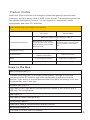
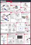
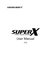
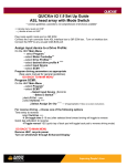
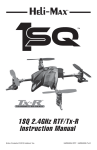
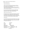
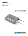
OPTIMUS
Economical Flight Controller
Brief U ser M anual(V1.0)
Content
-1-
Warning & Disclaimer
Multi-rotors Flight Controller is an excellent autopilot system. Although we
do our best to let the controller in the safest state when there is power input, for
example: signal is prohibited sending from the motors to the ESCs, in the process
of system calibration and parameters setup, we still strongly recommend
customers to remove all propellers, and use UBEC to supply power to the FC and
keep children away . We assume no liability for damage(s) or injuries incurred
directly or indirectly from the use of this product.
-2-
Product Profile
Multi-rotor flight controller is an autopilot system designed for aircraft model
hobbyists, which is mainly used on multi-rotors aircraft. The autopilot system has
the attitude stabilization function . It is very popular in amusement, aerial
photography and other FPV activities.
QUAD-ROTOR Flight Controller Control Modes
Atti. Mode
Manual Mode
Maximum rudder angular velocity is 180°/s
Command Stick Meaning
Multi attitude control; Stick
center position for 0˚ attitude,
Stick endpoint is 35˚attitude.
No height lock.
YES
Command Linearity
Stick Released
Safety
Maneuverability
Maximum pitch and roll angular
velocity is 220°/s, No height
lock.
No position holding, only
attitude stabilization
NOT Recommend
Low voltage protection
Depends on experience.
High agility, high stability
High agility
Items in the Box
Main Controller (MC) ×1
The Main Controller (MC) is the brain of the system. Through it, ESCs are
connected to the RC receiver and other equipments to achieve autopilot
function. It has a built-in Inertial Measurement Unit (IMU) containing one 3-axis
accelerometer, one 3-axis gyro.
Versatile Unit (VU) ×1
It includes a LED light which indicates different states of the aircraft and a
USB port for configuration.
USB Cable ×1
This cable is used to configure MC.
3-PIN Servo Cable ×7
Cables are used to connect the MC and the receiver
3M Gummed Paper ×6
It is used to fix MC and VU module
-3-
Notice
1.Please disconnect ESCs with battery or remove all propellers during the
configuration !
2. Don’t put the MC upside-down. The output ports of MC(Direction of the arrow)
should point to the front of multi-rotor.
3. You have to restart the MC and calibrate the Tx again when you
change the RC system.
4. In the process of Tx Calibration :
Throttle: Slide left is craft down, slide right is craft up;
Rudder: Slide left is nose left, slide right is nose right;
Elevator: Slide left is craft back, slide right is craft front;
Aileron: Slide left is craft left, slide right is craft right.
5.Before flying, make sure switch on the transmitter firstly, then power on
multi-rotor. After landing, power off multi-rotor firstly, and then switch
off the transmitter!
6.If you turn on the gimbals control during the configuration, there will be
output from X1 and X2 ports. Now you should not connect these ports to
ESC which is equipped with propellers and motors.
7.During the flight, throttle stick position should be always higher than
10% t ravel .
8.Low voltage protection is NOT for fun! You should land your multi-rotor
ASAP in any case in order to avoid crash and other damages.
9.By using Immediately mode to stop motors, in any control mode, motors
will stop immediately when throttle stick is under 10% . In this case, if you
push the throttle stick over 10% in 5 seconds after motors stop, motors
will re-start; Combination Stick Command (CSC) is not needed to restart notors.
If you don’t push throttle stick over 10% after motors start in 5 seconds,
motors will stop automatically.
10.Red light blinking indicates battery voltage is low, please land ASAP.
11.Do NOT move any command sticks and the aircraft during system initialization and selfcheck!
-4-
Assembly
Mc
please use 3M gummed paper provided to mount MC. The output
ports of MC(Direction of the arrow) should point to the front of multirotor. You’d better put MC at the gravity center of multi-rotor.
Please make sure all ports are accessible when installing the MC so as to
facilitate connecting wires and software configuration.
in 3-pin ports. pins near the nicks are signal pins.
After choosing a location to mount the MC, it is recommend that you Do
NOT mount the MC until all wires are connected and software
configurations are completed.
FUTABA/HITIC
RECEIVER
1
2
3
4
To ESC motor
7
AUX2
JR
RECEIVER
RUDD
M5、M6 or to Gimbal
ELEV
AILE
THRO
To Battery
R/C system
These are example connections. Please setup
Airleron,Elevator,Throttle,Rudder channels on Tx first, and choose
one 2 positions switch / channel as control mode switch, then connect
your receiver to the right ports on MC.
LED
2S-4S
VU
Do not mount it on any other electronic devices. Make sure you can see
the LED light during flying. LED indicator is 4-pin wire,E5 port is 3-pin
wire.
Assistant Software Installation
In order to make it easier for users to install the configuration software and
simplify the operation, we made the installation package, just copy the files in the
CD into the computer, then click the file installation and implement it.
Compatible computer’s system: XP, Win 7(32 bit). If you Win7( 64 bit) system,
please press “F8" function key when you start the system,then will pop up a start list,
select”do not start using number certificated sign”, then the software
can work normally.
-5-
MOTOR STARTUP:
In case of false operation of the throttle sticks, please start the aircraft by using the two unlock
way.
Move the sticks as shown on the image, execute any one way will start motors. After executing this
procedure, You have to push the throttle stick in five seconds , otherwise the motors will stop
running and you have to repeat the procedure. After the motor stop running , if you directly push
the throttle stick in five seconds ,motor will work again and unlocking operation is not needed to execute .
Do not execute these unlock procedure during flying in case of causing false operation.
Trim compensation:
Each flight controller is calibrated and tested before sending out. But sometimes there may be an
error during the aircraft mechanical components installation or the FC is not in an absolute
horizontal position when installed , and this can cause the airplane a small drift during flying .So
Drift compensation function is opened for this case and it the drift phenomenon can be modified
within a certain range.
Operation method (when there is a drift phenomenon during flying):
Land the aircraft , keep the throttle stick at the lowest position more than 5 seconds (throttle
control is in the locked state, the motor will not work if you push the throttle stick at this time). Push
the throttle stick to the highest point then enter into the calibration mode as shown in figure 2.
2.At this time, the stick which control the aircraft's front and back, right and left is used as
“functional” sticks. If the aircraft is drifting to front during flying, move the elevator stick back to the
stick’s biggest travel( each push is a unit volume for modification, if modification is not enough,
push a few times). If the aircraft is drifting to back then push the elevator stick front to modify. The
modification for the aircraft’s right and left drift is the same reason.
If the aircraft is drifting to left during flying, move the aileron stick right to the stick’s biggest travel(
each push is a unit volume for modification, if modification is not enough, push a few times). If the
aircraft is drifting to right then push the aileron stick left to modify.
Finally, push the “functional “ stick in the center position and also make the throttle stick return to
the lowest point.
3. Unlock the transmitter , start the motors and test whether the drift is improved or not . If not ,
please repeat step 1 ,2 procedure above.
ELEV(俯仰)
THRO(油门)
RUDD
(方向舵)
RUDD
(方向舵)
AILE
(横滚)
THRO(油门)
THRO(油门)
AILE
(横滚)
ELEV(俯仰)
Picture1
Picture2
-6-
SOFTWARE PROCESS
Introduction of the function buttons of the main interface
Meaning of the
red marked numbers above:
1. It means to import the flight control parameters saved last time from the
file, including the calibration parameter of the radio. If the radio is not
replaced and neutral position has not changed, there is no need to
calibrate again. Parameters will be input and written into the flight
controller
2 . Output parameters: Save all the parameters of the current flight controller
to a file in order to be convenient to write into the flight controller next
time.
3. Read the current flight controller parameters. It can be used only when
flight controller is successfully connected.
4. Write the changed parameters into flight controller. It can be used only
when flight controller is successfully connected.
5. It is the parameter setting interface of current selected function.
6. Display interface of the flight controller’s current state:
.Red light blink : The flight controller is not connected to the computer.
.Yellow light blink: Signal transmission. Green light blink: The flight
controller is successfully connected.
7.Display area of language choose, minimize button and close button.
8.Function selection area: display or set the parameters as needed.
9.Image display area.
10.Current place of mouse, it is the description of the related functions.
-7-
Motor Setting
1.Set the aircraft’s type. There is mainly four aircraft’s type, Default is Quad copter X. If
choose other types, click the appropriate type button and then click”Write”. (Red number 4
of the interface button) . If you select the hexacopter type, X1 is for M5 and X2 is for
M6. Please connect the motor according to the instruction and see the motor’s
rotating direction is right or not, if not , switch any of two wire connections of the incorrect motor
to change it’s rotation direction.
M2
M1
Front
M1
M6
M2
Front
Front
Front
M2
M2
M1
M1
M6
M3
M4
M3
M4
M5
M3
M3
M4
M4
M5
2.ESC type select. There are mainly two types of ESC- 500 Hz high speed ESC and
400hz normal speed ESC, click “write” and write it into the flight controller after
choosing.
It is prohibited to use 500Hz ESC after you choose 400Hz ESC type in Motor Setting procedure.
It can cause damages because the motors will spin at a high speed .
3.Idle speed setting: Set the speed of the motor rotation after unlocking.
Default is 20% of the throttle whole travel. It can also be changed according to your needs.
Highest is 30% of the throttle whole travel.
4.Set the time to stop motors. That is, motors can rotate how long when the throttle
stick is at the lowest point. From left to right, the rotating time increases by degrees. On
the rightmost side, motor keeps spinning and can only stop by the radio.
-8-
Tx calibrate
1. Calibration of Tx ,channel data Reverse and Normal, four channels direction
principles are as follows:
Throttle: Slide left is craft down, slide right is craft up
Rudder: Slide left is nose left, slide right is nose right
Elevator: Slide left is craft back, slide right is craft front.
Aileron: Slide left is craft left, slide right is craft right
Tx calibration procedure:
Click START button, move the radio’s four channel individually to the
highest and lowest point, after do that, the other three channels sliders
should be in the middle except T. Confirm the channel data direction
according to the show situation, and then click the End button. Then push
the throttle stick, see if the slider’s move is following these principles, if
not, click the normal button on the right, then the button will be changed
as Reversed, push the stick again and see if the direction is same as the
above principles. Test each channel like this.
2. Monitor Auxiliary channel E1.
3. Display the flight mode of current flight controller.
4. Set throttle curve parameters and the corresponding curve, write
individually numbers in the two texts ( range 0-100 ) Select the needed
curve according to the curve shown on the left,After finishing setting, it
i s n eeded to click”Write” button to write the data into the controller.
-9-
Autopilot:
1.Adjustment of flight controller’s gyroscope sensitivity and flexibility. Sensitivity of Roll and
pitch can be changed via the auxiliary channel E1, you can also choose “cancel” and use
manual input. Input the Yaw gain by hand according to the needs, manual input
range(0~255). Flexibility of Roll and pitch can be adjusted via the auxiliary channel E1, you
can also choose “cancel” and use manual input, manual input range(0~255). If need to set
as default values, click the default button.
2.Trim: The two text display is the current flight controller’s value fine-tuning in the roll and
pitch directions. Reason of setting the offset : when flight controller is in attitude mode, there is
no input in the throttle’s roll and pitch channel. At this time, the aircraft will be obviously
towards one direction, then you can set the aircraft‘s offset in that direction according to the
situation of the aircraft .For example: In the case of no input in any radios’ channels
exluding the throttle channel, while the plane is toward front , so in order to correct this offset,
it needs to add a fine-tuning value. Ensure flight controller is not turned on and push the throttle
stick to the highest point , then push the stick controlling the aricraft’s pitch back (opposite to
the aircraft’s Offset direction) to the highest point . Monitor this values’ change on the
software, ( increase per 1 shows per 0.1 increase). The method of setting the offset in other
three drections is the same. Offset adjustment can be currently made in the flying field , and
judge the setting value is appropriate or not according to the plane’s real-time state.
That’s the Drift compensation as introduced before.
3.PID Setting
If you don’t understand the meaning of PID, it is prohibited to change the default
parameter. If changed and the effect is not good, please click the PID default button. If you
want to change the PID value, it needs to click the PID setting button. .All the changes
above need to click the Write button to input the changed content.
-10-
Voltage Monitor
1.Show the current voltage of the flight controller(For reference only)
2.Set the protecting voltage value, default is for reference. It can be set according to the
situation. Notice: The second level protecting voltage should not be set too low, otherwise
can be easy to cause crash .
-11-
PTZ Control
1.Button of PTZ control: default is “ turn off”. When turn on the button,
choose the related frequency of the servo. E1 is for controlling the PIZ’s pitch. The
aircraft’s roll will be self-balance based on the flight cotroller’s situation.
2.Set the two servo’s min, mid, max value.
3.Sensitivity of the camera mount: Set the parameter according to the real effect of the gimbals.
Revised direction button: choose “Normal" or “Reverse" based on the camera mount's balance
state. All the changes above need to click the Write button to input the changed
content.
Notice: X1,X2 is the port for gimble control( when the aircraft is quad-rotors). If it’s hexacopter,
there will be no gimble control function and X1 is for M5, and X2 is for M6.
-12-
APPENDIX 1
Port Description
Main Controller
For roll control(left/right)
For pitch contro(front/back)
For throttle control
For rudder control
For control mode switch
For gimbalcontrol
Main Controller
Not available
Not available
Not available
For monitoring voltage(connecting the Versatile Unit)
To # 1 motor
To # 2 motor
To # 3 motor
To # 4 motor
To # 5 motor/gimbal pitch control
To # 6 motor/gimbal roll control
LED port,for LED wire connection from Versatile Unit
Expansion port ,for future upgrade and usage
Versatile Unit
V-SEN
V-sen port:to MC E5 port,for monitoring battery voltage。
LED
LED wire,to MC LED port
Micro-USBport:PC connection for configuration and firmware
upgrades.
-13-
APPENDIX 2
LED Description:
Self-check
Self- check
finish
LED blinking indifications
LONG Green light blinking
Atti.Mode
Green light blinking
Manual Mode
Red light blinks slowly, First
level voltage protection warm
Red light blinks quickly, second
level voltage protection warm
Long red light blinking.
Show Error
Reasons of the Error:
1. The transmitter’s signal is not detected, please check the transmitter’s
switch is on or off ,also check the frequency of the trasmitter and receiver to
make sure it is same . All wires connection needs to be checked as well.
2.Tx calibration is false and please calibrate it again.
-14-
APPENDIX3
Specifications
Built-in Function
1. Attitude mode and manul mode Autopilot
2. Low voltage Protection
Peripheral
Supported Multi-rotors:
Supported ESC Output:
Transmitter requirement:
quadcopter , hexacopter
400Hz normal ESC and 500Hz high speed ESC
PCM or2.4GHz with minimum 4 channels
Assistant Software System Requirement:windows XP , Windows7
Electrical and Mechanical
Working Voltage Range: 1 .MC:4 .8 ~5 .5V
2. VU:7.2V~14.8V(2S~4S LiPo)
Power Consumption:1.25W,(0.25A/5V)
Operating temperature:-10℃ ~ 50℃
Weight: MC:25.5g,VU:9g
Dimension:MC 43mm×36.5mm×18mm
-15-