1
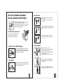
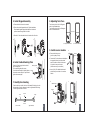
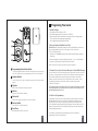
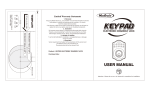
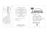
35
1-9/16" 1-3/8"
40
Fit here on door edge
45
Mark Ø1" (25.4mm) hole at
center of door edge.
2" 1-3/4"
51
ELECTRONIC DEADB OLT LOCK
2
3
4
5
6
7
8
9
0
FOR BACKSET 60mm (2-3/8”)
Ø54mm (2-1/8")
1325 S. Colorado Blvd. Suite 400 Denver, CO 80222
(877) 254-5625
USER MANUAL
LockState
1
FOR BACKSET 70mm (2-3/4”)
WI-FI
TEMPLATE
®
WI-FI ELECTRONIC DEADBOLT
INSTALLATION INSTRUCTIONS
3. Install Latch
a. Insert the latch and ensure it is paralleled to
the door face.
Mark the outline of the faceplate, then take
out the latch.
The BACKSET is the distance between the center of
cross bore and edge bore of the door.
Adjustable latch fits both BACKSET of 2-3/8” (60mm)
and 2-3/4” (70mm). Please follow the steps shown
below for BACKSET adjustment.
b. Chisel 1/8” (3mm) deep along the outline to
allow the faceplate to be aligned with the door
edge.
Latch Backset Adjustment :
Rotate the latch case as diagram on the
right for backset 2-3/4" (70mm) or
reverse direction for 2-3/8" (60mm).
c. Insert the latch and tighten it with screws.
Note : please use tapping screws for metal
door.
m)
0m
" (7
3/4
2-
4. Install Strike
1. Mark The Door With Template
a. To identify the center of strike :
close the door, on the basis of the faceplate
mark horizontal center line of strike.
Ensure the center of faceplate and the center
of strike are aligned.
Use the mark as a guide outlines the strike.
Select the height and backset as desired on the
door face ; use the TEMPLATE as an indication
to mark the center of the circle on the door face
and the center of the door edge.
b. Chisel 5/64” (2mm) deep along the strike
outline to allow the strike to be aligned with
the doorframe.
2. Drill Holes
Using the marks as a guide to drill a hole Ø2-1/8”
(54mm) through the door face for the lockset, then
a hole of Ø1” (25.4mm) for latch.
c. Insert the strike and tighten it with screws.
Note : please use ”tapping screws” for metal
door.
1
2
5. Install Keypad Assembly
8. Adjusting Turn Piece
a. Ensure the latch bolt must be retracted.
Turn the turn piece to left for 45 degrees
when it's right-handed door.
Turn the turn piece to right for 45 degrees
when it's left handed door.
b. Please refer to the diagram below for Cylinder Installation.
Place deadbolt against keypad with tailpiece in horizontal
position inserted through hub of the latch.
Turn Piece
c. Pass the IC wire under the latch to the interior side of the door.
a
c
b
(For Right Handed door)
9. Install receiver module
Cylinder
Battery
Cover
b. Connect the IC wire and ensure the tailpiece
is engaged with turn piece, then attach
receiver module to the door with screws.
It's optional to use wood screws.
(Wood screws only for wood door)
6. Install Inside Mounting Plate
Pass the IC wire through the wire hole of
the mounting plate.
Fix the mounting plate with screws.
If outside lock assembly is lopsided, please
loosen the screws to adjust it's position and
tighten the screws again.
a
a. Remove the battery cover
(push it up and pull it out).
IC wire
(For Left Handed door)
Mounting Plate
c. Insert 4 (AA) 1.5V alkaline batteries and
put the battery cover back to the receiver
module.
Screws
IC wire
b
7. Identify Door Handing
Face the door from outside, the door is left handed if the hinge is on the
left-hand side of the door, whereas the door is right handed if the hinge
is on the right-hand side of the door.
Interior
Wood Screws
c
Screws
Hinge
Door
Exterior
(Left Handed)
(Right Handed)
3
4
Programing Your Lock
1.Default Settings
1. The default User Code on the lock is 1234
2. The default Programing Code (PC) on the lock is 12345678
3. Please change both of these codes when first setting up the lock for security purposes.
This can either be done through keypad programming
(refer to Keypad Programming Functions section).
2.Set Lock Handing (Deadbolt Lock Only)
IMPORTANT: Before programming anything else on your Deadbolt Lock, you must first
set the handing (whether your lock is on the right or left side of your door).
To do this, follow these steps:
1. Put your lock in the locked position with the deadbolt fully extended by turning the
thumb turn.
2. Enter the following on the keypad: [Programming Code] + 140 + LockState Button
3. You will see 2 green flashes and hear two beeps if successful
Note: For the lever lock, you do not need to perform this operation.
Programming Button/Enter Button
The Programming/Enter Button is utilized for unlocking the door after entering
user codes, clearing errors and programming the lock. It's also a lock button.
Number Buttons
Enter User Codes (4-10 digits in length) and program the lock via the number
buttons.
Cylinder
3.Connect Your Lock to the Internet& Login to Device Web Manager
Your lock has a built in Wi-Fi chip that allows you to program and control your lock from
the internet. Connecting your lock to the internet is required for remote operation and
other advanced features such as temporary guest codes, schedules, rules & alerts.
However, connection to the internet is not required for the lock to operate. In fact,
all programming enabled on the lock will continue to operate if your internet
connection is interrupted.
To connect your lock to the internet via your Wi-Fi router and to login to your online
Device Management account, please refer to the Internet Connection Setup Guide
provided separately with your lock.
Lock or unlock the latch bolt by key from exterior.
Washer
Protects the lock from water damage.
4. Initial Lock Programming
Battery Lid
Programming your lock can either be done through your online account on the Device
Web Management portal (refer to the Internet Connection Setup Guide) or on the
keypad of the lock. Several of the programming functions that are available online
are not available via Keypad Programming (creating guest codes, schedules, alerts, etc.).
However, common functions such as adding or deleting User Codes can also be done
through Keypad Programming.
Slide the lid to change the batteries or access reset button.
Battery Holder
Uses Four AA (1.5V) Alkaline batteries.
Turn-Piece
Retract/Extend the latch bolt from door.
5
For instructions on programming via your keypad, please refer to the Keyad
Programming Functions in the next section.
6
Keypad Programming Functions
Enable all user code
Enter PC
Auto-detect lock handing (Deadbolt Lock Only)
Enter PC
Mute Keypad
140
Note : If you have a lever lock you do not need to run this operation. For deadbolt
locks, please run the door-handing identifying before doing anything else on
your lock. Put your lock in the LOCKED position before running this function.
Change program code
Enter PC
100
110
new PC
User code
Enter PC
000
001
Note: If your router supports it (newer models usually do), WPS (WiFi Protected Setup)
is a simple and secured way to connect a device to an existing network.After
entering the keypad function for WPS, you will see 2 green beeps. Within 10
seconds, the lock will begin to flash green and beep for up to 2 minutes.
Once you enable WPS on the lock, press the WPS button on your router to
make the link. Refer to your routers manual for further instructions on WPS.
User code
Check Online Connection Status
131
Note: You will not be able to unlock the door from the keypad or through your online
account if no codes exist in the lock. You will have to add a new code to unlock
your door from the keypad or online.
Disable all user code
Enter PC
161
WPS
Delete all user code
Enter PC
Un-mute Keypad
Enter PC
Delete single user code
120
160
Reset Wi-Fi connection
Note : Up to 250 sets of User Code can be saved. User Code should be 4-10
digits in length.
Enter PC
Enter PC
Enter PC
Add user code
Enter PC
151
Enter PC
005
Note: If your lock is successfully connected to the internet, you will see 2 green flashes
with 2 beeps. If not connected successfully, you will see 2 green flashes followed
by 3 red flashes and beeps. If this occurs, reset your Wi-Fi connection go through
the connection process again.
150
Note: This function will provide privacy if you want to ensure no active codes can unlock
the door. This will not delete codes, just make them inactive until you enable
them again (below).
7
8
Detailed Lock Functionality
6. User Code
1.Battery
Four AA(1.5V)Alkaline batteries.
2.Low Battery
1. The batteries should be changed immediately once you see the LED flashes in red and
hear 6 beeps when press the LockState button.
2. All settings are retained in the memory and will not be affected even if the battery is
completely dead.
3. The lock still can be operated by key even there is a power outage.
3. LED Indicator
1. LED flashes green once when successful operation.
2. LED flashes green once when successful programming.
3. LED flashes red 3 times when there is an operation error.
4. LED flashes green1 times when system has been restored to default setting.
5. LED flashes red 6 times if battery power is low.
1. The preset User Code is 1234. Please delete it and create your personal code when first
time operation. This can be done on the keypad (refer to Keypad Programming
Functions section) or from your online account on the Device Web Manager.
2. Up to 250 sets of User Codes can be saved.
3. User Codes are only used for unlocking the lock, without programming function.
4. User Codes can be 4-10 digits in length.
5. User Code can be deleted or changed anytime if needed.
7. Delete Individual User Code
1. User Codes can be deleted individually. You can reset the same User Code even it was
deleted before.
2. User Codes can either be deleted on the keypad (refer to Keypad Programming
Functions Section) or from your online account on the Device Web Manager.
8. Delete All User Codes At Once
1. All the User Codes can be deleted at once. You can still reset the same User Codes even
they were deleted before.
2. Auto-locking and Keypad locking function will be invalid after deleting all User Codes and
the lock can only be operated by key. All the electrical functions will be restored when
recreate new User Codes.
6. To be able to unlock the door again, you will need to create new User Codes.
This can be done on the keypad (refer to Keypad Programming Functions section)
or from your online account on the Device Web Manager.
4. Audio Indicator
1.
2.
3.
4.
5.
1 beep sound indicates a successful operation
1 beep sound indicates a successful programming.
3 beeps indicate an operation error (with red light).
1 beep soundindicate that system has been restored to default setting.
5 beeps when codes input error, the operation will stop for system protection.
(Refer to 17)
6. 6 beeps indicate the power of battery is low.
9. Temporarily Disable All User Codes
5. Programming Code
1. The preset Programming Code is 12345678. Please change this to your own code when
first time operation. This can be done on the keypad (refer to Keypad Programming
Functions Section) or from your online account on the Device Web Manager.
2. There is only one Programming Code for function setting.
3. Programming Code is only for function setting, you can't unlock the door by pressing
Programming Code.
4. Programming code has to be 8 digits in length.
5. Programming code can be changed anytime if needed.
1. From the keypad only, you can choose to temporarily disable all active User Codes on
the lock. This is meant to be a privacy function. This does not delete the User Codes,
but just disables them until you enable them again.
2. Please refer to the Keypad Programming Functions section for instructions on temporarily
disabling and enabling User Codes.
10. Reset Wi-Fi Connection
1. You can reset Wi-Fi connection on your lock if needed. This would likely be needed if
you purchase a new router and need to enter the new SSID and password for your new
router into your lock.
2. Follow the Internet Connection Setup Guide provided with your lock.
11. Unlocking the door
9
1. The door can be unlocked by key, entering a valid User Code on keypad from outside,
by interior turn-piece, or from your online account.
2. To unlock the door on the keypad, enter the User Code and then press the
LockState/Enter button.
10
12. Lock the door
The door will be locked by key, pressing the LockState/Enter button on the keypad from
outside, by interior turn-piece, or from your online account.
13. Incomplete Door Closing / Opening
1. If the latch bolt is not extending/retracting completely when you try to lock/unlock the
door via the keypad, you will see the LED flash red 3 times and hear 3 beeps (No alarm
when it's in mute). The lock will reverse itself automatically in this case to the position
it started in.
2. If the latch bolt gets stuck or can't extend/retract completely all the time, please check
if the strike aligns with the latch bolt perfectly and adjust the strike to proper position.
After long use of the door hinge, the latch bolt might get stuck easily because the door
may have warped or shifted.
14. To Activate / Deactivate Auto-Locking Function
1. This function is for the lever lock only. When enabled, the door will automatically lock
itself within 10seconds after unlocking.
2. This function is not enabled by default. You will have to enable it.
3. This function can only be enabled from your online account on the Device Web Manager.
15. Toggle Mute On/Off
1. By default, you will hear beep sounds when pressing the keypad, programming or
operating errors. This can be turned off if needed.
2. LED Illumination still functions when it's in mute.
3. Motor operating sound cannot be muted.
Simple Troubleshooting
Situation 1 (Deadbolt Lock Only)
After the installation of the deadbolt lock and batteries, pressing the
LockState button unlocks the door, and entering a User Code plus the
LockState button locks the door (the opposite of what you would expect).
Causes : The door-handing identifying process is not yet complete.
Solutions : Please execute the door-handing identifying process as soon as the
installation of the lockset is completed.
Situation 2
After the installation of the lockset and batteries, no responses
when you press any button (no sounds are emitted, and the
back light does not work).
Causes : It could be a problem caused by incorrect battery insertion or the improper
connection ofthe cable.
Solutions : Check to see if the battery polarities have been reversed or if the battery is
dead. If so, please re-install or change the battery. If not, please check if
the cable is appropriately connected.
Situation 3
The lock is not showing up in my online account as connected to the
internet.
16. Code Protection Function (Lockout)
Operation will be disabled if entering unauthorized codes over 5 times. The System will
re-operate again after 30 sec.
17. Illumination
The LED Keypad will light up when pressing any button for ease of operation in the dark.
Remarks
1. We recommend using alkaline battery in order to stabilize the power supply.
2. Do not mix alkaline batteries with regular zinc-carbon ones or mixed brands.
3. Do not use any chemical liquid or lubricating oil with additives to clean the lock body,
it will damage the surface or even mainboard.
11
Causes : It could be that the incorrect router password was entered during the internet
connection process. Another possibility is that your router is offline and needs
to be reset.
Solutions : Enter the keypad programming function for resetting Wi-Fi connection.
This is [Enter PC] + 0 0 0 + [LockState Button].
Situation 4
Locking and unlocking from the keypad only works when the key is in
the key cylinder.
Causes : The spindle that goes through the latch was installed in the wrong position.
Solutions : Make sure to install the lock with the key OUT of the cylinder. Also make
sure that the spindle is in the horizontal position when threading through
the latch.
12