1
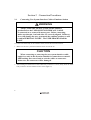
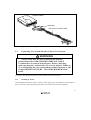
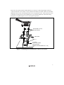
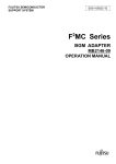
To our customers, Old Company Name in Catalogs and Other Documents On April 1st, 2010, NEC Electronics Corporation merged with Renesas Technology Corporation, and Renesas Electronics Corporation took over all the business of both companies. Therefore, although the old company name remains in this document, it is a valid Renesas Electronics document. We appreciate your understanding. Renesas Electronics website: http://www.renesas.com April 1st, 2010 Renesas Electronics Corporation Issued by: Renesas Electronics Corporation (http://www.renesas.com) Send any inquiries to http://www.renesas.com/inquiry. Notice 1. 2. 3. 4. 5. 6. 7. All information included in this document is current as of the date this document is issued. Such information, however, is subject to change without any prior notice. Before purchasing or using any Renesas Electronics products listed herein, please confirm the latest product information with a Renesas Electronics sales office. Also, please pay regular and careful attention to additional and different information to be disclosed by Renesas Electronics such as that disclosed through our website. Renesas Electronics does not assume any liability for infringement of patents, copyrights, or other intellectual property rights of third parties by or arising from the use of Renesas Electronics products or technical information described in this document. No license, express, implied or otherwise, is granted hereby under any patents, copyrights or other intellectual property rights of Renesas Electronics or others. You should not alter, modify, copy, or otherwise misappropriate any Renesas Electronics product, whether in whole or in part. Descriptions of circuits, software and other related information in this document are provided only to illustrate the operation of semiconductor products and application examples. You are fully responsible for the incorporation of these circuits, software, and information in the design of your equipment. Renesas Electronics assumes no responsibility for any losses incurred by you or third parties arising from the use of these circuits, software, or information. When exporting the products or technology described in this document, you should comply with the applicable export control laws and regulations and follow the procedures required by such laws and regulations. You should not use Renesas Electronics products or the technology described in this document for any purpose relating to military applications or use by the military, including but not limited to the development of weapons of mass destruction. Renesas Electronics products and technology may not be used for or incorporated into any products or systems whose manufacture, use, or sale is prohibited under any applicable domestic or foreign laws or regulations. Renesas Electronics has used reasonable care in preparing the information included in this document, but Renesas Electronics does not warrant that such information is error free. Renesas Electronics assumes no liability whatsoever for any damages incurred by you resulting from errors in or omissions from the information included herein. Renesas Electronics products are classified according to the following three quality grades: “Standard”, “High Quality”, and “Specific”. The recommended applications for each Renesas Electronics product depends on the product’s quality grade, as indicated below. You must check the quality grade of each Renesas Electronics product before using it in a particular application. You may not use any Renesas Electronics product for any application categorized as “Specific” without the prior written consent of Renesas Electronics. Further, you may not use any Renesas Electronics product for any application for which it is not intended without the prior written consent of Renesas Electronics. Renesas Electronics shall not be in any way liable for any damages or losses incurred by you or third parties arising from the use of any Renesas Electronics product for an application categorized as “Specific” or for which the product is not intended where you have failed to obtain the prior written consent of Renesas Electronics. The quality grade of each Renesas Electronics product is “Standard” unless otherwise expressly specified in a Renesas Electronics data sheets or data books, etc. “Standard”: 8. 9. 10. 11. 12. Computers; office equipment; communications equipment; test and measurement equipment; audio and visual equipment; home electronic appliances; machine tools; personal electronic equipment; and industrial robots. “High Quality”: Transportation equipment (automobiles, trains, ships, etc.); traffic control systems; anti-disaster systems; anticrime systems; safety equipment; and medical equipment not specifically designed for life support. “Specific”: Aircraft; aerospace equipment; submersible repeaters; nuclear reactor control systems; medical equipment or systems for life support (e.g. artificial life support devices or systems), surgical implantations, or healthcare intervention (e.g. excision, etc.), and any other applications or purposes that pose a direct threat to human life. You should use the Renesas Electronics products described in this document within the range specified by Renesas Electronics, especially with respect to the maximum rating, operating supply voltage range, movement power voltage range, heat radiation characteristics, installation and other product characteristics. Renesas Electronics shall have no liability for malfunctions or damages arising out of the use of Renesas Electronics products beyond such specified ranges. Although Renesas Electronics endeavors to improve the quality and reliability of its products, semiconductor products have specific characteristics such as the occurrence of failure at a certain rate and malfunctions under certain use conditions. Further, Renesas Electronics products are not subject to radiation resistance design. Please be sure to implement safety measures to guard them against the possibility of physical injury, and injury or damage caused by fire in the event of the failure of a Renesas Electronics product, such as safety design for hardware and software including but not limited to redundancy, fire control and malfunction prevention, appropriate treatment for aging degradation or any other appropriate measures. Because the evaluation of microcomputer software alone is very difficult, please evaluate the safety of the final products or system manufactured by you. Please contact a Renesas Electronics sales office for details as to environmental matters such as the environmental compatibility of each Renesas Electronics product. Please use Renesas Electronics products in compliance with all applicable laws and regulations that regulate the inclusion or use of controlled substances, including without limitation, the EU RoHS Directive. Renesas Electronics assumes no liability for damages or losses occurring as a result of your noncompliance with applicable laws and regulations. This document may not be reproduced or duplicated, in any form, in whole or in part, without prior written consent of Renesas Electronics. Please contact a Renesas Electronics sales office if you have any questions regarding the information contained in this document or Renesas Electronics products, or if you have any other inquiries. (Note 1) “Renesas Electronics” as used in this document means Renesas Electronics Corporation and also includes its majorityowned subsidiaries. (Note 2) “Renesas Electronics product(s)” means any product developed or manufactured by or for Renesas Electronics. User’s Manual H8S/2633 Series TQFP-120 User System Interface Cable (HS2633ECN61H) for E6000 Emulator User’s Manual Cautions 1. Renesas neither warrants nor grants licenses of any rights of Renesas’s or any third party’s patent, copyright, trademark, or other intellectual property rights for information contained in this document. Renesas bears no responsibility for problems that may arise with third party’s rights, including intellectual property rights, in connection with use of the information contained in this document. 2. Products and product specifications may be subject to change without notice. Confirm that you have received the latest product standards or specifications before final design, purchase or use. 3. Renesas makes every attempt to ensure that its products are of high quality and reliability. However, contact Renesas’s sales office before using the product in an application that demands especially high quality and reliability or where its failure or malfunction may directly threaten human life or cause risk of bodily injury, such as aerospace, aeronautics, nuclear power, combustion control, transportation, traffic, safety equipment or medical equipment for life support. 4. Design your application so that the product is used within the ranges guaranteed by Renesas particularly for maximum rating, operating supply voltage range, heat radiation characteristics, installation conditions and other characteristics. Renesas bears no responsibility for failure or damage when used beyond the guaranteed ranges. Even within the guaranteed ranges, consider normally foreseeable failure rates or failure modes in semiconductor devices and employ systemic measures such as fail-safes, so that the equipment incorporating Renesas product does not cause bodily injury, fire or other consequential damage due to operation of the Renesas product. 5. This product is not designed to be radiation resistant. 6. No one is permitted to reproduce or duplicate, in any form, the whole or part of this document without written approval from Renesas. 7. Contact Renesas’s sales office for any questions regarding this document or Renesas semiconductor products. Preface Thank you for purchasing this user system interface cable (HS2633ECN61H) for the Renesas’s original microcomputer H8S/2633 series. The HS2633ECN61H is a user system interface cable that connects an H8S/2633 series E6000 emulator (HS2633EPI61H; hereinafter referred to as the emulator) to the IC socket for a TQFP-120 package (package code: TFP-120) for the H8S/2633 series MCU on the user system. i Contents Section 1 Configuration....................................................................................1 Section 2 Connection Procedures ......................................................................4 2.1 2.2 2.3 2.4 2.5 Connecting User System Interface Cable to Emulator Station ......................................... 4 Connecting User System Interface Cable to User System ................................................ 5 2.2.1 Installing IC Socket ............................................................................................. 5 2.2.2 Soldering IC Socket ............................................................................................. 6 2.2.3 Inserting Cable Head ........................................................................................... 6 2.2.4 Fastening Cable Head .......................................................................................... 6 2.2.5 Connecting Cable Body to Cable Head ............................................................... 8 Recommended Dimensions for User System Mount Pad ................................................. 9 Dimensions for User System Interface Cable Head.......................................................... 10 Resulting Dimensions after Connecting User System Interface Cable ............................. 11 Section 3 Installing the MCU to the User System.............................................12 Section 4 Verifying Operation...........................................................................14 Section 5 Notice ................................................................................................15 ii Section 1 Configuration CAUTION Use an IC149-120-043-B5 socket (manufactured by YAMAICHI ELECTRONICS Co., Ltd.) for the TFP-120 package IC socket on the user system. Figure 1 shows the configuration of the HS2633ECN61H user system interface cable for the TFP-120 package. 1 To emulator station Cable body Screws (M2 x 12 mm) with flat washers (for fastening cable head) Screws (M2 x 8 mm) with flat washers Socket cover Cable head IC socket User system Figure 1 HS2633ECN61H User System Interface Cable 2 Table 1 lists the HS2633ECN61H components. Please make sure you have all of these components when unpacking. Table 1 HS2633ECN61H Components No. Component Quantity Remarks Includes flat cable 1 Cable body 1 2 Cable head 1 3 IC socket 1 For the TFP-120 package 4 Socket cover 1 For installing a TFP-120 packaged MCU 5 Screws (M2 x 12 mm) 4 For fastening cable head (with four flat washers) 6 Screws (M2 x 8 mm) 4 For installing a TFP-120 packaged MCU (with four flat washers) 7 Documentation 1 User’s manual for HS2633ECN61H (this manual) 3 Section 2 Connection Procedures 2.1 Connecting User System Interface Cable to Emulator Station WARNING Always switch OFF the user system and the emulator product before the USER SYSTEM INTERFACE CABLE is connected to or removed from any part. Before connecting, make sure that pin 1 on both sides are correctly aligned. Failure to do so will damage the user system and the emulator product or will result in PERSONAL INJURY. The USER PROGRAM will be LOST. To connect the cable body to the emulator station, follow the instructions below. 1. Make sure the user system and emulator station are turned off. CAUTION When connecting or removing the user system interface cable, apply force only in the direction suitable for connection or removal, while making sure not to bend or twist the cable or connectors. Otherwise, the connectors will be damaged. 2. After making sure the direction of the cable body connector is correct, firmly insert the cable body connector into the emulator station socket (figure 2). 4 0 0 0 6 E Emulator station Cable body User system interface cable Figure 2 Connecting User System Interface Cable to Emulator Station 2.2 Connecting User System Interface Cable to User System WARNING Always switch OFF the user system and the emulator product before the USER SYSTEM INTERFACE CABLE is connected to or removed from any part. Before connecting, make sure that pin 1 on both sides are correctly aligned. Failure to do so will damage the user system and the emulator product or will result in PERSONAL INJURY. The USER PROGRAM will be LOST. To connect the cable head to the user system, follow the instructions below. 2.2.1 Installing IC Socket After checking the location of pin 1 on the IC socket, apply epoxy resin adhesive to the bottom of the IC socket for a TFP-120 package, and fasten it to the user system before soldering. 5 2.2.2 Soldering IC Socket After fastening, solder the IC socket for a TFP-120 package to the user system. Be sure to completely solder the leads so that the solder slops gently over the leads and forms solder fillets. (Use slightly more solder than the MCU.) 2.2.3 Inserting Cable Head CAUTION Check the location of pin 1 before inserting. Align pin 1 on the IC socket for a TFP-120 package on the user system with pin 1 on the user system interface cable head, and insert the user system interface cable head into the IC socket on the user system, as shown in figure 3. 2.2.4 Fastening Cable Head CAUTION 1. Use a Phillips-type screwdriver whose head matches the screw head. 2. The tightening torque must be 0.098 N•m or less. If the applied torque cannot be accurately measured, stop tightening when the force required to turn the screw becomes significantly greater than that needed when first tightening. If a screw is tightened too much, the screw head may break or an IC socket contact error may be caused by a crack in the IC socket solder. 3. If the emulator does not operate correctly, cracks might have occurred in the solder. Check conduction with a tester and re-solder the IC socket if necessary. 6 Fasten the user system interface cable head to the IC socket for a TFP-120 package on the user system with the four screws (M2 x 12 mm; with four flat washers) provided. Each screw should be tightened a little at a time, alternating between screws on opposing corners. Take special care, such as manually securing the IC socket soldered area, to prevent the soldered IC socket from being damaged by overtightening the screws or twisting the components. Screws (M2 x 12 mm) with flat washers Cable head Pin 1 IC socket (IC149-120-043-B5 manufactured by YAMAICHI ELECTRONICS Co., Ltd.) User system Figure 3 Connecting User System Interface Cable to User System 7 2.2.5 Connecting Cable Body to Cable Head Connect the cable body to the cable head. Cable body Removing Push the remove jig Remove jig Cable head User system Figure 4 Fastening Cable Body 8 2.3 Recommended Dimensions for User System Mount Pad Figure 5 shows the recommended dimensions for the mount pad (footprint) for the user system with an IC socket for a TFP-120 package (IC149-120-043-B5: manufactured by YAMAICHI ELECTRONICS Co., Ltd.). Note that the dimensions in figure 5 are somewhat different from those of the actual chip's mount pad. 17.10 (min.) 13.80 (max.) 0.40 x 29 = 11.60 – 0.05 0.40 x 29 = 11.60 – 0.05 0.25 – 0.05 0.40 – 0.05 0.40 – 0.05 Unit: mm Figure 5 Recommended Dimensions for Mount Pad 9 2.4 Dimensions for User System Interface Cable Head The dimensions for the user system interface cable head are shown in figure 6. Unit: mm Tolerance: –0.5 mm Figure 6 Dimensions for User System Interface Cable Head 10 2.5 Resulting Dimensions after Connecting User System Interface Cable The resulting dimensions, after connecting the user system interface cable head to the user system, are shown in figure 7. Figure 7 Resulting Dimensions after Connecting User System Interface Cable 11 Section 3 Installing the MCU to the User System CAUTION 1. Check the location of pin 1 before inserting. 2. Use a Phillips-type screwdriver whose head matches the screw head. 3. The tightening torque must be 0.098 N•m or less. If the applied torque cannot be accurately measured, stop tightening when the force required to turn the screw becomes significantly greater than that needed when first tightening. If a screw is tightened too much, the screw head may break or an IC socket contact error may be caused by a crack in the IC socket solder. 4. If the MCU does not operate correctly, cracks might have occurred in the solder. Check conduction with a tester and re-solder the IC socket if necessary. Check the location of pin 1 before inserting the MCU into the IC socket on the user system, as shown in figure 8. After inserting the MCU, fasten the socket cover with the provided four screws (M2 x 8 mm; with four flat washers). Take special care, such as manually securing the IC socket soldered area, to prevent the IC socket from being damaged by overtightening the screws or twisting the components. 12 Screws (M2 x 8 mm) with flat washers Socket cover MCU Pin 1 IC socket (IC149-120-043-B5 manufactured by YAMAICHI ELECTRONICS Co., Ltd.) User system Figure 8 Installing MCU to User System 13 Section 4 Verifying Operation 1. When using the E6000 emulator for the H8S/2633 series, turn on the emulator according to the procedures described in the H8S Series E6000 Emulator User's Manual. 2. Verify the user system interface cable connections by accessing the external memory and ports to check the bus states of the pins with the MEMORY_FILL command (emulator command). If an error is detected, recheck the soldered IC socket and the location of pin 1. 3. The emulator connected to this user system interface cable supports two kinds of clock sources as the MCU clock: an emulator internal clock and an external clock on the user system. For details, refer to the H8S/2633 series E6000 Emulator Supplementary Information (HS2633EPI61HE). To use the emulator internal clock Select the clock in the emulator station as the system clock (φ), by using the CLOCK command (emulator command). To use the external clock on the user system Supply the external clock from the user system to the emulator. Connect a crystal oscillator to the EXTAL and XTAL terminals for the system clock (φ), and to the OSC1 and OSC2 terminals for the subclock. The user system interface cable has the oscillator circuits shown in figure 9. For details, refer to section 23, Clock Pulse Generator, in the H8S/2633 Series Hardware Manual. R1 1 M HCU04 HCU04 To E6000 emulator HCU04 R2 270 EXTAL XTAL Figure 9 Clock Oscillator Circuits 14 Section 5 Notice 1. Make sure that pin 1 on the user system IC socket is correctly aligned with pin 1 on the cable head before inserting the cable head into the user system IC socket. 2. The dimensions of the recommended mount pad for the user system IC socket are different from those of the MCU. 3. This user system interface cable is specifically designed for the HS2633EPI61H emulator. Do not use this cable with any other emulator station. 4. To prevent breaking of wires in the cable body, do not place heavy or sharp metal objects on the user system interface cable. 5. While the emulator station is connected to the user system with the user system interface cable, force must not be applied to the cable head. Place the emulator station, user system interface cable, and user system as shown in the example in figure 10. Emulator station Place components so that the cable body and cable head are parallel to the user system. Cable head is parallel to emulator station Cable head is parallel to user system User system Leave plenty of space so that force is not applied to cable head. Figure 10 User System Interface Cable Location Example 15 6. The P1 short connector is used for testing. Do not remove the short pin that is inserted in the sides of pin 1 and pin 2. 3 P1 1 Figure 11 P1 Short Connector 16