1
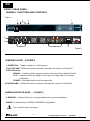
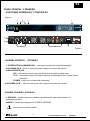
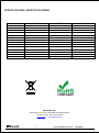
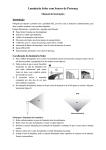
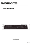
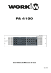
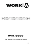
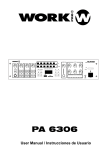
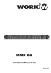
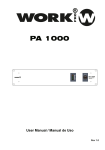
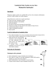
M SERIES
POWER
5
5
4
6
3
7
1
9
2
0
4
6
0
10
3
POWER
7
2
8
SIG
CLIP
10
CH A
CLIP
SIG
8
9
1
M 1400
PROFESSIONAL AMPLIFIER
CH B
User Manual / Manual de Uso
Rev 1.0
EN
SAFETY RELATED SYMBOLS
WARNING:
TO REDUCE THE RISK OF FIRE OR
ELECTRIC SHOCK, DO NOT EXPOSE
TO RAIN OR HUMIDITY.DO NOT
REMOVE COVER. THIS PRODUCT IS
NOT INTENDED FOR USE OTHER THAN
STATED.
GRAPHICAL SYMBOLS EXPLANATION
This symbol, wherever used,alerts you to
the presence of un-isulated and dangerous
voltages within the product enclosure.
These are voltages that may be sufficient to
constitute the risk of electric shock.
External Connection
Always use proper ready-made insulated mains
cabling (power cord). Failure to do so could result
in shock or fire. If in doubt, seek advice from a
registered electrician.
Do not Remove Any Cover
This symbol, wherever used, alerts you to
important operating and maintenance
instructions. Please read.
Protective Ground Terminal
AC mains (Alternating Current)
Within the product are areas where high voltages
may bepresent. To reduce the risk of electric shock
do not remove any covers unless the AC mains
power cord is removed.
Covers should be removed by qualified service
personnel only.
No user serviciable parts inside.
Hazardous Live Terminal
ON: Denotes the product is turned on.
OFF: Denotes the product is turned off.
WARNING
Describes precautions that should be observed to
prevent the possibility of death or injury to the user.
CAUTION
Fuse
To prevent fire an damage to the product, use only
the recommended fuse type as indicated in this
manual. Do not short-circuit the fuse holder.
Before replacing fuse, make sure that the product
is OFF and disconnected from the AC outlet.
Protective Ground
Describes precautions that should be observed to
prevent damage to the product.
WARNING
Before turning the product ON, make sure that it is
connected to Ground. This is to prevent the risk of
electric shock.
Power Supply
Never cut internal or external Ground wires. Likewise,
never remove Ground wiring from the Protective
Ground Terminal.
Ensure that the mains source voltage (AC outlet)
matches the voltage rating of the product. Failure
to do so could result in damage to the product and
possibly the user.
Operating Conditions
Unplug the product before electrical storms occur
and when unused for long periods of time to reduce
the risk of electric shock or fire.
1
Always install in accordance with the manufacturer´s
instructions.
To avoid the risk of electrtic shock and damage, do
not subject the product to any liquid/rain or moisture.
Do not use this product when in close proximity to
water.
Do not install this product near any direct heat source.
Do not block areas of ventilation.
User Manual/Manual de Uso
M SERIES
EN
FRONT / REAR PANEL
GENERAL FUNCTIONS AND CONTROLS
Figure1
2
3
4
1
POWER
5
5
4
6
3
7
1
9
2
0
INPUT CHB
GROUND
6
MODE
OUTPUT CHA
BRIDGE
6
0
10
7
2
SIG
CLIP
CLIP
SIG
10
CH A
5
4
3
POWER
8
M 1400
8
PROFESSIONAL AMPLIFIER
9
1
CH B
OUTPUT CHB
LIFT
STR
110V
BRD
TURN
TO LOCK
+1:+ -1:-
MADE IN CHINA
INPUT CHA
7
TURN
TO LOCK
+1:+ -1:-
230V
AC INPUT
8
9
Figure 2
A.MEDIAPLAYER (FIGURE1)
1. POWER ON - Toggle to switch on / off the power.
2.CH A VOLUME - Rotate the knob to increase / decrease the volume of Channel A.
3.LED Indicators SIGNAL - It lights up when a signal arrives on the input of the related Channel.
CLIP - It lights up when the signal on the input is too high and so can cause
a distortion
POWER- It indicates that the unit is powered up.
4.CH BVOLUME - Rotate the knob to increase / decrease the volume of Channel B
(FIGURE2)
B.MEDIAOPERATOR-REAR
5. GROUND - It helps to fix hum or noise problems due to ground problems.
6.MODE - It switches from STEREO to BRIDGE configuration.
The connection way changues.
2
User Manual/Manual de Uso
M SERIES
EN
STEREO - Minimum impedance 4 Ohm.
4Ω
BRIDGE
4Ω
STEREO Figure.
BRIDGE - Minimum impedance 8 Ohm.
8Ω
BRIDGE
BRIDGE Figure.
7.INPUTS - Each Channel is equipped with a balanced XLR connector as well as a balanced
TRS Jack input.
8.OUTPUTS - These are the connection for the passive speakers (Speakon and 5-way binding
post standard)
9.AC INPUT - This is the power supply connector. The unnit accept 110V or 230V 50/60Hz.
If you receive a unit not set with your country voltage standard contact your dealer
immediately!.
3
User Manual/Manual de Uso
M SERIES
ES
SIMBOLOS DE SEGURIDAD
WARNING:
TO REDUCE THE RISK OF FIRE OR
ELECTRIC SHOCK, DO NOT EXPOSE
TO RAIN OR HUMIDITY.DO NOT
REMOVE COVER. THIS PRODUCT IS
NOT INTENDED FOR USE OTHER THAN
STATED.
EXPLICACION DE LOS SIMBOLOS GRAFICOS
Este símbolo, cuando se use, le alerta de la
presencia de una tensión peligrosa y no aislada
con el producto cerrado. Este voltaje puede
ser suficiente para constituir un riesgo de
descarga eléctrica.
Este simbolo, cuando se usa, le alerta de una
instrucción de uso o mantenimiento importante.
Por favor léala.
Terminal de protección de masa.
Conexionado Externo
Utilice un cable de alimentación aislado para el c
onexionado del producto. El utilizar de otro tipo
puede ocasionar descargas o fuego. Si tiene alguna
duda, consulte con un electricista experto.
No retire ninguna cubierta
Dentro del producto hay áreas con alta tensión
presente. Para reducir el riesgo de descargas
eléctricas, no retire ninguna cubierta a menos que
el cable de alimentación esté desconectado.
Alimentación AC (Corriente Alterna)
Las cubiertas deben ser retiradas por un técnico
cualificado.
Terminal peligroso (Tensión)
ON: Denota que el producto está encendido.
OFF: Denota que el producto está apagado.
No hay elementos de control para el usuario en el
interior.
WARNING
Fusible
Describe precauciones que deben ser observadas para
prevenir la posibilidad de daños o muerte en el usuario.
Para prevenir el riesgo de fuego o daños en el
producto, use sólo el tipo de fusible recomendado
e indicado en el manual No cortocircuite los terminales
del portafusible. Entes de sustituirlo asegúrese que el
producto está apagado y desconectado de la toma AC.
CAUTION
Describe precauciones que deben ser observadas para
prevenir daños en el producto.
Terminal de protección de tierra
Bantes de encender el producto, asegúrese que está
conectado a tierra con el fin de prevenir riesgos de
descarga eléctrica o fuego.
WARNING
Alimentación
Asegúrese que la toma de alimentación principal (Toma
AC) tiene el mismo valor que la marcada en el producto.
En caso contrario podría sufrir daños tanto el producto
como el usuario.
Desconecte el producto antes de unas tormenta eléctrica
y cuando no vaya a usarlo durante largos periodos de
tiempo paras reducir el riesgo de descargas o fuego.
Nuca corte los cables de tierra internos o externos.
Asimismo nunca desconecte el cable de tierra de su
terminal de conexión.
Condiciones de Funcionamiento
Instale la unidad siempre de acuerdo a la instrucciones
del fabricante.
Para evitar el riesgo de descargas eléctricas o daños,
no someta la unidad a ningún liquido, lluvia o humedad.
No use la unidad cerca del agua.
No instale la unidad bajo una fuente de calor.
No bloque las tomas de ventilación.
4
User Manual/Manual de Uso
M SERIES
ES
PANEL FRONTAL Y TRASERO
FUNCIONES GENERALES Y CONTROLES
Figura1
2
3
4
1
POWER
5
5
4
6
3
7
1
9
2
0
INPUT CHB
GROUND
6
MODE
OUTPUT CHA
BRIDGE
6
0
10
7
2
SIG
CLIP
CLIP
SIG
10
CH A
5
4
3
POWER
8
M 1400
8
PROFESSIONAL AMPLIFIER
9
1
CH B
OUTPUT CHB
LIFT
STR
110V
BRD
TURN
TO LOCK
+1:+ -1:-
MADE IN CHINA
INPUT CHA
7
A.PANEL FRONTAL
TURN
TO LOCK
+1:+ -1:-
230V
AC INPUT
8
9
Figura 2
(FIGURA1)
1. INTERRUPTOR ALIMENTACIÓN - Interruptor principal de encendido/apagado.
2.VOLUMEN CH A - Girar el botón para subir / bajar el volumen del canal A.
3.INDICADORES LED SIG - Se ilumina cuando llega una señal en la entrada de cada canal.
CLIP - Se ilumina cuando la señal de entrada es demasiado alta y puede causar
distorsión
POWER- Indica si la unidad está alimentada.
4.VOLUMEN CH B - Girar el botón para subir / bajar el volumen del canal B.
B.PANEL TRASERO (FIGURA2)
5. GROUND - Ayuda a reparar zumbidos o problemas de ruido relacionados con
problemas de tierra.
6.MODE - Cambia de configuración STEREO a BRIDGE.
El modo de conexión cambia.
5
User Manual/Manual de Uso
M SERIES
ES
STEREO - Mínima impedancia 4 Ohm.
4Ω
BRIDGE
4Ω
Figura STEREO.
BRIDGE - Mínima impedancia 8 Ohm.
8Ω
BRIDGE
Figura BRIDGE.
7.INPUTS - Cada canal está equipado con un conector balanceado XLR así como un jack
de entrada TRS.
8.OUTPUTS - Conexiones para altavoces pasivos (Speakon y 5-way binding
post standard)
9.AC INPUT - Conector para alimentar la unidad. La unidad acepta 110V o 230V 50/60Hz.
Si recibe un equipo con el voltage no configurado para su país, contacte con su
distribuidor inmediatamente.
6
User Manual/Manual de Uso
M SERIES
SPECIFICATIONS / ESPECIFICACIONES
M 360
M 1400
M 720
Power Out Stereo 4Ohm
2 X 100W
2 X 200W
2 X 300W
Frecuency Response
20Hz-20KHz +/- 0.5dB
20Hz-20KHz +/- 0.5dB
20Hz-20KHz +/- 0.5dB
Input Sensitivity
1V
1V
1V
(a-w rms) S/N RATIO
100 dBA
100 dBA
100 dBA
THD Typical
0.05%
0.05%
0.05%
SMPTE
0.05%
0.05%
0.05%
Input Impedance
20Hz (Balanced) 10KHz (Unbalanced)
20Hz (Balanced) 10KHz (Unbalanced)
20Hz (Balanced) 10KHz (Unbalanced)
(5 Hz - 1 Khz) Damping Factor
>200
>200
>200
Protection
SOFT,START,DC,VHF,AC,SHORT CIRCUIT,LIMITER,OVER HEAT SOFT,START,DC,VHF,AC,SHORT CIRCUIT,LIMITER,OVER HEAT SOFT,START,DC,VHF,AC,SHORT CIRCUIT,LIMITER,OVER HEAT
Slew rate
20V/US
20V/US
20V/US
Connection
NEUTRIK XLR:NEUTRIK SPEAKON
NEUTRIK XLR:NEUTRIK SPEAKON
NEUTRIK XLR:NEUTRIK SPEAKON
HTINPUT Voltage
AC 115V-230V 50Hz-60Hz
AC 115V-230V 50Hz-60Hz
AC 115V-230V 50Hz-60Hz
Dimensions
482mm x 180mm x 44mm
482mm x 180mm x 44mm
482mm x 180mm x 44mm
Weight
3.2 Kg
3.2 Kg
3.2 Kg
EQUIPSON, S.A.
Avda. El Saler, 14 - Pol. Ind. L´Alteró,46460 - Silla (Valencia) Spain
Tel. +34 96 121 63 01 Fax + 34 96 120 02 42
www.equipson.es [email protected]
7
User Manual/Manual de Uso
M SERIES