1
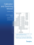
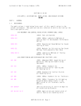
Document No. : MD-QO-04-281
Date :
2009/07 /17
Version : 1.0
FORGED STEEL GATE VALVES
FGT-800 Ansi Class 800
USER MANUAL
Modentic Industrial Corporation
14F-1,No.57Taya Rd.,Taichung,Taiwan,R.O.C.
Email:[email protected]
http://www.modentic.com.tw
WARRANTY
Modentic warrants its products against defects in manufacturing if the products
Are used for the purposes for which they are manufactured and sold. This warranty
Shall expire one year from date of shipments.
1. To use for company in Europe who will place the product on the market , please amend which
necessary.
2.Modentic reserves the right to change any details without prior notice.
Contents
1.
Caution
2.
Safety Precautions
3.
General
4.
Limitation
5.
Storage
6.
Installation
7.
Maintenance and Repair
8. Trouble-shooting Table
9. Stem Packing Replacement
10. Operation
11. Disassembly
12. Reassembly
13. Bolt Tightening Sequence
14. Dimensions and Materials list
Importer, Agent or Distributor responsible for servicing
Caution:
Please read these instructions carefully and thoroughly before installation. With proper installation and
adequate maintenance, Modentic valves are set to offer you a long and trouble-free service. Our priority is
to accomplish a safe working environment for both the personnel and the equipments.
Safety Precautions:
1. The valves are pressurized equipments, therefore appropriate safety measures have to be taken into
account while handling it.
2. Any alterations made on the valve without prior approval from Modentic in formal documentation are
not permitted.
3. All valves are designed for use within the limits specified herein and as described on the valve body.
Exceeding these limits is to be considered misuse and could lead to serious damage to the valve and its
working environment.
4. There is possibility that the (hazardous) pressurized fluids or gases could be trapped in the cavity of the
valve. Before removing the valve from its line of work, make sure this pressure is released and drained
by partly discharging the valve.
5. When personnel are maintaining a valve, adequate protection (eye, head, and body) and protective
clothing should be utilized at all time.
6. When the valves are operated on low- or elevated temperature, operating personnel must take special
notice to avoid injuries.
7. Valves and its accessories must not be used as the sole support foundation of the piping system.
also should not be the support of human weight by any means.
They
8. The designer of the piping system should be responsible for the safety accessories such as the safety
relief (when over-pressured).
9. It is the user/system designer’s responsibility to use insulation in high temperature applications.
10. Do not try to operate any valve that exhibits signs of leakage. Isolate the valve then either repair or
replace it.
General:
1. This manual covers Modentic ASME Class 150 through 2500, bolted bonnet, outside screw and yoke,
flanged, butt welded and socket welded ends, carbon steel, stainless steel and alloy steel valves.
2. Valve pressure varies under different models, sizes, working temperatures, and materials. Please verify
the application within the limits specified herein and as described on the Modentic metal plate that can
be found on the valve body. References contained in this document to the “PED” are in regard to the
European Pressure Equipment Directive 97/23/EC.
3. All personnel must take into consideration that while functioning in the piping system, the valves are
pressurized at all times. Therefore, appropriate safety measures have to be taken into account, and
protective equipments must be worn at all times with adequate precautions to safeguard against possible
accidents.
4. Always use Modentic recommended spare parts for maintenance and replacement.
5. Valve Marking
All the marking information should be cast on the body, or on a metal plate which is spot-welded to the
body. Valve with sizes above 1” for the European market should carry the CE mark with the
information required by the PED.
Limitation:
1. Valves are not to be used in safely functions such as safety loops or separating incompatible fluids.
2. To provide an optimum service, the valve should be operated only in its fully open or fully closed
position. If the valve is used in partly open (throttled) position, wedge life may be reduced.
3. Conditions supporting no greater than Category Ⅲ ( reference the PED) and for the gases and liquids in
group 1 & 2 (reference the PED)
4. The combined corrosion and erosion allowance for the valve body wall thickness is 1mm. When this
allowance has gone, the valve should on longer be used.
5. Prior to selection, it is the user’s responsibility to determine that the valve is appropriate for the intended
application. Application does not to allow corrosion >0.05mm/year.
6. The possibility of material deterioration in service and need for periodic inspections is responsibility of
the user.
Storage:
1. If valves won’t be installed into the pipeline immediately, the following steps should be observed.
A. Keep the valves wrapped and protected as they are shipped from the manufacturer.
B. Do not remove the protective and covering until the valve is ready for installation. This will reduce
the possibility of foreign material damaging internal valve components.
C. If the valves are stored outdoors, they should keep vertically. So that water does not accumulate in
the valve body.
2. If the valves body is carbon steel and will be stored for more than of one year, they should be stored in
the following manner.
A. Remove the protectors and coverings. Apply antirust grease to valve chamber.
B. Cover the valve in the plastic protectors.
C. Apply an antitrust grease (paint) to the external surface.
3. Do not store the valves outdoors.
4. The valves should be stored in waterproof conditions. They should be protected to safeguard against
humidity, moisture, dust, dirt, sand, mud, salt spray, and seawater.
5. Stainless steel valves do not need any additional protective coatings once installed as their natural finish.
6. Valves to be stored for a long period of time should be checked by the quality control personnel every six
months; and every three months for automated valves.
Installation
1. Remove the protectors and coverings.
2. Prior to the shipment effected from the manufactory, antirust grease might have been applied to the valve
chamber. The antirust grease could be removed by the solvent.
3. The internal parts of the valve have to be inspected and make sure that the compressed air has been
released.
4. Clean the adjacent pipes and make sure they are free from the debris to damage the valve.
5. Make sure the valve is positioned vertically. So that, the handle wheel ( or gear box ) have the enough
space to operate.
6. Gate valve is bi-directional and suitable to be installed for flow in either direction.
Flanged End
A. Bolting and gasket material should be compatible with the valve’s body material and pressure.
B. Care should be taken that flanges are straight and parallel.
C. Bolts should be evenly tightened in a star pattern. This will ensure a uniform gasket loading.
Welded End (include butt weld & socket weld)
A. Clean the weld ends as necessary and weld into the line using an approved weld procedure.
B. Make sure the body and pipe material given on the nameplate is compatible with the welding
procedure.
C. Only personnel qualified per ASME BPVC Sec. XI should weld pressure-containing components.
Only qualified weld procedures should be employed.
Maintenance and Repair
1. Before making the maintenance, always advise the maintenance personnel that the proper eye, head and
whole body protection always be utilized.
2. It is impossible to predict the frequency of the maintenance interval. The maintenance interval is
dependent upon several factors which are not foreseeable by the manufacturer.
3. Inspection
A periodic inspection should be performed on each unit. The time frame should be adjusted depending
on the frequency of the usage and service conditions. More frequent inspections have to be taken on a
valve which is opened and closed usually than a valve in constant service.
a. Examine the valve stem for cleanliness and lubrication. The stem threads should be coated with a
clean grease lubricant.
b. Some valves have a greased fitting in the bonnet or yoke. If it is dry, lubricate it.
c. Open and close the valve. The actions should be smooth without any binding of the stem through
full travel.
d. If valve is in service and under pressure :
1) Check the connection between the body and the bonnet if there is the leakage through the gasket.
If leakage is found, tighten the bonnet nuts evenly in a star pattern until the leakage stops. Do
not exceed the maximum torque values in Bonnet Bolt Tightening Specification. If there is
still leakage, see the Trouble-shooting Table.
2) Check if any leakage happens on the stem packing during the opening and closing action. If a
leak is found, tighten the gland nuts alternately with no more than a quarter turn on each nut
until the leakage stop. If there is still leakage, see the Trouble-shooting Table.
3) Inspect the exterior of the valves for cleanliness. Remove any dirt, grime or oil from the valve
body and bonnet.
After completion of a periodic inspection, valves that are providing satisfactory service require no
further disassembly or inspection. Should a valve be found which is not performing satisfactorily, see the
Trouble-shooting Table.
4. Maintenance
Except the periodic inspection, no routine maintenance is required. Routine replacement of parts, such as
gasket and packing is not usually performed until required. Once in service, it may become apparent that
these and other parts require repair or replacement due to usage and service conditions. A maintenance
schedule should be developed taking these conditions into consideration. Parts can be replaced during a
routine overhaul.
Stem Packing Replacement
Warning: To prevent injury ensure that all pressure is removed from the valve both upstream and
downstream before disassembly.
1. Remove gland nuts. Lift the gland and the stem, clean the packing chamber.
2. Remove the existing or defective packing rings with a sharp tool or packing remover. Do not
scratch or score the surfaces of the stem or packing chamber.
3. Examine the surfaces of the stem and packing chamber. Remove any scratches, scoring or burrs
with emerypaper or hand filing. Clean the stem with a solvent dipped rag.
4. Count original number of rings and measure the thickness of x-section. If it is not able to count or
measure the thickness of packing, follow the steps as below :
1.) Measure the stem diameter (OD), stuffing box diameter (ID), and stuffing box depth (d).
2.) Packing x-section (R) = (ID – OD)/2
3.) #rings = (1.25 x d)/R
5. Install new packing. Cut each ring at a 45∘angle and stagger the joints at 120∘, every fourth joint
will be in the same position as the first step. Install the rings individually by using a split ring spacer,
compressing each ring by hand- tighten, then have the quadrant turns on each gland nut.
6. When the packing are positioned, assemble the gland and gland flange. Alternately tighten gland
flange nuts in 1/4 turn once until eye bolts begin to get tight.
7. If gland travels more than the height of one packing ring into the packing chamber, insert one more
ring and repeat step 6 until chamber is filled.
8. Compare the tightness of the valve operation now with the one before replacement. If it is
considerably tighter than the original, back off 1/4 turn on each gland nut and re-check the
tightness.
9. Inspect the packing area to ensure the full compression, tight bolting and no leakage. If the leakage
occurs, tighten gland nuts at 1/4 turn increments until leakage stops.
Operation
1. By turning the hand wheel counter-clockwise, the stem, to which the wedge is attached at the base, is
drawn up through the yoke sleeve.
2. By turning the hand wheel clockwise, the action is reversed and the wedge is lowered into the closed
position.
Disassembly
Warning: To prevent injury ensure that all pressure is removed from the valve both upstream and
downstream before disassembly.
1. Using the handle wheel to rotate the stem until the valve is in the half open position. In order to have
easier reassembly of the valve for the unchanged operation, mark on the body & bonnet with a metal tool
or paint to clearly show the original position.
2. Once assured there is no more pressure in the line, loosen the body-bonnet bolting
3. Remove the body bonnet nuts and bolts. Lift the upper part ( bonnet-stem-wedge assembled) out of the
body and mark the orientations of body, wedge, bonnet for the reassembly later. Take care not to scratch
the seating surface.
4. Remove the gasket from the valve body.
5. Remove the wedge from the stem, carefully protecting the surface of the seat ring.
6. Loosen the hand wheel nut. Remove the hand wheel from the bonnet.
7. To remove the valve stem, loosen the gland bolting and gland. Lift the stem from the yoke sleeve by
rotating it counterclockwise and pulling from below until the stem is free of the packing chamber. Be
careful not to score or scratch the stem machined surface or the threads.
Reassembly
1. Thoroughly clean the valve interior and all components. Remove all scale, oil, grease or other foreign
material. Wipe the seating surface of the wedge and valve seat with a solvent soaked cloth. Clean the
body and bonnet flange surfaces and all bolting.
2. Install the stem carefully, slide it through the packing and gland until the threads are engaged with the
yoke sleeve. Slowly rotate the stem clockwise until it extends beyond the bonnet.
3. Place hand wheel in position atop the valve, tightening hand wheel nut
4. Position a new gasket on the body top flange aligned with the bolt holes. The gasket should not extend
over the open body cavity.
5. Do not reuse a gasket. The gasket may be coated with the light oil.
6. Install the wedge to the stem connection.
7. Lift the bonnet-stem-wedge assembly up and over the body
8. Check the location marks on the body top flange, bonnet flange and wedge. Carefully lower the
assembly until the body top flange and bonnet flanges and the location mark meet.
9. Again, caution must be used to prevent scoring or scratching of the seating surfaces.
10. Keeping the bonnet stationary, open the valve a few turns to ensure the wedge is not touching the seat.
11. Line up the body and bonnet holes. Make sure the gasket does not extend into any of the bolt
holes.Install the bonnet bolting and tighten in a star pattern to evenly load the gasket to the torque values
listed in Bonnet Bolt Tightening Specification.
12. Install new packing as per. Stem Packing Replacement
13. Align and center the gland in the packing chamber. Evenly tighten the gland nuts until snug, then
alternate tightening with no more than a quarter turn on each.
14. Open and close the valve using the hand wheel. The action should be smooth and regular through full
stem travel.
Body-Bonnet Bolt Tightening Sequence
d
L2
NPT
11
10
9
8
7
6
5
4
3
2
1
12
13
14
15
16
H
W
L1
L
(RF OR RTJ)
DIMENSIONS
NPS
d
1/2 21.8
3/4
27
1
34
1-1/4 42.5
1-1/2 48.5
2
61
L2
10
13
13
13
13
16
unit:mm
NPT
1/2
3/4
1
1-1/4
1-1/2
2
L1
15
18
18
19
19
25
L
76
92
106
120
114
144
W
100
100
125
160
160
160
H
145
150
175
200
205
230
MATERIALS LIST
NO
1
2
3
4
5
6
7
8
9
10
11
12
13
14
15
16
Name
MATERIAL
BODY
A105
F304(L)
F316(L
SEAT RING
A276 420
F304(L)
F316(L)
WEDEG
A276 410
F304(L)
F316(L)
F304+GRAPHITE
GASKET
F316+GRAPHITE
BONNET
A105
A304(L)
F316(L)
STEM
A182 F6
A304(L)
F316(L)
GLAND EYEBOLT
A193 B7
A193 B8
GLAND NUT
A194 2H
A194 8
YOKE NUT
A276 410
HANDWHEEL
60-40-18
A194 8
H.W.NUT
A194 2H
GLAND
A276 410
F304(L)
F316(L)
GLAND FLANGE
A216 WCB
F304(L)
F316
FLEXIBLE GRAPHITE
STEM PACKING
F304
PIN
CARBON STEEL
A193 B8
A193 B7
BONNET BOLT