1
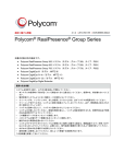
DWC-MPTZ5X DWC-MPTZ5XFM [Flush Mount] IP 2.1MP Pan Tilt Zoom Camera Before installing or operating the camera, please read and follow this manual carefully. 20140815 PRECAUTIONS Do not open or modify. Do not open the case except during maintenance and installation, for it may be dangerous and can cause damages. Do not put objects into the unit. Keep metal objects and flammable substances from entering the camera. It can cause fire, short-circuits, or other damages. Be careful when handling the unit. To prevent damages, do not drop the camera or subject it to shock or vibration. Do not install near electric or magnetic fields. Protect the camera from humidity and dust. Protect the camera from high temperature. Be careful when installing near the ceiling of a kitchen or a boiler room, as the temperature may rise to high levels. Cleaning: To remove dirt from the case, moisten a soft cloth with a soft detergent solution and wipe. Mounting Surface: The material of the mounting surface must be strong enough to support the camera. FCC COMPLIANCE This equipment has been tested and found to comply with the limits for a Class B digital device, pursuant to Part 15 of the FCC rules. These limits are designed to provide reasonable protection against harmful interference, when the equipment is operated in a residential environment. This equipment generates, uses, and radiates radio frequency energy, and if it is not installed and used in accordance with the instruction manual, it may cause harmful interference to radio communications. WARNING: Changes or modifications are not expressly approved by the manufacturer. 2 TABLE OF CONTENTS* Introduction.......................................................................................................................................................4 Features........................................................................................................................................................4 Parts .........................................................................................................................................................5-7 Dimensions...................................................................................................................................................8 Inside the Box ........................................................................................................................................9-10 Installation.......................................................................................................................................................11 Network Connection...................................................................................................................................11 Installation- Mounting MPTZ5X ...........................................................................................................12-14 Installation- Mounting MPTZ5XFM ......................................................................................................15-18 Installation- SD Card..................................................................................................................................19 MEGAPIX Camera Setup...............................................................................................................................20 Installing the IP Finder...............................................................................................................................20 Using IP Finder Software......................................................................................................................21-22 Network Options.........................................................................................................................................23 Upgrading Cameras using the IP Finder Software....................................................................................24 Camera Reboot..........................................................................................................................................25 MEGAPIX Camera Web Viewer.....................................................................................................................26 Accessing the Web Viewer via Internet Explorer.......................................................................................26 Accessing the Web Viewer via Google Chrome, Mozilla Firefox and Safari............................................27 GUI Description .........................................................................................................................................28 First & Second Stream...............................................................................................................................29 Export Image..............................................................................................................................................30 Print Image.................................................................................................................................................31 Instant Recording..................................................................................................................................32-33 Controlling the Camera using Virtual Joystick .....................................................................................34-35 MEGAPIX Camera Setup...............................................................................................................................36 Video ....................................................................................................................................................36-41 PTZ .......................................................................................................................................................42-48 Event ....................................................................................................................................................49-50 Network.................................................................................................................................................51-56 Record ..................................................................................................................................................57-60 System..................................................................................................................................................61-66 Specifications ...........................................................................................................................................67-68 Troubleshooting .......................................................................................................................................69-72 Warranty..........................................................................................................................................................73 Limits & Exclusions.......................................................................................................................................74 3 FEATURES* ONVIF Compliant, Profile S 2.1 Megapixels, 30fps at All Resolution Triple Codec, Simultaneous Dual-Stream 1/2.8” CMOS Sensor 5~25mm Zoom Lens 5X Optical Zoom with Auto Focus 12X Digital Zoom Auto Day and Night with IR Cut Filter Pan 0~350° Endless, 120° Per Second Pan Speed Vector Drive Technology [Pan/Tilt Motion in Shortest Path] 255 Preset Positions, 4 Sequences, 8 Swings, 8 Tours WDR [Wide Dynamic Range] 3D-DNR [3D Digital Noise Reduction] Motion Detection with E-mail Notifications Two-Way Audio [MPTZ5XFM Only] 1 Sensor Inputs, 1 Sensor Output [MPTZ5XFM Only] Micro SD/SDHC Class 10 Card for Emergency Backup (Not Included) IP66 Certified [Weatherproof] [MPTZ5X Only] Power Over Ethernet [PoE] & DC12V 4 PARTS & DESCRIPTIONS – MPTZ5X* Cover Dome Cover Dome Screws Camera Module Rubber Gasket 5 PARTS & DESCRIPTIONS – MPTZ5XFM* 6 PARTS & DESCRIPTIONS [MPTZ5XFM]* Camera Part Description 1 Audio Output Port Connection for audio output cables 2 Audio Input Port Connection for audio input cables. 3 Alarm In Connects to peripheral devices according to camera settings 4 Alarm Out Connects to peripheral devices according to camera settings 5 Network Cable Port RJ45 Cross over network cable connector 6 Power Port Connect 12V DC power source. 7 Micro SD Card Slot Enter a micro SD card for local emergency backup (not included) 7 DIMENSIONS – MPTZ5X* DIMENSIONS – MPTZ5XFM* 8 INSIDE THE BOX – MPTZ5X* 9 INSIDE THE BOX – MPTZ5XFM* 10 NETWORK CONNECTION* There are two options to power the MPTZ5X camera. Use a PoE-enabled switch to connect data and power through a single cable and begin viewing and recording images instantly. A non -PoE switch will require an adaptor for power transmission. 1. Using a PoE-Enabled Switch The MEGAPIX Camera is PoE compliant, allowing transmission of power and data via a single Ethernet cable connected to a PoE injector. PoE injectors eliminates the need for the different cables used to power, record, or control the camera. Follow the illustrations below to connect the camera to a PoE- injector using an Ethernet cable. 2. Using 12V DC If a PoE injector is not available, use a power adaptor for power transmission and a non-PoE switch for data transmission. Follow the illustrations below to connect the camera without a PoE Injector. 11 INSTALLATION [MPTZ5X]* Removing the protection parts Protection Foam Before staring the installation, remove protective foam from the camera’s lens. These are used to protect the camera module during shipment and should be completely removed before powering the camera. To do so: 1. Detach the Gasket from the bottom of the camera. 2. Detach the dome cover from the camera module by loosening the three screws on the cover dome. 3. Take off the protection P.E Foam from the dome cover and lens. 4. Assemble the dome cover bottom case by aligning the screw hole in the cover and bottom case. 5. Assemble the bottom gasket to the camera. Protection Foam Rubber Gasket 12 INSTALLATION [MPTZ5X]* Metal Mount Camera Installation 1. Using the metal mount plate, mark and drill the necessary holes in the wall or ceiling. 2. Pull wires through and make connections. 3. Using the two (2) included screws, mount and secure the camera to the wall or ceiling. 4. Attach the camera base to the metal mount by snapping it into place using the two metal handles. 5. Secure the camera’s cover dome onto the camera base to complete the installation. 13 INSTALLATION [MPTZ5X]* Soft Ceiling Mount Installation 1. Using the camera’s template, mark and drill the necessary holes in the wall or ceiling. 2. Secure the two (2) mount bolts into the camera’s bottom. 3. Pull wires through and make all necessary connections. 4. Insert the mount bolts into the template holes. 5. Fix the camera to the mounting surface by tightening the mount nuts to the mount bolts on the ceiling panel. 14 INSTALLATION [MPTZ5XFM] * Removing the protection parts 1. Before staring the installation, remove the lens cap and the fix tape. These are used to protect the camera module during shipment and should be completely removed before powering the camera. 2. The mounting surface must be able to sustain five times the weight of your camera. 3. Do not let the cables get caught in improper locations or it can cause damage to the cables. 15 INSTALLATION [MPTZ5XFM]* Installation using Screws 1. Detach the camera’s housing from the flush mount by rotating the camera counter clock-wise and pulling. 2. Use the mounting template to mark and drill the necessary holes in the wall or ceiling. 3. Pull wires through the Flush Mount Bracket. 4. Using the two (2) included screws, mount and secure the camera’s flush mount to the wall or ceiling. 5. Once the Flush Mount is securely mounted, make cable connections and insert the camera module into the bracket. Turn it clock-wise to lock it in place. Align the red dots on the body and the flush mount bracket. 6. Attach the camera’s bubble dome cover over the camera and remove the protective dome cover. 7. Select from the available accessories a deco-ring and attach it to the camera’s dome cover. 16 INSTALLATION [MPTZ5XFM]* Installation using Hooks 1. Disconnect the camera module from the Flush Mount Bracket. Use the mounting template to mark and drill the necessary holes in the wall or ceiling. 2. Pull wires through the Flush Mount Bracket. 3. Insert the flush mount bracket into the mounting ceiling or wall. 4. To hook the flush mount bracket to the mounting surface, push and turn the head screw clock-wise using a Philips driver. The hook’s head should then grab onto the ceiling’s inside side. Repeat for both hooks until the flush mount is secured to the ceiling. 5. Once the Flush Mount is securely mounted, make cable connections. Insert the camera module into the bracket. Turn it clock-wise to lock it in place. Align the red dots on the body and the flush mount bracket. 6. Attach the camera’s bubble dome cover over the camera and remove the protective dome cover. 7. Select from the available accessories a deco-ring and attach it to the camera’s dome cover. 17 INSTALLATION [MPTZ5XFM]* Cabling Use the diagram below for proper cabling of peripheral devices such as audio input (microphone) and audio output (speaker). Use the Audio and Alarm Cable connector to connect all external devices to the camera: External Devices and corresponding cables: 1. Audio In ( Orange) 2. GND (Green) 3. Audio Out (Brown) 4. GND (Blue) 5. Alarm In + (White) 6. Alarm In – (Yellow) 7. Alarm Out + (Black) 8. Alarm Out – (Red) Audio IN: The cables from the audio input device should connect to audio in and GND in the cable slot. Then activate the audio input device in the camera’s web viewer. Alarm IN: The cable from a sensor/ alarm input device should connect to alarm in+ and alarm in – in the cable slot. Sensor/ alarm in can be adjusted from the camera’s web viewer. Audio OUT: The cables from the audio output device should connect to audio out and GND in the cable slot. Audio volume is controlled in the camera’s web viewer. Alarm OUT: The cables from an alarm output should connect to alarm out+ and alarm out – in the cable slot. Alarm output can be adjusted from the camera’s web viewer. * Available in MPTZ5XFM Models only 18 INSTALLATION* SD Card Use the diagram below for installation of an SD Card for local emergency backup. When setup properly, the camera will record to the local SD card when it detects it is not recording to any servers and is not connected to the network. SD Card Slot in the MPTZ5X SD Card Slot in the MPTZ5XFM 19 IP FINDER SOFTWARE* Installing IP Finder Software IP Finder searches for all the available Digital Watchdog devices currently connected to your network. 1. Install IP Finder to find the MEGAPIX camera on your local network. The software can be found on the included User Manual CD. Run IP Finder and install onto your PC. 2. When setup is complete, launch IP Finder . 3. To find your MEGAPIX camera, click Search button. Your MEGAPIX camera will appear as ”DWC-MPTZ5X.” 4. Select the desired device and click Web Connect to access the camera directly via Internet Explorer. *Install the IP Finder to a computer located on the same Subnet Mask as the MEGAPIX camera. 20 IP FINDER SOFTWARE* Using IP Finder Software Use IP Finder to change the basic settings of your MEGAPIX camera or to connect to your MEGAPIX camera. 1. Configuration: Change the device’s connection type and/or IP address information. Please see the next page for further explanation. 2. Upgrade: Upgrade the device’s firmware. 3. Time zone: Change the time zone. 4. Import Configuration: Import setup configuration for a specific device. 5. Web Connect: Connect to the MEGAPIX camera through Internet Explorer. [5] [4] [3] [2] [1] 21 IP FINDER SOFTWARE* Using IP Finder Software Use IP Finder to set the connection type and the IP address information for your MEGAPIX camera. 1. DHCP: Select DHCP to access the camera within the same internal network. For further explanation on DHCP, please see PAGE 24. 2. PPPoE: requires previous registration. Enter the username and password. 3. Static IP: Select Static to connect to the camera from an external network. For further explanation on Static, please see PAGE 24. 4. Use DDNS: Check this option to use DDNS service. For further explanation on DDNS, please see PAGE 24. 5. Port: The port numbers required for communication with the camera. Use the IP Finder to change other basic settings for your MEGAPIX camera. (The menu [4] options may vary depending on the [1] camera model.) [2] [3] [5] *If you change the camera’s IP, write down the camera’s MAC Address for identification in the future. 22 IP FINDER SOFTWARE* DHCP The Dynamic Host Configuration Protocol (DHCP) is a network configuration protocol that allows a device to configure automatically according to the network it is connected to. If your network supports DHCP and your MEGAPIX camera is set to DHCP, IP Finder will automatically find and set your MEGAPIX camera to correspond with your network requirements. Static Static IP addresses are recommended when using a network that does not support DHCP or when setting your device to be accessed externally via the internet. If Static is selected, you must manually enter the correct network settings for your MEGAPIX camera. The settings will correspond with your network. To set your camera to a static IP address, we recommend that you (1) setup the camera to DHCP, (2) allow it to configure itself according to your network, and (3) change the settings to a static IP address. 1. To set your MEGAPIX camera to Static, highlight the desired device from the search results list, and click on Configuration. In the “Network Configuration” window, make sure Static is selected. 2. Enter the following information: IP Address, Netmask, Gateway, and Preferred DNS. 3. Click Apply and Reboot to save all changes. DDNS Dynamic Domain Name Server is a feature that allows you to use a specific URL instead of an IP address to access your MEGAPIX camera. This feature is optional. It may require a subscription and fee. 1. To use the DDNS feature, check the box next to Use DDNS. 2. Select the server you wish to use. *Some servers may require a subscription and fee. 3. If applicable, enter the User ID and Password. 4. Click Apply and Reboot to save all changes. 23 IP FINDER SOFTWARE* Upgrading Cameras using the IP Finder Software Use IP Finder to perform firmware upgrade to all your MEGApix cameras from one convenient location. 1. Select all the cameras you would like to upgrade. You can select multiple cameras by clicking on multiple camera models while holding down the Ctrl button. 2. Press the ‘Upgrade’ button. 3. Browse and select the appropriate file to use for the upgrade. Press the ‘OK’ button. 4. The system will start updating all the selected cameras in a new window. 5. The system will indicate if the upgrade was successful or not for each camera. 6. When all cameras have been properly upgraded, press the ‘Close’ button 7. To complete the upgrade, reboot the cameras by pressing the ‘server reboot’ button. 8. Press the ‘Exit 9. Allow up to 60 seconds for the cameras to reboot and press the ‘Search’ button. If the cameras reappear in the IP Finder the reboot is complete and the camera is ready. [5] [1] [3] [6] [8] [4] [7] [2] * IP Finder can perform multiple upgrades at the same time only for the same camera models. Some cameras may require different firmware depending on the model. 24 CAMERA REBOOT* Resetting the Camera Pressing the reset button on the camera’s control board for five (5) seconds while power cycling the camera will initialize all environmental variables to factory default. Previous setup for IP default, time, etc. will be deleted. To reset the camera to its factory default settings: 1. Turn the camera Off (unplug from PoE Switch) 2. Press and hold the ‘Reset’ button and turn the device On (Connect PoE cable to camera). 3. Hold the Reset button for 5 seconds while the power is on. 4. The camera would be set to its default settings. The following are the default network settings. IP Mode DHCP IP Address 192.168.1.123 Subnet Mask 255.255.255.0 Gateway 192.168.1.23 Command Port 7000 HTTP Port 80 Live Port 7001 Reset Button in the MPTZ5X Reset Button in the MPTZ5XFM * Frequent use may cause system error. 25 WEBVIEWER* Remote Video Monitoring Via Internet Explorer Monitor and configure the MEGAPIX camera through a built -in web viewer. 1. Type the IP address of the camera on the Internet Explorer window. Example: http://192.168.1.123 (Factory Default) 2. Enter Username and Password Username: admin | Password: admin 3. The web browser will ask to install ActiveX Control. Once it has been installed, Internet Explorer will display video images from the camera. 26 WEBVIEWER* Remote Video Monitoring Via Chrome, Firefox, or Safari You can view your MEGAPIX camera using web browsers other than Internet Explorer. To do so, at least one of the streams of the camera must be set to the codec MJPEG. 1. Open Google Chrome, Mozilla Firefox, or Apple Safari Web Browser. 2. Enter the IP camera's IP address. If the first stream is set to H.264; then a video will not be displayed on the GUI. 3. Click the Setup button located at the top right of the page. Then go to Video > Stream Settings. 4. Modify one of the two (2) streams to the codec MJPEG. 5. When you are finished modifying the streams, click Apply and Reload to make sure all changes have been saved and your camera has been rebooted. 6. Click on Live View to return to the camera’s main page. 7. At the bottom of the page, select the stream you set as MJPEG. The camera will begin streaming video. 27 WEBVIEWER* Main Display Area GUI Description Alarm Status Computer’s Date & Time Camera’s Name Full Screen Mode Camera’s Time Access Setup Menu Export Camera’s Current Display as JPEG Print Camera’s Current Display Start/ Stop Panic Recording Show/ Hide PTZ Virtual Controller PTZ Virtual Controller Stream’s Name Camera’s IP Address Stream Control Sensor Control* Relay Control* 2-Way Audio Control* * Available in DWC-MPTZFM models only. 28 WEBVIEWER* First Stream & Second Stream Configure two stream settings for monitoring and recording. On the main monitoring page, user can view the camera with the First Stream settings or the Second Stream settings. Below the display screen, click on the First Stream and Second Stream buttons to view the different camera settings. To Setup Stream Settings, refer to page 42. [Streams Selection] 29 WEBVIEWER* Export Image Export a screenshot of the current live video to your computer. 1. Click Export Image button located on the left. “Save As” window will appear. 2. A .jpg image will automatically be stored under a WNMDWViewer folder. 3. The image’s name will include the camera’s IP address, Channel name, and date and time. [Export Image] 30 WEBVIEWER* Print Image Print a screenshot of the current live video. 1. Click Print button, and the Print Preview window will appear. 2. Scale the size of the screenshot or adjust the orientation of the screenshot. 3. To print the information about the screenshot, select View Title. To add a memo for the screenshot, click Page Option. 4. Go to Printer Setup to select the printer and manage the printer properties. 5. Select Print to print the page, or Close to cancel the print. [Print Image] 31 WEBVIEWER* Instant Recording Record live video to your local drive. To Setup Instant Recording 1. Click on the Record button located to the left of the Web viewer. 2. Setup where you want the videos to be saved. 3. Setup the duration of the instant recording. You can record up to 120 seconds of live video. 4. When setup is complete, click OK to save changes or Cancel to cancel any changes. [Local Recording] 32 WEBVIEWER* Instant Recording Record live video to your local drive. To Start and Stop Instant Recording 1. To Start, right-click anywhere on the display screen. 2. Click on Start Rec. The icon on the top right of the screen will change to INSTANT. 3. To Stop, right-click anywhere on the display screen. 4. Click on Stop Rec. The video will be displayed in the designated folder when recording is complete. [Local Recording] 33 WEBVIEWER* Controlling the Camera using the Virtual Joystick Use the different buttons in the Pan/ Tilt Controller to adjust the camera’s position, zoom and focus, and control the camera’s PTZ functions. To control the Camera’s Pan, Tilt, and Zoom: 1. Pan Tilt Buttons- The Pan-Tilt wheel enables you to move the camera in eight (8) directions by clicking and holding with your mouse’s left button on the corresponding button. The direction of each button depends on its location on the wheel. For example, pressing the central upper button will move the camera UP. To stop the camera’s movement, release the mouse’ button. 2. Zoom Control Button- The Zoom ratio of the camera can be controlled by using the ‘+’ and ‘-’ buttons. Press the ‘+’ to make the camera zoom into the center of the image. Press ‘-’ to make the camera zoom out to the full field of view. 3. Focus Control Button- Not supported in this camera model. 4. Iris Control Button- Not supported in this camera model. 5. Speed Control Button- The pan-tilt speed can be controlled by clicking on the Speed bar and moving it left and right. Move the speed bar to the left to reduce the camera’s speed. Move the speed bar to the right to increase the camera’s speed. [1] [2] [3] [4] [5] 34 WEBVIEWER* Controlling the Camera using the Virtual Joystick Use the different buttons in the Pan/ Tilt Controller to adjust the camera’s position, zoom and focus, and control the camera’s PTZ functions. To control the Camera’s Pan, Tilt, and Zoom 6. 7. 8. 9. Swing Button- The Swing button enables you start and stop any of the previously set Swing commands. When the swing function runs, the camera moves between two (2) assigned positions based on the direction set by the user* [8] P-Seq Button- the Preset Sequence button allows you to start and stop any previously set Preset Sequence commands. A Preset Sequence is a group of presets ran in order, with the camera moving from one preset to the next according to the order and dwell time set by the user.* [7] Tour Button- the tour button allows you to start and stop any of the previously set tour commands. The Tour function allows users to run sequences of presets and swings. Each tour can have a maximum of 20 action.* [6] Presets buttons- the numeric buttons 1-10 allow you to send the camera to a specific preset previously setup. Press the preset number to move the camera to that position.* To move the camera to a saved preset from the main viewer: a. Select the Preset’s number from the available buttons. b. To activate presets higher than 10, expand the Advanced Menu option and use the numeric buttons to select a preset. c. Select to move the camera to a preset, set the preset to current position, or delete the preset. 10. Advanced Menu- Use the Advanced Menu to delete, set and move presets, as well as activate all 4 Sequences, 8 Groups and Swings. * [9] [10] * See pages 43-46 for more information on how to setup presets, swings, sequences, and tours. 35 WEBVIEWER* Setup > Video > Stream Settings The MEGApix camera allows you to setup two different streams to optimize storage and bandwidth usage. 1. Name- Set a unique name to each stream to identify them. 2. Resolution- Set Resolution for each stream. The better the resolution, the more bandwidth it will require to stream images. 3. Compression Type (Codec)- Select the type of compression to use when outputting the video. The compression type affects the image quality, bandwidth, and file size of saved images. MJPEG, the lowest Compression type, will provide the highest image quality, but also will cause the image size to be the largest, and take up the most bandwidth. H.264 Baseline Profile is the default codec. 4. Data Transfer Speed- Set encoding bitrate if H.264 and MPEG4 compression type is selected. Select from 1800 to 8000Kbps. 5. Frame-rate- Select from 0fps to 30fps. The camera is set by default to 28fps. 6. MJPEG Quality- Set MJPEG image quality. This is only available when the compression is set to MJPEG. The higher the quality, the more bandwidth will be required to stream the image. 7. Select ‘Apply’ to save changes. [1] [2] [3] [4] [5] [6] [7] 36 WEBVIEWER* Setup > Video > Color Settings Use the color settings menu to adjust the camera to its unique lighting environment and to get the best image quality. White Balance: Also known as Color Balance. This gives the camera a reference to “true white.” White Balance is used to make colors appear the same in the Field of View (FoV) no matter what is the light temperature of the light source. Select from Auto, or Manual. If AUTO, AUTO Ext, Indoor, or Outdoor are selected, the camera will automatically adjust itself to the proper white balance. If PRESET is selected, white balance is fixed based on current lighting. To activate, press ‘Push’. If MANUAL is selected, adjust the following values: Kelvin- Determines the warmth or coolness of the light. Select from Low, Middle, or High. White Balance Red Offset- select from 0~20 range. The lower the number, the image will appear green. The higher the number, the image will appear red. Default value is 10. White Balance Blue Offset- select from 0~20 range. The lower the number, the image will appear yellow. The higher the number, the image will appear blue. Default value is 10. [White Balance Settings] Select: ‘Apply’ to save changes, ‘Reload’ to return to the last saved settings, or ‘Default’ to return all settings to their factory default values. 37 WEBVIEWER* Setup > Video > Color Settings Use the color settings menu to adjust the camera to its unique lighting environment and to get the best image quality. Auto Exposure: Set Digital Slow Shutter, Gain, Brightness, AGC, BLC, & WDR. Auto Exposure can be set to Auto (Default), or Shutter mode. Digital Slow Shutter- Slow shutter mode decreases the shutter speed in low light to improve the image quality. Set the camera’s digital slow shutter for: Off, 2x ~ 8x. The smaller the value the darker the image will appear. (Available only when Auto Exposure is set to Auto mode). Shutter speed- Set the camera’s shutter mode to Auto or manual. If manual is selected, select the shutter speed. Select from the available options between 1/30 and 1/60000. Select 1/30 to set more exposure time to light. This setting is used to make movements look natural/ unfrozen. Select 1/60000 to set less exposure time to light. This settings is used to catch fast moving objects. (Available only when Auto Exposure is set to Shutter mode). Gain- Maximum light gain settings in low light conditions. Select from 0dB (least light) to 41dB (most light). Default is 41dB. Brightness- Set the brightness of the camera’s image from 0~20. The higher the number, the brighter the camera’s image will appear. Default is 10. [Auto Exposure Settings] 38 WEBVIEWER* Setup > Video > Color Settings Use the color settings menu to adjust the camera to its unique lighting environment and to get the best image quality. Auto Exposure: Set Brightness, Shutter Mode, Digital Slow Shutter Speed, AGC, BLC, & WDR. HLM [Highlight Mode]- Masks highlights for objects to appear clearly on the screen. BLC [Backlight Compensation]- This setup option allows you to adjust the camera’s capture of light when there is strong backlight in the camera’s Field of View [FoV]. WDR [Wide Dynamic Range]- the Wide Dynamic Range is used when there are extremely bright and extremely dark areas in the FoV of the camera. If WDR is selected, select the WDR level from: Low, Middle, High. Default is Middle. (These features are available only when Auto Exposure is set to Auto mode). Day & Night Settings: control the camera’s Day & Night Mode. Day & Night- Set mode to Night (B/W), Day (Color), or Auto. Threshold- If Auto is selected, adjust the Threshold value. This value determines when the camera switches from color to B/W and vice versa. The higher the number, the brighter the scene will be before switching between Color and B/W. [Manual Exposure Settings] [Day & Night Settings] 39 WEBVIEWER* Setup > Video > Color Settings Use the color settings menu to adjust the camera to its unique lighting environment and to get the best image quality. Extra Settings: control the camera’s Day & Night Mode, Focus, WDR, Flip, Digital Zoom, Defog & Frequency Levels, and Noise Reduction. Mirror Mode- reflect the image from left to right. Flip- Select On or Off to flip the image upside down. Digital Zoom- Enable or disable the use of digital zoom in the camera’s web viewer. Sharpness- Sets the image sharpness. The higher the number, the sharper the image. Digital Noise Reduction- Control the level of noise in the image. Select from Off, Level 1 – Level 5. The higher the level, the more the camera will manipulate the image to reduce digital noise, but it will also increase lagging when motion occurs. Defog- Sharpens the camera’s image to compensate for blurry view due to weather conditions. Frequency- In case the camera’s image is flickering, adjust the value on this setting. [Extra Image Settings] 40 WEBVIEWER* Setup > Video & Audio > Audio * Available in DWC-MPTZFM models only. Connect speaker/microphone wires (not included) to your camera and to a monitoring device (ex.: PC computer). 1. On the Display Screen in your Web Viewer, go to Setup, Video & Audio, and finally, Audio. Adjust settings to your preference. a. Audio Input: Set Gain (0-5) b. Audio Output: Set Buffering Time & Volume (0-5) c. Network Transfer: Select Transfer Audio regardless of video. d. Select Apply to save changes. 2. On the Display Screen, change Audio (in the bottom left corner) from OFF to 1. This will enable you to hear external audio. 3. To transfer audio to the camera, select the ‘headset’ button beneath Audio. [a] [1] [b] [c] [d] [3] [2] 41 WEBVIEWER* Setup > PTZ> Basic Use the MPTZ5X’s PTZ basic settings menu to adjust the features related to the camera’s speed, home action and zoom and focus. Speed 1. Set the camera’s Pan speed by seconds. Select from the drop-down menu value between 1 and 120. Default is 120.* 2. Set the camera’s Tilt speed by seconds. Select from the drop-down menu value between 1 and 120. Default is 120.* 3. Set the camera’s Zoom speed. Select from the drop-down menu value between 1 and 8. The higher the number the faster the camera will zoom in and out. Default value is 4. Miscellaneous 4. Power Up Action- If power up action is set to be on, camera will continue the function which is executed lastly after rebooting. Default is ON. [Speed Settings] [1] [2] [3] [Miscellaneous] *The values for both the Pan and Tilt speed are the number of degrees the camera will travel per second. For example, at the default value, the camera will travel 120°/ Sec when controlled by the user. 42 WEBVIEWER* Setup > PTZ> Preset & Sequence Configure and modify the camera’s Presets. The MPTZ5X supports up to 255 different presets. A Preset is a unique command users can assign the camera. To configure the camera’s Presets: 1. Select the preset # you would like to set or modify from the drop down menu. If a preset has not been setup previously, [Undefined] will appear next to the preset’s number. 2. Using the virtual joystick next to the camera’s preview screen, move the camera to the position you would like to associate with the selected preset. 3. When the camera is positioned at the desired location for the preset, press the ‘Set’ button to save that location to the selected preset. 4. Select the Dwell time. This value indicates how long the camera will remain on the preset before moving to the next one during a sequence. Select from 1 to 60 seconds. [2] 5. Select ‘Clear’ to delete a preset’s position. 6. Select ‘Clear All’ to delete all the previously set presets. 7. Select ‘Move’ to move the camera to a preset selected from the drop[4] down menu. If the camera has [1] [Unidentified] next to the Preset’s [3] number, Move function will be disabled. [5] 8. Click ‘Apply’ to save the changes.* [6] [8] [7] * See pages 34-35 for more information on how to control presets from the camera’s main viewer page. 43 WEBVIEWER* Setup > PTZ> Preset & Sequence Use this setup menu to configure and modify the camera’s Preset Sequences. The MPTZ5X supports up to 4 different Sequences. A Sequence is a group of presets ran in order, with the camera moving from one preset to the next according to the order and dwell time set by the user. To configure the camera’s Sequence: - Select the Sequence you want to setup from the drop down options. - Enter the Preset numbers in the corresponding Sequence space, separating the presets with a comma (,).* The order in which you enter the presets is the order in which the camera will use to run the sequence. - Use the dwell time to determine how long the camera will stay on each preset before moving to the next preset. See page 44 for more information. - See page 36 for how to control Sequences from the camera’s main viewer page. [Preset Sequence Settings] * You must have at least two (2) presets set to properly setup a Sequence. 44 WEBVIEWER* Setup > PTZ> Swing Use this setup menu to configure and modify the camera’s Swing feature. When the swing function runs, the camera moves between two (2) assigned positions based on the direction set by the user. The camera supports up to 8 different Swing patterns. To setup a Swing: 1. Select the Swing# to set or modify from the drop down menu. If a Swing has not been setup, [Undefined] will appear next to the Swing’s number. 2. Using the virtual joystick next to the camera’s preview screen, move the camera to the position you would like to set as the ‘First Position’. 3. Press the ‘First Position’ button to save that location. 4. Repeat steps #2 and #3 to set the Swing’s ‘End Position’. 5. Press ‘Delete Swing’ to delete a previously set Swing. 6. Set the speed in which the camera [2] will travel between the positions from the drop down menu. Available range is from 1 to 180.* 7. Select the Dwell time. This value [7] indicates how long the camera will remain on each position before [1] moving to the next position. Select from 1 to 60 seconds. [6] 8. Use the ‘Run Swing’ and ‘Stop Swing’ to test the swing and make [3] any necessary modification. [4] [5] [8] * The values are the number of degrees the camera will travel per second. For example, at the default value, the camera will travel 30°/ Sec between positions. 45 WEBVIEWER* Setup > PTZ> Tour Use this setup menu to configure and modify the camera’s Tour feature. The Tour function allows users to run sequences of presets and swings. Each tour can have a maximum of 20 action. The MPTZ5X supports up to 8 Tours (Groups). To setup a Tour: 1. Select the Tour/ Group number from the drop down menu at the top left corner of the setup page. 2. Assign a function to each action value. Select: a. Preset# 1~255 b. Swing# 1~8 3. Set the dwell time for each action. Select from 1 to 60 seconds. This value indicates how long the camera will remain on the preset [1] before moving to the next one. Default is 5 Seconds. 4. Set the number of times the action will be repeated in the tour before [2] moving to the next action. This setup is for Swing options only. [3] Default is 1. 5. Click ‘Apply’ to save the changes. [4] [5] * You must have at least two (2) presets and one (1) Swing set to properly setup a Tour. ** See page 34-35 for more information how to control Tours from the camera’s main viewer page. 46 WEBVIEWER* Setup > Event > Motion Detection [1] [2] [3] [4] The Motion detection feature allows the MEGApix camera to detect motion and trigger an alarm. To set the camera to send e -mail notifications for every motion triggered alarms, see page 45. 1. Check the Use Motion box. 2. Sensitivity- Select from Low, Middle, or High. 3. Dwell Time- When a motion is triggered, the camera can be set to record for a certain period of time. Dwell Time can be set up to 900 seconds. 4. Select Apply to save changes. To setup specific areas of the camera’s view to motion detection, please see the next page. 47 WEBVIEWER* Setup > Event > Motion Area The Motion detection feature allows the MEGApix camera to detect motion and trigger an alarm. To set the camera to send e -mail notifications for every motion triggered alarms, see page 45. 1. Using the virtual joystick next to the camera’s preview screen, move the camera to the position you would like to set for motion detection. 2. Hold left mouse button and drag the mouse pointer over image to select the motion area, or use Set All button to select the entire screen. 3. Select Clear All to deselect motion areas. 4. Select Apply to save changes. 48 WEBVIEWER* Setup > Event > Sensor Settings * Available in DWC-MPTZFM models only. The MEGApix PTZ camera supports one (1) sensor connections and 1 Relay output connection. To Use a Sensor or Relay: Sensor- Select sensor type(NO/NC) and check sensor number. To use relay out, check relay number and set time to activate. - NO(Normal Open): Sensor is activated when it closes. (Example: Door normally remains open and an alarm is triggered when the door closes.) - NC(Normal Close): Sensor is activated when it opens. (Example: Window normally remains closed and an alarm is triggered when the window is opened.) Relay Activity- To use Relay Activity, select USE and set time to activate. Select Apply to save changes. [Sensor Input Settings] [Relay Output Settings] 49 WEBVIEWER* Setup > Event > Emergency Alarm The Emergency Alarm option allows the camera to send a notification when an alarm is triggered to a predefined destination (i.e. remote client software). 1. Site Information- Site Name, Transmission Settings, and Video Duration for the video that will be sent when motion is detected. 2. Emergency Alarm Recipient List- Enter the IP address and the Port for the remote site(s) to which you want to send the video. You can set-up up to five different servers. You must set same port to get EACH data. 3. Event for Emergency Alarm- Select which type of event will trigger the alarm – Motion or Sensor. 4. Select Apply to save changes. [Site Information] [Emergency Alarm Recipient] [Events for Emergency Alarm] 50 WEBVIEWER* Setup > Network > Network Settings Use this setup page to adjust the camera’s network settings, including the IP address, DNS information, and ports. In the IP Mode section, select the type of IP address for the camera. 1. DHCP- Select if using a DHCP Server and camera will to obtain an IP address automatically. 2. PPPoE- Select when using a WAN service. Enter a Username and Password from your ISP. 3. Static IP- Enter IP information if you decided to give the camera a static (fixed) IP address. a. IP Address- Enter the static IP Address of the camera b. Subnet Mask- default is 255.255.255.0 c. Gateway- your router’s external (public) IP address. It is used when accessing the camera from outside the network. The router will channel your data to the correct destination even if it is on a different subnet mask. d. To obtain a static IP Address and network information, contact your Internet Service Provider or Network Administrator. 4. DNS- Enter Primary DNS and Secondary DNS. The Domain Name Server translates web addresses to IP addresses. 5. IPv6 Mode- IPv6 offers a new 128-bit address system. 6. MAC Address- Displays the camera’s Mobile Access Control Address. 7. Port- Displays all the ports necessary for communication and router setup. 8. Use Flow Control- Control the network stream (quality & Frame rate) pending on the network circumstance. 9. Select ‘Apply’ to save all changes and reboot the server. 51 [1] [2] [3] [4] [5] [6] [7] [8] WEBVIEWER* Setup > Network > Dynamic DNS If you do not use a public IP address, DDNS provides you to connect on WAN. DDNS allows you to connect to the MEGAPIX camera with a URL address instead of an IP address. DDNS automatically redirects traffic to your IP address every time it changes. 1. To use DDNS, select the Use DDNS checkbox. 2. Select one of the DDNS System Names from the drop down list. 3. Enter Username & Password. The Username & Password must be registered at the DDNS site. 4. Enter Host Name. 5. Reboot your system to apply the changes to your camera. To Reboot, select Apply. A dialogue box will appear, select OK. System will automatically restart and may take up to 20 seconds to reboot. [1] [2] [3] [4] 52 WEBVIEWER* Setup > Network > Communication Protocol Current Protocol displays the current selected protocol. 1. To change the Protocol, select one of the three options—TCP, UDP, or Multicast. 2. If you select Multicast, enter the Multicast IP and Multicast Port. 3. Reboot your system to apply the changes to your camera. To Reboot, select Apply. A dialogue box will appear, select OK. System will automatically restart and may take up to 20 seconds to reboot. [1] [2] 53 WEBVIEWER* Setup > Network > Access Permission Use the Access Permission page to allow or block specific IP addresses to connect to the camera. 1. Select Allow All to allow anyone to connect to this camera. If Allow All is selected, the Allowed IP List and Blocked IP List will be ignored. 2. To allow only a specific list of IP addresses to connect to this camera, select Allow. Enter an IP Address and click the Add button. 3. To block a specific list of IP addresses from connecting to this camera, select Block. Enter an IP Address and click the Add button. [1] [2] [3] 54 WEBVIEWER* Setup > Network > OnVIF OnVIF is the Open Network Video Interface Forum. 1. To use OnVIF, check Enable. 2. Select the number of streams the camera will be sending using the OnVIF protocol. This may vary depending on the software and server you use. Consult your NVR’s manual for additional information. The camera will be set to dual stream on OnVIF by default. 3. Service Port will be set by default to “8032.” This is the camera’s OnVIF port. Use this port information when connecting the camera to a server using the OnVIF protocol. 4. Select On or Off to Authenticate Address. 5. Select On or Off for WS-Discovery (Web Services Dynamic Discovery) 6. Select Apply to save changes. [1] [2] [3] [4] [5] [6] 55 WEBVIEWER* Setup > Network > RTP/ RTSP Real-time Transport Protocol (RTP) and Real-time Streaming Protocol (RTSP) are data transfer protocol for delivering live and stored media to one or more clients at the same time. These protocols allow software to access the first and second stream directly, by assigning each stream its own ports. RTP and RTSP are used for integration and communication between the cameras and other software. To use RTP/ RTSP: 1. Check the box to enable authentication on RTSP 2. If necessary, modify the ports for the first and second stream. 3. Click ‘Apply’ so save all changes or ‘Reload’ to view the last saved settings. [1] [2] [3] 56 WEBVIEWER* Setup > Record > Storage Device Device Information 1. 2. 3. 4. 5. 6. Click the icon Load Device Information to find the SD card connected to the camera. The system will display all storage devices currently connected to the camera. To activate the SD card to start recording, select Record Start. To stop the SD card’s recording, select Record Stop. To safely remove the SD card, select ‘Device Eject’. To delete all content on the SD card, select ‘Format Device’. NOTE: all data stored on the SD card will be erased. Recording Information 7. This section displays the first and last recorded data available on the selected SD card. The SD card records video from the second stream. To modify recording quality, please see page 42. [1] [2] [5] [3] [4] [6] [7] IMPORTANT: The SD card recording function operates as an emergency recording, designed to record video from the camera only when there is a network loss. If you connect to the camera via the Web viewer or an NVR, the SD card recording will stop. 57 WEBVIEWER* Setup > Record > Schedule The recording schedule applies to the SD card local recording. When the camera detects a network loss, it will start recording backup video to the SD card based on the schedule setup. Video Schedule 1. Set recording schedule daily or weekly. Default is daily setting. It only saves single day’s setting wi thout changing to ‘Multi Day Mode.’ 2. Select the type of recording: Continuous (Cyan), Motion (Yellow) & Sensor (Red) by clicking on the corresponding button. 3. Drag your mouse over the hours you want to set for motion recording. The recording mode will be applied to the hours you selected when you release the mouse’s right-click. 4. To remove scheduled recording for a specific day, select ‘No Record’ and press the box for which hours you want the recording removed. The box will now appear white. 5. Select Apply to save changes, or Reload to view the last saved settings. [1] [3] [2] [4] [5] 58 WEBVIEWER* Setup > Record > Schedule The recording schedule applies to the SD card local recording. When the camera detects a network loss, it will start recording backup video to the SD card based on the schedule setup. Recording Control 6. 7. 8. 9. Pre-Alarm Time- Save previous image of event for duration of time. Motion Post-Alarm Time- Save images after motion events for duration of time. Overwrite- If selected, once the SD card is full, new video will be recorded over older data. Key Frame Only- If selected, the SD card will record only Start and End Key Frame, the main frames in the series. This option is recommended when you have limited storage space. 10. Select Apply to save changes. [6] [7] [8] [10] [9] 59 WEBVIEWER* Setup > Remote Backup Tab The MEGApix Series allows you to back up your SD card locally to your computer without the need to remove it from the camera. 1. Go to the Remote Backup Tab in the camera’s Setup menu. 2. On the calendar, select the date for remote backup. a. Days with recorded data will be indicated in BOLD. b. Hours with recorded data on them will be indicated by the pink line in the time bar. 3. Select the Backup Start Time and Backup End Time. 4. Select the Target Drive. The Target Drive is where the remote backup will be saved. 5. You can also use the interactive time bar. a. Right-click on the time you want to set as Start Time. b. Left-click on the time you want to set as End Time. c. The time frame you have selected will appear in BLUE. 6. Select Backup Start. To cancel a backup in progress, select Backup Cancel. [1] [2] [3] [4] [6] [5] 60 WEBVIEWER* Setup > System > Upgrade Upgrade the MEGApix camera and reset it to factory default. Camera Information- Shows the camera’s model name, current firmware, Kernel, and Server versions, and the camera’s internal Flash size memory. This is the camera’s internal memory necessary, for the camera’s operation, and cannot be used for recording locally. Manual Upgrade- To upgrade system firmware, you have to contact manufacturer and get the upgrade file first. Go to www.Digital-Watchdog.com and select Support tab. a. Browse file and select the file and press ‘Upgrade’. The system will automatically reboot. FTP Upgradea. Server Address- FTP Server IP address. b. Port- Default is 21. c. User ID and Password- FTP Server Log in ID and Password. d. Directory- Upgrade File Path. e. Action- Select Check Upgrade to display the Upgrade File list. f. Status- Display upgrade progress. Factory Reset- Reset the camera to its original factory settings. a. ‘General’- reset to factory default on all settings except Network settings. Full’- will reset ALL of the camera’s settings. [Manual Upgrade] [FTP Upgrade] [Factory Default] 61 WEBVIEWER* Setup > System > Date & Time Set date and time information. 1. Insert the Date and Time. Select the type of Format for your time. 2. To synchronize with the NTP Server, select the option and type the NTP Server Address. Example: pool.ntp.org. 3. Select your Time Zone. 4. Select Apply to save changes. [1] [2] [3] [4] 62 WEBVIEWER* Setup > System > E-mail Notification Send an e-mail notification from the camera based on events such as sensor activation, motion detection, camera reboot or upgrade. 1. 2. 3. 4. 5. 6. Select Use Event Mail option. Select Event Type. Enter SMTP Server information. Example: smtp.gmail.com. Enter Username and Password. Enter Sender E-mail. Add the E-mail(s) you wish to send the notifications to. Select Apply to save changes. [1] [2] [3] [4] [5] [6] * Email Notifications do not support TSL/SSL option. Notifications are TEXT only. 63 WEBVIEWER* Setup > System > User Access Control To add a new user: 1. 2. 1. 2. 3. 3. 4. 5. 6. Enter Username and Password. Select a Permission type. Super- Administrator Operator- View and Edit Video and Event Settings Only Viewer- View Only Click Add. To modify a user, select the user from the User List, and click Modify. To remove a user, select the user from the User List, and click Remove. Select Apply to save changes. [1] [2] [3] [4] [5] [6] * The maximum number of users (including admin) is twenty. 64 WEBVIEWER* Setup > System > System Information System Information will display all the current camera settings: System Version, Time Information, Network Information, and Stream Information. You can export a camera’s settings to apply to other cameras by using the import/ export buttons on this page. To Export the settings from the current camera: Press the export button. The system will generate a ‘.bin’ file with all the cameras settings in your Internet Explorer ‘Downloads’ page. To import settings from a different camera Press the Browse button and locate the ‘.bin’ file you have imported from a different camera. Select the ‘Import’ button. The system will update the current camera’s settings with all the imported information. The progress bar will display the import process. 65 WEBVIEWER* Setup > System > Logs View User can view detailed logs for system and/or events triggered and recorded in the camera. 1. To view, select the type of report you want to view: System, Event, or System & Event. 2. Select View. 3. The system will generate a report up to 140,000 bits of data. For events to record, make sure the camera is set to record when an event, like motion detection, is triggered. See page xxx for information on how to set motion detection for the MEGApix camera. 4. Select Export to save the log report to an excel file. [1] [2] [4] [3] 66 SPECIFICATIONS* IMAGE Image Sensor ½.8” CMOS Sensor Effective Pixels 1920 (H) x 1080 (V) Minimum Scene Illumination F3.5 (50IRE): 4.6 Lux [Color, AGC Off] F3.5 (50IRE): 1.5 Lux [B&W, AGC Off] Lens 5~25mm, Lens Type Zoom Lens Digital Zoom/ Optical Zoom 12X/ 5X Maximum Aperture Ratio F3.5 ~ F3.7 Horizontal Angle 49.2° (W) ~ 10.52° (T) AUDIO [DWC-MPTZ5XFM Only] Compression and Sampling Rate G.711 (8KHz) Input/ Output 1 Line IN, 1 Line OUT Mono OPERATIONAL DNR (Digital Noise Reduction) Off/ Level1/ Level2/ Level3 Auto Gain Control Max 41dB BLC (Back Light Compensation) Off/ On WDR (Wide Dynamic Range) Low/ Middle/ High Day and Night Auto/ Day (Color)/ Night (B/W) Sensor In/ Out 1 In/ 1 Out [DWC-MPTZ5XFM Only] Alarm Notifications Notifications via E-mail Memory Slot 24 hours recording to Micro SDHC Card (4GB-32GB) *Card not included Recording Schedule Setup Continuous/ Motion/ Sensor/ Pre- & Post- Alarm Pan Tilt Zoom Range 350° Pan, 90° Tilt Preset 255 Sequence 4 Swing 8, 8.1°~120°/Sec Tour 8 (Max 20 Entries Per Group) Speed Preset : 120°/ sec, Manual : MAX 120°/sec 67 SPECIFICATIONS* NETWORK LAN 802.3 Compliance 10/100 LAN Video Compression Type H.264, MPEG4, MJPEG (Super Fine ~ Low) Resolution 1920X1080 (16:9) ~ 320X240 (4:3) Frame Rate Up to 30fps at All Resolutions Stream Capability Dual-Stream at Different Rates and Resolutions IP IPv4, IPv6 Protocol TCP/IP, HTTP, DHCP, PPPoE, ICMP, ARP, RARP, RTSP, NTP, UDP, Multicast Maximum User Access 5 Users Memory Slot Local SDHC Card Backup- 24 hours recording to Micro SDHC Card (4GB-32GB) ONVIF Conformance Yes Web Viewer Supported OS: Windows XP, Windows Vista, Windows 7, MAC OS Supported Browser: Internet Explorer, Google Chrome, Mozilla Firefox, Safari Video Management Software DW Spectrum ENVIRONMENTAL Operating Temperature -10°C ~ 50°C (14°F ~ 122°F) Operating Humidity Less than 90% (Non-Condensing) IP Rating [DWC-MPTZ] IP66 (Protects against dust and high pressure water) [DWC-MPTZ5X Only] Other Specifications CE, FCC, RoHS Electrical Power Requirement DC12V, PoE (IEEE802.3af Class 3), Max 700mA Power Consumption PTZ Idle: 5W, 430mA, PTZ in Operation: 8W, 670mA Mechanical Housing Material Polycarbonate Dome Dimensions- MPTZ5X 125 x 83 mm, 4.9 x 3.26 in Dimensions- MPTZ5XFM 110 x 149.2 mm, 4.33 X 5.87 in Weight- MPTZ5X 1.12 lbs. Weight- MPTZ5XFM 0.8 lbs. 68 TROUBLESHOOTING Before sending your camera for repair, check the following or contact your technical specialist. I can’t find my MEGAPIX camera on the IP Finder software. Is the PoE cable connected properly? Make sure cable is tightly connected at both ends. It should make a “click” sound when connected properly. Make sure cable is intact and there are no cuts or exposed wires. If Yes, are the camera’s LED lights turned on and blinking? The camera’s LED lights indicate that the camera is powered on. Blinking LED lights indicate that the camera has finished booting up and is transmitting data. If Yes, is the internet working properly? Make sure you can connect to the internet with other devices on the network (ex. Your Computer). Your internet could be temporarily down. If Yes, if using a power adaptor, does it meet camera’s power requirements? Power Requirements: DC12V (5.16W, 430mA), PoE Ports (Class 3) If Yes, if using PoE Switch, is it connected to a proper internet outlet and operating properly? Make sure the PoE Switch is connected to a router/modem and the ports that have devices connected to them have a green LED on. If Yes, is the computer on the same network as the MEGAPIX camera? Camera and computer should be connected to the same router. Contact your network administrator if you have more than one network available. If Yes, try pinging the IP camera’s default IP address 192.168.1.123 From your desktop, go to Start > Programs > Accessories > Command Prompt. Type “ping 192.168.1.123” and press Enter. If you get the message “Request timed out,” camera is not connected. Camera is connected if you get data. If Yes, try connecting the camera to a different port in the PoE Switch. That specific Switch Port may be damaged or currently not working properly. If Yes, try resetting the camera to default settings. Press the 2 buttons in the back together and hold for 5 seconds. The camera will return to factory default with default IP address 192.168.1.123. If your network supports DHCP, the camera will be found using the IP Finder software with an IP address that matches your network’s requirements. 69 TROUBLESHOOTING Before sending your camera for repair, check the following or contact your technical specialist. I can’t connect to my MEGAPIX camera through the Web Browser Are the camera’s LEDs on and blinking? The camera’s LED indicates the camera is On. If the LED blinks, the camera has finished booting up and is transmitting data. If Yes, is the internet working properly? Make sure you connect to the internet with other devices on the network (ex. Your Computer). Your internet could be temporarily down. If Yes, is the computer on the same network as the IP camera? Camera and computer should be connected on the same router. Contact your network administrator if you have more than one network available. If Yes, try pinging the MEGAPIX camera’s IP address as it appears on the IP finder. From your desktop, go to Start > Programs > Accessories > Command Prompt. Type “ping” followed by the camera’s IP address; then, press Enter. If you get the message “Request timed out,” camera is not connected. If you get data back, that means the camera is connected. If Yes, try connecting the camera, to a different port in the PoE Switch. That specific Switch Port may be damaged or currently not operating properly. If Yes, check your security settings on your internet browser. Try adding the camera’s IP address to the trusted sites list in your Internet Options. *Setup may vary depending on the browser you use. 70 TROUBLESHOOTING Before sending your camera for repair, check the following or contact your technical specialist. I can’t see the live video of my MEGAPIX camera. Are you trying to view the camera’s video from an Internet Explorer browser? Make sure you have the minimum PC requirements to view the MPA20M camera. *See below for more information. If Yes, did you install ActiveX files? When you connect to your MEGAPIX camera for the first time, your browser will ask you to install ActiveX. Make sure your Web Browser’s security settings do not block pop-up windows and allows ActiveX files to be installed and used. *Setup may vary depending on the browser you use. If Yes, make sure nothing is blocking the MPA20M camera’s lens. Are you trying to view the camera’s video from a different browser than Internet Explorer (ex. Google Chrome, Mozilla Firefox, MAC Safari)? If Yes, at least one of the streams of the camera must have Codec set to MJPEG. Go to the camera’s setup menu. Select Stream Settings. Select one of the streams and change its codec to MJPEG. Click Save and Reload to save changes. Go back to live screen and at the bottom of the screen, select the stream you have set to MJPEG. Live video will start streaming to your web browser. Web Viewer Specifications Minimum Requirements for PC CPU Intel P4 2.0GHz Dual Core RAM More than 1GB HDD 200 GB Required for Saving Clip Image OS Microsoft Windows XP or Higher Resolution Higher than 1024X768 71 TROUBLESHOOTING Before sending your camera for repair, check the following or contact your technical specialist. Setting the IP Address for your PC Dynamic Host Configuration Protocol (DHCP) is the default setting for the camera. If the MEGAPIX camera is connected to a DHCP network and the camera’s IP Configuration Mode is set to DHCP, the server will automatically assign an IP address to the camera. If the camera is using DHCP, the default IP address will be 192.168.1.123, and the default subnet mask will be 255.255.255.0. The MEGAPIX camera can also connect to the web viewer using a static IP address. This will allow you to set your own IP address manually. Setup the Network Protocol on your PC. 1. Go to Network icon on your PC. 2. Right-click and select Properties. 3. Double-click Local Area Connection. 4. Click Properties. 5. Double-click Internet Protocol Version 4 (TCP/IPv4). 6. Select Obtain an IP address automatically to set the computer to a dynamic IP address, or select Use the following IP address to set the computer to a static IP address. 7. If the option Use the following IP address has been selected, setup the IP address as 192.168.1.XXX. The last three digits should be a number between 1 and 254. 72 WARRANTY INFORMATION* Digital Watchdog (referred to as “the Warrantor”) warrants the Camera against defects in materials or workmanships as follows: Labor: For the initial two (2) years from the date of original purchase if the camera is determined to be defective, the Warrantor will repair or replace the unit with new or refurbished product at its option, at no charge. Parts: In addition, the Warrantor will supply replacement parts for the initial two (2) years. To obtain warranty or out of warranty service, please contact a technical support representative at 1-866-446-3595 Monday through Friday from 9:00AM to 8:00PM EST. A purchase receipt or other proof of the date of the original purchase is required before warranty service is rendered. This warranty only covers failures due to defects in materials and workmanship which arise during normal use. This warranty does not cover damages which occurs in shipment or failures which are caused by products not supplied by the Warrantor or failures which result from accident, misuse, abuse, neglect, mishandling, misapplication, alteration, modification, faulty installation, set-up adjustments, improper antenna, inadequate signal pickup, maladjustments of consumer controls, improper operation, power line surge, improper voltage supply, lightning damage, rental use of the product or service by anyone other than an authorized repair facility or damage that is attributable to acts of God. 73 LIMITS & EXCLUSIONS* There are no express warranties except as listed above. The Warrantor will not be liable for incidental or consequential damages (including, without limitation, damage to recording media) resulting from the use of these products, or arising out of any breach of the warranty. All express and implied warranties, including the warranties of merchantability and fitness for particular purpose, are limited to the applicable warranty period set forth above. Some states do not allow the exclusion or limitation of incidental or consequential damages or limitations on how long an implied warranty lasts, so the above exclusions or limitations may not apply to you. This warranty gives you specific legal rights, and you may also have other rights from vary from state to state. If the problem is not handled to your satisfaction, then write to the following address: Digital Watchdog, Inc. ATTN: RMA Department 5436 W Crenshaw St Tampa, FL 33634 Service calls which do not involve defective materials or workmanship as determined by the Warrantor, in its sole discretion, are not covered. Cost of such service calls are the responsibility of the purchaser. 74 75 Headquarters Office: 5436 W Crenshaw St, Tampa, FL 33634 Sales Office: 16220 Bloomfield Ave., Cerritos, California, USA 90703 PH: 866-446-3595 | FAX: 813-888-9262 www.Digital-Watchdog.com [email protected] Technical Support PH: USA & Canada 1+ (866) 446-3595 International 1+ (813) 888-9555 French Canadian 1+ (514) 360-1309 Technical Support Hours: Monday-Friday 9:00am to 8:00pm Eastern Standard Time