1
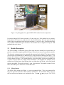
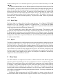
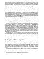
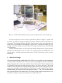
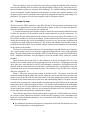
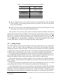
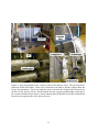
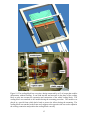
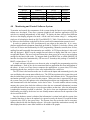
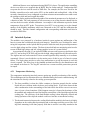
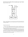
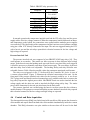
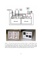
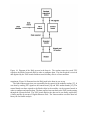
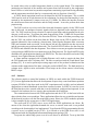
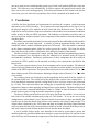
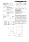
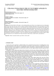
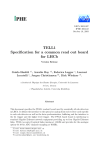
Department of Physics & Astronomy
Experimental Particle Physics Group
GLAS-PPE/2007-08
7 July 2007
Kelvin Building, University of Glasgow,
Glasgow, G12 8QQ, Scotland
Telephone: +44 (0)141 339 8855 Fax: +44 (0)141 330 5881
A facility for long term evaluation and quality assurance of LHCb Vertex
Detector modules
F Marinho , A Bates , R Dimattia , F Doherty , R Dumps , M Gersabeck ,
J Melone , C Parkes , A Saavedra
, M Tobin
* Corresponding authors
The University of Glasgow, Dept. of Physics and Astronomy
European Laboratory for Particle Physics (CERN)
University of Liverpool, Dept. of Physics
Now at Sidney University, NSW, Australia
Abstract
This note describes the facility developed for long term evaluation and quality assurance of the LHCb Vertex Detector modules, known as the ‘Glasgow Burn-in System’. This
facility was developed to ensure that the modules conform to stringent quality levels. The
system was able to uncover any weaknesses that could be introduced during the manufacturing and assembly of the components or during the transport of the modules to CERN.
The system consisted of: a high resolution microscope for visual inspections; and a burn-in
system to operate cooled modules in vaccuum. The main components of the burn-in system
were a vacuum system, a cooling system and a DAQ system.
1 Introduction
The aim of this note is to describe the system developed to exercise LHCb VELO modules under
realistic conditions for long periods of time. This is colloquially referred to as the burn-in of
the module. The aim of the Glasgow burn-in system is to uncover any weaknesses introduced
into the modules during manufacturing or in the components themselves. The system is able to
verify that all the modules which are tested conform to a certain level of quality.
The LHCb modules were produced at Liverpool and then transported to CERN where they
were received, visual inspected and tested in the burn-in setup. This document is divided into a
number of sections detailing these tests and describing each sub-system’s purpose, construction
and performance. An overview of the laboratory area and discussion of the tests performed is
given in Section 2. The different aims of these tests are also explained. Section 3 describes the
hardware equipment used on the reception and visual inspection in more detail. It also lists all
the items verified on the modules. Section 4 describes the burn-in setup and its components.
Each of the burn-in components is described in separate sub-sections of Section 4 where
details on the construction and performance are given. The burn-in sub-systems were used
together to replicate the environmental conditions of the experiment and to operate the modules.
Section 5 concludes the report by providing an overview of the performance of the system and
commenting on how the environmental conditions of the experiment were replicated.
The analysis and results obtained on the testing of the modules in the burn-in facility are
presented in a second note [1].
1.1 LHCb
The LHCb detector [2] is an experiment primarily designed to study CP violation and rare
decays studies in the -hadron sector. It is essential for these investigations that the detector
reconstructs the particle tracks to a great precision inside its volume and locates the primary
interaction and decay vertices. The vertex reconstruction is performed by the Vertex Locator of
the experiment.
The detector was designed to reconstruct the position of the vertices with high precision.
For primary vertices the resolution is about 42 in the beam direction ( axis) and 10 in the transverse plane ( plane). Such measurements are necessary for accurate calculations
of the lifetime and impact parameter of the -hadrons. The resolution for decay length ranges
from 220 to 330 depending on the decay process of interest. An impact parameter
resolution of 20 is expected for those tracks with higher values of transverse momentum ( 10 GeV/c).
1.2 Vertex Locator
For this experiment the VErtex LOcator (VELO) [3] plays an important role. It will make
precise measurements of the coordinates of the tracks close to the interaction region. The VELO
covers not only the angular aperture of the LHCb spectrometer but also has limited coverage in
the opposite hemisphere. Using these measurements it is possible to determine the position of
the primary and secondary vertices in the observed events.
The VELO system is composed of a series of silicon detectors stations placed along the
beam direction. There are two halves of the VELO detector. Each half contains 21 modules.
The nominal distance of the sensors to the beam during operation will be 7mm. The halves can
1
Figure 1: A photograph of a
glued LHCb VELO module and its components.
be retracted during LHC beam injection by 30 mm each side. Each module has two sensors
back to back. The sensors are strip detectors with a half disk shape. The strip pattern depends
on the kind of measurement that the sensor performs. It can be an R or measurement and
every module contain both types of sensors. The modules have an angular coverage of 182 perpendicular to the beam.
1.3 Module Description
The VELO module is composed of two silicon strip detectors attached on a hybrid which is
glued to a carbon fibre support paddle [4]. Figure 1 shows the sensor of a production module.
The electronic components are also mounted and connected on the hybrid. The charge readout
of each sensor is performed by 16 Beetle chips [5] whose location is indicated in Figure 1. The
kapton cable connectors and negative temperature coefficient thermistors (NTCs) on the hybrid
are also shown in Figure 1. The cooling interface, where the hybrid is glued to the paddle, has
5 captive screws to allow the cooling cookies attachment. For simplicity the modules can be
referred to as R glued or glued because they can either have the R or side of the hybrid
glued to the paddle. The module in figure 1 is a glued module. The paddle is made of a low
mass carbon fibre piece attached to a carbon fibre base.
1.3.1 Silicon Sensors
The LHCb VELO sensors are 300 n -on-n oxygenated silicon. They were optimised for
long term operation under the LHCb radiation environment. The maximum fluence rates on
this non-uniform environment were estimated to be 1.3 per year. The VELO
2
module should operate over a minimum period of 3 years at the nominal luminosity of 2 10 cm s .
As already mentioned there are two different patterns of strips on the silicon sensors of the
VELO modules. The strips on the R sensors have annular shape with length increasing from 4.0
mm to 34.0 mm from the innermost region to the outermost region respectively. The inner-strip
pitch size varies from 40 m to 92 m. The strips are set in an arrangement of 4 sectors. Each
sector has the same size and contains the same number of strips. The strips on the sensors
have a radial geometry and are divided in inner and outer strips. The length of the inner and
outer strips are 9.3 mm and 24.9 mm respectively. The pitch size on the sensors vary between
37 and 98 .
1.3.2 Beetle Chips
The Beetle chip is a readout device for silicon strip detectors. It is a Bipolar CMOS ASIC
fabricated in 0.25 technology designed to be radiation hard. It will operate in 40MHz
analogue readout mode and trigger rates up to 1.1 MHz can be sustained. Technical details on
design requirements and specifications are found at [5].
The VELO module has a total of 4096 strips, with 2048 per sensor. The signals are read
out from the strips using Beetle front-end chips. Each Beetle chip reads out 128 strips, hence
32 Beetle chips are necessary to read out the module, with 16 chips per sensor. One single
Beetle chip has its readout channels arranged in a set of four ports on the readout multiplexing
analogue mode. Therefore one port has 32 channels. In total 1344 chips will be operated on the
42 modules of the VELO.
1.3.3 Hybrid
The hybrid is implemented as a flexible kapton circuit which encapsulates a substrate to provide
apropriate thermal conductivity to allow the removal of the heat from the front-end and sensors.
The hybrid bulk is an Thermal Pirolytic Graphite substrate (TPG) wrapped by layers of carbon
fibre to provide it with strength and for safe handling. The main purpose of the hybrid of the
VELO module is to provide electronic support for the sensors. The electronic components such
as kapton connectors, thermistors, Beetle chips, pitch adaptors are mounted onto the hybrid.
The bias voltage is also supplied to the sensors via the hybrid. In addition it mechanically
supports the sensors and minimises material.
2 Overview
The VELO modules are comprised of a number of different materials with different physical
properties and the functionality of the active components need to be tested under long term
operation. For example latent defects can be hidden in its components or be introduced during
its assembly. Any dynamic component can also suffer from infant mortality which refers to
the malfunction of the component after a short time of operation. The long term testing and
stressing under realistic environmental conditions is one way to detect faulty components that
can result in the compromise of the long term operation of the unit. The faulty components can
then be fixed or replaced.
Verifying the long term operation of each VELO module is a primary concern due to the
harsh and inaccessible environment that it operates in and the loss of coverage the vertex de3
tector could suffer as a result of a malfunctioning unit. The main aspects to be covered by the
long term stressing are the operation under vacuum, the temperature cycling the module will
be subjected to and any infant mortality that the electronic components may suffer. A number
of guidelines have been developed from experience to perform long term testing that results in
improving the long term operation of the unit. Documents [6, 7] describe guidelines for similar
applications, these were used in determining the procedure for the VELO module tests.
The other aspect that can affect the long term operation of a module is any physical damage
that the module could suffer due to handling at the assembly stage, during transportation or testing. The damage can range from subtle effects such as misshaped wire bonds to serious damage
such as chipped or scratched silicon sensors. The modules were transported from Liverpool,
the assembly site, to Geneva where they were integrated into the VELO detector. The modules
were received at the Glasgow test facility at CERN using procedures designed to verify the integrity and quality of the delivered modules . These tests consisted of a visual inspection using
a high resolution microscope and a burn-in procedure.
The aim of the inspection was to verify the physical integrity of the module after transportation. It consisted of a high resolution visual inspection over all the bonds, components and
silicon on both sides of the module for any visual signs of damage. Electronic components were
verified. Photographs of the modules may be taken for later analysis if necessary. The kapton
cables were shipped with its corresponding module and were also inspected.
The burn-in system was used to perform a series of tests to stress the modules when functioning in similar conditions to its normal operation in the experiment. It has been built to
perform periodic thermal cycles while the modules are operated as in the real experiment. To
reproduce such conditions the modules have to be enclosed in a vacuum chamber and its temperature must be controlled by a cooling system. The module was powered on and its front-end
readout chips were exercised by providing a clock, commands and triggers. Figure 2 shows
a diagram to illustrate the burn-in setup. It was composed of a vacuum system, cooling system, interlocks, DAQ system, low voltage supplies, high voltage supply and two PCs to control,
monitor and perform data analysis.
The photo in Figure 3 shows the laboratory where the modules arrived and the burn-in took
place from a number of angles. The pictures shows the whole setup from the left and from the
right side. On the left side the visual inspection microscope, the data analysis PCs and the DAQ
hardware are shown. On the right side the cooling system, the vacuum system and reception
area are shown.
3 Reception and Visual Inspection
The VELO modules on arrival from Liverpool university underwent the module reception procedure. A check list was followed to verify if any visible problem could have happened during the transportation. This reception procedure included a check on the clamps, feet, captive
screws, paddle, cooling face, hybrid, bond wires, chips and silicon. The integrity of the module’s kapton cables and respective clamps were also verified. These components are shown in
Figure 1 .
A high-resolution visual inspection was done with a Lynx microscope equipped with camera. Photos were taken for further analysis. For the inspection a module is mounted in an
aluminium frame with clear plastic covers on both sides. Figure 4 shows the visual inspection
A transportation box was developed for the transportation of the modules [8]
4
Figure 2: The burn-in setup is composed of vacuum system, cooling system, interlocks, DAQ
system, low voltage supplies, high voltage supply and 2 PCs to control, monitor and perform
data analysis.
Figure 3: The burn-in area layout. On the left side the visual inspection microscope, the data
analysis PCs and the DAQ hardware are shown. On the right side the cooling system, the
vacuum system and reception area are shown.
5
Figure 4: A Lynx microscope equipped with coolpix camera is used to perform the visual
inspections. On the left side a module is mounted on the visual inspection frame. Various items
are verified on the visual inspection. Problems as the lifted bonds and defects on the pitch
adaptors seen on the right-hand side picture are typical problems that can be found during the
visual inspection.
setup. It consisted of fine integrity verification of all the module components. Some examples
of typical problems that can be found with the microscope such as lifted bonds and defects on
the pitch adaptors are also shown in Figure 4.
After the completion of the burn-in test a second visual inspection was done in order to
verify if any changes have happened during the period of tests.
3.1 Module Handling
An important aspect of the system was enabling the safe handling of a VELO module throughout the different stages of testing. A frame was designed to incorporate the following points, as
well as being compatible with the burn-in setup:
Easy and safe mounting and dismounting of modules to the frame.
Thin enough for the module to be placed underneath the visual inspection microscope.
Allow access to either the
burn-in.
and
faces of the module during visual inspection and
A mounting system compatible with the standard connections on the feet of the module
to minimise unnecessary stresses.
6
Figure 5: An LHCb VELO Module mounted in the mechanical frame on the transfer jig.
The frame designed to meet all of these requirements is shown in Figure 5 together with
the transfer jig. The transfer jig was employed to transfer modules to and from the frame in a
safe manner. The diagram shows how the sides of module frame can be removed allowing the
module to be easily mounted or dismounted on its base as it is held by the transfer jig. The
and faces of the module were protected by clear plastic panels that were removed during
visual inspection.
A similar aluminium frame was used to place the modules into the burn-in vacuum chamber.
It had the same dimensions as the one used on the visual inspection but modifications were
made in order to satisfy the mechanical requirements. Details on the burn-in system are given
in Section 4.
4 Burn-in Setup
The most important design consideration of the VELO was to optimise the impact parameter
resolution of the reconstructed tracks. This was achieved by keeping the material to a minimum
and by placing the sensors as close as possible to the interaction point. The first condition results
in the modules being operated under vacuum in order to get close to the beam. The second
condition results in high levels of radiation being incident on the sensors during operation. The
sensors were designed to withstand high levels of radiation. In order to minimise the effects of
radiation damage the sensors are kept at temperatures around -5 / -7 C. This condition implies
that during the lifetime of the modules they will undergo a large number of temperature cycles
as either the cooling or its front end electronics are switched on or off.
7
These two features were recreated in the burn-in by operating the modules inside a stainless
steel vacuum chamber while in contact to an internal liquid cooling circuit. Achieving the vacuum and module cooling was only part of the challenge. The module handling, the monitoring
of the environment, module parameters and interlocks to ensure safe module operation were
all aspects of the burn-in system that also required development for the long term testing to be
performed. The purpose of each system together with its description follows.
4.1 Vacuum System
The burn-in of the LHCb modules is only fully effective if the operational environment in the
experiment is approximately recreated during testing. Hence, in order to evaluate the functioning of the modules a vacuum system was constructed.
A vacuum environment was needed not only to mimic the experimental conditions but also
to allow the operation of the modules with the same parameters as on the experiment. To
safely apply the bias voltage default on the sensors it was necessary to have the module at very
low pressure condition to avoid any discharge. Studies performed on the burn-in system have
shown that discharges don’t occur at atmospheric pressure or very low pressure conditions but
a mid-pressure range should be avoided [9]. The heating and cooling of the module could be
performed when the module was in vacuum with no concerns of the formation of condensation
on the surface of the module.
The burn-in vacuum system consisted of a vacuum pump setup and stainless steel chamber.
The vacuum pump system is based on the traditional arrangement of rotary pump and turbo
pump. The turbo pump model was a Pfeiffer TPH 330 and the rotary pump was a Pfeiffer DUO
012A. Additional mechanics were developed to locate the module safely inside the vacuum
chamber.
Figure 6 shows the vacuum tank. Its has a diameter of 40 cm and length of 60 cm. Connection to the vacuum system was done through the back of the tank. A diaphragm valve and
an air inlet valve were attached in a 40-25 mm reducing tee connection, which allows air to be
released inside the tank when tests were finished. A 40 mm ball valve was installed to close the
connection between the vacuum pumps and tank. The diameter of the flexible hose is 40 mm
and it has a length of 1 m.
Figure 7 shows the vacuum pump system in the burn-in lab. The picture at the left side
shows the pumps inside the plastic box used to isolate the system from the clean room since the
pumps were not rated for class 100,000 clean rooms. The rotary pump had its exhaust connected
to outside of the clean room because of the toxic and contaminating nature of its gases. In order
to avoid any oil reaching the vacuum chamber a foreline trap was placed between the rotary and
turbo pump. In the centre photograph in Figure 7, the header vessel mounted on the turbo pump
is shown. It has one 25 mm connection to a vacuum pressure reading penning gauge and four
40 mm connections available. One was used to attach the flexible hose to the vacuum chamber.
On the right hand side picture the control panel is shown.
To provide the appropriate vacuum environment to operate the VELO modules any leak on
the vacuum system connections should be avoided and the outgasing of the components used
inside the vacuum should be minimised. A set of measures were taken in order to achieve the
desired vacuum quality.
The additional mechanics and electronic components used inside the chamber were suitable for high quality vacuum applications.
8
Figure 6: Picture of the stainless steel vacuum tank. Its dimensions are 40 cm diameter and 60
cm length. The tubing has 40 mm diameter and a 1 m length. A set of valves were installed to
facilitate the vacuum operation procedures.
Figure 7: Three photographs showing the vacuum pump system. The left hand photograph
shows both pumps and their respective accessories. The centre photograph shows the turbo
pump and its connections. The right hand photograph shows the control panel.
9
Table 1: The specification parameters for the Chiller.
-40 C - +200 C
50 W at -40 C
200 W at -30 C
Heating power
1.5 kW
Maximum power
2.5 kW
Control Interface
RS232/RS485 via CC3
Tubing connections
male M16x1
Temperature range
Cooling power
All the mechanics pieces were properly cleaned in a ultrasound bath, dried and baked
before assembly. This cleaning procedure has been repeated a few times for the plastic
pieces of the mechanics.
Gloves were always used when handling anything that was to be placed inside the vacuum
and measures were taken to keep the vacuum tank clean.
The operation of the vacuum system with its mechanics inside the chamber has achieved
appropriated vacuum quality and stability. The rotary pump sustained the secondary vacuum at
levels of 0.1 Torr after 10 minutes of operation. The turbo pump reached levels of 5-10 10 mbar after 20-40 minutes of operation on the primary vacuum. Pressure values of the order of
0.5-1.0 10 mbar were obtained after overnight runs. No quality degradation of the vacuum
or turbo pump failures was observed during the assembly and test phases.
4.2 Cooling System
The VELO cooling system has been designed to keep the silicon detectors in a temperature
range of -7.0 C to -5.0 C while the temperature of the Beetle chips and other electronics
components should be kept below 40 C. To mimic the environment in the LHCb experiment
a cooling system was set up in the burn-in lab. It was meant to control the temperature of the
modules and to perform thermal cycles in order to stress them thermally and mechanically.
The cooling system developed for the burn-in consisted of a chiller, insulated hoses, cryogenic feedthroughs, flexible metallic hoses and a custom designed cooling block that was attached to the module. Figure 8 shows some pictures of the burn-in cooling system.
The thermal control was provided by Huber CC415 circulator [10] controlled through a
RS232 interface. The parameters of the chiller that suited the needs of the burn-in system are
shown in Table 1.
In order to avoid moisture condensation on the bath surroundings the reservoir was sealed
and a nitrogen flow of about 4.5 l/h was used to keep the internal environment dry.
The coolant liquid used is a low viscosity silica oil also provided by Huber . Its relevant
properties for the burn-in operation extracted from the safety data sheet are listed in Table 2. The
liquid was cycled in the temperature range between -37.0 C and 30.0 C. All safety measures
for handling were followed when evacuating the bath container or replacing the thermo fluid.
The silica coolant type used in the burn-in was SilOil M60.115.05. Its specifications and safety data sheet can
be found at [11].
10
Figure 8: Four photographs of the cooling system in the burn-in setup. The top left picture
shows the chiller front panel. Tubes were connected to the bath to provide nitrogen flow and
keep a dry atmosphere. On the top right the hoses to conduct the coolant liquid connected at
the back of the unit are shown. On the bottom left the cryogenic feedthroughs connected to
the vacuum chamber lid are shown. On the bottom right the flexible hoses and cooling block
located on the opposite side of the lid can be seen.
11
Table 2: Silica coolant liquid specification parameters.
Boiling point
300 C at 1013 mbar
Density
0.923 g/cm at 25 C
Vapour pressure
0.01 mbar at 20 C
Kinematic viscosity
5 mm /s at 25 C
Heat capacity
1.63 J/(g K)
Thermal conductivity
0,133 W/(K m)
Solubility in water
insoluble
Flash point(DIN 51376)
120 C
400 C
Ignition temperature (DIN 51794)
The unit does possess a number of hardware alarms such as low or high fluid level in its
bath, overheating and malfunctioning. Given the small volume of coolant liquid necessary
and temperature requirements for the burn-in operation it was possible to set all the safety
parameters to values even more stringent than those proposed by the manufacturer. These values
were also chosen in order to fully satisfy the coolant specifications. In the situation where one
of these hardware alarms was triggered the chiller unit turns off its cooling and stops pumping
the coolant liquid through the cooling system. If the module was to over heat after a cooling
system failure then the burn-in interlock system is triggered and the module voltage supplies
are turned off. More details on the burn-in interlock system are discussed on Section 4.5.
The coolant was conducted to the vacuum chamber via insulated hoses that were connected
to the cryogenic feedthroughs on the lid of the vacuum chamber. The feedthroughs make the
connection between the external part of the cooling system and the flexible metallic hoses attached to the cooling block inside the vacuum chamber. The cryogenic feedthroughs were
required to minimise the thermal conductivity between the hoses carrying the coolant and the
chamber lid.
Two triple insulated hoses of 1.5 m length were the most appropriate tubing choice to conduct the coolant from the chiller to the vacuum chamber. The hosing operational temperature
range is between -100.0 C and 200.0 C. The fittings are female M16 1. External and internal
diameters are respectively 42 mm and 10 mm. The insulating layers used are glass silk (3 mm
thick), silicon foam tubing (6 mm thick) and a black poly braiding cover. An external layer
of rubber insulation was also added to the tubes in order to reduce the heat loss as much as
possible.
To connect the hoses to the swagelock fittings of the tube of the cryogenic feedthroughs a
M16X1 to 3/8 inches adaptor was installed between them. The feedthroughs were connected
to flexible metallic hoses inside the chamber with swagelock fittings. The flexible hoses can be
bent with a minimum radius of 4.0 cm in dynamic applications. In the burn-in system the radius
was estimated to be bigger than 5.0 cm and it is a quasi-static application. On the other extreme
of the flexible hoses, the cooling block was attached as shown in Figure 9. The length of the
tubes has been chosen such that low stress was applied to the cooling block. The curved shape
of the hoses was designed such that the cooling block was not pushed against the module. In
fact, it tends to bring the cooling block to the lid direction.
The cooling block was the part of the cooling circuit that was attached to the module cooling face to provide the actual removal of the heat from the module to the coolant liquid that
12
Figure 9: The flexible hoses were connected on the feedthroughs and cooling block. The length
of the tubes has been chosen such that low stress was applied to the cooling block. The curved
shape of the hoses was such that the cooling block was not pushed against the module.
circulates inside it. Its mechanical design satisfies the following set of requirements:
The thermal interface between the cooling block and the module should be such that no
mechanical stress is applied to the module.
The cooling block shape must maximise the contact area with the module cooling face.
The cooling block should fit in the 5 mm gap between the module cooling face and the
kapton cables.
If the displacement of the paddle or hybrid with respect to its original position is of the order
of 100 m it could cause a permanent deformation and therefore a systematic misalignment of
the module. It could also damage the hybrid and/or the sensors.
The second item directly affects the performance of the cooling system to remove heat from
the module. The size of the contact surface of the cooling block was mainly limited by the
area of the module thermal interface. The size of the cooling block was also constrained by the
distance between the module kapton cables and the module thermal interface. Figure 10 shows
a 3D diagram of the cooling block attached on a module mounted on the burn-in frame.
The cooling block was composed of a copper pipe and two aluminium blocks as indicated
in Figure 10. The aluminium pieces make the connection between the metallic flexible tubes
and the copper pipe closing the circuit where the coolant liquid flows inside. The design of the
cooling pipe with two flat pieces connected by a cooper U allows the block to slightly deform
due to temperature variations without applying any mechanical stress on the module. The two
copper flat pieces were made of 6 mm copper blocks machined out and lids attached with high
13
temperature braising. This avoided any leaks while operating at low pressure. Thermal film
COH-4000 with 0.5 mm thickness was used as a thermal interface to attach the copper pipe
to the module cooling face. The film interface improves the thermal connection filling the
small gaps due to the cooling block surface irregularities. Its low outgassing properties were
compatible with the system. Figure 10 shows the cooling block installed on the chamber lid
and also attached to one of the modules. The module was placed in the burn-in frame which
had a hood to protect the silicon sensors during the procedure. The burn-in frame sits in a
plastic cantilever attached to the vacuum chamber lid. This plastic piece is suitable for vacuum
applications and prevents heat flow from the lid to the frame. The cooling block was attached to
the frame using plastic L shapes to reduce the heat flow from the frame to the cooling block. A
support at the opposite side was used to attach the cooling connection and position the cooling
block correctly. Additional clamps were attached to the flexible tubes to avoid the mechanical
stresses that could happen due to thermal expansions or contractions during the temperature
cycles.
To achieve the required temperature for the thermal cycling, the circulator was operated
at -38 C. The cooling block temperature at this point achieves a minimum of -30 C with
and without a module mounted. No significant temperature difference was observed when the
module low voltage was switched off. The minimum temperature measured on the hybrid with
the readout electronics off was between -20 C to -25 C showing that the cooling system was
capable of thermally stress the modules. The cooling system was able to vary the temperature of
the module hybrid from 30 C to its minimum in about 20 minutes. It allows the burn-in system
to thermal cycle the modules in temperature ranges compatible to those in the experiment.
4.3 Voltage Supplies and Monitoring Devices
There are a number of voltages that are required by the VELO module to be fully operated.
For nominal operation a module requires 24.5 W. A set of electronics devices were used to
supply the electronics with appropriate voltages, currents and to read out the NTCs mounted on
the modules hybrid, repeater boards, cooling block and vacuum chamber walls. To supply the
modules with low voltage and high voltage two component units were used.
An Agilent E364BA was employed to supply two channels for the module low voltage.
Each channel was used to supply 16 Beetle chips on each side of the module. Each Beetle chip
was powered with 3.5 V and consumes 0.22 A.
An 8 channel Iseg GCH224L unit provided the bias voltage to deplete the module sensors.
Each sensor was biased by an individual channel.
The voltages were supplied to the module via the repeater boards. The repeater boards are
the components of the burn-in DAQ which not only serve the modules with the voltages but
also drive and amplify the read out signals. More details on the DAQ electronics on the burn-in
is given in Section 4.5.
A second Agilent E364BA was also used to power the repeater boards themselves. A channel was available on each of the two repeater boards used. To monitor the NTCs on the modules hybrid, repeater boards, cooling block and vacuum chamber walls a Keithley multimeter
equipped with two cards of 20 and 40 channels was used. The resistances of the NTCs were
measured and the temperatures were calculated using the manufacturer’s calibration formulas.
The Iseg unit and the Keithley multimeter were controlled by the software suite described in
Section 4.4.
14
Figure 10: The cooling block has a two piece design connected by an U of cooper that enables
deformation without buckling. It can bend inwards and outwards in the plane of the cooling
block to take into account the expansion and contraction of the whole cooling block. The
cooling block was attached to the module during the mounting procedure. The module was
placed in a special frame which had a hood to protect the silicon during the mounting. The
cooling block was attached to the frame and a support at the opposite side was used to optimise
the cooling connection and position the cooling block correctly.
15
Table 3: List of devices, drivers and protocols in the monitoring software.
Device
Chiller Huber
Keithley
Agilent
Iseg
Function
Driver
Protocol
Module cooling
QextSerialPort 0.9 RS232
NTCs monitoring
linux-gpib-3.1.101
GPIB
Hybrid low voltage linux-gpib-3.1.101
GPIB
Sensors high voltage
pcan-usb
USB
4.4 Monitoring and Control Software System
To monitor and control the components of the system during the burn-in tests software algorithms were developed. There was a separate graphical user interface application (GUI) for
each device running independently of the others. To display the data read out from different
devices a data display program was made. All the code was written using C++ coding and a
single set of technologies based on Qt[12] and ROOT[13]. Table 3 lists the devices controlled
by software, their function on the burn-in, driver names and communication protocols used.
In order to optimise the GUI development Qt was taken as the main tool. It is a crossplatform application development framework provided by Trolltech. It includes a library with
a rich set of classes and functionality for GUI programming. Manuals, tutorials, how-to lists,
mailing lists and brownsable documentation are available. A GUI layout designer is also available (Qt designer). ROOT was the straight forward choice to display data and save it into a
recognisable format. This set of tools and classes have been proven to be easy to use and robust
enough for the burn-in lab needs. To integrate both Qt and ROOT the so called QtROOT[14]
interface developed and maintained by GSI was used. Nowadays this package is available in
ROOT versions above 5.11-02.
A simple software architecture was chosen in order to simplify the programming activities
and maintenance. Each of the devices mentioned had an application that runs independent of
the others. A basic set of four classes composes the applications: a system class; GUI class;
monitoring thread class; and device class were implemented for each device.
The GUI class is the interface to the user. It reads out the inputs and commands given by the
user and displays the current status of the device. The GUI has a pointer to the system class such
that the instructions given by the user can be delivered to the hardware device. The signal/slots
mechanism provided by Qt is used for this purpose. When an action is requested by the user
the system class gives the updates to the monitoring thread that runs independent of the GUI
and communicates with the hardware via the device class. To avoid conflicts when accessing
memory the system class locks the addresses where the new command information is written
to disable the thread from trying to access the same address at that time. After the information
is updated the memory location is unlocked. The device class was implemented with all the
functionality provided by the drivers in a user friendly manner and tuned to the operation of the
devices used in the lab.
Once the hardware status is obtained the information is written back and the system class
is notified that there is data to be updated via a posted event by the thread. If required the data
is passed to the GUI by the system class. The System class also writes the data in a memory
address shared with the data display software. It uses the signal/slots mechanism to notify the
data display that there is more data available to be added to the graphs.
16
Additional features were implemented using ROOT I/O classes. The application controlling
devices were able to save acquired data in ROOT files for further analysis. Configuration files
to operate the devices could be saved in XML files. For example, the files were saved for the
Keithley controller used to read out the NTCs on the module and cooling block. After all the
necessary channels used were configured to perform resistance measurements one could record
the settings on disk and load it again afterwards.
The data display application allowed graphs of the monitored parameters to be displayed as
a function of time. For each parameter it was neccessary to set up the eletronic channel used to
read out the device and a suitable calibration. An example is the calibration required to obtain
temperatures from an NTC probe. To monitor a given NTC it was necessary to set the channel
number of the Keithley multimeter which was connected to the NTC and the calibration that
should be used. Then the channel configuration and corresponding calibration could also be
recorded in XML files.
4.5 Interlock System
The modules were protected by a hardware interlock system against any malfunction of the
burn-in system that could harm their physical integrity. Interlocks were developed for monitoring the temperature on the hybrid and the pressure inside the tank, the protected parameters
were the high voltage and low voltage. The burn-in interlock had two monitoring units in order
to turn off both high voltage and low voltage supplies in case of a system failure.
As mentioned in Section 4.3, an Agilent E364BA unit was used to power up the Beetle chips
with 3.5V and an Iseg GCH 224L unit provide the high voltage applied to the silicon detectors.
The Agilent unit can not be turned off via an external signal but only manually or via software
commands. Hence it was decided to cut the mains power of this in case of a burn-in system
failure. The high voltage unit has a safety loop mechanism to cut off the outputs in case this
circuit is opened. The safety loop is the standard mechanism offered by the manufacturer and
was adopted in the burn-in. The Iseg HV unit also has a current overflow protection system in
its output.
4.5.1 Temperature Monitoring
The temperatute monitoring interlock protects against any possible overheating of the module.
This could happen in four situations that were identified during the burn-in commissioning. All
the situations are directly related to the cooling system operation.
1. The first possibility is when the chiller continues to function properly but the coolant
liquid does not circulate inside the hoses and cooling block. It has been observed that
water condensation in the surroundings of the bath inside the chiller reservoir can occur
since it is not a closed container. If this happens some ice is formed in the mixture of the
thermofluid and condensed water blocking the normal flow of the liquid through the thin
cooling pipe. The efficiency of the final module cooling is then drastically reduced and
during operation of the chips the module could over heat due to insufficient cooling.
2. The thermal connection between the cooling block and the module in the burn-in is highly
dependent on the cooling block positioning and overheating could also occur if the cooling block mounting is not done properly such that its surface is not fully attached to the
17
module thermal interface. However, this problem would be rectified since it would be noticed and corrected during the start up of the burn-in procedures and before the interlock
being triggered.
3. The third situation is when the chiller mains could be turned off due to the chiller drawing more power than that specified as maximum for operation or due to the mains fuse
blocking if the drawn current is too high. The maximum current allowed in a standard
fuse for mains is 10 A and the maximum current operation of the chiller is 11.5 A.
4. Human error could also lead the interlock system to trigger if the module is turned on
with the cooling system off or set up to run in a non safe temperature level.
In each of these three scenarios, the module temperature would rise and at a hybrid temperature
of 50 C both the low voltage and high voltage would be turned off, thereby reducing the
temperature of the module.
4.5.2 Pressure Monitoring
Monitoring of the pressure was necessary since a vacuum system failure could cause a raise in
the pressure inside the chamber while the module was operated in high voltage and at low temperature conditions. In this case condensation could occur over the silicon surface and electronic
components of the modules if they were operated at low temperatures in an air environment.
The pressure level for operation of the high voltage applied on the silicon sensors is not yet
well defined but the pressure value of 1 10 mbar was set as a minimum value for the safe
operation of the modules above 100 V in the burn-in.
The Controller 201 unit in the vacuum system provided a set of 3 output relays. Two of
them gives one output (ON/OFF) and the third provides two outputs (ON/OFF & OFF/ON). A
voltage of 5 V was connected to one of the relays in order to provide a step signal in case the
pressure goes above a certain threshold range of pressure. A few situations where the pressure
interlock system should take action were identified during the burn-in setup commissioning. All
were directly related with the functioning of the vacuum pumps since all the potential air leaks
were eliminated during the burn-in commissioning.
The most probable is when the power supply of the vacuum system is off due to excessive
power demands. In this case the relays in the pressure interlock system are triggered immediately and not when the pressure reaches the maximum pressure level allowed for operation. The
relays are used to interrupt the power supply to the high voltage and low voltage systems, as
described below.
The less probable cases would be of proper degradation of the vacuum making the turbo
pump turn itself off. This could happen due to outgassing of the plastic arm that supports the
module frame or, for example, some small piece of kapton tape that could be released and
dragged into the vacuum tube causing a blockage. In these cases, since the gauge unit was
completely independent of the turbo pump, the relays would change their state if the pressure
readings passed the maximum level allowed.
4.5.3 Interlock Unit Devices
The burn-in system had two independent devices to protect the modules in case of failure, which
were a temperature unit and a pressure unit. They worked in a series arrangement such that the
18
high voltage and low voltage supplies would be turned off both in the case of the temperature
passed certain limits or the pressure was bove the acceptable threshold. Figure 11 shows a
diagram of the interlock system.
Figure 11: Interlock diagram. It uses two units to protect the module inside the chamber. The
arrangement of the interlock units ensure that high voltage and low voltage will be turned off in
case of a system failure.
Temperature Interlock Unit
To protect the system against overheating accidents a temperature monitoring device was
built. It uses a regulator CAREL IR32 [15] with a resistance input. It is simple to program and
has a set of prearranged functions that allow operation in different modes, parameter values and
calibration offsets. Figure 12 illustrates how the unit was set.
The front panel of the unit shows the current hybrid temperature and the working parameters
were set on the front panel. The temperature was obtained by converting from the resistance
read on the NTC on the module. The resistance input connectors were also located at the front
panel of the unit. At the back of the device a set of two 230 V plugs (INPUT/OUTPUT) and 2
banana plugs (INPUT/OUTPUT) were available to connect the Agilent and Iseg devices. The
unit supply cable was also connected at the back.
19
Figure 12: Temperature interlock schematic and pictures of the unit. The input signal was the
resistance read from one NTC on the hybrid. The current temperature was shown in the front
panel display. The unit used two relays to interlock both high voltage and low voltage units.
On the back panel the HV safety loop and Agilent power cable were connected. If a module
overheats both connections are opened and the module power supplies are turned off.
20
Table 4: BROICE relay parameters list.
Parameter
Input voltage range
Over voltage
Hysteresis
Time delay
Reset time
Latching facility
Relay inversion
Values
0.5 - 10.0 V
3.0 - 60.0 V
30.0 - 600.0 V
0 - 100%
5 - 50%
0.1 - 3 s
60 ms
selectable
selectable
In normal operation the temperature interlock unit had the HV safety loop and the power
supply cables of the low voltage connected. When the temperature interlock detected an abnormal temperature on the hybrid, the connections were opened and the modules power supplies
were turned off. The functioning of the temperature interlock unit was tested without a module
using just a 10k NTC directly connected to the input. The unit was triggered heating the NTC
with a hot air gun and the unit relays opened their electrical contacts for the low voltage and
high voltage as expected.
Pressure Interlock Unit
The pressure interlock unit was composed of two BROICE 45050 unit relays [16]. They
could operate in two modes. This model was able to operate in three different input voltage
ranges. In the burn-in setup the latching mode was used in such a way that if they were triggered
it would be necessary to manually turn them off and restart again. The overvoltage, hysteresis
and time delay from a fault were adjustable. The latching facility and relay inversion were
selectable features. Table 4 lists the possible values the parameters mentioned could assume.
The relays were triggered via the 5 V delivered by the Controller 201 device in case of
a vacuum system failure. Figure 13 illustrates the electrical connections of the unit. On the
front panel of the pressure interlock unit values for the hysteresis could be set. A set of two
230 V plugs (male and female) and two banana plugs were available at the back to connect the
Iseg safety loop and the Agilent power cable. One BROICE unit was used to interlock the low
voltage supply and the other was used to interlock the High voltage safety loop. The mains
power cable connection for the unit was also located at the back panel.
The pressure interlock was verified using the burn-in vacuum system but also without a
module mounted. The pumps were turned off and the pressure hardware interlock relays opened
their electrical contacts for the low voltage and high voltage as expected.
4.6 Control and Data Acquisition
The data acquisition setup (DAQ) used in the burn-in lab was able to fully operate the electronics
of the module and acquire data from both sides of the module simultaneously inside the vacuum
chamber. This DAQ electronics was quite similar to the ones that will be used in the final
21
Figure 13: The top picture shows the pressure interlock schematic. The input signal was the
0-5 V delivered by the Controller 201 unit in the vacuum pump system. It used two relays
to interlock both high voltage and low voltage units. The state of the relays can be verified
from the LEDs on the front panel. The overvoltage and hysteresis are tuned on the front panel
buttons. On the back panel the HV safety loop and Agilent power cable are connected.
22
Figure 14: Diagram of the DAQ system in the burn-in. The readout supervisor sends TFC
signals to the Beetle front-end chips in order to configure them. The data acquired is received
and digitised by the Tell1 boards and then stored in binary files in a Linux machine.
experiment. Figure 14 illustrates how the DAQ used in the burn-in was set up.
The Odin readout supervisor was responsible for the control of the modules readout [17]. It
was done by sending TFC signals to the control board [18] and Tell1 mother boards [19]. The
control board sent these signals to the Beetle chips in the modules via the repeater boards in
order to configure and operate them. The data acquired was sent back to the Tell1 boards passing
through the repeater boards. The Tell1 boards digitise the data and it was finally acquired by
a Linux machine by means of Gigabit Ethernet cards. The Linux machine saved the data in a
binary file for further analysis.
23
Figure 15: The DAQ setup in the burn-in system.
4.6.1 Data Readout
The DAQ hardware consists of two Tell1 mother boards, two repeater boards, one control board
and one Odin readout supervisor. The Tell1 mother boards, control board and readout supervisor
were located in a single crate. The repeater boards were placed close to the chamber lid. Figure
15 shows the setup. The Tell1 boards are connected to the repeater boards via 8 data cables each
5 m long. Two control cables connect the repeater boards to the control board and each cable
is 20 m long. To connect the repeater boards to the hybrid four pcb patch cards are plugged on
the lid of the vacuum tank and sealed on the outside and inside of the chamber. Between the
pcb patch cards and repeater boards there are 8 flat 50 pin cables 10 cm long with strain relief
connectors. Finally the modules kapton cables are connected directly to the patch cards.
In the LHCb experiment, the timing and fast control (TFC) distributes the information that
has to arrive synchronously at different points of the experiment [20]. The readout supervisor
is the component of the LHCb TFC that is responsible for the distribution to the front-end
electronics of the timing, trigger and control commands necessary for the synchronous readout.
It also acts as trigger rate controller avoiding buffer overflows using the status of the different
components of the system.
The control board receives the timing signals and fast commands from the Readout Supervisor and distributes them to the Level 0 electronics. Each control board can support up to 6
VELO modules. The configuration data on the control board are translated and distributed to
the configurable components via I C by the Specs Slave on the board [21]. Specs is a 10 Mbit/s
serial link based on master multi-slave paradigm designed for the configuration of remote electronics elements. It is used to read the configuration of the electronics located on the detector.
It allows fast, efficient and error safe communication between electronic elements. On the experiment the monitored voltages are digitised on the control board and sent to the experiment
control system (ECS).
The repeater board acts as a signal amplifier of the TFC and configuration commands from
the control board as for the data signals read from the detector front-end. The control commands
to the repeater boards are sent only by the control board. It also contains drivers and multiplexers
for the monitoring signals. The monitoring signals are of two types: temperature monitoring
signals and voltage monitoring signals. In the LHCb experiment the monitoring signals will
24
be routed either to the so-called temperature board or to the control board. The temperature
monitoring and interlock of the modules and repeater board will be made by the temperature
board. However, in the burn-in system the temperature monitoring is performed using a Keithley
and the temperature interlock done by a custom made unit (see Sections 4.4 and 4.5).
A FPGA based acquisition board was developed for the LHCb experiment. The so-called
Tell1 board is used on all sub-detectors in the experiment. Its design and functionality is constrained by the maximum L0 output event rate of 1.1MHz. Its makes the interface between
the sub-detectors front-end electronics and the DAQ network. It can also perform basic data
preprocessing.
The Tell1 works as a receiver card of the front-end electronics signals. On the VELO such
data is delivered via analogue electronic signals which are digitised on the analogue receiver
side. The Tell1 board can accept electrical or optical signal input cards depending on the subdetector it will read out. To perform the main preprocessing of the 1.1MHz L0 accepted data
the Tell1 boards have 4 PP-FPGAs (Pre Processor FPGAs). Some of the data processing steps
that the Tell1 can perform on the data from the Beetle chips on the VELO modules are the
pedestal subtraction, data reordering, clusterization, Finite Impulse Response filter correction
(FIR) and common mode correction. In the burn-in lab only the digitised raw data was saved
and the processing was performed afterwards. The SyncLink-FPGA collects the data from the
PP-FPGAs and assembles the data fragments. Then various events are put together into multiple
events packages (MEP) before its transmission to the DAQ network. The SyncLink-FPGA also
distributes the synchronisation signals to the PP-FPGAs. The data is then delivered to the DAQ
network via a Gigabit Ethernet card (GBE).
A Linux machine equipped with a Gigabit Ethernet card is used to acquire the data from
the Tell1 boards and write it in binary files. The files are analysed with the Gaudi based Vetra
package [22]. It is used to perform processing stages such as the pedestal evaluation and the
common mode suppression of the data, saving the results in ROOT files. The final analysis to
estimate noise, signal to noise and number of bad strips on the silicon sensors is done using
ROOT scripts.
4.6.2 Software
The software panels to control the hardware in LHCb are made within the PVSS framework
[23]. It is an application that allows the development of supervisory control and data acquisition
systems (SCADA). It has been used in the LHC experiments and is widely used on industrial
applications to control distributed system from a master location. In LHCb it is used to access
the DAQ hardware slow controls such that it can be initialised, configured and operated. It can
connect to the hardware devices, acquire data and monitor their behaviour.
The communication between the PVSS applications and the CCPCs in the burn-in lab are
done with the client-server paradigm. These applications allows the user to initialise and operate
all the boards in order to run the data acquisition system. Hence, the VELO modules operation
is also controlled by the system user via the PVSS applications.
The credit card PCs (CCPC) runs a server while the PVSS applications run clients. By
means of the client the application demands the server to execute some task it can perform
according to the functionality it has implemented. To perform the FPGAs programming directly
a generic server is available on the CCPCs. It is referred to as the DIM server since it was
implemented with the Distributed Information Management package [24].
To operate the whole DAQ system a set of servers has to be initialised. To set up the Odin
25
one has to start its server and depending on the type of task it will perform different recipes are
loaded. The Odin server runs automatically. In order to operate the control board correctly the
Specs server have to be running properly. In the final experiment the Tell1 boards will also run
servers but up to now it has been operated by direct Linux commands in the burn-in lab.
5 Conclusion
A facility has been developed and commisioned to perform the reception, visual inspection
and burn-in of the VELO modules. The reception and visual inspection checks aim to verify
the physical integrity of the modules on their arrival and after the burn-in tests. The burn-in
setup can be used to perform a long term evaluation of the modules in environmental conditions
similar to those in the real LHCb experiment. The modules are thermally stressed in order to
uncover any latent weakness intrinsic to the components of the module or introduced during the
assembly phase.
Procedures and suitable mechanics have been developed for the safe handling of the modules
during reception and visual inspection. A transfer jig and an aluminium frame with a base
compatible with the module attachment points have been made. When the module is mounted
on this frame transparent plastic plates are used to protect the module. The frame fits safely
under the microscope to allow visualisation of the different elements of the module.
The burn-in setup is composed of vacuum, cooling, DAQ, interlock and monitoring systems.
These components were developed to allow the modules to be operated under the required
environmental conditions. Satisfactory performance of these components has been achieved
such that the VELO modules can be operated according to the requirements specified for the
burn-in tests.
The vacuum system consists of a set of vacuum pumps and a vacuum chamber. The obtained
values of pressure obtained in the burn-in setup are adequate to test the module in a environment
similar to the LHCb experiment. The system achieved pressure levels of the order of 5-10 10 mbar within a period of 20 to 40 minutes. Running overnight values of about 0.5-1 10 mbar
were reached.
The cooling system was designed to provide appropriate heat transfer from the module to
the coolant liquid used. The critical part of the design of this system is the cooling block. A
set of mechanical constraints lead the cooling block to be a two piece cooper pipe connected
by a U tube. This connection allows the cooling pipe to expand and contract according to the
temperature changes without applying mechanical stress on the module. The final cooling block
is able to cool down a mounted module from 30.0 C to -20.0 C in about 20 minutes. A similar
period of time is taken to bring the module temperature up again.
The burn-in DAQ system has been used to acquire data from the modules. It can read out
both sides of the module simultaneously using two Tell1 boards. To set up the correct chip
configuration a control board is used. Repeater boards are necessary to shape and amplify the
signals read out from the Beetle chips and serve the modules with voltages and currents. The
acquired data is digitised by the Tell1 boards and them saved onto disk using Gigabit Ethernet
cards to transfer the data to the Linux machine available in the lab. Afterwards the data is stored
and can be analysed with the data analysis software that has been developed.
A set of possible failure modes were identified in the burn-in system and to protect the
modules against any possible malfunction an interlock system was developed. It consists of two
units which are used to monitor the temperature of the modules inside the tank and the pressure.
26
If a failure in the cooling system causes overheating the temperature hardware interlock will
shut down the low voltage and high voltage supply to the module. If the vacuum system stops
pumping down, raising the pressure, then the pressure hardware interlock units will also turn
off the module.
The Glasgow burn-in facility has been commisioned and achieved the requirements necessary to allow the testing of the VELO modules, suitably replicating the LHCb environment. The
vacuum system provides the low pressure needed within a reasonable time scale. The cooling
system is able to thermal cycle the cooling block and control the hybrid temperature. A DAQ
system to readout both sides of the module simultaneously has been operated. The safety of the
modules during the tests is ensured by a hardware interlock system monitoring both pressure
and temperature of the module.
6 Future Improvements
A facility for the long term evaluation and quality assurance of the LHCb VELO modules
has been designed, commissioned and successfully operated. No significant failures occurred
during the complete testing of all the production modules and all the procedures went smoothly.
The only failure during operation was of the rotary pump, which was replaced.
It is planned that a replacement set of sensors will be produced for the VELO. This section
describes recommended changes to the burn-in facility for the testing of these future sensors.
These improvements can be implemented in order to increase the reliability of the system and
extend the range of tests that can be performed. In addition some elements (such as the vacuum
system) should be serviced again before long-term operation. The main possible improvements
are related to the cooling system, the fragile PCBs installed on the vacuum chamber lid and the
operation of the monitoring software.
The cooling system was capable of keeping the modules at a safe and stable temperature
level. However, the minimum temperature that was reached was strongly dependent on the
mounting procedure of the cooling block on the module. Improving the flatness of the cooling
block would allow a better thermal interface with the module. A thermal gel pad was used
between the cooling block and the module, a thin plastic layer was kept in between, removing
this layer would improve the thermal conduction. however, it would need to be checked that his
pad did not leave a sticky residue on the modules.
Four PCB cards were used to supply the modules with low and high voltages. The PCBs
were placed in the lid of the vacuum chamber and sealed with Variant Torr Sealant. Inside
the vacuum chamber, short kapton cables were used to connect the the PCB cards to the modules.As PCB cards are quite fragile the procedure of attachment of the short kapton cables was
difficult and could potentially break one of the cards. Fortunately no such problem occurred
during the burn-in operation. However, the replacement of one of these PCB cards and installation in the chamber lid would be time consuming. An additional mechanical support could be
manufactured in order to avoid stresses on the PCB cards during the kapton cable attachment.
The monitoring software used was satisfactory for the burn-in purposes but its operation was
temperamental and its full capabilities were not explored yet.So far, a number of temperatures
and the high voltage were measured using the software algorithms. However, algorithms were
also developed to measure the pressure, low voltages and currents and address the software stability issues. This second version of the software was not deployed during the burn-in operation
as the continuity of operation was considered to be more important. This second version should
27
be tested and employed for the future use of the burn-in system.
Acknowledgements
The authors would like to thank all the VELO group for the valuable input on the burn-in
comissioning - special thanks to Doris Eckstein, Jan Buytaert, Kazuyoshi Akiba, Lars Eklund,
Paula Collins, Peter Cooke, Richard Jacobsson, Themis Bowcock and Tony Smith.
References
[1] VELO module characterisation: Results from the glasgow LHCb VELO module burn-in.
(LHCb-2007-103).
[2] Reoptimized LHCb Detector Design and Performance TDR. (CERN-LHCC-2003-030).
[3] LHCb Technical Design Report: Vertex Locator. (CERN-LHCC-2001-011).
[4] LHCb Liverpool Home. http://hep.ph.liv.ac.uk/lhcb/index.html, November 2006.
[5] The Beetle Manual Reference. (LHCb-2005-105).
[6] Test Method for Standard Microcircuitry. (MIL-STD-883F).
[7] General Environmental Specification for STS, ELV payloads,Subsystems and Components. (GEVS-SE.Rev.A).
[8] VELO module transport box document and operational guide. Syracuse University note,
(SU-LHCb 2006-02-03).
[9] Vacuum studies with a VELO module. (LHCb-2007-104).
[10] Huber, Peter Huber Kaultemaschinenbau GmbH, Werner-von-Siemens-Strasse 1, D77656 Offenburg, Germany. Operating instructions for units with CC1, CC2, CC3, 1.0 /
05 edition.
[11] Huber webpage. http://www.huber-online.com/, October 2005.
[12] Qt - Trolltech. http://www.trolltech.com/products/qt, October 2005.
[13] ROOT - An Object-Oriented Data Analysis Framework. http://root.cern.ch/, October
2005.
[14] QTROOT - Qt Interface to ROOT. http://wwwlinux.gsi.de/ go4/qtroot/html/qtroot.html,
December 2005.
[15] CAREL, Via del’Industria, 11 - 35020 Brugine - Padova, Italy. Universal Infrared Series
user manual.
[16] BROICE, Broyce Control Ltd., Pool Street, Wolverhampton, West Midlands WV2 4HN,
England. 45050 voltage relay instructions.
[17] Readout Supervisor design specifications. (LHCB-2001-012).
28
[18] Control and Monitoring of VELO and Pile-Up Level 0 Electronics. (EDMS 596194).
[19] Tell1 Specification for a common read out board for LHCb. (LHCb 2003-007).
[20] The LHCb Timing and Fast Control System. (LHCb 2001-016 DAQ).
[21] SPECS: the Serial Protocol for the Experiment Control System of LHCb. (LHCb-2003004).
[22] Vetra
Gaudi
application
for
Velo
data
http://ppewww.physics.gla.ac.uk/LHCb/Simulation/velosim.html, July 2007.
decoding.
[23] PVSS Introduction for Newcomers. http://itcobe.web.cern.ch/itcobe/Services/Pvss/Documents/
PvssIntro.pdf, August 2006.
[24] Distribution Information Management System. http://dim.web.cern.ch/dim/, August 2006.
29