1
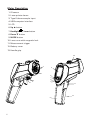
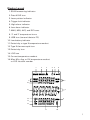
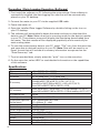
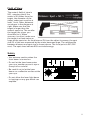
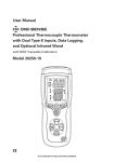
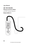
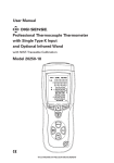
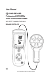
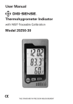
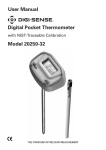
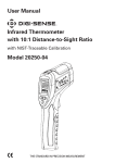
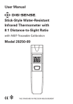
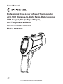
User Manual Professional Dual-Laser Infrared Thermometer with 50:1 Distance-to-Sight Ratio, Data Logging, USB Output, Single Type K Input, and Temperature Alarm with NIST-Traceable Calibration Model 20250-08 THE STANDARD IN PRECISION MEASUREMENT Introduction The Digi-Sense Professional Dual-Laser Infrared Thermometer (Model 20250-08) with 50 to 1 distance-to-sight ratio offers fast response and high accuracy. This heavy-duty meter is ideal for a wide range of applications including food preparation, safety and fire inspection, plastic molding, marine, HVAC, and fleet maintenance. Advanced features include internal data logging, USB interface for data transmission, temperature alarm, adjustable emissivity, temperature differential, data Hold, Max/Min/Avg readings, and auto power-off. The meter also supports contact measurement through a type K thermocouple input. The instrument is fully tested and calibrated to NIST-traceable standards. Careful use of this meter will provide years of reliable service. Unpacking Check individual parts against the list of items below. If anything is missing or damaged, please contact your instrument supplier immediately. 1. Meter 2. One type K flexible probe 3. USB cable 4. Software 5. Tripod 6. Carrying case 7. One 9 V battery 8. User manual 9. NIST-traceable calibration report with data 2 Key Features • 50:1 Distance-to-sight ratio • 1.5% basic accuracy • Dual laser sighting • Internal data logging up to 100 IR readings • USB interface for transmission of data to PC • Contact measurements via type K thermocouple input • Precise noncontact IR measurements • Rapid detection function • Adjustable emissivity from 0.10 to 1.0 • User-selectable ºC or ºF units • Automatic data Hold • MAX/MIN/AVG temperature displays • Temperature differential • High and low alarms (audible) • Automatic selection range and display resolution • Trigger lock • Backlight LCD • Automatic selection range and display resolution • Automatic power-off to conserve battery life 3 Meter Description 1. IR sensor 2. Laser pointer beam 3. Type K thermocouple input 4. USB computer interface 5. LCD 6. Up button 7. Backlight / Laser button 8. Down button 9. MODE button 10. Lens cover with magnetic lock 11. Measurement trigger 12. Battery cover 13. Handle grip 10 2 5 1 4 3 6 7 8 9 11 12 13 4 Display Layout 1. SCAN measuring indicator 2. Data HOLD icon 3. Laser pointer indicator 4. Trigger lock indicator 5. High alarm indicator 6. Low alarm indicator 7. MAX, MIN, AVG, and DIF icons 8. °C and °F temperature icons 9. USB icon (transmit data to PC) 10. Low-battery indicator 11. Emissivity or type K temperature readout 12. Type K thermocouple icon 13. Emissivity icon 14. LOG icon 15. Current temperature readout 16. Max, Min, Avg, or Dif temperature readout or LOG location number 1 2 3 4 5 6 7 7 16 8 15 14 LOG 9 13 12 11 10 5 How it Works Infrared thermometers measure the surface temperature of an object. The unit’s optics sense emitted, reflected, and transmitted energy, which is collected and focused onto a detector. The unit’s electronics translate the information into a temperature reading which is displayed on the unit. The laser is used for aiming purposes only. Field of View Make sure that the target is larger than the unit’s spot size. The smaller the target, the closer you should be to it. When accuracy is critical, make sure the target is at least twice as large as the spot size. Distance and Spot Size As the distance (D) from the object increases, the spot size (S) of the area measured by the unit becomes larger. Locating a Hot Spot To find a hot spot, aim the thermometer outside the area of interest, then scan across with an up-and-down motion until you locate the hot spot. Emissivity Emissivity is a term used to describe the energy-emitting characteristics of materials. Most (90% of typical applications) organic materials and painted or oxidized surfaces have an emissivity of 0.95 (preset in the unit). Inaccurate readings will result from measuring shiny or polished metal surfaces. To compensate, cover the surface to be measured with black tape or flat black paint. Allow time for the tape to reach the same temperature as the material underneath it. Measure the temperature of the tape or painted surface. (Refer to table on facing page.) Good Measuring Practices Holding the meter by its handle, point the IR sensor toward the object whose temperature is to be measured. The meter automatically compensates for temperature deviations from ambient temperature. Keep in mind that it will take up to 30 minutes for the IR sensor to stabilize if going from ambient temperatures to a much higher (or lower) temperature measurement. Reminders • The unit is not recommended for measuring shiny or polished metal surfaces (stainless steel, aluminum, etc.). See Emissivity above. • The unit cannot measure through transparent surfaces such as glass. It will measure the surface temperature of the glass instead. • Steam, dust, smoke, etc. can prevent accurate measurement by obstructing the unit’s optics. 6 Emissivity Values Substance Asphalt Concrete Cement Sand Earth Water Ice Snow Glass Ceramic Marble Plaster Mortar Brick Thermal emissivity 0.90 to 0.98 0.94 0.96 0.90 0.92 to 0.96 0.92 to 0.96 0.96 to 0.98 0.83 0.90 to 0.95 0.90 to 0.94 0.94 0.80 to 0.90 0.89 to 0.91 0.93 to 0.96 Substance Cloth (black) Human skin Lather Charcoal (powder) Lacquer Lacquer (matte) Rubber (black) Plastic Timber Paper Chromium oxides Copper oxides Iron oxides Textiles Thermal emissivity 0.98 0.98 0.75 to 0.80 0.96 0.80 to 0.95 0.97 0.94 0.85 to 0.95 0.90 0.70 to 0.94 0.81 0.78 0.78 to 0.82 0.90 Setup and Operation 1. Hold the meter by its handle grip and point it toward the surface to be measured. 2. P ull and hold the trigger to turn the meter on and begin testing. The display will light if the battery is good. Replace the battery if the display does not light. Meter automatically powers down after 10 seconds once the trigger is released. 3. While measuring, the SCAN icon will appear in the upper left-hand corner of the LCD. 4. Release the trigger and the HOLD icon will appear at the top of the LCD, indicating that the reading is being held. 5. While in the HOLD mode, press the MODE button to access and set the Max/Min/ Avg/Dif readings, emissivity (EMS) value, trigger lock (on/off), high alarm (on/off and set point), low alarm (on/off and set point), and temperature units (°C or °F). Each time you press the MODE button, you advance through each option. Refer to the flow chart on page 8 to see the sequence of functions in the mode cycle. a. Emissivity (EMS). When the Emissivity icon is flashing, use the Up and Down buttons to adjust the value from 0.10 to 1. Then press the MODE button again to enter setting. Note: If the type K thermocouple is connected, you cannot adjust emissivity. b. T rigger Lock. Use for continuous monitoring of temperatures. When the Lock icon is flashing, use the Up or Down button to turn “on”. Then press the MODE button again to enter setting. Once you press the measurement trigger, the Lock icon is shown, confirming the lock measurement mode. The meter will continuously display the temperature until the measurement trigger is pressed again. 7 Setup and Operation (continued) c. High Alarm. When the High alarm icon is flashing, use the Up or Down button to turn “on”. Then press the MODE button again to enter setting. The High alarm icon will still be flashing, allowing you to set the alarm trigger temperature set point using the Up and Down buttons. Press MODE button again to enter setting. d. Low Alarm. When the Low alarm icon is flashing, use the Up or Down button to turn “on”. Then press the MODE button again to enter setting. The Low alarm icon will still be flashing, allowing you to set the alarm trigger temperature set point using the Up and Down buttons. Press MODE button again to enter setting. 6. Max, Min, Avg, Dif, Log Readings. While measuring, pressing the MODE button will allow you to toggle between maximum, minimum, average, differential, and logged readings. 7. Laser Pointer and Backlight Functions. Press the Backlight/Laser button to turn the laser and backlight functions on and off at any stage. 8. USB Function. Meter will transmit the IR and T/C measurement data to a PC via USB interface. While in measurement mode, press and hold the Backlight/Laser button until the USB icon appears in the lower corner of the LCD, indicating the function is turned on. Press and hold the Backlight/Laser button again to turn off the USB function; the USB icon will then disappear from the LCD. Note: Install software according to steps on page 10. Setup MODE Flow Chart 8 Recording/Data Logging Operation (Meter) This meter is capable of storing up to 100 IR temperature readings into internal memory. Storing Data 1. W hile holding the trigger, press the MODE button until the LOG icon appears in the lower left corner of the screen. A LOG location number will be shown in the top display and “_ _ _ _” will appear in the bottom display if no temperature has been saved to that location (Fig. 1). LOG 2. P ress the Backlight/Laser button to log a temperature reading into an empty location (Fig. 2); a short beep will sound. If that location has already been used, you can use the Up and Down buttons to move to an empty location. Fig. 1 Recalling Stored Data 1. Press the MODE button until the LOG icon appears in the lower left corner of the display. A LOG location number will be shown in the top display and the stored temperature for that location will be shown in the bottom display (Fig. 2). 2. To move to another LOG location, use the Up and Down buttons. LOG Clearing Stored Data Fig. 2 1. W hile in LOG mode, hold the trigger, and use the Up and Down buttons until you reach LOG location “000” (Fig. 3). This can only be done when the trigger is being pulled, otherwise LOG location “000” cannot be accessed. 2. When LOG location “000” is shown in the top display, press the Backlight/Laser button. Three short beeps will sound and the LOG location will automatically change to “001”, signifying that all data locations have been cleared. 3. Note: Only use the clear function if you want to clear all the stored data. LOG Fig. 3 9 Recording / Data Logging Operation (Software) 1. First install the software on PC following the setup wizard. Once software is successfully installed, the data logging icon shortcut will be automatically placed on your PC desktop. 2. Connect the meter to your PC via the supplied USB cable. 3. Power the meter on. 4. Open the installed Data Logger Software by double-clicking on the icon on your PC desktop. 5. The software will automatically detect the meter and start to download the data to your PC. Note: Meter must be in scanning mode for the data to transfer to your PC. The software screen will display the data being downloaded from the meter. The data results will be displayed graphically and numerically for each reading taken. 6. To save the measurement data to your PC, select “File” icon from the menu bar and save data to desired location on your PC. Note: Data will be saved in an Excel® format that will include all summary information as captured on the “Data Summary” tab. 7. To print recorded data, simply select the “print” icon on the menu bar. 8. On the menu bar, select HELP to read detailed information on the capabilities of this software. Specifications IR temperature range T/C temperature range Resolution IR accuracy 10 –58 to 3362°F (–50 to 1850°C) –58 to 2498°F (–50 to 1370°C) 0.1°F/C below 1000°, 1°F/C above 1000° From –58 to 68°F (–50 to 20°C): ±5.4°F (3°C) From 68 to 932°F (20 to 500°C): ±1.0% ± 1.8°F (1°C) From 932 to 1832°F (500 to 1000°C): ±1.5% ± 3.6°F (2.0°C) From 1832 to 3362°F (1000 to 1850°C): ±2.0% T/C accuracy From –58 to 1832°F (–50 to 1000°C): ±1.5% of reading ± 5°F (±3°C) From 1832 to 2498°F (1000 to 1370°C): ±1.5% of reading ± 3.6°F (±2°C) IR response time Emissivity Distance-to-sight ratio (field of view) Laser Spectral range Out-of-range indication Operating temperature Storage temperature Weight Dimensions Power 150 ms Adjustable from 0.10 to 1.0 D/S = approximately 50:1 ratio (D = distance, S = spot) Dual Class 2 (II) lasers 8 to 14 µm LCD will show “----” 32 to 122°F (0 to 50°C) 14 to 140°F (–10 to 60°C) 17.4 oz (494 g) 71⁄2 " x 6" x 21⁄4 " (18.9 x 15.2 x 5.7 cm) One 9 V battery Field of View The meter’s field of view is 50:1, meaning that if the meter is 50 inches from the target, the diameter of the object under test must be at least 1 inch. Other distances are shown in the diagram at right. Make sure that the target is larger than the meter’s spot size. The smaller the target, the closer you should be to it. When accuracy is critical, make sure the target is at least twice as large as the spot size. As the distance (D) from the object increases, the spot size (S) of the area measured by the meter becomes large. The relationship between distance and spot size is shown above. The focal point is 36" (914 mm). The spot sizes indicate 90% encircled energy. Safety • Use extreme caution when the laser beam is turned on. • Do not let the laser beam enter your eye, another person’s eye or the eye of an animal. • Be careful not to let the laser beam on a reflective surface strike your eye. • Do not allow the laser light beam to impinge on any gas which can explode. 11 Maintenance, Recalibration, and Repair Cleaning and Storage • The meter should be cleaned with a damp cloth and mild detergent when necessary. Do not use solvents or abrasives. • Store the meter in an area with moderate temperature and humidity (refer to the operating and storage temperatures on page 10). Battery Replacement If the battery power is insufficient, the Low-battery icon will appear on the LCD. Open the battery cover and replace the 9 V battery. Securely close the cover. 9V battery Open battery cover It is recommended that Digi-Sense products are calibrated annually to ensure proper function and accurate measurements; however, your quality system or regulatory body may require more frequent calibrations. To schedule your recalibration, please contact InnoCal, an ISO 17025 calibration laboratory accredited by A2LA. Phone: 1-866-INNOCAL (1-866-466-6225) Fax: 1-847-327-2993 E-mail: [email protected] Web: InnoCalSolutions.com For Product and Ordering Information, Contact: Toll-Free: 1-800-323-4340 Phone: 1-847-549-7600 Fax: 1-847-247-2929 ColeParmer.com/Digi-Sense 1065DGMAN_20250-08 Rev.1 Toll-Free: 1-800-358-5525 Phone: 1-847-327-2000 Fax: 1-847-327-2700 Davis.com/Digi-Sense Manual Part No. 00100-46