1
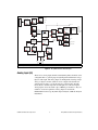
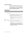
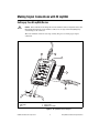
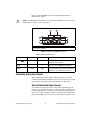
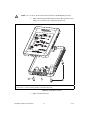
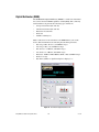
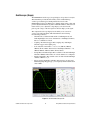
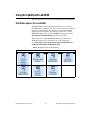
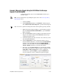
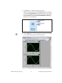
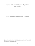
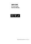
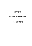
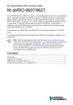
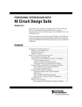
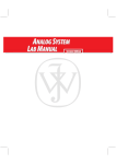
USER GUIDE AND SPECIFICATIONS NI myDAQ Français Deutsch ni.com/manuals NI myDA Q Figure 1. NI myDAQ NI myDAQ is a low-cost portable data acquisition (DAQ) device that uses NI LabVIEW-based software instruments, allowing students to measure and analyze real-world signals. NI myDAQ is ideal for exploring electronics and taking sensor measurements. Combined with NI LabVIEW on the PC, students can analyze and process acquired signals and control simple processes anytime, anywhere. Contents Conventions ............................................................................................ 3 Safety Information .................................................................................. 3 Electromagnetic Compatibility Guidelines............................................. 3 NI myDAQ Hardware Overview.............................................................4 Analog Input (AI) .............................................................................5 Analog Output (AO).........................................................................6 Digital Input/Output (DIO)...............................................................6 Power Supplies .................................................................................6 Digital Multimeter (DMM) ..............................................................7 NI myDAQ Software Overview ..............................................................7 NI ELVISmx Driver Software..........................................................7 NI LabVIEW and NI ELVISmx Express VIs ..................................7 NI myDAQ and NI Multisim ...........................................................8 Getting Started .........................................................................................8 Making Signal Connections with NI myDAQ ........................................9 Setting up Your NI myDAQ Device ................................................9 Connecting Signals...........................................................................10 Connecting Analog Input Signals.....................................................11 NI myDAQ DMM Fuse Replacement..............................................14 Digital I/O (DIO) and Counters/Timers ..................................................17 Using NI myDAQ with Soft Front Panel (SFP) Instruments ..................18 NI ELVISmx Instrument Launcher ..................................................19 Digital Multimeter (DMM) ..............................................................20 Oscilloscope (Scope) ........................................................................21 Function Generator (FGEN).............................................................22 Bode Analyzer ..................................................................................23 Dynamic Signal Analyzer (DSA).....................................................24 Arbitrary Waveform Generator (ARB) ............................................25 Digital Reader...................................................................................26 Digital Writer....................................................................................27 Example: Measuring a Signal Using the NI ELVISmx Oscilloscope SFP with NI myDAQ...............................................28 Using NI myDAQ with LabVIEW ..........................................................29 NI ELVISmx Express VIs in LabVIEW ..........................................29 Example: Measuring Signals Using the NI ELVISmx Oscilloscope Express VI with NI myDAQ....................................30 Using NI-DAQmx with NI myDAQ ................................................32 Example: Measuring Audio Pass-Through in LabVIEW with NI myDAQ ....................................................................................32 Specifications...........................................................................................36 Texas Instruments Components in NI myDAQ ......................................48 Resource Conflicts...................................................................................50 Additional Resources...............................................................................52 Related Documentation ....................................................................52 Other Resources................................................................................53 Common Terms and Acronyms........................................................53 Warranty ...........................................................................................54 Where to Go for Support ..................................................................54 NI myDAQ User Guide and Specifications 2 ni.com Conventions The following conventions are used in this manual: This icon denotes a tip, which alerts you to advisory information. This icon denotes a note, which alerts you to important information. This icon denotes a caution, which advises you of precautions to take to avoid injury, data loss, or a system crash. CAUTION—The inputs/outputs of this product can be damaged if subjected to Electrostatic Discharge (ESD). To prevent damage, industry-standard ESD prevention measures must be employed during installation, maintenance, and operation. Safety Information Do not operate the hardware in a manner not specified in this document and in the user documentation. Misuse of the hardware can result in a hazard. You can compromise the safety protection if the hardware is damaged in any way. If the hardware is damaged, return it to National Instruments for repair. Clean the hardware with a soft, nonmetallic brush. Make sure that the hardware is completely dry and free from contaminants before returning it to service. Electromagnetic Compatibility Guidelines This product was tested and complies with the regulatory requirements and limits for electromagnetic compatibility (EMC) as stated in the product specifications. These requirements and limits are designed to provide reasonable protection against harmful interference when the product is operated in its intended operational electromagnetic environment. This product is intended for use in residential, commercial, and industrial locations. There is no guarantee that harmful interference will not occur in a particular installation or when the product is connected to a test object. To minimize the potential for the product to cause interference to radio and television reception or to experience unacceptable performance degradation, install and use this product in strict accordance with the instructions in the product documentation. © National Instruments Corporation 3 NI myDAQ User Guide and Specifications Furthermore, any changes or modifications to the product not expressly approved by National Instruments could void your authority to operate it under your local regulatory rules. NI myDAQ Hardware Overview NI myDAQ provides analog input (AI), analog output (AO), digital input and output (DIO), audio, power supplies, and digital multimeter (DMM) functions in a compact USB device. Tip The Common Terms and Acronyms section has a list of acronyms and terms that you will see in this manual, and in many engineering and measurement documents and websites. Integrated circuits supplied by Texas Instruments form the power and analog I/O subsystems of NI myDAQ. Figure 2 depicts the arrangement and function of the NI myDAQ subsystems. Refer to Table 5 for more information on all of the Texas Instruments components used in NI myDAQ. NI myDAQ User Guide and Specifications 4 ni.com +15 V USB Connector Regulator VBUS Current Limiter Protection Circuit (TPS61170) –15 V (TPS2553) (CSD25302Q2) +5 V 8 DIO x Regulator (TPS62003) Instrumentation Amplifier Gain ADC +1.2 V (TLE2082) (OPA1642) (ADS8319) Channel Multiplexer Regulator (TPS62007) +3.3 V USB-STC3 DAC OP AMP (DAC8551) +3.3 V AI 0+ AI 0 – AI 1+ AI 1 – Line In R Line In L (OPA1642) AO 0 Switch (TS12A44514) OP AMP (OPA1642) Digital Isolator DC/DC Isolation Transformer AO 1 Isolation Barrier (ISO7241) Audio AMP (TPA6110A2) Line Out R Line Out L LDO Regulator LDO Regulator (TPS71501) (TPS76433) Shift Register (SN74AHC595) Isolated +3.3 V DMM Isolated +5 V Switch (TS5A3159) HI COM (V Ω ) HI (A) Note: NI myDAQ components may be changed or substituted without notice. Figure 2. NI myDAQ Hardware Block Diagram Analog Input (AI) There are two analog input channels on NI myDAQ. These channels can be configured either as general-purpose high-impedance differential voltage input or audio input. The analog inputs are multiplexed, meaning a single analog-to-digital converter (ADC) is used to sample both channels. In general-purpose mode, you can measure up to ±10 V signals. In audio mode, the two channels represent left and right stereo line level inputs. Analog inputs can be measured at up to 200 kS/s per channel, so they are useful for waveform acquisition. Analog inputs are used in the NI ELVISmx Oscilloscope, Dynamic Signal Analyzer, and Bode Analyzer instruments. © National Instruments Corporation 5 NI myDAQ User Guide and Specifications Analog Output (AO) There are two analog output channels on NI myDAQ. These channels can be configured as either general-purpose voltage output or audio output. Both channels have a dedicated digital-to-analog converter (DAC), so they can update simultaneously. In general-purpose mode, you can generate up to ±10 V signals. In audio mode, the two channels represent left and right stereo outputs. Caution If using earphones to listen to the audio output of the NI myDAQ, ensure that the volume is set to a safe level. Listening to audio signals at a high volume may result in permanent hearing loss. Analog outputs can be updated at up to 200 kS/s per channel, making them useful for waveform generation. Analog outputs are used in the NI ELVISmx Function Generator, Arbitrary Waveform Generator, and Bode Analyzer instruments. Digital Input/Output (DIO) There are eight DIO lines on NI myDAQ. Each line is a Programmable Function Interface (PFI), meaning that it can be configured as a general-purpose software-timed digital input or output, or it can act as a special function input or output for a digital counter. Refer to Digital I/O (DIO) and Counters/Timers section for more information about the counter on NI myDAQ. Note The digital I/O lines are 3.3 V LVTTL and are tolerant to 5 V inputs. The digital output is not compatible with 5 V CMOS logic levels. Power Supplies There are three power supplies available for use on NI myDAQ. +15 V and –15 V can be used to power analog components such as operational amplifiers and linear regulators. +5 V can be used to power digital components such as logic devices. The total power available for the power supplies, analog outputs, and digital outputs is limited to 500 mW (typical)/100 mW (minimum). To calculate the total power consumption of the power supplies, multiply the output voltage by the load current for each voltage rail and sum them together. For digital output power consumption, multiply 3.3 V by the load current. For analog output power consumption, multiply 15 V by the load current. Using audio output subtracts 100 mW from the total power budget. NI myDAQ User Guide and Specifications 6 ni.com For example, if you use 50 mA on +5 V, 2 mA on +15 V, 1 mA on –15 V, use four DIO lines to drive LEDs at 3 mA each, and have a 1 mA load on each AO channel, the total output power consumption is: 5 V 50 mA = 250 mW |+15 V| 2 mA = 30 mW |–15 V| 1 mA = 15 mW 3.3 V 3 mA 4 = 39.6 mW 15 V 1 mA 2 = 30 mW Total output power consumption = 250 mW + 30 mW + 15 mW + 39.6 mW + 30 mW = 364.6 mW Digital Multimeter (DMM) The NI myDAQ DMM provides the functions for measuring voltage (DC and AC), current (DC and AC), resistance, and diode voltage drop. DMM measurements are software-timed, so update rates are affected by the load on the computer and USB activity. NI myDAQ Software Overview NI ELVISmx Driver Software NI ELVISmx is the driver software that supports NI myDAQ. NI ELVISmx uses LabVIEW-based software instruments to control the NI myDAQ device, providing the functionality of a suite of common laboratory instruments. Refer to the Using NI myDAQ with Soft Front Panel (SFP) Instruments section for information on the NI ELVISmx suite of measurement instruments. NI ELVISmx is located on your driver software installation media included in the NI myDAQ kit, or can be found by searching for ELVISmx on the Drivers and Updates page at ni.com/drivers. To determine the version of NI ELVISmx software support required for your version of LabVIEW, go to ni.com/info and enter the Info Code ELVISmxsoftware. NI LabVIEW and NI ELVISmx Express VIs Also installed with NI ELVISmx are the LabVIEW Express VIs, which use NI ELVISmx software instruments to program NI myDAQ with more enhanced functionality. For more information on the NI ELVISmx Express VIs, refer to the Using NI myDAQ with LabVIEW section. Note NI ELVISmx supports LabVIEW (32 bit). To use NI ELVISmx with LabVIEW on a 64-bit operating system, you must have LabVIEW (32 bit) installed. © National Instruments Corporation 7 NI myDAQ User Guide and Specifications NI myDAQ and NI Multisim You can use NI ELVISmx instruments in NI Multisim to simulate a circuit, measure the real signals with NI myDAQ, and compare simulated and acquired data. To see step-by-step instructions for using NI ELVISmx instruments in NI Multisim, refer to Using NI ELVISmx in NI Multisim help file, installed with NI ELVISmx. To access this help file, go to Start» All Programs»National Instruments»NI ELVISmx for NI ELVIS & NI myDAQ»Using NI ELVISmx in NI Multisim. Getting Started Caution For EMC compliance, the USB cable must be less than 2.0 m (6.6 ft) in length. Also, wires attached to the MIO screw terminal connector must be limited to 30.0 cm (11.8 in.) in length. Getting started with NI myDAQ is a simple process, but it is important to ensure that you install the right components in the correct order. To get started with your NI myDAQ, complete the following steps: 1. Install the NI myDAQ Software Suite from the DVD shipped with your device. The NI myDAQ Software Suite installs application software (NI LabVIEW, NI Multisim) first, and then installs the NI ELVISmx driver software. Note If you are not installing software from the NI myDAQ Software Suite media, make sure to install all application software before installing the driver software. 2. Connect the cable from the computer Hi-Speed USB port to the USB port on the device. The computer will recognize the NI myDAQ and the NI ELVISmx Instrument Launcher appears. You can also manually open NI ELVISmx Instrument Launcher by selecting Start»All Programs» National Instruments»NI ELVISmx for NI ELVIS & NI myDAQ» NI ELVISmx Instrument Launcher. NI myDAQ User Guide and Specifications 8 ni.com Making Signal Connections with NI myDAQ Setting up Your NI myDAQ Device Caution Insert and remove the 20-position screw terminal connector aligned evenly to the NI myDAQ. Inserting the screw terminal connector at an angle to the NI myDAQ may cause damage to the connector. The screw terminal connector must snap securely into place to ensure proper signal connection. 2 1 3 NI myDA Q 4 5 6 1 2 3 NI myDAQ USB Cable LED 4 5 6 20-Position Screw Terminal Connector Audio Cable DMM Banana Cable Figure 3. NI myDAQ Connection Diagram © National Instruments Corporation 9 NI myDAQ User Guide and Specifications Connecting Signals Figure 4 shows the available audio, AI, AO, DIO, GND, and power signals accessed through the 3.5 mm audio jacks and screw terminal connections. Refer to Table 1 for descriptions of these signals. Signal wires must be securely affixed and screwed down in the screw terminal connector to ensure proper connection. Caution AUDIO IN AUDIO OUT Figure 4. NI myDAQ 20-Position Screw Terminal I/O Connector Table 1. Screw Terminal Signal Descriptions Signal Name Reference Direction Description AUDIO IN — Input Audio Input—Left and right audio inputs on a stereo connector AUDIO OUT — Output Audio Output—Left and right audio outputs on a stereo connector AGND Output +15 V/–15 V power supplies — — AO 0/AO 1 AGND Output AI 0+/AI 0–; AI 1+/AI 1– AGND Input DIO <0..7> DGND Input or Output — — DGND Output +15V/–15V AGND DGND 5V NI myDAQ User Guide and Specifications Analog Ground—Reference terminal for AI, AO, +15 V, and –15 V Analog Output Channels 0 and 1 Analog Input Channels 0 and 1 Digital I/O Signals—General-purpose digital lines or counter signals Digital Ground—Reference for the DIO lines and the +5 V supply 5 V power supply 10 ni.com Figure 5 shows the DMM connections on the NI myDAQ. Table 2 describes these signals. 60 VDC/20 Vrms maximum. Do not plug digital multimeter probes into circuits with Hazardous Voltages, such as wall outlets. Caution 1 1 2 2 Connectors for Voltage/Resistance/Diode/Continuity Connectors for Current Figure 5. Connections for DMM Measurements Table 2. DMM Signal Descriptions Signal Name Reference Direction COM Input COM — — HI (A) COM Input HI (V ) Description Positive terminal for voltage, resistance, and diode measurements Reference for all DMM measurements Positive terminal for current measurements (Fused: F 1.25 A 250 V Fast-Acting) Connecting Analog Input Signals When configuring the input channels and making signal connections, you must first determine whether the signal sources are floating or ground referenced. The following sections describe these two signal types. Ground-Referenced Signal Sources A ground-referenced signal source is connected to the building system ground, so it is already connected to a common ground point with respect to the NI myDAQ device, assuming that the computer is plugged into the same power system. Instruments or devices with nonisolated outputs that plug into the building power system are ground-referenced signal sources. © National Instruments Corporation 11 NI myDAQ User Guide and Specifications Note Most laptop computers have isolated power supplies, and are consequently not connected to the building ground system. In these cases, treat the analog input signal as floating with respect to NI myDAQ. The difference in ground potential between two instruments connected to the same building power system is typically between 1 and 100 mV. This difference can be much higher if power distribution circuits are improperly connected. If a grounded signal source is improperly measured, this difference might appear as a measurement error. Connect the differential analog inputs across the signal source and do not connect the NI myDAQ AGND pin to the grounded source. Signal Source + – AI+ + AI– – AGND Figure 6. Ground-Referenced Differential Connection Floating Signal Sources A floating signal source is not connected to the same ground reference as NI myDAQ, but instead has an isolated reference point. Some examples of floating signal sources are battery-powered devices, outputs of transformers, thermocouples, optical isolator outputs, and isolation amplifiers. An instrument or device that has an isolated output is a floating signal source. You must connect the ground reference of a floating signal to an NI myDAQ AGND pin through a bias resistor or jumper wire to establish a local or onboard reference for the signal. Otherwise, the measured input signal varies as the source floats out of the common-mode input range. The easiest way to reference the source to AGND is to connect the positive side of the signal to AI+ and connect the negative side of the signal to AGND as well as to AI– without using resistors. This connection works well for DC-coupled sources with low source impedance (less than 100 ). NI myDAQ User Guide and Specifications 12 ni.com Signal Source + – Rsource <100 Ω AI+ + AI– – AGND Figure 7. Differential Connections for Floating Signal Sources without Resistors For larger source impedances, however, this connection leaves the differential signal path significantly off balance. Noise that couples electrostatically onto the positive line does not couple onto the negative line because it is connected to ground. This noise appears as a differential-mode signal instead of a common-mode signal, and thus appears in your data. In this case, instead of directly connecting the negative line to AGND, connect the negative line to AGND through a resistor that is about 100 times the equivalent source impedance. The resistor puts the signal path nearly in balance, so that about the same amount of noise couples onto both connections, yielding better rejection of electrostatically coupled noise. This configuration does not load down the source. Signal Source + – Rsource >100 Ω AI+ + AI– – AGND Figure 8. Differential Connections for Floating Signal Sources with a Single Resistor You can fully balance the signal path by connecting another resistor of the same value between the positive input and AGND, as shown in Figure 9. This fully balanced configuration offers slightly better noise rejection, but has the disadvantage of loading the source down with the series combination (sum) of the two resistors. If, for example, the source impedance is 2 k and each of the two resistors is 100 k, the resistors load down the source with 200 k and produce a –1% gain error. © National Instruments Corporation 13 NI myDAQ User Guide and Specifications Signal Source + – Rsource >100 Ω AI+ + AI– – AGND Figure 9. Differential Connections for Floating Signal Sources with Two Resistors Both positive and negative analog input lines require a DC path to ground in order for the instrumentation amplifier to work. If the source is AC coupled (capacitively coupled), a resistor is needed between the positive input and AGND. If the source has low impedance, choose a resistor that is large enough not to significantly load the source but small enough not to produce significant input offset voltage as a result of input bias current (typically 100 k to 1 M). In this case, connect the negative input directly to AGND. If the source has high output impedance, balance the signal path as previously described using the same value resistor on both the positive and negative inputs. NI myDAQ DMM Fuse Replacement NI myDAQ has a fuse to protect the device from overcurrent through HI (A) current measurement input on the DMM. If the DMM soft front panel (SFP) always reads 0 A current, the cause may be a blown fuse. Testing Your Fuse To test for a blown fuse, complete the following steps. 1. Using a banana cable, connect the HI (V) and HI (A) DMM terminals. 2. Launch the NI ELVISmx Digital Multimeter (DMM) Soft Front Panel instrument from the NI ELVISmx Instrument Launcher, located at Start»All Programs»National Instruments»NI ELVISmx for NI ELVIS & NI myDAQ»NI ELVISmx Instrument Launcher. 3. Select the Resistance mode. 4. Set the Range to 200 . 5. Click Run. 6. If the fuse is blown, the display will show +Over, indicating a disconnected circuit path. Replace the fuse and complete the procedure again. NI myDAQ User Guide and Specifications 14 ni.com Replacing the Fuse Replace broken fuses with a 1.25 A Fast-Acting sand-filled 5 20 mm fuse (Littelfuse part number 02161.25 at www.littelfuse.com). To replace a broken fuse, complete the following steps. 1. Power down the device by properly disconnecting it from the PC and removing the USB cable. 2. Remove the screw terminal connector and all other signal cables from the device. 3. Loosen the four Phillips screws that attach the bottom of the enclosure to the device, and remove the top lid of the enclosure. © National Instruments Corporation 15 NI myDAQ User Guide and Specifications Caution Do not remove the board from the bottom half of the NI myDAQ enclosure. 4. Replace the broken fuse while referring to Figure 10 for the fuse location, taking care to not damage any components on the board. NI myDAQ 1 1 2 2 1 Enclosure Screws Internal Fuse—1.25 A Fast-Acting (Littelfuse Part Number 02161.25) Figure 10. NI myDAQ Fuse Location 5. Replace the lid and screws. NI myDAQ User Guide and Specifications 16 ni.com Digital I/O (DIO) and Counters/Timers There are eight, software-timed DIO lines on the NI myDAQ that can be individually configured for input or output. Additionally, lines DIO <0..4> can be configured for counter/timer functionality. The input—accessed through DIO 0, DIO 1, and DIO 2 signals configured as a counter—is used for counter, timer, pulse width measuring, and quadrature encoding applications. When using the counter/timer, the Source is accessed through DIO 0, the Gate through DIO 1, the Auxiliary Input through DIO 2, the Output through DIO 3, and the Frequency Output through DIO 4. When using the counter/timer as a quadrature encoder, A, Z, and B correspond to DIO 0, DIO 1, and DIO 2, respectively. In some instances, the software may refer to the output lines as PFI as opposed to DIO. Refer to Table 3 for a list of the corresponding counter/timer signals assignments through the DIO terminals. Table 3. NI myDAQ Counter/Timer Signal Assignments NI myDAQ Signal Programmable Function Interface (PFI) DIO 0 PFI 0 CTR 0 SOURCE A DIO 1 PFI 1 CTR 0 GATE Z DIO 2 PFI 2 CTR 0 AUX B DIO 3* PFI 3 CTR 0 OUT — DIO 4 PFI 4 FREQ OUT — * Counter/Timer Signal Quadrature Encoder Signal Pulse-width modulation (PWM) pulse train measurements are generated through DIO 3 For more information about event timing requirements, refer to the Specifications section. For more detailed information on using counter/timers with NI myDAQ, refer to the KnowledgeBase document How Do I Use the NI myDAQ Counter?. To access this document, go to ni.com/info and enter the Info Code mydaqcounter. © National Instruments Corporation 17 NI myDAQ User Guide and Specifications Using NI myDAQ with Soft Front Panel (SFP) Instruments Note Before opening a SFP, make sure that the NI myDAQ device is connected to the system and is ready to use. After the NI myDAQ is connected to the system, the blue LED lights, indicating the device is ready for use, and the NI ELVISmx Instrument Launcher launches automatically. NI ELVISmx provides soft front panel (SFP) instruments, created in LabVIEW, and the source code for the instruments. You cannot directly modify the executable files, but you can modify or enhance the functionality of these instruments by modifying the LabVIEW code, which installs in the following location: • Windows XP/2000: C:\Documents and Settings\All Users\Shared Documents\ National Instruments\NI ELVISmx Source Code • Windows 7/Vista: C:\Users\Public\Documents\National Instruments\ NI ELVISmx Source Code Note For a detailed explanation of the SFP instruments, instructions for taking a measurement with each instrument, and information on the other NI ELVISmx Instrument Launcher features, refer to the NI ELVISmx Help. To access this help file, go to Start» All Programs»National Instruments»NI ELVISmx for NI ELVIS & NI myDAQ» NI ELVISmx Help. NI myDAQ User Guide and Specifications 18 ni.com NI ELVISmx Instrument Launcher The NI ELVISmx Instrument Launcher provides access to the NI ELVISmx SFP instruments, additional featured instruments, documentation and online resource links, and personal file access. When you install the NI myDAQ device, the NI ELVISmx Instrument Launcher automatically opens. To manually open the Instrument Launcher, navigate to Start»All Programs»National Instruments»NI ELVISmx for NI ELVIS & NI myDAQ»NI ELVISmx Instrument Launcher. This opens the suite of LabVIEW SFP instruments. Figure 11. NI ELVISmx Instrument Launcher To launch an instrument, click the button corresponding to the desired instrument. Select the NI myDAQ device from the Device control. Some instruments perform similar operations using the same resources of the NI myDAQ hardware and therefore cannot run at the same time. If you launch two instruments with overlapping functionality that cannot run at the same time, the NI ELVISmx software generates an error dialog describing the conflict. The instrument with the error is disabled and will not function until the conflict is resolved. For information about possible resource conflicts, refer to the Resource Conflicts section. © National Instruments Corporation 19 NI myDAQ User Guide and Specifications Digital Multimeter (DMM) The NI ELVISmx Digital Multimeter (DMM) is a stand-alone instrument that controls the basic DMM capabilities of NI myDAQ. This commonly used instrument can perform the following types of functions: • Voltage measurement (DC and AC) • Current measurement (DC and AC) • Resistance measurement • Diode test • Audible continuity test Make connections for measurements to the DMM banana jacks on the device. This instrument has the following measurement parameters: • DC voltage: 60 V, 20 V, 2 V, and 200 mV ranges • AC voltage: 20 V, 2 V, and 200 mV ranges • DC current: 1 A, 200 mA, and 20 mA ranges • AC current: 1 A, 200 mA, and 20 mA ranges • Resistance: 20 M, 2 M, 200 k, 20 k, 2 k, and 200 ranges • Diode: 2 V range • Resolution (number of significant digits for display): 3.5 Figure 12. NI ELVISmx Digital Multimeter SFP NI myDAQ User Guide and Specifications 20 ni.com Oscilloscope (Scope) The NI ELVISmx Oscilloscope (Scope) displays voltage data for analysis. This instrument provides the functionality of the standard desktop oscilloscope found in typical undergraduate laboratories. The NI ELVISmx Oscilloscope SFP has two channels and provides scaling and position adjustment knobs along with a modifiable timebase. The autoscale feature allows you to adjust the voltage display scale based on the peak-to-peak voltage of the AC signal for the best display of the signal. The computer-based scope display has the ability to use cursors for accurate screen measurements. This instrument has the following measurement parameters: • Channel Source: Channels AI 0 and AI 1; AudioInput Left, and AudioInput Right. You can use AI channels or AudioInput channels, but not a combination of both. • Coupling: AI Channels support DC Coupling only. AudioInput Channels support AC Coupling only. • Scale Volts/Div: AI channels—5 V, 2 V, 1 V, 500 mV, 200 mV, 100 mV, 50 mV, 20 mV, 10 mV and for AudioInput Channels—1 V, 500 mV, 200 mV, 100 mV, 50 mV, 20 mV, 10 mV. • Sample Rate: The Max Sample Rate available for AI and AudioInput Channels: 200 kS/s when either one or both channels are configured. • Timebase Time/Div: The available values for both AI and AudioInput channels: 200 ms to 5 s. • Trigger settings: Immediate and Edge Trigger Types are supported. When using Edge Trigger Type, you can specify a Horizontal Position of 0%–100%. Figure 13. NI ELVISmx Oscilloscope SFP © National Instruments Corporation 21 NI myDAQ User Guide and Specifications Function Generator (FGEN) The NI ELVISmx Function Generator (FGEN) generates standard waveforms with options for the type of output waveform (sine, square, or triangle), amplitude selection, and frequency settings. In addition, the instrument offers DC offset setting, frequency sweep capabilities, and amplitude and frequency modulation. The FGEN uses AO 0 or AO 1 on the screw terminal connector. This instrument has the following measurement parameters: • Output channel: AO 0 or AO 1 • Frequency range: 0.2 Hz to 20 kHz Figure 14. NI ELVISmx Function Generator SFP NI myDAQ User Guide and Specifications 22 ni.com Bode Analyzer The NI ELVISmx Bode Analyzer produces a Bode plot for analysis. By combining the frequency sweep feature of the function generator and the analog input capability of the device, a full-function Bode Analyzer is available with NI ELVISmx. You can set the frequency range of the instrument and choose between linear and logarithmic display scales. You can also invert the measured values of the input signal during Bode analysis by inverting the Op-Amp signal polarity. Refer to the NI ELVISmx Help for required hardware connections. To access this help file, go to Start» All Programs»National Instruments»NI ELVISmx for NI ELVIS & NI myDAQ»NI ELVISmx Help. This instrument has the following measurement parameters: • Stimulus measurement channel: AI 0 • Response measurement channel: AI 1 • Stimulus signal source: AO 0 • Frequency range: 1 Hz to 20 kHz Figure 15. NI ELVISmx Bode Analyzer SFP © National Instruments Corporation 23 NI myDAQ User Guide and Specifications Dynamic Signal Analyzer (DSA) The NI ELVISmx Dynamic Signal Analyzer (DSA) performs a frequency domain transform of the AI or Audio Input waveform measurement. It can either continuously make measurements or make a single scan. You can also apply various window and filtering options to the signal. This instrument has the following measurement parameters: • Source Channel: AI 0 and AI 1; AudioInput Left and AudioInput Right • Voltage Range: – For AI channels: ±10 V, ±2 V – For AudioInput channels: ±2 V Figure 16. NI ELVISmx Dynamic Signal Analyzer SFP NI myDAQ User Guide and Specifications 24 ni.com Arbitrary Waveform Generator (ARB) The NI ELVISmx Arbitrary Waveform Generator (ARB) generates a signal, displayed as an electrical waveform. This advanced-level SFP instrument uses the AO capabilities of the device. You can create a variety of signal types using the Waveform Editor software, which is included with the NI ELVISmx software. You can load waveforms created with the NI Waveform Editor into the ARB SFP to generate stored waveforms. Refer to the NI ELVISmx Help for more information about the Waveform Editor. To access this help file, go to Start»All Programs»National Instruments»NI ELVISmx for NI ELVIS & NI myDAQ»NI ELVISmx Help. Since the device has two AO and two AudioOutput channels, two waveforms may be simultaneously generated. You can choose to run continuously or run once. This instrument has the following measurement parameters: • Output Channels: AO 0 and AO 1; AudioOutput Left and AudioOutput Right. You can use AO channels or AudioOutput channels, but not a combination of both. • Trigger Source: Immediate only. This control will always be disabled. Figure 17. NI ELVISmx Arbitrary Waveform Generator SFP © National Instruments Corporation 25 NI myDAQ User Guide and Specifications Digital Reader The NI ELVISmx Digital Reader reads digital data from the NI myDAQ digital lines. NI ELVISmx Digital Reader groups the I/O lines into ports through which data can be read. You can read one port at a time, either continuously or as a single reading. The lines are grouped into two ports of four pins (0–3 and 4–7) or one port of eight pins (0–7). Figure 18. NI ELVISmx Digital Reader SFP NI myDAQ User Guide and Specifications 26 ni.com Digital Writer The NI ELVISmx Digital Writer updates the NI myDAQ digital lines with user-specified digital patterns. NI ELVISmx Digital Writer groups the I/O lines into ports through which data can be written. You can write a 4-bit pattern (0–3 or 4–7) or an 8-bit pattern (0–7). You can also manually create a pattern or select predefined patterns, such as ramp, toggle, or walking 1s. This instrument can control a port of four or eight consecutive lines and either continually output a pattern or just perform a single write. The output of the NI ELVISmx Digital Writer SFP stays latched until either another pattern is generated, the lines it is using are configured for read, or the power is cycled on the NI myDAQ. Figure 19. NI ELVISmx Digital Writer SFP © National Instruments Corporation 27 NI myDAQ User Guide and Specifications Example: Measuring a Signal Using the NI ELVISmx Oscilloscope SFP with NI myDAQ Complete the following steps to measure a signal with the NI ELVISmx Scope SFP. Note Before opening a SFP, make sure that the NI myDAQ device is connected to the system and is ready to use. After the NI myDAQ is connected to the system, the blue LED lights, indicating the device is ready for use. 1. Connect the signal(s) you want to measure to the connector(s) on the side of the NI myDAQ device. 2. Launch the NI ELVISmx Scope SFP from the NI ELVISmx Instrument Launcher. 3. Click Run. You should see the signal in the Display Window. 4. If necessary, adjust the controls to stabilize the signal in the graph. Adjust the Time/Div, Vertical Position, Scale, and other controls as desired. NI myDAQ User Guide and Specifications 28 ni.com Using NI myDAQ with LabVIEW This section provides an overview of using NI myDAQ with LabVIEW. NI ELVISmx Express VIs in LabVIEW With NI ELVISmx, the NI myDAQ instruments have an associated LabVIEW Express VI. Express VIs allow you to interactively configure the settings for each instrument. This enables you to develop LabVIEW applications without extensive programming expertise. To access the NI ELVISmx Express VIs, open a LabVIEW block diagram and select Measurement I/O»NI ELVISmx from the function palette. Table 4 shows the available NI ELVISmx Express VIs. Refer to the NI ELVISmx Help for more information. To access this help file, go to Start»All Programs»National Instruments»NI ELVISmx for NI ELVIS & NI myDAQ»NI ELVISmx Help. Table 4. NI ELVISmx Express VIs for NI myDAQ NI ELVISmx Express VI — © National Instruments Corporation 29 NI myDAQ User Guide and Specifications Example: Measuring Signals Using the NI ELVISmx Oscilloscope Express VI with NI myDAQ Complete the following steps to use the NI ELVISmx Oscilloscope to measure a signal. Note For more information on grounding the signals, refer to the Connecting Analog Input Signals section. Tip 1. Launch LabVIEW. 2. In the Getting Started window, click Blank VI. A blank VI opens. Select Window»Show Block Diagram to open the VI block diagram. You can also open the block diagram from the VI front panel by pressing <Ctrl-E>. 3. Right-click the block diagram window to open the Functions palette, then select Measurement I/O»NI ELVISmx to open the ELVISmx Express VI palette. 4. Select the NI ELVISmx Oscilloscope Express VI from the VI palette and place it on the block diagram. The NI ELVISmx Oscilloscope configuration window opens. 5. Connect the signal(s) you want to measure to the connector(s) on the side of the NI myDAQ device. 6. On the Configuration tab of the configuration window, select to measure Channel 0, Channel 1, or both. Select the Channel 0 Enable checkbox to measure Channel 0. Select the Channel 1 Enable checkbox to measure Channel 1. Select the Channel 0 Enable and Channel 1 Enable checkboxes to measure both channels. 7. If necessary, click the Auto Setup button to automatically configure the oscilloscope parameters to acquire the signal, or explicitly set the Sample Rate and Record Length. You can also configure the measurement to acquire N samples or acquire Continuously. If necessary, adjust the controls to stabilize the signal in the graph. NI myDAQ User Guide and Specifications 30 ni.com 8. Click OK on the configuration window front panel. 9. On the block diagram, right-click the Channel 0 output terminal and select Create»Graph Indicator from the menu. This creates a Graph Indicator on the VI front panel to display the signal data. Repeat this step for Channel 1 if you configured the NI ELVISmx Oscilloscope Express VI to enable Channel 1. 10. Click the Run button to begin acquiring the measurement. You should see the signal(s) in the graphs on the VI front panel. © National Instruments Corporation 31 NI myDAQ User Guide and Specifications Using NI-DAQmx with NI myDAQ NI myDAQ is supported by NI-DAQmx, and therefore you can program it using the DAQ Assistant Express VI. Figure 20 shows the DAQ Assistant Express VI. Figure 20. DAQ Assistant Express VI Note In NI-DAQmx, DIO <0..7> appear as P0.<0..7>. Furthermore, you can use NI-DAQmx to program some of the available general AI, AO, and timing functionality of the device. Refer to the NI ELVISmx Help and NI-DAQmx Help for more information. Note When using NI-DAQmx to read the audio channels, you must manually change the voltage range to ±2 V from the default voltage range of ±10 V. The ±10 V range is not supported by NI-DAQmx and will cause an NI-DAQmx error, but it will not cause the user to receive corrupt data. Example: Measuring Audio Pass-Through in LabVIEW with NI myDAQ This example covers the simultaneous acquisition of input signals and generation of output signals using the DAQ Assistant in LabVIEW. This example forms the foundation for audio signal processing experimentation. 1. Launch LabVIEW. 2. In the Getting Started window, click Blank VI. A blank VI opens. Select Window»Show Block Diagram to open the VI block diagram. 3. Locate the DAQ Assistant Express VI by right-clicking the block diagram window and selecting Measurement I/O»NI DAQmx» DAQ Assist from the Functions palette. 4. Place the DAQ Assistant Express VI on the block diagram. The DAQ Assistant Create New Express Task configuration window opens. You can also use the Quick Drop dialog box to locate the DAQ Assistant Express VI. Select View»Quick Drop or press the <Ctrl-Space> keys to display this dialog box. Tip 5. In the DAQ Assistant configuration window, select Acquire Signals» Analog Input, and click Voltage to select a Voltage task. NI myDAQ User Guide and Specifications 32 ni.com 6. In the Supported Physical Channels window, select audioInputLeft from under the Devx (NI myDAQ) option. You can also press <Ctrl> while clicking audioInputRight to select both channels. 7. Click Finish to exit the Create New Express Task dialog. 8. On the Configuration tab of the DAQ Assistant front panel window, configure voltage channel 0 by selecting Voltage_0 in the Channel Settings pane, and setting Max to 2 and Min to -2 in the Signal Input Range pane. Repeat this step for voltage channel 1 if you configured the task for two channels. 9. Under Timing Settings, set Acquisition Mode to Continuous Samples. Enter 5000 in Samples to Read, and 40000 in Rate (Hz). 10. Click OK to exit the DAQ Assistant configuration front panel. The VI builds. Click No on the Confirm Auto Loop Creation dialog box that displays. 11. Place another DAQ Assistant Express VI to the right of the previously configured DAQ Assistant Express VI on the block diagram. The DAQ Assistant Create New Express Task configuration window opens. 12. In the DAQ Assistant configuration window, select Generate Signals» Analog Output, and click Voltage to select a Voltage task. © National Instruments Corporation 33 NI myDAQ User Guide and Specifications 13. In the Supported Physical Channels window, select audioOutputLeft from under the Devx (NI myDAQ) option. You can also press <Ctrl> while clicking audioOutputRight to select both channels. 14. Click Finish to exit the Create New Express Task dialog. 15. On the Configuration tab of the DAQ Assistant front panel window, configure voltage channel 0 by selecting VoltageOut_0 in the Channel Settings pane, and setting Max to 2 and Min to -2 in the Signal Output Range pane. Repeat this step for voltage channel 1 if you configured the task for two channels. 16. Under Timing Settings, set Generation Mode to Continuous Samples. 17. Click OK to exit the DAQ Assistant configuration front panel. The VI builds. Click No on the Confirm Auto Loop Creation dialog box that displays. 18. Wire the data output terminal of the first DAQ Assistant Express VI to the data input terminal of the second DAQ Assistant Express VI. NI myDAQ User Guide and Specifications 34 ni.com 19. Add a While Loop to the block diagram by right-clicking the block diagram window and selecting Programming»Structures»While Loop from the Functions palette, and drag out a rectangular region to enclose both DAQ Assistant Express VIs. 20. Add a STOP control to your front panel by right-clicking the STOP button and selecting Create Control. 21. Click the run button to test your LabVIEW application. 22. Attach a music player to the AUDIO IN 3.5 mm jack, and connect speakers to the AUDIO OUT jack. You should hear the music on the speakers. If you do not hear sound, test the speakers on the music player to make sure there is sound playing and that the speakers are functioning properly. This example provides the basis for audio measurement. Experiment further by placing digital signal processing steps such as filters between the input and output. © National Instruments Corporation 35 NI myDAQ User Guide and Specifications Specifications Performance is typical after a three-minute warmup, at 23 °C unless otherwise specified. This document may not contain the most recent published specifications. To get the most recent edition of this document, go to ni.com/manuals and enter mydaq into the Search field. Analog Input Number of channels................................2 differential or 1 stereo audio input ADC resolution.......................................16 bits Maximum sampling rate .........................200 kS/s Timing accuracy .....................................100 ppm of sample rate Timing resolution ...................................10 ns Range Analog input ....................................±10 V, ±2 V, DC-coupled Audio input......................................±2 V, AC-coupled Passband (–3 dB) Analog input ....................................DC to 400 kHz Audio input......................................1.5 Hz to 400 kHz Connector type Analog input ....................................Screw terminals Audio input......................................3.5 mm stereo jack Input type (audio input) ..........................Line-in or microphone Microphone excitation (audio input) ......5.25 V through 10 k Absolute accuracy Nominal Range Positive Full Scale Negative Full Scale Typical at 23 °C (mV) Maximum (18 to 28 C) (mV) 10 –10 22.8 38.9 2 –2 4.9 8.6 NI myDAQ User Guide and Specifications 36 ni.com 4 3.75 3.5 2 kΩ 5 kΩ 3.25 10 kΩ 3 2.25 Settling Error (%) 2.25 2.25 2 1.75 1.5 1.25 1 0.75 0.5 0.25 0 –0.25 200 180 160 140 120 100 Sample Rate (kHz) 80 60 40 Figure 21. Settling Time (10 V Range) versus Different Source Impedance 2.8 2.6 2 kΩ 5 kΩ 2.4 10 kΩ 2.2 Settling Error (%) 2 1.8 1.6 1.4 1.2 1 0.8 0.6 0.4 0.2 0 –0.2 200 180 160 140 120 100 Sample Rate (kHz) 80 60 40 Figure 22. Settling Time (2 V Range) versus Different Source Impedance © National Instruments Corporation 37 NI myDAQ User Guide and Specifications Input FIFO size .......................................4,095 samples, shared among channels used Maximum working voltage for analog inputs (signal + common mode) .............±10.5 V to AGND Common-mode rejection ratio (CMRR) (DC to 60 Hz)..................70 dB Input impedance Device on AI+ or AI– to AGND ...............>10 G || 100 pF AI+ to AI– ................................>10 G || 100 pF Device off AI+ or AI– to AGND ...............5 k AI+ to AI– ................................10 k Anti-aliasing filter...................................None Overvoltage protection AI+ or AI – to AGND.............................±16 V Overvoltage protection (audio input left and right)......................None Analog Output Number of channels................................2 ground-referenced or 1 stereo audio output DAC resolution.......................................16 bits Maximum update rate .............................200 kS/s Range Analog output ..................................±10 V, ±2 V, DC-coupled Audio output....................................±2 V, AC-coupled Maximum output current (analog output)1 ......................................2 mA 1 The total power available for the power supplies, analog outputs, and digital outputs is limited to 500 mW (typical)/100 mW (minimum). Refer to the NI myDAQ Hardware Overview section for information on calculating the total power consumption of the components of your system. NI myDAQ User Guide and Specifications 38 ni.com Output impedance Analog output ................................. 1 Audio output ................................... 120 Minimum load impedance (audio output) ......................................... 8 Connector type Analog output ................................. Screw terminals Audio output ................................... 3.5 mm stereo jack AC-coupling high-pass frequency (audio output with 32 load)................ 48 Hz Absolute accuracy Nominal Range Positive Full Scale Negative Full Scale Typical at 23 °C (mV) Maximum (18 to 28 C) (mV) 10 –10 19.6 42.8 2 –2 5.4 8.8 Slew rate................................................. 4 V/s Timing accuracy..................................... 100 ppm of sample rate Timing resolution ................................... 10 ns Overdrive protection .............................. ±16 V to AGND Maximum power-on voltage1 ................ ±110 mV Output FIFO size.................................... 8,191 samples, shared among channels used Digital I/O Number of lines...................................... 8; DIO <0..7> Direction control .................................... Each line individually programmable as input or output Update mode .......................................... Software-timed 1 When powered on, the analog output signal is not defined until after USB configuration is complete. © National Instruments Corporation 39 NI myDAQ User Guide and Specifications Pull-down resistor...................................75 k Logic level ..............................................5 V compatible LVTTL input; 3.3 V LVTTL output VIH min ...................................................2.0 V VIL max...................................................0.8 V Maximum output current per line1..........4 mA General Purpose Counter/Timer Number of counter/timers.......................1 Resolution ...............................................32 bits Internal base clocks ................................100 MHz Base clock accuracy................................100 ppm Maximum counting and pulse generation update rate.............................1 MS/s Default routing CTR 0 SOURCE..............................PFI 0 routed through DIO 0 CTR 0 GATE...................................PFI 1 routed through DIO 1 CTR 0 AUX.....................................PFI 2 routed through DIO 2 CTR 0 OUT .....................................PFI 3 routed through DIO 3 FREQ OUT......................................PFI 4 routed through DIO 4 Data transfers ..........................................Programmed I/O Update mode...........................................Software-timed Digital Multimeter Functions2 ...............................................DC voltage, AC voltage, DC current, AC current, resistance, diode, continuity Isolation level .........................................60 VDC/20 Vrms, Measurement Category I 1 The total power available for the power supplies, analog outputs, and digital outputs is limited to 500 mW (typical)/100 mW (minimum). Refer to the NI myDAQ Hardware Overview section for information on calculating the total power consumption of the components of your system. 2 All AC specifications are based on sine wave RMS. NI myDAQ User Guide and Specifications 40 ni.com Caution Do not use this device for connection to signals or for measurements within Measurement Categories II, III, or IV. For more information on Measurement Categories, refer to the Safety Voltages section. Connectivity ........................................... Banana jacks Resolution .............................................. 3.5 digits Input coupling ........................................ DC (DC Voltage, DC Current, Resistance, Diode, Continuity); AC (AC Voltage, AC Current) Voltage Measurement DC ranges............................................... 200 mV, 2 V, 20 V, 60 V AC ranges............................................... 200 mVrms, 2 Vrms, 20 Vrms Note All AC voltage accuracy specifications apply to signal amplitudes greater than 5% of range. Accuracy Accuracy Function Range Resolution ± ([% of Reading] + Offset) 0.1 mV 0.5% + 0.2 mV 2.000 V 0.001 V 0.5% + 2 mV 20.00 V 0.01 V 0.5% + 20 mV 60.0 V 0.1 V 0.5% + 200 mV DC Volts 200.0 mV 40 to 400 Hz 400 to 2,000 Hz 0.1 mV 1.4% + 0.6 mV* — 2.000 V 0.001 V 1.4% + 0.005 V 5.4% + 0.005 V 20.00 V 0.01 V 1.5% + 0.05 V AC Volts 200.0 mV 5.5% + 0.05 V * The accuracy for AC Volts 200.0 mV range is in the frequency range of 40 Hz to 100 Hz. For example, for a 10 V using the DC Volts function in the 20.00 V range, calculate the accuracy using the following equation: 10 V × 0.5% + 20 mV = 0.07 V Input impedance ..................................... 10 M © National Instruments Corporation 41 NI myDAQ User Guide and Specifications Current Measurement DC ranges ...............................................20 mA, 200 mA, 1 A AC ranges ...............................................20 mArms, 200 mArms, 1 Arms Note All AC accuracy specifications within 20 mA and 200 mA ranges apply to signal amplitudes greater than 5% of range. All AC accuracy specifications within the 1 A range apply to signal amplitudes greater than 10% of range. Accuracy Accuracy Function Range Resolution ± ([% of Reading] + Offset) DC Amps 20.00 mA 0.01 mA 0.5% + 0.03 mA 200.0 mA 0.1 mA 0.5% + 0.3 mA 1.000 A 0.001 A 0.5% + 3 mA 40 to 400 Hz 400 to 2,000 Hz AC Amps 20.00 mA 0.01 mA 1.4% + 0.06 mA 5% + 0.06 mA 200.0 mA 0.1 mA 1.5% + 0.8 mA 5% + 0.8 mA 1.000 A 0.001 A 1.6% + 6 mA 5% + 6 mA Input protection.......................................Internal ceramic fuse, 1.25 A 250 V, fast-acting, 5 20 mm, F 1.25A H 250V (Littelfuse part number 02161.25) NI myDAQ User Guide and Specifications 42 ni.com Resistance Measurement Ranges.................................................... 200 , 2 k, 20 k, 200 k, 2 M, 20 M Accuracy Accuracy Function Range Resolution ± ([% of Reading] + Offset) 200.0 0.1 0.8% + 0.3 * 2.000 k 0.001 k 0.8% + 3 20.00 k 0.01 k 0.8% + 30 200.0 k 0.1 k 0.8% + 300 2.000 M 0.001 M 0.8% + 3 k 20.00 M 0.01 M 1.5% + 50 k * Exclusive of lead wire resistance Diode Measurement Range ..................................................... 2 V Power Supplies Caution Do not mix power from NI myDAQ with power from external power sources. When using external power, remove any connections to the power supply terminals on NI myDAQ. +15V Supply Output voltage Typical (no load)............................. 15.0 V Maximum voltage with no load ...... 15.3 V Minimum voltage with full load ..... 14.0 V Maximum output current1 ...................... 32 mA Maximum load capacitance ................... 470 F 1 The total power available for the power supplies, analog outputs, and digital outputs is limited to 500 mW (typical)/100 mW (minimum). Refer to the NI myDAQ Hardware Overview section for information on calculating the total power consumption of the components of your system. © National Instruments Corporation 43 NI myDAQ User Guide and Specifications –15V Supply Output voltage Typical (no load) .............................–15.0 V Maximum voltage with no load.......–15.3 V Minimum voltage with full load......–14.0 V Maximum output current1 .......................32 mA Maximum load capacitance ....................470 F +5V Supply Output voltage Typical (no load) .............................4.9 V Maximum voltage with no load.......5.2 V Minimum voltage with full load......4.0 V Maximum output current1 .......................100 mA Maximum load capacitance ....................33 F Communication Bus interface ...........................................USB 2.0 Hi-Speed Physical Characteristics Dimensions (without screw terminal connector) NI myDAQ device part number 195509D-01L and earlier ................14.6 cm 8.7 cm 2.2 cm (5.75 in. 3.43 in. 0.87 in.) NI myDAQ device part number 195509E-01L and later ....................13.6 cm 8.8 cm 2.4 cm (5.36 in. 3.48 in. 0.95 in.) 1 The total power available for the power supplies, analog outputs, and digital outputs is limited to 500 mW (typical)/100 mW (minimum). Refer to the NI myDAQ Hardware Overview section for information on calculating the total power consumption of the components of your system. NI myDAQ User Guide and Specifications 44 ni.com Weight NI myDAQ device part number 195509D-01L and earlier................ 175.0 g (6.1 oz) NI myDAQ device part number 195509E-01L and later ................... 164.0 g (5.8 oz) Note NI myDAQ device part number (P/N: 195509x-01L) is located on the product label on the bottom of the device. Screw-terminal wiring............................ 16 to 26 AWG Torque for screw terminals .................... 0.22–0.25 N · m (2.0–2.2 lb · in.) Environmental The NI myDAQ device is intended for indoor use only. Operating temperature (IEC 60068-2-1 and IEC 60068-2-2) ..... 0 to 45 °C Storage temperature (IEC 60068-2-1 and IEC 60068-2-2) ..... –20 to 70 °C Operating humidity (IEC 60068-2-56) ................................... 10 to 90% RH, noncondensing Storage humidity (IEC 60068-2-56) ................................... 10 to 90% RH, noncondensing Maximum altitude .................................. 2,000 m (at 25 °C ambient temperature) Pollution Degree (IEC 60664) ............... 2 Safety Safety Voltages Measurement Category I is for measurements performed on circuits not directly connected to the electrical distribution system referred to as MAINS voltage. MAINS is a hazardous live electrical supply system that powers equipment. This category is for measurements of voltages from specially protected secondary circuits. Such voltage measurements include signal levels, special equipment, limited-energy parts of equipment, circuits powered by regulated low-voltage sources, and electronics. Caution Do not use this module for connection to signals or for measurements within Measurement Categories II, III, or IV. © National Instruments Corporation 45 NI myDAQ User Guide and Specifications Safety Standards This product is designed to meet the requirements of the following standards of safety for electrical equipment for measurement, control, and laboratory use: • IEC 61010-1, EN 61010-1 • UL 61010-1, CSA 61010-1 Note For UL and other safety certifications, refer to the product label or the Online Product Certification section. Hazardous Locations The NI myDAQ device is not certified for use in hazardous locations. Electromagnetic Compatibility This product meets the requirements of the following EMC standards for electrical equipment for measurement, control, and laboratory use: • EN 61326-1 (IEC 61326-1): Class B emissions; Basic immunity • EN 55011 (CISPR 11): Group 1, Class B emissions • AS/NZS CISPR 11: Group 1, Class B emissions • FCC 47 CFR Part 15B: Class B emissions • ICES-001: Class B emissions Note For EMC declarations and certifications, refer to the Online Product Certification section. CE Compliance This product meets the essential requirements of applicable European Directives as follows: • 2006/95/EC; Low-Voltage Directive (safety) • 2004/108/EC; Electromagnetic Compatibility Directive (EMC) Online Product Certification To obtain product certifications and the Declaration of Conformity (DoC) for this product, visit ni.com/certification, search by model number or product line, and click the appropriate link in the Certification column. NI myDAQ User Guide and Specifications 46 ni.com Environmental Management NI is committed to designing and manufacturing products in an environmentally responsible manner. NI recognizes that eliminating certain hazardous substances from our products is beneficial to the environment and to NI customers. For additional environmental information, refer to the NI and the Environment Web page at ni.com/environment. This page contains the environmental regulations and directives with which NI complies, as well as other environmental information not included in this document. Waste Electrical and Electronic Equipment (WEEE) EU Customers This symbol indicates that waste products must be disposed of separately from municipal household waste, according to Directive 2002/96/EC of the European Parliament and the Council on waste electrical and electronic equipment (WEEE). All products at the end of their life cycle must be sent to a WEEE collection and recycling center. Proper WEEE disposal reduces environmental impact and the risk to human health due to potentially hazardous substances used in such equipment. Your cooperation in proper WEEE disposal will contribute to the effective usage of natural resources. For information about the available collection and recycling scheme in a particular country, go to ni.com/citizenship/weee. ⬉ᄤֵᙃѻક∵ᶧࠊㅵ⧚ࡲ⊩ ˄Ё RoHS˅ Ёᅶ᠋ National Instruments ヺড়Ё⬉ᄤֵᙃѻકЁ䰤ࠊՓ⫼ᶤѯ᳝ᆇ⠽䋼ᣛҸ (RoHS)DŽ ݇Ѣ National Instruments Ё RoHS ড়㾘ᗻֵᙃˈ䇋ⱏᔩ ni.com/environment/rohs_chinaDŽ (For information about China RoHS compliance, go to ni.com/environment/rohs_china.) © National Instruments Corporation 47 NI myDAQ User Guide and Specifications Texas Instruments Components in NI myDAQ Integrated circuits supplied by Texas Instruments form the power and analog I/O subsystems of NI myDAQ. Figure 2 depicts the arrangement and function of the NI myDAQ subsystems. Table 5 lists all of the Texas Instruments components used in NI myDAQ. Visit www.ti.com to see the specifications documents for each of the components in the design. Table 5. Texas Instruments Components in NI myDAQ Texas Instruments Integrated Circuit (IC) Part Number Description Current-Limited Power Distribution Switch TPS2553 This is used for applications where precision current limiting is required or heavy capacitive loads and short circuits are encountered. Regulator TPS61170 This is a monolithic high-voltage boost regulator with an integrated 1.2 A, 40 V power MOSFET. Regulator TPS62007 Regulator TPS62003 The TPS6200x devices are a family of low-noise synchronous step-down DC-DC converter that is ideally suited for systems powered from a one-cell Li-ion battery or from a two- to three-cell NiCd, NiMH, or alkaline battery. LDO Regulator TPS71501 LDO Regulator TPS76433 Digital Isolator ISO7241A This is a quad-channel digital isolator with multiple channel configurations and output enable functions. Shift Register SN74AHC595 This device contains an 8-bit serial-in, parallel-out shift register that feeds an 8-bit D-type storage register. Switch TS5A3159 This is a single-pole double-throw (SPDT) analog switch designed to operate from 1.65 V to 5.5 V. Operational Amplifier OPA171 This is a single-supply, low-noise operational amplifier. Operational Amplifier TL062C This JFET operational amplifier features high input impedance, wide bandwidth, high slew rate, low input offset, and input bias currents. NI myDAQ User Guide and Specifications These are low-dropout (LDO) voltage regulators, offering the benefits of low noise, low-dropout voltage, low-power operation, and miniaturized packages. 48 ni.com Table 5. Texas Instruments Components in NI myDAQ (Continued) Texas Instruments Integrated Circuit (IC) Part Number Description ADC ADS8319 This is a 16-bit, 500-kS/s analog-to-digital converter. DAC DAC8551 This is a small, low-power, voltage output, 16-bit digital-to-analog converter (DAC). Reference REF3025 This is a precision, low power, low voltage dropout voltage reference available in a small SOT23-3. Tristate Buffer SN74AHCT1G125 This is a single bus buffer gate/line driver with three-state output. Voltage Supervisor TPS3809 This is a supervisory circuit that provides circuit initialization and timing supervision, primarily for DSPs and processor-based systems. Comparator TLV3491 This is a push-pull output comparator that features a fast 6 s response time and <1.2 A (max) nanopower capability, allowing operation from 1.8 V–5.5 V. Operational Amplifier TLE2082 This is an operational amplifier more than double the bandwidth and triple the slew rate of the TL07x and TL08x families of BiFET operational amplifiers. Operational Amplifier OPA1642 This is a JFET-input, ultra-low distortion, low-noise operational amplifier, fully specified for audio applications. Audio Amplifier TPA6110A2 This is a stereo audio power amplifier packaged in an eight-pin PowerPAD™ MSOP package capable of delivering 150 mW of continuous RMS power per channel into 16 -loads. Buffer SN74AUP1G17 This is a low-power Schmitt-Trigger buffer. Switch TS12A44514 This is a low on-state resistance quad SPST CMOS analog switch. © National Instruments Corporation 49 NI myDAQ User Guide and Specifications Resource Conflicts Table 6 summarizes the resource conflicts you might encounter if you run certain NI myDAQ circuitry simultaneously. To use the information in Table 6, find the instrument you want to use in the left column. That row lists all the functions that are resource conflicts. If the intersecting box contains an —, you can use those functions simultaneously without any conflicts. NI myDAQ User Guide and Specifications 50 ni.com © National Instruments Corporation Table 6. NI myDAQ Resource Conflicts 51 NI myDAQ User Guide and Specifications DMM Scope (AI) Scope (Audio) FGEN Bode DSA (AI) DSA (Audio) Arb (AO) Arb (Audio) DI (4 Lines) DI (8 Lines) DO (4 Lines) DO (8 Lines) DMM — — — — — — — — — — — — — Scope (AI) — — — — — — — — — Scope (Audio) — — — — — — — — — FGEN — — — — — — — — — — Bode — — — — — — DSA (AI) — — — — — — — — — DSA (Audio) — — — — — — — — — Arb (AO) — — — — — — — — — — Arb (Audio) — — — — — — — — — — DI (4 Lines) — — — — — — — — — — — — DI (8 Lines) — — — — — — — — — — — DO (4 Lines) — — — — — — — — — — — — DO (8 Lines) — — — — — — — — — — — — = No resource conflict = Conflict exists Additional Resources The following resources contain information you might find helpful. Related Documentation The following documents contain information that you may find helpful as you use this manual. NI ELVISmx NI ELVISmx Help—This help file contains information about the NI ELVISmx software, including information on using NI ELVISmx SFP instruments and NI ELVISmx Express VIs. To access this help file, go to Start»All Programs»National Instruments»NI ELVISmx for NI ELVIS & NI myDAQ»NI ELVISmx Help. LabVIEW • LabVIEW Help—This help file includes information about LabVIEW programming concepts, step-by-step instructions for using LabVIEW, and reference information about LabVIEW VIs, functions, palettes, menus, and tools. • Getting Started with LabVIEW—Use this document as a tutorial to familiarize yourself with the LabVIEW graphical programming environment and the basic LabVIEW features you use to build data acquisition and instrument control applications. This document contains exercises that you can use to learn how to develop basic applications in LabVIEW. Multisim • Getting Started with NI Circuit Design Suite—Follow the tutorial in Chapter 2 of this manual to familiarize yourself with the basics of Multisim. • Multisim Help File—This help file describes Multisim and its functions. It is organized based on the stages of circuit design, and explains all aspects of Multisim in detail. This help file also provides detailed information about using NI ELVISmx instruments in Multisim. The NI ELVISmx information is also found in the NI Multisim for Education manual. • Using NI ELVISmx Instruments in NI Multisim—This help file contains tutorials and information on using NI ELVISmx instruments in NI Multisim to simulate data, acquire data from hardware, and compare simulated and acquired data. To access this help file, select Start»All Programs»National Instruments»NI ELVISmx for NI ELVIS & NI myDAQ»Using NI ELVISmx Instruments in NI Multisim. NI myDAQ User Guide and Specifications 52 ni.com NI-DAQmx NI-DAQmx Help—This help file explains key NI-DAQmx concepts, describes how to create common applications, and details device-specific information needed to use NI-DAQmx. Other Resources • ni.com/mydaq—Contains product information, support information, and helpful links to tutorials, examples, curriculum, videos, and more. • ni.com/lv101—Contains learning modules for basic Core LabVIEW Concepts, hardware connections, and other measurement and analysis tasks. Common Terms and Acronyms Table 7 lists some commonly used acronyms in data acquisition and measurement. Table 7. Commonly Used Acronyms Acronym Definition Description ADC Analog-to-digital converter Device that converts analog signals into digital data. AI/AO Analog input/analog output A continuous signal that conveys data from physical phenomena such as temperature, strain, pressure, sound, or light. DAC Digital-to-analog converter Device that converts digital code into analog signals. DAQ Data acquisition Measuring an electrical or physical phenomenon such as voltage, current, or temperature using a combination of hardware and software. DIO Digital input/output A non-continuous signal that conveys data in digits or pulses that can be logged as digital data or converted into an analog signal for viewing. GND Ground The ground or earth reference in a circuit. MIO Multifunction input/output The collective term for multiple measurements types, such as AI, AO, DIO, GND, and power signals. PFI Programmable Function Interface A signal that can be configured for different uses, such as a digital input, a digital output, a timing input, or a timing output. © National Instruments Corporation 53 NI myDAQ User Guide and Specifications Table 7. Commonly Used Acronyms (Continued) Acronym Definition Description SFP Soft front panel The software-based user interface for your NI ELVISmx instrument. VI Virtual Instrument A software program and hardware device that work together to create a user-defined measurement system. Warranty For customers other than private individual users in the EU—The NI myDAQ is warranted against defects in materials and workmanship for a period of one year from the date of shipment, as evidenced by receipts or other documentation. National Instruments will, at its option, repair or replace equipment that proves to be defective during the warranty period. This warranty includes parts and labor. For private individual users in the EU—Based on your statutory rights, National Instruments will—through its distributor—cure defects in materials and workmanship within two years from delivery. For support, visit the Worldwide Offices section of ni.com/niglobal to access the branch office Web sites, which provide up-to-date (distributor) contact information. Where to Go for Support The National Instruments Web site is your complete resource for technical support. At ni.com/support you have access to everything from troubleshooting and application development self-help resources to email and phone assistance from NI Application Engineers. National Instruments corporate headquarters is located at 11500 North Mopac Expressway, Austin, Texas, 78759-3504. National Instruments also has offices located around the world to help address your support needs. For telephone support in the United States, create your service request at ni.com/support and follow the calling instructions or dial 512 795 8248. For telephone support outside the United States, visit the Worldwide Offices section of ni.com/niglobal to access the branch office Web sites, which provide up-to-date contact information, support phone numbers, email addresses, and current events. LabVIEW, National Instruments, NI, ni.com, the National Instruments corporate logo, and the Eagle logo are trademarks of National Instruments Corporation. Refer to the Trademark Information at ni.com/trademarks for other National Instruments trademarks. Other product and company names mentioned herein are trademarks or trade names of their respective companies. For patents covering National Instruments products/technology, refer to the appropriate location: Help»Patents in your software, the patents.txt file on your media, or the National Instruments Patent Notice at ni.com/patents. Refer to the Export Compliance Information at ni.com/legal/ export-compliance for the National Instruments global trade compliance policy and how to obtain relevant HTS codes, ECCNs, and other import/export data. © 2010–2011 National Instruments Corporation. All rights reserved. 373060E-01 Dec11