Download installation and user`s manual usblcd.
Transcript
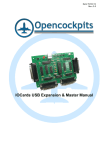
 OPENCOCKPITS IOCards USBLCD INSTALLATION AND USER’S MANUAL INSTALLATION AND USER’S MANUAL v2.1 IOCards USBLCD INTRODUCTION The USBLCD card was designed to manage up to 4 displays LCD compatibles with the standar HD44780. This card have an USB connection and the controller is set managed via IOCP protocol. The software allow to manage up to 20 virtual displays, that will be configured in visual form with the texts an offsets that the user will show on the displays COMPONENTS LIST -
C1, C4, C5, C6 = CAPACITOR 0.1 mF C2, C3 = CAPACITORS 22Pf IC1 = MICROCHIP 16C745 IC2, IC3 = INTEGRATED CIRCUIT 74HC541 J1 = CONNECTOR USB J2 = POWER CONNECTOR 2 PINS J3 = FLAT CABLE CONNECTORS 40 PINS Q1 = QUARTZ CRYSTAL 6MHZ R2, R3 = RESISTORS 10K R1 = RESISTOR 1K5 MANUAL DE INSTALACIÓN Y USO IOCards USBLCD 2 INSTALLATION AND USER’S MANUAL v2.1 IOCards USBLCD PRINCIPAL MEASURES CONNECTORS DESCRIPTION: •
•
•
J1 = USB connector, allows the connection to the PC directly, at the momento that is connected the PC recognizes de card and automatically installs the HID driver J2 = Power connector. J3 = 40 pins connector to wire the multiplexed lines for LCD’s (see figure below) The LCD (Liquid Crystal Display) modules, are compact and needs a few external components to work properly. The principal function of this LCD’s is to show the user desired characters. The modules can be of several measures, they goes from 1 to 4 lines and from 16 to 40 characters for line. On the following images we can see the aspect and position of the pins in an standar module, and also in a backlighted module, the only difference between they is that the backlighted have 2 more pins, that will feed the backlightning MANUAL DE INSTALACIÓN Y USO IOCards USBLCD HOW IT WORKS 3 INSTALLATION AND USER’S MANUAL v2.1 IOCards USBLCD WIRING AND PINS TABLE PIN LCD SISMOLOGY
PIN USB LCD 1 VSS = GND 9 2 VCC = +5v. 10 3 Vee Pot 10K 4 RS 32 5 R/W 9 Display 0 = 29
6 E Display 1 = 30
Display 2 = 27
Display 3 = 28
7 DB0 2 8 DB1 1 9 DB2 4 10 DB3 3 11 DB4 6 12 DB5 5 13 DB6 8 14 DB7 7 This diagram show the wiring for the display 0, to connect the displays 1, 2 y 3, we will repeat the wiring with only one exception, the “E” connection from LCD that will be changed for the pins numbers 30, 27 y 28 respectively from the 40 pins connector, as we can see in the above table of wiring. MANUAL DE INSTALACIÓN Y USO IOCards USBLCD 4 INSTALLATION AND USER’S MANUAL v2.1 IOCards USBLCD SOFTWARE USBLCD To manage the card we can use the two applications programmed to this use: •
IOClcd.exe: is an IOCP client that manages the card through the USB port. •
IOClcd_config.exe: with this application we can create an lcd file, this file have the several configurates for the LCD’s and their associated offsets. IOClcd.exe: First of all we must configure the IOClcd.ini, to allow us to have access to the program, having this file the following parameters: MUSB=No Put on Yes if you have more than a USB card connected on the same PC. deviceUSB=XX In this parameter we configure the number of device that will connect the card (to know this number of device, we can use the application USBCheck, that can be downloaded from www.opencockpits.com/uploads/USBCheck.zip) IOCP_host=localhost This is the addres that the IOCP server will connect (SIOC), if is on the same PC this address can left as “localhost”. IOCP_port=8092 This is the connection port from the above server (by default is 8092, but can be whatever you want). We must tell, that teh IOCP server (usually SIOC), would be on any PC on the net, by this issue the cards can be connected on any of them, inclusive the same PC. Refresh time for LCD screens, by default 80ms. These are all configurable parameters in this application, now, the program when we start it tells us the connection address, if is connected to the IOCP server and if there is a localized and functioning card. Also tells us in that number of device is connected. IOClcd_config.exe: This application is used to configure the several displays and their respective IOCP offsets. Below you can see an image of this program (in it, shows only the first display of the four that we can connect on each card) and with the several elements marked with a letter, let us to describe: MANUAL DE INSTALACIÓN Y USO IOCards USBLCD Refresh=80 5 INSTALLATION AND USER’S MANUAL v2.1 IOCards USBLCD A: This is the number of Display that we have connected (you can see the connection table above), we can connect up to 4, and every one must be a different type. (see B) B: In this field we can choose the type of display that we will use and we have connected, depending of the number of lines and characters for line (there are models that they have two versions due their memory configuration). C: Identification number of virtual displays, we can have up to 5, identified from 0 to 4 and we can call in SIOC, referring to their offset (see D) and their identifier number. D: Number of the offset associated to the display, we will use for to refer in SIOC to the display. To assign this variable we must use the (E) field and the (F) button. E: Here we can introduce the number of offset to assign to the display. F: Click to confirm the variable number on the (E) field. G: Each of the green cells are a character on display, these characters can be configured with plain texto r with IOCP offsets. To introduce those elements we will double‐click on the first cell that will be the first digit/character that we want to introduce. When we double‐click over this cell, appears this window: 1: In this field we will introduce the plain text that we want to show, each character is a place of the LCD and starts from the cell that we was double‐click. To erase the text is enough to write “spaces” as characters we have wrote before, also very time you double‐click on any of this cells you can overwrite the text, simply writing a new text on this field. 2: This button confirms this text input. 3: This field is used to introduce an IOCP offset (accepts any integer number from 1 to 9999) that will be used to represent values on the LCD. MANUAL DE INSTALACIÓN Y USO IOCards USBLCD 6 INSTALLATION AND USER’S MANUAL v2.1 IOCards USBLCD 4: This field shows the length of this IOCP offsets numbered on the (3) field, this length starts from the cell where we have double‐click, as the same on the plain text, showing this on the display hanging the color of the cell from green to yellow. When you roll‐over the mouse on these cells appears a label showing us the number of offset. 5: This button confirms the offsets and length input. 6: Double‐click on the yellow cell, this dialog opens again with this button active, if you click over this button, then the offset number is reset to blank. When you have your virtual displays configured, using the Save option on the application, the file IOClcd.lcd will be created, and this will be used for the controller to manage the display. If we start the file IOClcd.exe now, they will connect to the IOCP server, and the offsets take their values as we have configured and they will show on the display, aligning their values ever to the right. Following we show an example to use these applications. EXAMPLE: For the example we will use a 16 characters and 1 line Display. On it we show the remanent fuel quantitys on the Left, Center and Right tanks, using as we said before the same display and showing it in relation to one three positions switch and on each position od this switch we show any of the tanks. First thing to do is to configure the virtual displays. We run the IOCldc_config.exe application and they shows us the screen where we can configure the several displays, the first one we configure will be the left tank, as you can see on the below image: The (A) field must left as is, because this is the (0) number to that we have do reference on SIOC to call this virtual display, from the three we will create. On the (B) field we introduce the number of variable to that we do reference to call the display =, in our case we use the number 1 (but, can be whatever you want between 1 and 9999, as we explain before) We double‐click on the (C) cell and we write the word “LEFT”, then click on the button to show this Word on Display. Again we will do double‐click on the (D) cell, to introduce the number of offset and the length of the value that we want to appear on the yellow cells. MANUAL DE INSTALACIÓN Y USO IOCards USBLCD 7 INSTALLATION AND USER’S MANUAL v2.1 IOCards USBLCD In our example, we use the offsets and lengths following: OFFSET LENGTH VALUE TO SHOW 1001 2 FUEL LEFT TANK (THOUSANDS PART) 1002 1 FUEL LEFT TANK (HUNDREDS PART) 1003 2 FUEL CENTER TANK (THOUSANDS PART) 1004 1 FUEL CENTER TANK (HUNDREDS PART) 1005 2 FUEL RIGHT TANK (THOUSANDS PART) 1006 1 FUEL RIGHT TANK (HUNDREDS PART) (E) and (F) cell will be filled as on the above fields, the (E) cell includes the “.” between the thousands part and the hundreds part. We have ready our first virtual display, now we can do the following two virtual displays, changing the (A) number, as we can see in the following images, the first one for the center tank: And this for the right tank: MANUAL DE INSTALACIÓN Y USO IOCards USBLCD 8 INSTALLATION AND USER’S MANUAL v2.1 IOCards USBLCD Now we can sabe the configuration as “IOClcd.lcd”, then close this application. We have now the first phase done, now we will proceed with the SIOC script to manage those three virtual displays. This is the script: Var 0001
Var 0002, Link FSUIPC_INOUT, Offset $0B7C, Length 4
{
L0 = V0002 / 128
L1 = L0 / 65536
V0015 = L1 * 10049
}
Var 0003, Link FSUIPC_INOUT, Offset $0B74, Length 4
{
L0 = V0003 / 128
L1 = L0 / 65536
V0016 = L1 * 15495
}
Var 0004, Link FSUIPC_INOUT, Offset $0B94, Length 4
{
L0 = V0004 / 128
L1 = L0 / 65536
V0017 = L1 * 10049
}
Var 0011, Link IOCARD_SW, Input 11
{
IF V0011 = 1
{
V0001 = 1
}
}
Var 0012, Link IOCARD_SW, Input 12
{
IF V0012 = 1
{
V0001 = 2
}
}
Var 0015
{
L0 = V0015 / 100
V1002 = MOD L0 ,10
V1001 = DIV L0 ,10
}
Var 0016
MANUAL DE INSTALACIÓN Y USO IOCards USBLCD Var 0010, Link IOCARD_SW, Input 10
{
IF V0010 = 1
{
V0001 = 0
}
}
9 INSTALLATION AND USER’S MANUAL v2.1 IOCards USBLCD {
L0 = V0016 / 100
V1004 = MOD L0 ,10
V1003 = DIV L0 ,10
}
Var 0017
{
L0 = V0017 / 100
V1006 = MOD L0 ,10
V1005 = DIV L0 ,10
}
Var 1001
Var 1002
Var 1003
Var 1004
Var 1005
Var 1006
We can compile this script into config_sioc.exe and we must save as sioc.ssi The following to do is run Flight Simulator, next IOClcd.exe and last one run the sioc.exe. If we turn the switch and we change it of position, the display will show the different values of fuel quantity on the tanks. To see how it works, we can try to explain the different the lines and their functioning: Var 0001
Var 0010, Link IOCARD_SW, Input 10
{
IF V0010 = 1
{
V0001 = 0
}
}
MANUAL DE INSTALACIÓN Y USO IOCards USBLCD This line defines the offset number 1, that as we see before is the one used to “call” the display and even the value takes, they will show us a virtual display or other (values 0, 1 y 2) 10
Var 0002, Link FSUIPC_INOUT, Offset $0B7C, Length 4
{
L0 = V0002 / 128
L1 = L0 / 65536
V0015 = L1 * 10049
}
This line and their following calculations, is the declaration of the FSUIPC offsets, to take or write FS values, in this case is the one used to know the % of remaining fuel on the left tank. The calculations are to convert this % in a remaining fuel value (in pounds). This same declaration must be done for the others tanks (Var0003 y Var0004) INSTALLATION AND USER’S MANUAL v2.1 IOCards USBLCD Var 0011, Link IOCARD_SW, Input 11
{
IF V0011 = 1
{
V0001 = 1
}
}
Var 0012, Link IOCARD_SW, Input 12
{
IF V0012 = 1
{
V0001 = 2
}
}
This is the declaration of the three positions of the switch, as you can see clearly, those offsets are linked to IOCARD_SW, that is a switch declaration on SIOC and the values for the inputs are the numbers 10, 11 y 12, this must change in your script, taking the value you have connected on your hardware. Var 0015
{
L0 = V0015 / 100
V1002 = MOD L0 ,10
V1001 = DIV L0 ,10
}
Note: Software programs, circuits and content published in this paper and on our website are copyrighted by their developers, who doesn't consent to their use for commercial gain, unless authorized in writing. The software and content published and any code developed can be distributed as often as necessary and through desired media without written authorization, provided that the publication is acknowledged to the author and the source from which comes www.opencockpits.com MANUAL DE INSTALACIÓN Y USO IOCards USBLCD In this case we have a “NO LINKED” offset in SIOC, where we are doing the values calculations and sending to their position on the display. The first we have done, because we want to represent only the thousands and hundreds, is to divide by 100 to obtain the three firsts values and at the same time to send the hundreds value to their offset (MOD divide by the last value (10) and only takes the rest of this division) and the thousands values (DIV divide also this value and takes the integer part). This calculation is done on the three virtual displays. Last thing to do is to declare the virtual displays values, as we remember, this will be used to show the values on the several virtual displays. Those offsets are 1001, 1002, 1003, 1004, 1005 y 1006. 11


