1
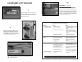
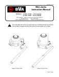
INSTRUCTION MANUAL JL-C Extension Rams PRINTED IN USA 0309 PART NO. 159R125 Rev. 03 ©2009 Hale Products, Inc. Hale Products, Inc. reserves the right to make changes at any time, without notice or obligation, in prices, materials, equipment or specifications and to change or discontinue models. Check with distributor for current information PRODUCT SAFETY POLICY Jaws of Life© products are designed and manufactured to provide excellent service when used for their intended purpose. Operator safety is a major consideration in the product design and operator manuals are provided to promote their safe usage. Additionally, operator training programs are offered by all authorized Jaws of Life Distributors and this company. Hale Products, Inc. urges all users of Jaws of Life products to read the Instruction Manual and to seek operating instructions from qualified instructors before attempting to use the products. Although most safety precautions are addressed in factory authorized training programs, as well as throughout this manual, particular attention is directed to the following: HURST Blue® RESCUE TOOL HYDRAULIC FLUID PRECAUTIONARY MEASURES Avoid contact with eyes, skin and clothing. Avoid breathing vapors. Keep container closed. Use only with adequate ventilation. Wash thoroughly after handling. NOTE: It should not be dumped, spilled, rinsed or washed into sewers for public waterways. Dispose of containers in accordance with local requirements. Emptied container retains vapor and product residue. Observe all labeled safe-guards until container is destroyed. EMERGENCY and FIRST AID PROCEDURES FIRST AID: • Power units and tools should be operated by qualified personnel only. • When removing the tool from a multitool circuit, be sure the other tools are not in use and the dump valve is in the “closed” position before disconnecting unit. • Proper protective clothing should be worn. (i.e. bunker gear, gloves, helmets, face shields, etc.) IF IN EYES, immediately flush with plenty of water for at least 15 minutes. Call a physician. IF ON SKIN, immediately flush with plenty of water. Remove contaminated clothing. Wash clothing before reuse. IF INHALED, remove to fresh air. If breathing is difficult, get medical attention. • Be sure to follow all maintenance procedures. • Inspect the equipment for obvious broken or missing parts or damaged hose before and after each use. • Return your warranty registration card. • Keep clear of all moving parts. NOTES • Use only factory authorized service parts. • When pulling, keep clear of chains. • Use only Hurst Blue® rescue tool hydraulic fluid.* Do not substitute other brands of hydraulic fluid because characteristics may differ. Fluid such as brake fluid or automatic transmission fluid will not work in the Jaws of Life system and will damage the equipment. • When lifting, always use cribbing to shore and stabilize the object being lifted. • When storing tool, compensate for possible pressure buildup from thermal expansion of hydraulic fluid by connecting the two short hoses on the tool, completing the circuit. Move trigger in both directions to equalize the pressure on both sides of the piston. • Ear protection should be worn when operating the 2-cycle and 4-cycle units. HYDRAULIC FLUID: Hurst Blue® rescue tool hydraulic fluid* is a custom blended polyether polyol hydraulic fluid. In case of skin contact, wash off with soap and water. In case of eye contact, flush with generous amounts of running water. If discomfort persists following flushing, see physician for symptomatic treatment. DO NOT OPERATE EQUIPMENT WHEN TIRED, STAY ALERT. *Hurst Blue® - MSDS on file. 1 10 GENERAL MAINTENANCE GENERAL MAINTENANCE GUIDE * DAILY MAINTENANCE/INSPECTION • • • • • • • 6 MONTH MAINTENANCE Inspect carefully for hydraulic leaks Inspect hoses and couplings for wear and damage. Check control valve operation for easy operation and free return to neutral (center). Check cylinder rod for dirt and scoring. Be certain all parts are clean. Check feet for damage. Check that all fasteners (nuts, bolts, screws and retaining rings) are in place and securely fastened. • • Check ram feet for wear and damage. Replace if necessary. • Check hoses and couplings for wear and damage. Replace if necessary. LENGTH: HEIGHT: WIDTH: WEIGHT: 15.00 in. 7.00 in. 3.13 in. 18.10 lbs SPREAD DISTANCE: 7.00 in. HIGHEST SPREADING FORCE: 15,520 lbs. LOWEST SPREADING FORCE: 15,520 lbs. * For Pulling applications, the JL-20C requires Ram Foot Kit #377R294 LENGTH: HEIGHT: WIDTH: WEIGHT: ANNUAL INSPECTION* • Clean tool. Check for wear or damage on all parts. Check that all fasteners (nuts, bolts, screws and retaining rings) are in place and securely fastened. • • • • • STORAGE • • Pressure check all valve and internal seals. Replace as required. JL-20C Part Number 257R095 JL-30C Part Number 257R097 AFTER USE MAINTENANCE • • • • TECHNICAL DATA Protect unit against moisture. Store in adequate space to prevent damage to hoses, connectors or tool itself. CAUTION: Before storage, connect the pigtail hoses to each other and move throttle control in both directions to equalize pressure in system. • Pressure check all valves and internal seals. Replace as required. Check operating pressure, unloaded through full operating cycle. Check ram feet for chips, cracks or other damage. Check opening and closing times. Replace operating decals, if necessary. Replace hoses, couplings and fasteners as required. Clean and lubricate the ram. 23.00 in. 7.00 in. 3.13 in. 24.40 lbs SPREAD DISTANCE: 13.00 in. HIGHEST SPREADING FORCE: 15,320 lbs. LOWEST SPREADING FORCE: 15,320 lbs. HIGHEST PULLING FORCE: 9,087 lbs. LOWEST PULLING FORCE: 9,087 lbs. JL-60C Part Number 257R099 LENGTH: HEIGHT: WIDTH: WEIGHT: 35.00 in. 7.00 in. 3.13 in. 36.40 lbs SPREAD DISTANCE: 25.00 in. HIGHEST SPREADING FORCE: 15,320 lbs. LOWEST SPREADING FORCE: 15,320 lbs. * Call your authorized Jaws of Life Distributor for maintenance and annual inspection care. 9 HIGHEST PULLING FORCE: 9,087 lbs. LOWEST PULLING FORCE: 9,087 lbs. 2 10 ASSEMBLY/STORAGE IMPORTANT: Your ram MUST be registered. Please return the self-addressed warranty card included with your documentation. 1 Should you have to contact us about your ram, refer to the tool serial number (found on the tool as shown). This identification will expedite any service you may require and will also enable us to keep your records current. Remove the Ram from carton. Inspect unit and confirm that all bolts and screws are securely fastened and the unit has not been damaged in shipment. TROUBLESHOOTING GUIDE* 2 PROBLEM CAUSE REMEDY • • Hydraulic Fluid is low • • Air in Hydraulic System • • Valve thumb control lever is loose • • • Low flow from power unit Erratic flow from power unit • • Have power unit repaired. Have power unit repaired. • • Low pressure from power unit Leak in control valve seals • • • Internal seal failure • • Coupling failure • Have power unit repaired. Remove and replace control valve. Have tool repaired with new seals. Remove and replace couplings. • Couplings not properly connected • • • • Coupling failure - fails to open internal check when connected No flow from Power Unit • • Hoses Reversed on power unit Couplings reversed on tool • • • Couplings are not properly connected • Tool operates erratically, slowly or fails to operate. Before connecting the hydraulic hoses, place the power unit by-pass valve in the DUMP position. Please refer to the power unit operation manual for more information on how to operate it if necessary. • • • 3 Connect the hoses from the power unit to the pigtail hoses on the ram as shown. 3 Tool has apparent loss of power Tool fails to operate Hydraulic fluid is leaking from valve/rear handle • Check fluid level in reservoir and add fluids as required Fully open and close tool several times. Tighten or replace screw on thumb control lever, or replace thumb control lever assembly as required. Connect couplings correctly (See page 3, section 4) Remove and replace coupling Check power unit and repair as required. Remove and reverse hoses Remove and reverse couplings Put power unit in DUMP position and connect all couplings properly * Call your authorized Jaws of Life Distributor for maintenance and annual inspection care. 8 7 Lift steering column by retracting the ram. If the steering column has not been pulled far enough away from the victim once the ram has fully retracted, secure the steering column in it’s current position, then extend the ram and shorten the chain length by adjusting the chain at the grab hooks until all slack has been removed. Retract the ram again to move it farther away from the victim. 4 To operate the quick disconnect couplings, align the slot in the sleeve with the pin. Slide the sleeve back to connect or disconnect the coupling, rotate the sleeve 1/4 to 1/2 turn to lock the coupling. 5 If your tool is equipped with Streamline couplings simply twist the couplings counter clockwise to remove tool from the hydraulic circuit. You do not need to put the power unit valve in the dump position. 8 Before attempting to disconnect the ram from the power unit always move the operating lever on the by-pass valve to the DUMP position. 6 9 After use, disconnect the ram from the power unit. Connect the two pigtail hoses on the ram to each other. Protect the unit from moisture or store in a moisture-free location. Secure in adequate storage space to prevent damage to the ram or kinking of the hoses. Start the power unit and move the lever on the by-pass valve to the PRESSURE position. 7 Operate the ram by twisting the actuator handle counter-clockwise to extend the ram and clockwise to retract. If the ram does not operate correctly, make sure the quick disconnects are properly connected (Step 4). If necessary, refer to the Troubleshooting section of this manual. For initial start-up and after service or maintenance, extend and retract the ram several times to purge any air from the system. 7 4 SPREADING/PULLING 4 PULLING 1 To push an auto seat back, insert the ram between a firm surface and the frame of the seat. Twist the actuator handle counter-clockwise to extend the ram and break the seat bracket. 5 2 To attach chain shackles to the ram, slip the shackles over the feet of the ram and insert the long shackle pins through the holes in the feet, locking the shackles into place. To lift a dashboard or steering column, place the stationary foot of the ram at the base of the door opening on the latch side. Extend the ram to make secure contact with the lower side of the dashboard/steering column. Continue extending to displace the dashboard/steering column. NOTE: This procedure only applies to the 30C & 60C rams. 3 To lift a dashboard or steering column with a 20C ram, place the stationary foot of the ram on the floorboard. Extend the ram to make secure contact with the lower side of the dashboard/steering column. Continue extending to displace the dashboard/ steering column. NOTE: Not applicable to JL-20C rams. A. Fully extend ram. B. Place shackles over ends of feet and insert the shackle pins through the shackles. C. Wrap the chain around the steering column and slip hook over chain. D. Attach the other chain to the body frame beneath the car. E. Adjust the chain length at the grab hooks until all slack has been removed from the chain and the ram is resting on the hood of the car. 6 CAUTION: Be certain to attach the chains in the same direction (both hooks facing the same direction) to prevent twisting. 5 6