1
..
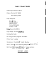
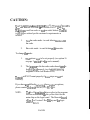
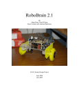
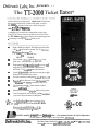
The TT-2000 Ticket Eatera
Deltronic Labs, Inc. presents.
A fully automated, high speed, stand alone Ticket Eater
that counts and destroys tickets and prints a receipt.
TT-2000 £ills big shoes, but has a small footprint:
Only 21"Lx 21'W x 59"H.
A valuable tool to make the redemption process part
of the FUN! The customers feed their own tickets into
the 'IT-2000 and enjoy the display and counting process
- presenting a receipt to redeen~their prizes.
@
High visibility five digit 2 LED display of each ticket
value and total points countetl- 8 to 10 ticlets/sec
Disl7lrl)' s e ~ l l i sr t r r s s n ~ e stoo:
FULL bill
PAPER low
PRINT
ERROR
@
*
@
User friendly ,Thertnal Printer forhst, Crisp
print-outs. (Accepts up to 8" paper roll)
Programmed when matlufactured to accept and
read ONLY your custom bar coded tickets.
OPTION: Can read tlon bar coded ticltets
Can be programtned on location to read up to eight
different bar coded ticket values
Accepts standard redemption ticltets 2"1, x I5/i?W
@
Patetltetl Quick Release Cutter Mechanis~llwith
4 blades in one means, extremely long life!!!
@
No cheating allowed!!! Pull on those tickets
and it subtracts one!
@
Interfaces available for popiilar debit card systems.
Available
230vac
5 0 H z 3Amp
Can be interfaced with existing vending machines
to create Fully automated redemption.
For fu~therdetalls and specs on the excitlng
TT-2000please call SALES at 215-997-8616
i~Jiuiiirlnct~itecI
wili! Pridts i t 1 ii\r>l J S i',
U.S. Patents 5211093 & 5996457
Another quality p r ~ d u cfrom
t
Deltronic Labs.
. . the industry leader in ticket dispensers
For information on our complete line of products, please call
Beltronic Labs, lnc.
120 Liberty Lane, Chalfonf, PA 18914
.
215.997-861 6 FAX tf 215-997-9506
Visit us of our web site: w~.deltroniclobs.com
TABLE OF CONTENTS
General Operation Procedures
Printers Thermal (CITIZEN)
Dot Matrix (STAR)
Entry of Options
Date 8~ Time
Receipt Options
Machine Codes
Setting Full Bucket
Security Levels
Ticket Types (READING)
Paper Length Indicator ("PAPEr")
Entering Bar Codes
Re-setting Counters, Options and Audits
Printer Paper Loading
Maintenance Check List a Trouble Shooting
Motor, Guide
8~
Cutter Assembly Diagrams
-
Detail of Parts
Bar Code PCB Diagrams 8T Details of jumper positions
(Rev.8 or Version 2 Rev 1 a up).
REVISION 6-2003
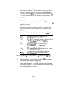
TT-2000 OPERATING PROCEDURE3
REVS. 24M, 24T, 25T & Rev. 3.1 -7T, M& K
Two switches (red and blacklwhite) are located inside the unit. These switches
are on the left side of the lower shelf near the mechanism. The blacklwlute switch
is wired to the front switch. These switches are used in the procedures below to
do an audit, and to set the date, time, options, values, and ticket point values for
new bar codes, and other functions
Printers:
Dot Matrix:- Star Only
Two small switches are mounted to a small PC Board next to the printer
wliich is mounted to the door. There are also three LED'S mounted on the
same board. The top LED is just an 'ON' indicator. Tlus LED is green.
The bottom LED is the 'ON LINE' indicator (also green) and will normally
ttirn on when the unit is turned on. The top switch will turn this LED
alternately on then off if pressed. The other switch will cause the printer
to feed paper. The middle LED (red) will only turn on when the printer
has a problem (such as out of paper).
Thermal:-Citizen Only
There is one small push button switch on the side of printer. Tlus switch
advances the paper through printer. There is a toggle switch next to it. Tlus
is the power switch. Please refer to page 7 in this manual for paper
loading. Refer to PPU-231 users manual for printer care and various
functions.
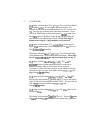
E n t ~ yof Date, Time, and Bar-coded Tickets
I.
Open top door of TT-2000. Pull "Main Safety" switch out. Display will
cycle through test mode. When display returns to "Snake Mode", Push swl
on logic PCB. Display will read 99-0. You are now in "SETUP MODE".
The red "Internal Power" switch must be on.
11.
Note that the display (on the front door) now reads '99 0'. Press and
release the black switch to change the '0' to '1' and then to '2' to '3' and
then back to '0'. Pressing the red switch will have the same result except
the display will display '0' then '3' then '2' then '1' and then back to '0'.
This fact will also be used to set a value. That is, press and release the
black switch to increment the value whereas the red switcll decrements the
value. You must press both switches to accept the value and go to the
next step. .
I11
A. DATE AND TIME
While in the setup mode, the display will read '99 0'. Press both
switches at this time to enter the date and time. Use the red and
black switches to set the values as follows: NOTE: the date and time of
May 16, 1997,2:24 PM is used as an example.
1.
The display should read "1" plus a flashing number, which
is the "century". Change to read '19'. Press both switches
when done.
2.
The display should read "2" plus a flashing number, which is the
"year". Change to read '97'. Press both switches when done.
3.
The display should read "3" plus a flashing number which is the
"month". Change to read '5' for May. Press both switches when
done. Value from 1-12.
4.
The display should read "4" plus a flashing number, which is the
"date". Change to read '16'. Press both switches when done.
Value from 1-31.
5.
The display should read "5" plus a flashing number, which is the
"day". Change to read '2' for Monday. Press both switches when
done. Value from 1-7. ie. l = S w
6.
The display should read "6" plus a flashing number, wluch is the
"hour". Change to read '14' for 2 PM. Press both switches.
7.
The display should read "7" plus a flashing number, which is the
"minute". Change to read '24'. Press both switches when done.
Value can be set from 0-59. At this time, the seconds are set to '0'
and all the information is saved. The display will go back to '99 0'.
B.
OPTIONS
While in the setup mode, the display will read '99 0'. Increment
the display to read '99 1'. Press both switches at this time to set the
options as follows:
The display will now show '10 x' (x='Ot or '1'). Press the red or
black I white switch to set the options in the list below to either
'0' or '1'.
Display
x=Oorl
'lox'
'11 x'
'12 x'
'13 x'
'14 x'
'15 x'
'16 x'
' 17x'
Description of Options Revisions 3.1K & 7K
l/O=print/don't print serial # on receipt
O/l=print time in 12 / 24 hour format
O/l=dis/enable dual rear sensors (112 ticket detect)
Rev 3.1K- O=error detect lsec 1= l0sec.
O/l=dis/enable printing barcode on receipt
O/l=dis/enable look for holes in tickets
O/l=dis/enable sending cl~ecksumdigit in
(1st machine code digit dropped if enabled)
Oll=barcodekoles-only operation- Note: Jumpers
on BCR-1000 must be changed to switch from
reading holes or reading barcodes on tickets
O/l=dis/enable print text below barcode
NOTE: Options 16 & 17 used in Revs 25T & Version 2 Rev. 1 K & Up.
C.
Machine number, minimum tickets required, fill1 bucket setting,
error adjust, paper length setting & audits.
While in the setup mode, the display will read '99 0'. Increment
the display to read '99 2'. Press both switches at this time to adjust
the values mentioned as follows:
PAGE 3
C.
(CONTINUED):
The display will now show '20 n' (n=O-9). Then is the first digit of
the machine number. Set this digit to the desired value. For
example, if you want the machine number to be '123' set this value
to 1. Press the two switches at the same time when done. (Note:
This is the FIRST digit in the barcode printed on the receipt if the
check suill option is disabled. If this option is enabled then this
digit will not be included in the barcode. NOTE: This digit is
dropped on receipt if a 3 digit machine code is desired.
The display will now show '21 n' (n=0-9). The n is the second
digit of the machine code. In the example above set the value to 2.
Press both switcl~eswhen done.
The display will now show '22 n' (n=O-9). Then is the third digit
of the machine code. Press both switches when done. Three digit
Max in V2R3.1K. V2R7K has optional fourth digit (see pg. 5)
The display will now show '23nn' (nn=I-99). The 1111is the
minimum number of points required so that a receipt can be
printed. Example, if this is set to 5 then at least 5 points
(5 tickets of 1 point value) have to show on the display before the
customer can get a receipt. Press both switches. (V2R3.1K) See
Page 5 for V2R7K Settings
The display will now show '24nn' (nn=l-99)l The nn is the full
bucket value in thousands. Tly setting this to 25 for 25,000 tickets.
After 25,000 tickets the display will read 'FULL'. The unit will not
take in any more tickets until reset. (V2R3.1K) See
5 for V2R7K setting.
The display will now show '25nn' (nn=l to 99). This option is not
used at this time.
The display will now show '26nn' (nn=I to 99). This sets the value
of ticket for holes only operation. Press both switches when done
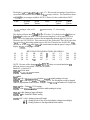
The display will now sl~ow'27nn' (nn=O to 17). This sets the percentage of good tickets
versus bad tickets that the unit will accept from a strip of tickets. The chart below shows
an example of percentages available: NOTE: Effective for bar-coded tickets ONLY.
Value
% Good
% Bad
Value
% Good
% Bad
0
Tickets
100
Tickets
0
17
Tickets
10
Tickets
90
Factoly setting is value of 10.
O= most security 17= less security
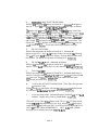
The display will now show '281~1'(nn=O to FF in hex). Use the hex code chart below to
deternline the value you need. This value sets the length of a roll of paper in 10 foot
units. The roll of paper that is sent out for the unit using thermal paper is 1105 feet.
Therefore use 110 (1105110). This converts to 6E hex in the table. The roll of paper that
is seut out for the unit using regular paper is 485 feet. Therefore use 48 (485110). This
converts to 30 hex in the table. When the unit determines that the paper is empty, it will
display "PAPEr". See page 6 or 6A.
40
41
42
43
28
29
2A
2B
HEX CODE CONVERSION TABLE EXAMPLES
8E
193
Cl
91
6B
142
8F
194
C2
92
6C
143
93
6D
144
90
195
C3
*6E
145
91
196
C4
94
244
245
246
247
F4
F5
F6
F7
NOTE: Because of the changes nlade in REV.7K there are certain banks that are
different and new ones added. These are as follows:
Bank# 99-1, Option # 12
V2R3.1K is Error detect
V2R7K is enableldisable rear sensors
Balk# 99-2
V2R3.1K # 23 = Mininlu~nnumber of tickets inse~tedto enable printing of receipt.
V2R7K # 23 = 4th digit in mach, code nuniber. NOTE: The first digit on receipt is dropped
when a 3 digit machine code is desired. Example: Use "21-"nnas first number of a 3 digit code.
V2R3.1K # 24 = Ticket Bin "FULL setting.
V2R7K # 24 = Mininlu~nru~mberof ticket to enable printing of receipt.
V2R3.1K # 28= Setting of paper roll length.
V2R7K # 28= Ticket Bin "FULL" setting.
V2R7K ONLY # 29 = Setting of paper roll length.
# 30 = Setting for use of four or five digit display (change # accordingly)
# 3 1 = Setting for three or four digit machine code number.
D.
ENTERWG NEW TICKET BARCODES
Wliile in the setup mode, the display will read '99 0'. Incretne~itthe display to
read '99 3'. Press both switches at this time to learo new bar codes as follows:
(V2R3.1K & V2R7K)
The display will now read '31nn' (i~n=O-99).The 1111is tlle point value of the
ticket. Pressing and releasing both switches will cause the display to go to '321111'
etc. up to '38nn' for up to 8 ticket slots. Go to the first 'available' position ("3 1"
or the first ticket learned). Set tlte point value for the new ticket. Tlien inse~tat
least 7 tickets into the ticket slot. The tnotor will him on to take in the tickets
and 'LEARN' the new barcode, and then stop. Reinove ally extra tickets. The
display will now show tlie data read. Write down this information ill case you
need to contact the factoiy. Press and release hoth switches to accept.
E.
RE-SET COUNTERS:
While in the setup mode, the display will read '99 0'. Increment the
display to read '99 4'. Press hot11 switches at this time and do the following:
Tlie unit will go to a noti flashing '99 4' display. Press the RED switch to reset
tlie counters. The display will go back to a flashing 99 4'. (V2R3.1K)
F.
RE-SET "PAPr" mode: (Indicated on Display)
Wliile in the setup mode, the display will read '99 0'. Incre~nenttlle display to
read '99 5' press both switches to re-set the value for a new roll.(V2R3.1K)
G.
To Print AUDIT:
Wliile in tlie setup mode, the display will read '99 0'. Increment the display to
read '99 6' and press hoth switches to print the total t~u~nber
of tickets counted
since last re-set. The time, date and machine code number will also print.
Tlle unit will go back to '99 0'. (V2R3.1K)
H.
To Print info of LAST TRANSACTION: (Time, Date, Receipt value
& Machine Code)
Wliile in setup mode, the display will read 99-0. Iticreinent the display to read
99-7 and press hot11 switcl~esto print tlie information. (V2R3.1K)
1.
To Escape Setup mode: Increment display to read 99-8 and press both
switches. Display will go back to "Snake Mode" (V2R3.1K)
J. RE-SET "FULL" Bin: When display reads "FULL", the TT-2000 will not
accept any no re tickets and must be re-set. A sw. directly under left side of
switch bracket on shelf will reset "Full" CAUTION: PRESS RED SWITCH
ONLY IF TICKET BIN IS EMPTIED!!!!!!! REV. 3.1K AND UNDER.
See page 6-A for details on revision V2R7K,T &M.
PAGE 6
For use \\,it11 TT-2000 Ticket Eater purchased after 6-15-2003. Unit contains a 5 digit LED display
ATTENTION:
Functions and features of V2R7(.2)K Software
The V2R7K software uses slightly different commands and functions then prior revisions.
These differences are listed below. (See yellow label on prom for Rev. number)
The "Functions" mode is similar to the "setup" mode described earlier in this manual.
A. To Enter Functions Mode:
1. Open top door of Ticket Eater.
2. Reach through hole in logic PCB cover, press SWI and hold.
3. Pull "Main Safety" switch out and release SW1. Display will read "FUnC -X
(X= 0-5)
To choose function to be performed, use Black or Red push button to change function #.
When desired function number is chosen, press SW1 to execute the command.
"FUnC" O= Return to Attract Mode. "Snake"
"FUnC" 1= Print Duplicate Receipt.
"FUnC" 2= Print Audit of total tickets inserted. Total is first number printed.
"FUnC" 3= Manual Printer Paper Reset. Use only if paper is replaced before "PAPEr"
message displayed.
"FUnC" 4= Manual "FULL" Ticket bin Reset. Use only if bin is emptied before "Full"
message is displayed.
"FUnC" 5= Print Options and Settings List.
B. The Red push button in this version software has multi-functions. Pressing the
button when no message is displayed will have no function. The button will reset the
following messages ONLY when displayed.
1. When display reads "FULL" press Red button after ticket bin is emptied. Note: The
ticket bin should ALWAYS be emptied after display reads "FULL" and is reset.
2. When display reads "PAPEr"press Red button after a new roll of paper is inserted.
(switch is niarked with label for functions)
Follow steps on pages 1 through 6 for option settings and "Setup Mode".
NOTE: There are variations of option banks for different revisions of sofhvare.
These differences are noted in the appropriate areas listed in this manual.
PAGE 7
CAUTION
Upon receiving ally new program chips or logic PCB's wit11
new chips containing the following revisions:
C.
24T
D.
24M
F.
Version 2 Rev. 1 Through 7 T, M &K
NOTE: revisions are
marked on the chips
(Yellow Sticker)
The paper low indicator and "FULL" bin are pre-set. After
inserting new program you MUST:
A.
Replace paper with new roll
B.
Empty ticket bin
For 7" to 8" paper roll, the low indicator is set to 1150 ft. For
a 4 112" roll, it is set 485 fi. These lengths are approximate
and the settings can be changed in the field. Refer to
operating instructions or call Deltronic Labs at
(215) 997-8616.
PAGE 8
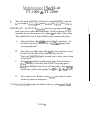
Maintenance Cl~eclcList
TT-1000 & TT-2000
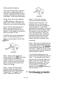
I.
When the guide assembly is released or entire assenlbly is removed
Ibr servicing or clcn~~ing,
Lhc proper ~nclhodLo rcplncc is as lbllows:
IMPORTANT: The MOTOR assenlbly has extra "0" rings installed on
both Lower drive roller and motor shafts. Before replacing GUIDE
assembly, be sure the rings are not "riding" on the sides of the rollers.
They should be far left or right of Roller ends, towards side plates.
A.
B.
C.
D.
Align both idler roller
with slots ill the side plates. At
the same time the (4) pins on side of mech are aligned with
corresponding slots.
First, place rear Idler roller shaft into it's slots (closest to cutter)
.Second, let front idler roller shaft drop into it's slot
Third, pull assembly slightly towards you to allow pins to drop
in their slots.
Push entire assembly forward until it stops (Toward Cutter)).
When assembly is forward, push DOWN on spring spacer
bloclc (has Phillips head screws), to load springs. Rear spriilgs
should loclc in slots with springs. See pgs. 15 Sr 16 f o r details.
Close chute cover. Replace cutter (malce sure cutter is seated
all the way down to mesh gears.
**See Accon~panyingdrawings for details of motor, guide asseillblies &
PAGE 9
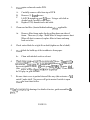
Clean optos on barcode reader PCB.
2.
Carefully remove cable from top of PCB.
Remove (2) thumb screws.
Lift PCB straight up, and tusn over. Using a soft cloth or
alcohol swab, carefully wipe optos.
Replace PCB, thumb screws and cable.
A.
B.
C.
D.
Clean rear fan filter (located behind cabinet )when applicable.
3.
Remove filter frame under fan by pulling down on sides of
frame. There are (4) clips. Shalte filter or bang to remove dust.
When all dust is removed, replace filter to frame and snap
back on to fan.
A.
4.
Check cutter blade for a tight fit on shaft (tighten on flat of shaft).
5.
Check blade for build-up of dirt or adhesive from paper.
Clean with alcohol swab or solvent.
A.
6.
;
Check:large,.gearfor a.tight.fit:on.motor:shaft:
Note: :.Thereare:(2) :
set.screws on largecgear.. #l:holds RPM regulator,to .hub (this screw
does not,tighten to shaft): #2holds gear w1RP.M reg:to motor shaft
(this screw'will bealigned.wit1~
screw'~inpul1eygear). There should
be NO play in gear on shaft.
8
7.
Be sure chute cover is pushed down all the way (this activates a "ltill
switch" under shelf. No power will get to motor if switch is open.
Checlc for bent chute below.
'K4:SeeAccon~panyingdrawings for details of motor, guide assemblies &
parts.":"
PAGE 10
8.
Keep entire shelf area clean of dust. Optos nlay be affected the nlost
fsom dust build-up. Note: While cleaning unit, TURN POWER
OFF. Do not use a inetal end vacuum to clean any PCB's. A can of
conlpressed air will do the job (or compressor).
9
Do not bloclr exhaust fan on rear and right side of unit. If placing
near n wall or any other ol?ject, allow jahiat 6 in. fro111it.
10. Enlpty trash bin wile11display reads "FULL" press either re-set
switch. If bin is einptied erratically the full co~untwill be disrupted. If trash
disposal is scheduled otherwise, i s . . Shift changes etc. Counter can be
re-set at any time. "Rev.24 or Version2 Revl-2. NOTE: Version2Rev3,
bin will re-set anytime either re-set switch is pressed. No audit will print.
"Paper low" indication is set to specific paper roll lengths. When
display reads "PAPI" replace with new roll and in program mode set
display to read 99-5 press both switches to re-set, close door & power up.
11.
12.
Printer probleins are indicated by display reading "PErr".
A.
B.
C.
D.
E.
Paper jam in printer (Not exit plate).
Printer goes off line.
Loss of power.
Data not being received.
Incorrect loading of paper- out of paper
Note: When printer experiences power loss or goes off line, unit must be
powered down & up.
13.Constant "0"or no stast indicates ticltets in guide or in ent~anceblock.
A.
B.
C.
Reinove ticlet(s) from entrance bloclr. Display will
show ticlcet count, re-insert ticltets.
Turn power off to motor assembly. TURN LARGE
GEAR IN REVERSE. Ticltets will appear at entrance.
If necessary, remove Barcode PCB & Guide asseillbly.
(see important replacenlent instructions for guide assy.
PG 15). Relnove ticltets, replace PCB & Assy.
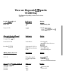
Page 1 I
There are Diagnostie LED'S on the
TT-2000 Tray
Number varies depending on model and revisions
Logic Bonrcl Rev5
Indicates
Status
Red L.E.D.
+5 V
-Both normally ON
*If OFF, check power
switch, 2.25AMP SB Fuse &
connections
Green L.E.D.
Barcode Reader BorcrcE
Indicates
Status
Front Red L.E.D.
Ticket Detect
Rear Red L.E.D.(s)
Ticket jam if L.E.D. is
OFF while mechanism
is idle.
-Normally ON
-Turns OFF when tickets are
inserted.
-Normally ON
-Turns OFF when
tickets are being cut.
Motor Drive Board
Indicates
Status
1 L.E.D.
Motor drive signal
from the logic board
-Normally OFF
-Turns ON when
tickets are inserted-motor runs.
Power Sz~vplvPCB - 9000 PS
Iiz dicntes
status
(HO-1000 PCB)
Version 2 Rev. I& UP
Model TT-2000 Only
Model TT-1000 Only
1 L.E.D.
2 L.E.D.
3 L.E.D.
-All normally ON
continuously.
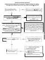
TROUBLE SHOOTING FLOWCHART
OPEN DOOR AND POWER ON BY PULLING OUT THE WHITE INTERLOCK SWITCH
Red toggle switch supplies power to the Printer, Motor Assembly & Logic PCB
On the Logic Board is the
Red and Green L.E.D. "ON"?
Check power sw, 5A & 2.25A S.B. fuse.
Connections to and from power supply.
YES
I
Check connections between Logic PCB,
printer and the display. Make sure that
- the paper is loaded properly into the
printer.
Check display "PERR
LN
Does the display go to "00000-99999 and
then goes to "Snake Mode"?
Insert a ticket and hold under "Ticket detect"
sensor. Does the front Red L.E.D. turn "OFF"
and the rear L.E.D. remain "ON"?
(Reader PCB)
N0TE:lf ticket is held under front sensor for 10 seconds, "TERR or constant "0" will display.
Remove ticket to resume ops. "TERR also
indicates tickets stop in guide track.
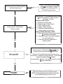
Does the Motor drive L.E.D turn "ON"?
Does the Motor run when
ticket is inserted?
Check connections between the Barcode board
and the Logic board. If the rear L.E.D. is "OFF"
power off the TT-2000 and remove Barcode
board. Check for ticket jam or debris. Remove
the guide assembly if necessary, clear tickets.
Carefully reposition and then re-test. Check
sensor position.
Check the connection between the
Logic and the Motor Drive board
W/ seperate drive PCB only.
CHECK THE FOLLOWING
1 The chute cover is closed.
2. The Motor Safety switch
(located below the chute cover)
3. 2.25 & 5 Amp Fuses
4. The connection between the driver board
and the motor.
5. Front sensor for dust or positioning.
Check: Front sensor positioning &
leads & drive transistor. Power
Supply for 5V to Barcode PCB.
Blocked Entrance block.
Does the motor run before inserting
tickets (At power-up)?
Insert a strip of 10-20 tickets.
Does it cut OK?
-
YES
Power off the TT-2000 and remove the Cutter
& Guide assemblies. Clean and then
reposition. Re-test.
Remove cutter, check:
A. Build-up on blade edge
B. Blade is tight on flat of shaft
C. Gear is tight on shaft
D. Paper in cutter housing
E. Stationary blade adjustment
F. Proper seating of cutter assy.
Remove Guide Assembly, check:
A. Roller springs must have proper tension
& mounting screws tight.
B. Top guide "finger" should be straight in
line with guide track.
C. Clear any paper in guide track or
entrance block.
No count at all, try "Relearning" Barcoded ticket.
Check options for ticket values & ticket style.
ONO1
Miscount? Clean Barcode sensor, blow out any
excess dust. Reposition guide assembly. Check roller
springs for proper shape & tension
(see drawings). Re-test. See section above for cutter
& guide assemblies
Did it count OK?
YES
Print OK?
NO--
Make sure that the paper is loaded properly.
NOTE: Thermal paper is only printed on one side.
(Check paper loading in manual. pg 7)
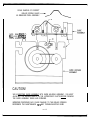
SCALE SAMPLE OF CORRECT
ROLLER SPRING SHAPE
AS REMOVED FROM ASSEMBLY
-
NOTE: REAR PINS (*)
WlLL LOCK WlTH SIDE
PLATE SPRINGS (**)
CAUTION!
W E N INSERTING GUIDE ASSEMBLY INTO GUIDE HOUSING ASSEMBLY, YOU MUST
ALIGN M E TOP ROLLER SHAFTS IN THE APPROPRIATE SLOTS BEFORE PUSHING
THE GUIDE ASSEMBLY DOWN AND FORWARD.
IMPROPER PROCEDURE MAY CAUSE DAMAGE TO THE ROLLER SPRINGS.
REFERENCE THE MAINTENANCE TIPS AND TROUBLESHOOTING GUIDE.
PG. 15
I
REV OATE
I
/ OESCRIPnON
DRAW< 0AIC
10/17/02
Do/&flic Labs,IWC.
faLh$-fmaauncPA
I
MPR
PG. 18
OAE
-
C0,*P"1ul WMIUCS
ruruN mrvlas
RESmlCW
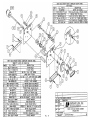
nmrr EATER CUTER
ASSEMBLY
E X P L O O MRV
~
~m-nzooo//
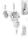
NOTE: ITEMS 16 (THUMB SCREWS) AND 17 (PRINTED CIRCUIT BOARD)
ARE NOT INCLUDED IN ASSEMBLY.
I
I
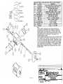
1 10/17/021 REVISED & REDRASN
RN I DATE 1 DESCRIPTION
13
OAK
WO( DATE
WPR
DAIE
Deltronic Labs, lnc. .
I20Libony Lone. Cholfonl PA
TICKET EATER GUIDE ASSEIABLY
EXPLODED t'IEVl
.
1
SHFT- IDLRLR/TE
5 2 BRNG-F3 IZ/TT/BRAS
6 1
ROLR- IDLERITE
4
TE IDLER ROLLER SHAFT
FLANGED BRONZE BEARING
l DLER ROLLER
-
RFILL%R ASSM,
EXPLODED VIEW
DRAWN BY
DATE1
,
PG. 20
..,...........".
QF\11?7rlNT~
2/2/00
,
!
CAUTION:
Thc TT-a000 Ticltel Ealcr prograin (Rcv 25 or Version 2 RCV1 K
Sr up and Barcode PCB Rev. S or Version 2 Rev 1 Sr up) has
the oplion to read bar-codes or no11 bar coded ticlcets. The unil
is shippcd as ordered per the customer's requirements as
follows:
1.
Non bar-code mode: to read ticlcets that have no
bar code.
2.
Bar code mode: to read ticlcets wit11 barcodes.
To change the mode:
1.
The options need to be set properly (see option 16
on page 3 sectioil B in the user's manual).
2.
The jul~lperson the bar code reader board need to
be cotlfigured properly (see the accon~pai~yiilg
diagrams of Bar code Reader PCB).
The unit will NOT count properly if tllese steps are not set
correctly.
If you have ally difficulty selecting these nlodes or options,
please contact Deltronic Labs at (2 15) 997-8616.
NOTE:
The Rev.25 nlentioned above refers to the program
revision as annotated on the yellow label on the
main chip on the logic board. The Barcode board
is Rev.8 or Version 2 Rev 1 6c up and the logic
board is Rev.5.
PAGE 21
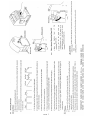
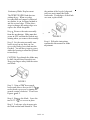
Stationary Blade Adjustment
A
The TICKET EATER blade is adjusted
at the factory. Blade wear will occur
over time. Adjusting the blade so that it
is closer to the cutter will extend the life
of the blade. Follow these simple steps:
FIGURE 2
Step 1. Remove the cutter assembly
from the mechanism. Make sure that
power is OFF and that the blade is not
rotating when you remove the assembly.
,
Step 2. Set the cutter assembly on a
bench in such a way that you can
access the blade screws and turn the
flywheel. Use the edge of your bench to
allow the housing to lie flat.
CAUTION: Even though the blade may
be dull, it is still sharp enough to cut.
Keep your fingers away from the cutter
.;and blade.
Step 5. Turning the set screw
clockwise will cause the blade to
advance closer to the cutter. The
procedure is to turn the set screw
clockwise while spinning the flywheel
slowly towards you. As the blade
approaches the cutter edge, you should
start to hear and feel the cutter contact
the blade as you spin the flywheel. If
you turn the set screw in too far, the
cutter will not spin freely. Repeat the
procedure with the set screw on the
right until you get an even contact
between the cutter and blade, all the
way across.
Step 6 . When you are satisfied with the
contact being made between the cutter
and the blade, begin to tighten the.two
socket head cap screws with the 7/64"
hex wrench. Tighten just a little on each
side and continue to spin the flywheel to
check the blade to cutter fit.
FIGURE 1
You will find that tightening the cap
screws will pull the blade away from the
cutter. To compensate for this, adjust
the set screws to allow the blade to run
tighter to the cutter and proceed with
tightening the cap screws. When you
have the cap screws tightened, you
should still have a slight contact
between the cutter and blade when you
spin the flywheel.
Step 3. Using a 7/64" hex wrench,
loosen the two #6-32 X 318" socket head
cap screws by turning the wrench
counter-clockwise. Do not remove the
screws. Loosen them to the point that
they can be turned with fingers alone.
Please see Figure 1.
Step 4. Using a 1/16" hex wrench,
insert the wrench through the top
clearance hole in the stationary blade. .
Engage the #6-32 X X" socket set
screw. Please refer to Figure 2.
I
;
,
PAGE 22
Reinstall the cutter assembly into the
mechanism. (see pg.16 in manual)
Stationary Blade Replacement
the position of the beveled edge and
take care not to install the blade
backwards. If both edges of the blade
are worn, replace blade.
The TICKET EATER blade has two
cutting edges. When one edge
becomes dull and cannot be adjusted
any further, it can be flipped around to
use the second edge. Follow these
steps to change the cutting edge or to
replace the blade altogether.
Step I.Remove the cutter assembly
from the mechanism. Make sure that
power is OFF and that the blade is not
rotating when you remove the assembly.
Step 2. Set the cutter assembly on a
bench in such a way that you can
a c c e s s the blade screws and turn the
flywheel. You will have to put a spacer
under the housing t o allow the flywheel
to turn freely.
CAUTION: Even though the blade may
b e dull, it is still sharp enough to cut.
Keep your fingers away from the cutter
and blade.
FIGURE 1
Step 3. Using a 7/64" hex wrench,
loosen and remove the two #6-32 X 318
socket head cap screws by turning the
wrench counter-clockwise. Please see
Figures 'I and 2.
Step 4. Remove the blade. Leave the
two #6-32 X 1/4" s e t screws in place.
Step 5. If only o n e edge is worn, spin
t h e blade around and reinstall it. Note
PAGE 2 3
FIGURE 2
Step 6. Follow the instructions
contained in this manual for blade
adjustment.
'
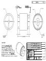
CLAMP DISK
(96-32SHCS SCREW)
CLAMP DISK
(66-32 SHCS SCREW)
I
OUTPUT
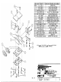
IMPORTANT!
MOTOR DRIVE CLUTCH
PART # RM-CLUTCH/TT
CLUTCH FOR T T 2 0 0 0
Clamp Disks m t l s t bc tigltt.
Tightcn one side at n time.
Partially tighten.one screw,
then the othcr. BE SURE there
is equal distance between top and
bottom portions of clamp when both
screws are tight. (SEE DRAWING)
klotor shaft and drive shaft must be
aligned properly when clutch is inserted.
o Utd.iSSDEER\VlSE
SLIP COUPLING
b SPECIFIED DIUENSICNS
t? MEDl INCHES.
b'An
TOIEWCES
m
*
.
c
G
5
.XX*.o2
WISH
AItGLE X'tS:
XX't.5
F M N G AUUEEA
z
OFU\YN DATE
SCZLE
--
@
Ei
PG. 24
G. A. 6-6-2001
3:2
S?-2027-MI
-.
-. .-
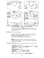
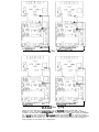
NOTE: For HO- 1000 Rev.4 OP2 = Position l,OP3 = Position 2
For BCR-1000 Rev.3 OP1, Use Position 1 or 2
For Ticket guide assemblies with OVAL cutouts use Position 1 or 2.
For Ticket guide assemblies with ROUND cutouts use: Position 1 ONLY.
(Middle Sensors Only)
IMPORTANT: For Sensor Replacement:
Scanner PCB's BCR-1000 Rev. 2 & 3 and HO-1000 Rev. 4, have sensor
"L"bracket mounting holes marked "A" (Marked on drawing only)
Use only when replacing middle or rear sensors.
Other sensors use PCB mounted "studs" to brace sensors.
When replacing sensors, note Rev.# on PCB. If mounting holes do not
exist, remove brackets before mounting. (Insert sensors to same depth
and direction as all others).
SENSOR PLACEMENT: Each scanner PCB has specific sensors in certain locations.
For HO-1000- All Revs. USE:
VTR16DI- ("V" shaped Lens) OP4 and OP5 ONLY (can be used in OP1)
QRB1114- (Flat Lens) 0P1 and OP2-3 ONLY
For BCR-1000- A11 Revs. USE:
VTR16Dl- ("V" shaped Lens) OP2,OP4 and OP5
QRB1114- (Flat Lens) Can be used in OP2 ONLY
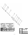
NOTE: For BCR-1000 PCB, All Revs. OP1 is OTC6SO ONLY
The c o n f , ~ u r o t ! o n
above is foi- holes
only opero.tion.
I
I
The configuratton above
t i c k e t s w ~ i l - , barcodes
16
for
1s
For
I
BCR 100 0 Rev. 1
The r o n f i ~ u r a t ~ oabove
n
is f o r holes
onlv ooera.tion.
,
.
I
I
T h e r o n f i ~ t r r a l t o nabove
tlckets with barcodes.
I
1
BCRlOOO Rev. 3-r)
Above a r e t h e d i f f e r e n t configurations f o r t h e 8CR1000 t i c k e t r e a d e r PCB. Two
different r e v s , a r e shown (V2R1 & V2R3). B o t h r e v s a r e intended f o r nornally reading
t i c k e t s w i t h barcodes ( r i g h t confi uration). The holes only confi uration ( l e f t ) is intended
f o r temporary use, such a s when nrcoded t i c k e t s a r e unavailab e f o r a s h o r t period,
F o r a n o r e pernanent situation, t h e HO-1000 b o a r d should be used f o r holes only operation.
Also n o t e t h a t t h e options f o r t h e c o n t r o l unit o r i t s p r o g r a n need t o b e changed t o
work p r o p e r l y in t h e holes only configuration.
E
a
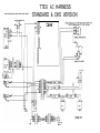
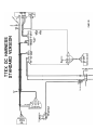
NOTE: WIRE COVERS ARE CLEAR EXCEPT WERE NOTED
TTEX AC HARNESS
STANDARD & DKS VERSION
SWITCH UNDER SHELF
POWER SUPPLY
MOO. GLC750
PAGE 27