1
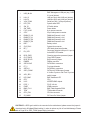
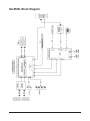
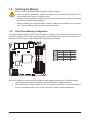
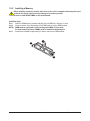
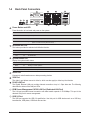
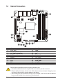
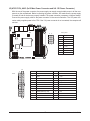
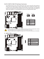
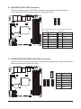
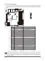
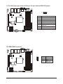
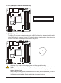
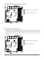
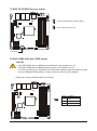
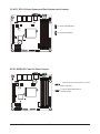
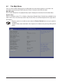
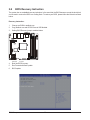
GA-9SISL Intel® Atom® processor motherboard User's Manual Rev. 1001 Copyright © 2014 GIGA-BYTE TECHNOLOGY CO., LTD. All rights reserved. The trademarks mentioned in this manual are legally registered to their respective owners. Disclaimer Information in this manual is protected by copyright laws and is the property of GIGABYTE. Changes to the specifications and features in this manual may be made by GIGABYTE without prior notice. No part of this manual may be reproduced, copied, translated, transmitted, or published in any form or by any means without GIGABYTE's prior written permission. Documentation Classifications In order to assist in the use of this product, GIGABYTE provides the following types of documentations: For detailed product information, carefully read the User's Manual. For product-related information, check on our website at: http://www.gigabyte.com Table of Contents Box Contents....................................................................................................................5 GA-9SISL Motherboard Layout........................................................................................6 GA-9SISL Block Diagram.................................................................................................8 Chapter 1 Hardware Installation......................................................................................9 1-1 1-2 1-3 Installation Precautions..................................................................................... 9 Product Specifications..................................................................................... 10 Installing the Memory...................................................................................... 12 1-3-1 1-3-2 1-4 1-5 Dual Channel Memory Configuration......................................................................12 Installing a Memory ................................................................................................13 Back Panel Connectors................................................................................... 14 Internal Connectors......................................................................................... 16 Chapter 2 BIOS Setup...................................................................................................27 2-1 2-2 The Main Menu............................................................................................... 29 Advanced Menu.............................................................................................. 31 2-2-1 2-2-2 2-2-2-1 2-2-2-2 2-2-3 2-2-4 2-2-5 2-2-6 2-2-7 2-2-8 2-2-9 2-2-10 2-2-11 2-3 Serial Port Console Redirection..............................................................................32 PCI Subsystem Settings..........................................................................................36 PCI Express Settings...............................................................................................38 PCI Express GEN 2 Settings...................................................................................40 Network Stack.........................................................................................................42 CSM Configuration..................................................................................................43 Post Report Configuration.......................................................................................45 Trusted Computing..................................................................................................46 USB Configuration...................................................................................................47 Chipset Configuration..............................................................................................49 iSCSI Configuration.................................................................................................50 Intel (R) Ethernet Connection I354..........................................................................51 Driver health ...........................................................................................................53 Intel RC Setup Menu....................................................................................... 54 2-3-1 2-3-2 2-3-3 2-3-4 2-3-4-1 2-3-4-2 2-3-5 2-3-5-1 Processor Configuration..........................................................................................55 Network Configuration.............................................................................................58 North Bridge Chipset Configuration.........................................................................59 South Bridge Chipset Configuration........................................................................61 SATA Configuration.................................................................................................62 PCI Express Ports Configuration.............................................................................65 System Event Log...................................................................................................66 Memory Event Log..................................................................................................67 -3- 2-3-5-2 PCIe Event Log.......................................................................................................68 2-3-5-3 Whea Settings.........................................................................................................69 2-4 Server Management Menu.............................................................................. 70 2-4-1 2-4-2 2-4-3 2-5 System Event Log...................................................................................................71 View FRU Information.............................................................................................72 BMC network configuration.....................................................................................73 Security Menu................................................................................................. 74 2-5-1 Secure Boot menu ..................................................................................................75 2-5-1-1 Key Management ..................................................................................................76 2-6 2-7 2-8 2-9 Boot Menu....................................................................................................... 78 Save & Exit Menu............................................................................................ 80 BIOS Beep Codes........................................................................................... 81 BIOS Recovery Instruction.............................................................................. 82 Chapter 3 Appendix.......................................................................................................83 3-1 Regulatory Statements.................................................................................... 83 -4- Box Contents Motherboard Driver CD Two SATA cables I/O Shield • The box contents above are for reference only and the actual items shall depend on the product package you obtain. The box contents are subject to change without notice. • The motherboard image is for reference only. -5- GA-9SISL Motherboard Layout 1 2 3 5 6 7 4 8 33 35 34 32 30 28 31 29 24 25 27 26 9 14 23 22 21 20 19 17 16 15 18 -6- 13 12 10 11 Item Code 1 USB_MLAN 2 3 4 5 6 7 8 9 10 11 12 13 14 15 16 LAN1_2 LAN3_4 VGA_COM1 LED_STA SW_ID SW_PWR P12V_AUX1 ATX1 DIMM_P0_A0 DIMM_P0_A1 DIMM_P0_B0 DIMM_P0_B0 BAT1 SYS_FAN1 BP_1 17 PH_LED 18 19 20 21 22 23 24 25 BIOS_PWD CLR_CMOS BIOS_RCVR PMBUS SATA2/3/4/5 FP_2 SATA0/1 SATA_DOM0 26 ACK_SEL1 27 28 29 30 31 32 33 34 35 LED_BMC CPU U351 PCIE_1 IPMB BMC_FLH1 TPM CPU_FAN S3_MASK Description BMC Management LAN port (top) / USB 2.0 ports (bottom) LAN1port (top) and LAN2 port (bottom) LAN3port (top) and LAN4 port (bottom) Serial port (top) / VGA port (bottom) System status LED ID Switch button Power button 8 pin power connector 24 pin main power connector DIMM slot/Channel 1 slot 0 DIMM slot/Channel 1 slot 1 DIMM slot/Channel 2 slot 0 DIMM slot/Channel 2 slot 1 Battery socket System fan connector HDD back plane board header Case open intrusion/LAN prot 3 & port 4 Active/HDD LED header Clearning supervisor password jumper Clear CMOS jumper BIOS recovery jumper PMBus connector SATA 3Gb/s connectors Front panel header SATA 6Gb/s connectors SATA port 0 DOM support jumper 4 Nodes System and Rack System switch jumper BMC readiness LED CPU ASPEED BMC chipset PCI-E x16 slot IPMB connector BMC Flash/Upgrade ROM TPM module connector CPU fan connector S3 Power On Select jumper CAUTION! If a SATA type hard drive is connected to the motherboard, please ensure the jumper is closed and set to 2-3 pins (Default setting), in order to reduce any risk of hard disk damage. Please refer to Page 25 for SATA_DOM0 jumper setting instruction. -7- GA-9SISL Block Diagram -8- Chapter 1 Hardware Installation 1-1 Installation Precautions The motherboard contains numerous delicate electronic circuits and components which can become damaged as a result of electrostatic discharge (ESD). Prior to installation, carefully read the user's manual and follow these procedures: • Prior to installation, do not remove or break motherboard S/N (Serial Number) sticker or warranty sticker provided by your dealer. These stickers are required for warranty validation. • Always remove the AC power by unplugging the power cord from the power outlet before installing or removing the motherboard or other hardware components. • When connecting hardware components to the internal connectors on the motherboard, make sure they are connected tightly and securely. • When handling the motherboard, avoid touching any metal leads or connectors. • It is best to wear an electrostatic discharge (ESD) wrist strap when handling electronic components such as a motherboard, CPU or memory. If you do not have an ESD wrist strap, keep your hands dry and first touch a metal object to eliminate static electricity. • Prior to installing the motherboard, please have it on top of an antistatic pad or within an electrostatic shielding container. • Before unplugging the power supply cable from the motherboard, make sure the power supply has been turned off. • Before turning on the power, make sure the power supply voltage has been set according to the local voltage standard. • Before using the product, please verify that all cables and power connectors of your hardware components are connected. • To prevent damage to the motherboard, do not allow screws to come in contact with the motherboard circuit or its components. • Make sure there are no leftover screws or metal components placed on the motherboard or within the computer casing. • Do not place the computer system on an uneven surface. • Do not place the computer system in a high-temperature environment. • Turning on the computer power during the installation process can lead to damage to system components as well as physical harm to the user. • If you are uncertain about any installation steps or have a problem related to the use of the product, please consult a certified computer technician. -9- Hardware Installation 1-2 Product Specifications CPU Memory LAN Onboard Graphics Storage Interface USB Support for Intel® Atom® C2000 series processor L1/L2 cache varies with CPU 4 x 1.35V/1.5V DDR3 DIMM sockets supporting up to 32 GB of system memory Dual channel architecture Support for DDR3 1600 MHz memory modules Support for ECC/non-ECC, un-buffered memory modules Marvell® 88E1543 Quad PHY supports 10/100/1000 Mbps Build-In ASPEED ® 2400 chipset 2 x SATA 6Gb/s connectors 4 x SATA 3Gb/s connectors 2 x USB 2.0 ports (On the back panel) Expansion Slots 1 x PCIe x16 slot (Gen2 x8 bus) Internal Connectors Back Panel Connectors 1 x 24-pin ATX main power connector 1 x 8-pin ATX 12V power connector 2 x SATA 6Gb/s connectors 4 x SATA 3Gb/s connectors 1 x CPU fan header 1 x System fan header 2 x Front panel header 1 x PMBus header 1 x Trusted Platform Module connector 1 x HDD back plane board header 1 x HDD LED/LAN port active/Case open intrusion combination header 2 x USB 2.0 ports 5 x RJ-45 ports (1 x 10/100 dedicated management LAN port) 1 x COM port 1 x VGA port 1 x ID Switch button 1 x Power button 1 x Status LED I/O Controller ASPEED ® AST2400 BMC chip Hardware Monitor System voltage detection CPU/System temperature detection CPU/System fan speed detection CPU/System fan speed control Hardware Installation *Whether the CPU/system fan speed control function is supported will depend on the CPU/system cooler you install. - 10 - BIOS 1 x 64 Mbit flash AMI BIOS Form Factor Mini ITX Form Factor; 6.7 inch x 6.7 inch GIGABYTE reserves the right to make any changes to the product specifications and product-related information without prior notice. - 11 - Hardware Installation 1-3 Installing the Memory Read the following guidelines before you begin to install the memory: • Make sure that the motherboard supports the memory. It is recommended that memory of the same capacity, brand, speed, and chips be used. • Always turn off the computer and unplug the power cord from the power outlet before installing the memory to prevent hardware damage. • Memory modules have a foolproof design. A memory module can be installed in only one direction. If you are unable to insert the memory, switch the direction. 1-3-1 Dual Channel Memory Configuration DIMM_P0_A1 DIMM_P0_A0 DIMM_P0_B1 DIMM_P0_B0 This motherboard provides four DDR3 memory sockets and supports Dual Channel Technology. When the memory is installed, the BIOS will automatically detect the specifications and capacity of the memory. Enabling Dual Channel memory mode will double the original memory bandwidth. U-DIMM 1N or 2N DIMM1 DIMM0 1N Empty Single-Rank 1N Empty Dual-Rank 2N Single-Rank Single-Rank 2N Single-Rank Dual-Rank 2N Dual-Rank Dual-Rank Due to CPU limitations, read the following guidelines before installing the memory in Dual Channel mode. 1. Dual Channel mode cannot be enabled if only one DDR3 memory module is installed. 2. When enabling Dual Channel mode with two or four memory modules, it is recommended that memory of the same capacity, brand, speed, and chips be used for optimum performance. Hardware Installation - 12 - 1-3-2 Installing a Memory Before installing a memory module, make sure to turn off the computer and unplug the power cord from the power outlet to prevent damage to the memory module. Be sure to install DDR3 DIMMs on this motherboard. Installation Step: Step 1. Insert the DIMM memory module vertically into the DIMM slot, and push it down. Step 2. Close the plastic clip at both edges of the DIMM slots to lock the DIMM module. NOTE! DIMM must be populated in order starting from DIMM_P0_A0 socket. For dual-channel operation, DIMMs must be installed in matched pairs. Step 3. Reverse the installation steps when you wish to remove the DIMM module. 2 1 2 - 13 - Hardware Installation 1-4 Back Panel Connectors Power Button and LED Press this button to hard reset and power on the system. Color Status Green On Green Blink N/A Off Description System is powered on. System is in ACPI S1 state (sleep mode) • • System is not powered on or in ACPI S5 state (power off) System is in ACPI S4 state (hibernate mode) ID Button and LED This button provides the selected unit idfication function. Color Status Blue On Description Unit selected for identification. N/A Off No identification. System Status LED Display the system health status. Color Status Green On Description Running or normal operation. Amber On There is at least one sensor that has critical alter. N/A Off System is not ready. Serial Port Connects to serial-based mouse or data processing devices. VGA Port The video in port allows connect to video in, which can also apply to video loop thru function. RJ-45 LAN Port The Gigabit Ethernet LAN port provides Internet connection at up to 1 Gbps data rate. The following describes the states of the LAN port LEDs. KVM Server Management 10/100 LAN Port (Dedicated LAN Port) The LAN port provides Internet connection with data transfer speeds of 10/100Mbps. This port is the decated LAN port for server management. USB 2.0 Port The USB port supports the USB 2.0 specification. Use this port for USB devices such as a USB keyboard/mouse, USB printer, USB flash drive and etc. Hardware Installation - 14 - Speed LED Link Activity LED MLAN Speed LED: State Green On Green Blink 10/100 LAN Port Speed LED Link Activity LED 10/100/1000 LAN Port Off LAN1/LAN2/LAN3/LAN4 Speed LED: State Yellow On Yellow Blink Green On Green Blink Off Speed LED Link/Activity LED: Description 100 Mbps data rate 10 Mbps or 100 Mbps data rate 10 Mbps data rate Description 1 Gbps data rate Identif y 1 Gbps data rate 100 Mbps data rate Identify 100 Mbps data rate 10 Mbps data rate State On Description Link bet ween system and net work or no access Blinking Data transmission or receiving is occurring Off No data transmission or receiving is occurring Link/Activity LED: State On Description Link bet ween system and net work or no access Blinking Data transmission or receiving is occurring Off No data transmission or receiving is occurring Link Activity LED • When removing the cable connected to a back panel connector, first remove the cable from your device and then remove it from the motherboard. • When removing the cable, pull it straight out from the connector. Do not rock it side to side to prevent an electrical short inside the cable connector. - 15 - Hardware Installation 1-5 Internal Connectors 2 9 20 3 12 6 13 18 19 8 5 7 17 16 1) 2) 3) 4) 5) 6) 7) 8) 9) 10) 1 14 ATX1 P12V_AUX1 CPU_FAN (CPU Fan) SYS_FAN1 (System Fan) PMBUS SATA0/1 SATA2/3/4/5 FP_2 TPM BP_1 11 10 4 15 11) 12) 13) 14) 15) 16) 17) 18) 19) 20) PH_LED IPMB LED_BMC BAT BIOS_PWD CLR_CMOS BIOS_RCVR SATA_DOM0 ACK_SEL1 S3_MASK Read the following guidelines before connecting external devices: • First make sure your devices are compliant with the connectors you wish to connect. • Before installing the devices, be sure to turn off the devices and your computer. Unplug the power cord from the power outlet to prevent damage to the devices. • After installing the device and before turning on the computer, make sure the device cable has been securely attached to the connector on the motherboard. Hardware Installation - 16 - 1/2)ATX1/P12V_AUX1 (2x12 Main Power Connector and 2x2 12V Power Connector) With the use of the power connector, the power supply can supply enough stable power to all the components on the motherboard. Before connecting the power connector, first make sure the power supply is turned off and all devices are properly installed. The power connector possesses a foolproof design. Connect the power supply cable to the power connector in the correct orientation. The 12V power connector mainly supplies power to the CPU. If the 12V power connector is not connected, the computer will not start. 4 1 12 P12V_AUX1 8 Pin No. 1 2 3 4 5 6 7 8 5 Definition GND GND GND GND +12V +12V +12V +12V 24 ATX1 1 13 Pin No. 1 2 3 4 5 6 7 8 9 10 11 12 Definition 3.3V 3.3V GND +5V GND +5V GND Power Good 5VSB (stand by +5V) +12V +12V 3.3V - 17 - Pin No. 13 14 15 16 17 18 19 20 21 22 23 24 Definition 3.3V -12V GND PS_ON GND GND GND -5V +5V +5V +5V GND Hardware Installation 3/4) CPU_FAN/SYS_FAN1 (CPU Fan/System Fan Headers) The motherboard has one 4-pin CPU fan header (CPU0_FAN), and one 4-pin (SYS_FAN1) system fan headers. Most fan headers possess a foolproof insertion design. When connecting a fan cable, be sure to connect it in the correct orientation (the black connector wire is the ground wire). The motherboard supports CPU fan speed control, which requires the use of a CPU fan with fan speed control design. For optimum heat dissipation, it is recommended that a system fan be installed inside the chassis. CPU_FAN SYS_FAN1 1 1 CPU_FAN CPU_FAN/SYS_FAN1: Pin No. 1 2 3 4 Definition GND +12V Sense Speed Control SYS_FAN1 • Be sure to connect fan cables to the fan headers to prevent your CPU and system from overheating. Overheating may result in damage to the CPU or the system may hang. • These fan headers are not configuration jumper blocks. Do not place a jumper cap on the headers. 5) PMBUS (PMBus connector) 1 5 Hardware Installation - 18 - Pin No. 1 2 3 4 5 Definition PMBUS_5VSTBY_SCL PMBUS_5VSTBY_SDA PMBUS_ALT_N GND P3V3 6) SATA0/SATA1 (SATA 6Gb/s Connectors) The SATA connectors conform to SATA 6Gb/s standard and are compatible with SATA 3Gb/s and 1.5Gb/s standard. Each SATA connector supports a single SATA device. 7 7 1 1 When SATA_DOM0 jumper are When SATA_DOM0 jumper are set to 1-2 pin: set to 2-3 pin: SATA0 SATA1 Pin No. 1 2 3 4 5 6 7 Definition GND TXP TXN GND RXN RXP P5V Pin No. 1 2 3 4 5 6 7 Definition GND TXP TXN GND RXN RXP GND DEBUG PORT DEBUGDEBUG DEBUG PORT PORT PORT 7) SATA20/SATA3/SATA4/SATA5 (SATA 3Gb/s Connectors) The SATA connectors conform to SATA 3Gb/s standard and are compatible with 1.5Gb/s standard. Each SATA connector supports a single SATA device. 7 - 19 - 7 7 1 1 1 Pin No. 1 2 3 4 5 6 7 Definition GND TXP TXN GND RXN RXP GND Hardware Installation 8) FP_2 (Front Panel Header) Connect the power switch, reset switch, sensor and system status indicator on the chassis to this header according to the pin assignments below. Note the positive and negative pins before connecting the cables. 1 2 19 20 Pin No. 1 2 3 4 5 6 7 8 9 10 11 12 13 14 15 16 17 18 19 20 Signal Name HD_LED+ PWR_LED+ HD_LED- PW_LED- GND PWR_BTN RST_BTN GND NC Key Key Key LAN1_LED+ SPEAK+ LAN1_ACT- NC LAN0_LED+ NC LAN0_ACT- SPEAK- Definition Hard Disk LED Signal anode (+) Power LED Signal anode (+) Hard Disk LED Signal cathode(-) Power LED Signal cathode(-) Power LED Signal cathode(-) Power Button Reset button Ground No Pin No Pin No Pin No Pin LAN2 link LED Signal anode (+) Speaker Signal anode (+) LAN2 active LED Signal cathode(-) No Connect LAN1 link LED Signal anode (+) No Connect LAN1 active LED Signal cathode(-) Speaker Signal anode cathode(-) The front panel design may differ by chassis. A front panel module mainly consists of power switch, reset switch, power LED, hard drive activity LED, speaker and etc. When connecting your chassis front panel module to this header, make sure the wire assignments and the pin assignments are matched correctly. Hardware Installation - 20 - 9) TPM (TPM Module connector) 13 14 Pin No. 1 2 3 4 5 6 7 8 9 10 11 12 13 14 1 2 Definition LPC_CLK P_3V3_AUX LPC_RST LPC_SERIQ LPC_LAD0 GRN_LEDLPC_LAD1 NC LPC_LAD2 KEY LPC_LAD3 GND LPC_FRAME GND 10) BP_1 (HDD Back Plane Board Hearders) 2 26 1 25 Pin No. 1 2 3 4 5 6 7 8 9 10 11 12 13 14 15 16 17 18 19 20 21 22 23 24 25 26 - 21 - Definition SGPIO_CLK NC SGPIO_LOAD NC SGPIO_DOUT GND KEY RESETGND AMR_LEDGRN_LEDGND SGPIO_DIN ACC_LED GND SMB_SDA GND SMB_SCL P_3V3_AUX ACKP_3V3_AUX FCBGND KEY NC GND Hardware Installation 11) PH_LED (Case open intrusion/LAN prot 3 & port 4 Active/HDD LED header) Pin No. 1 2 3 4 5 6 7 8 2 8 1 7 Definition GND CASE_OPENLAN3_LED+ LAN3_ACTLAN4_LED+ LAN4_ACTHDD_AMR_LED- HDD_GRN_LED- 12) IPMB (IPMB Connector) 3 1 Hardware Installation - 22 - Pin No. 1 2 3 Definition SMB_CLK GND SMB_SDA 13) LED_BMC (BMC Firmware Readiness LED) State On Blinking Off Description BMC firmware is initial BMC firmware is ready System is powered off 14) BAT (Battery cable connector) The battery provides power to keep the values (such as BIOS configurations, date, and time information) in the CMOS when the computer is turned off. Replace the battery when the battery voltage drops to a low level, or the CMOS values may not be accurate or may be lost. • Always turn off your computer and unplug the power cord before replacing the battery. • Replace the battery with an equivalent one. Danger of explosion if the battery is replaced with an incorrect model. • Contact the place of purchase or local dealer if you are not able to replace the battery by yourself or uncertain about the battery model. • When installing the battery, note the orientation of the positive side (+) and the negative side (-) of the battery (the positive side should face up). • Used batteries must be handled in accordance with local environmental regulations. - 23 - Hardware Installation 15) BIOS_PWD (Clearing Supervisor Password Jumper) 1 1 1-2 Close: Normal operation. (Default setting) 2-3 Close: Skip supervisor password. BIOS_PWD 16) CLR_CMOS (Clearing CMOS Jumper) Use this jumper to clear the CMOS values (e.g. date information and BIOS configurations) and reset the CMOS values to factory defaults. To clear the CMOS values, place a jumper cap on the two pins to temporarily short the two pins or use a metal object like a screwdriver to touch the two pins for a few seconds. 1 1 CLR_CMOS Hardware Installation - 24 - 1-2 Close: Normal operation (Default setting) 2-3 Close: Clear CMOS data 17) BIOS_RCVR (BIOS Recovery Jumper) 1 1-2 Close: Normal operation. (Default setting) 1 2-3 Close: BIOS recovery mode. BIOS_RCVR 18) SATA_DOM0 (SATA port 0 DOM Jumper) CAUTION! • If the SATA DOM power is supplied by the motherboard, set the jumper to pin 1-2. • If the SATA DOM power is supplied by external power, set the jumper to pin 2-3. • If a SATA type hard drive is connected to the motherboard, please ensure the jumper is closed and set to 2-3 pins (Default setting), in order to reduce any risk of hard disk damage. Please refer to the pin definition table in the following. 1 - 25 - Pin No. 1 2 3 Definition P5V SATA_DOM0 GND Hardware Installation 19) ACK_SEL1 (4 Nodes System and Rack System switch Jumper) 1 1 1-2 Close: 4 Node System. 2-3 Close: Rack System. 20) S3_MASK (S3 Power On Select Jumper) Hardware Installation - 26 - 1 1-2 Close: Stop an initial power on when BMC is not ready. 1 2-3 Close: Keep initial power on. (Default setting) Chapter 2 BIOS Setup BIOS (Basic Input and Output System) records hardware parameters of the system in the EFI on the motherboard. Its major functions include conducting the Power-On Self-Test (POST) during system startup, saving system parameters and loading operating system, etc. BIOS includes a BIOS Setup program that allows the user to modify basic system configuration settings or to activate certain system features. When the power is turned off, the battery on the motherboard supplies the necessary power to the CMOS to keep the configuration values in the CMOS. To access the BIOS Setup program, press the <F2> key during the POST when the power is turned on. • BIOS flashing is potentially risky, if you do not encounter problems of using the current BIOS version, it is recommended that you don't flash the BIOS. To flash the BIOS, do it with caution. Inadequate BIOS flashing may result in system malfunction. • It is recommended that you not alter the default settings (unless you need to) to prevent system instability or other unexpected results. Inadequately altering the settings may result in system's failure to boot. If this occurs, try to clear the CMOS values and reset the board to default values. (Refer to the Exit section in this chapter or introductions of the battery/clearing CMOS jumper in Chapter 1 for how to clear the CMOS values.) BIOS Setup Program Function Keys <f><g> Move the selection bar to select the screen <h><i> Move the selection bar to select an item <+> Increase the numeric value or make changes <-> Decrease the numeric value or make changes <Enter> Execute command or enter the submenu <Esc> Main Menu: Exit the BIOS Setup program Submenus: Exit current submenu <F1> Show descriptions of general help <F3> Restore the previous BIOS settings for the current submenus <F9> Load the Optimized BIOS default settings for the current submenus <F10> Save all the changes and exit the BIOS Setup program - 27 - BIOS Setup Main This setup page includes all the items in standard compatible BIOS. Advanced This setup page includes all the items of AMI BIOS special enhanced features. (ex: Auto detect fan and temperature status, automatically configure hard disk parameters.) This setup page includes all the submenu options for configuring the function of processor, network, North Bridge, South Bridge, and System event logs. Intel RC Setup Server Management Server additional features enabled/disabled setup menus. Security Change, set, or disable supervisor and user password. Configuration supervisor password allows you to restrict access to the system and BIOS Setup. A supervisor password allows you to make changes in BIOS Setup. A user password only allows you to view the BIOS settings but not to make changes. Boot This setup page provides items for configuration of boot sequence. Exit Save all the changes made in the BIOS Setup program to the CMOS and exit BIOS Setup. (Pressing <F10> can also carry out this task.) Abandon all changes and the previous settings remain in effect. Pressing <Y> to the confirmation message will exit BIOS Setup. (Pressing <Esc> can also carry out this task.) BIOS Setup - 28 - 2-1 The Main Menu Once you enter the BIOS Setup program, the Main Menu (as shown below) appears on the screen. Use arrow keys to move among the items and press <Enter> to accept or enter other sub-menu. Main Menu Help The on-screen description of a highlighted setup option is displayed on the bottom line of the Main Menu. Submenu Help While in a submenu, press <F1> to display a help screen (General Help) of function keys available for the menu. Press <Esc> to exit the help screen. Help for each item is in the Item Help block on the right side of the submenu. • When the system is not stable as usual, select the Restore Defaults item to set your system to its defaults. • The BIOS Setup menus described in this chapter are for reference only and may differ by BIOS version. - 29 - BIOS Setup BIOS Information Porject Version Display version number of the BIOS setup utility. BIOS Build Date and Time Displays the date and time when the BIOS setup utility was created. BMC Information BMC Firmware Version Display version number of the Firmware setup utility. SDR Reversion Display the SDR revision information. FRU Version Display the FRU version information. Processor Information Brand String/Max CPU Speed/CPU Signature/Processors Core/Microcode Patch Displays the technical specifications for the installed processor. Memory Information Total Memory Display the total memory size of the installed memory. Memory Frequency Display the frequency information of the installed memory. System Date Set the date following the weekday-month-day- year format. System Time Set the system time following the hour-minute- second format. BIOS Setup - 30 - 2-2 Advanced Menu The Advanced menu display submenu options for configuring the function of various hardware components. Select a submenu item, then press Enter to access the related submenu screen. Enable CRID Enable/Disable Intel Compatible Revision ID. Options available: Enabled/Disabled. Default setting is Disabled. - 31 - BIOS Setup 2-2-1 Serial Port Console Redirection BIOS Setup - 32 - - 33 - BIOS Setup COM0/Serial Over LAN/Serial Port for Out-of Band Management/Windows Emergency Management Service (EMS) Console Redirection (Note) Select whether to enable console redirection for specified device. Console redirection enables users to manage the system from a remote location. Options available: Enabled/Disabled. Default setting is Disabled. Console Redirection Settings Terminal Type Select a terminal type to be used for console redirection. Options available: VT100/VT100+/ANSI /VT-UTF8. Default setting is ANSI. Bits per second Select the baud rate for console redirection. Options available: 9600/19200/57600/115200. Default setting is 115200. Data Bits Select the data bits for console redirection. Options available: 7/8. Default setting is 8. Parity A parity bit can be sent with the data bits to detect some transmission errors. Even: parity bi is 0 if the num of 1's in the data bits is even. Odd: parity bit is 0 if num of 1's in the data bits is odd. Mark: parity bit is always 1. Space: Parity bit is always 0. Mark and Space Parity do not allow for error detection. Options available: None/Even/Odd/Mark/Space. Default setting is None. Stop Bits Stop bits indicate the end of a serial data packet. (A start bit indicates the beginning). The standard setting is 1 stop bit. Communication with slow devices may require more than 1 stop bit. Options available: 1/2. Default setting is 1. Flow Control Flow control can prevent data loss from buffer overflow. When sending data, if the receiving buffers are full, a 'stop' signal can be sent to stop the data flow. Once the buffers are empty, a 'start' signal can be sent to re-start the flow. Hardware flow control uses two wires to send start/stop signals. Options available: None/Hardware RTS/CTS. Default setting is None. VT-UTF8 Combo Key Support (Note) Enable/Disable VT-UTF8 Combo Key Support. Options available: Enabled/Disabled. Default setting is Enabled. Recorder Mode (Note) When this mode enabled, only text will be send. This is to capture Terminal data. Options available: Enabled/Disabled. Resolution 100x31 (Note) Enables or disables extended terminal resolution. Default setting is Enabled. (Note) Advanced items prompt when this item is defined. BIOS Setup - 34 - Options available: Enabled/Disabled. Legacy OS Redirection Resolution (Note) On Legacy OS, the number of Rows and Columns supported redirection. Options available: 80x24/80X25. Default setting is 80x24. Putty KeyPad (Note) Select function FunctionKey and KeyPad on Putty. Options available: VT100/LINUX/XTERMR6/SCO/ESCN/VT400. Default setting is VT100. Redirection After BIOS POST (Note) This option allows user to enable console redirection after O.S has loaded. Options available: Always Enable/Boot Loader. Default setting is Always Enable. Out-of-Bnad Mgmt Port Microsoft Windows Emerency Management Service (EMS) allows for remote management of a Windows Server OS through a serial port. Options available: COM0/COM1. Default setting is COM0. - 35 - BIOS Setup 2-2-2 PCI Subsystem Settings PCI Express Slot #1 I/O ROM When enabled, This setting will initialize the device expansion ROM for the related PCI-E slot. Options available: Enabled/Disabled. Default setting is Enabled. Onboard LAN1 I/O ROM Enable/Disable onboard LAN devices and initialize device expansion ROM. Options available: Enabled/Disabled. Default setting is Enabled. Onboard LAN 2/3/4 I/O ROM Enable/Disable onboard LAN devices and initialize device expansion ROM. Options available: Enabled/Disabled. Default setting is Disabled. PCI Devices Common Settings PCI Latency Timer Value to be programmed into PCI Latency Timer Register. Options available: 32 PCI Bus Clocks/64 PCI Bus Clocks/96 PCI Bus Clocks/128 PCI Bus Clocks/160 PCI Bus Clocks/192 PCI Bus Clocks/224 PCI Bus Clocks/248 PCI Bus Clocks/. Default setting is 32 PCI Bus Clocks. VGA Palette Snoop Enable/Disable VGA Palette Tegisters Snooping. Options available: Enabled/Disabled. Default setting is Disabled. Above 4G Decoding Enable/Disable Above 4G Decoding. Options available: Enabled/Disabled. Default setting is Disabled. SR-IOV Support BIOS Setup - 36 - If system has SR-IOV capable PCIe Devices, this option enables or disables Single Root IO Virtualization Support. Options available: Enabled/Disabled. Default setting is Disabled. PCI Express Settings Press [Enter] for configuration of advanced items. PCI Express GEN2 Settings Press [Enter] for configuration of advanced items. - 37 - BIOS Setup 2-2-2-1PCI Express Settings PCI Express Device Register Settings Relaxed Ordering Enable/DIsable PCI Express Device Relaxed Ordering feature. Options available: Enabled/Disabled. Default setting is Disabled. Extended Tag Wnen this feature is enabled, the system will allow device to use 8-bit Tag field as a requester. Options available: Enabled/Disabled. Default setting is Disabled. No Snoop Enable/Disable PCI Express Device No Snoop option. Options available: Enabled/Disabled. Default setting is Enabled. Maximum Playload Set maximum playload for PCI Express Device or allow system BIOS to select the value. Options available: Auto/128 Bytes/256 Bytes/512 Bytes/1024 Bytes/2048 Bytes/4096 Bytes. Default setting is Auto. Maximum Read Request Set maximum Read Reuest size for PCI Express Device or allow system BIOS to select the value. Options available: Auto/128 Bytes/256 Bytes/512 Bytes/1024 Bytes/2048 Bytes/4096 Bytes. Default setting is Auto. BIOS Setup - 38 - PCI Express Link Register Settings ASPM Support Set the ASPM (Active State Power Management) Level. Force L0s: Force all links to L0s State. Auto: BIOS auto configuration. Disabled: Disable ASPM. Options available: Force L0s/Auto/Disabled. Default setting is Disabled. Extended Synch Wnen this feature is enabled, the system will allow generation of Extended Synchronization patterns. Options available: Enabled/Disabled. Default setting is Disabled. Link Training Retry Define the number of Retry Attempts software wil take to retrain the link if previous training attempt was unsuccessful. Press <+> / <-> keys to increase or decrease the desired values. Link Training Timeout (us) Define the number of Microseconds software will wait before polling 'Link Training' bit in Link Status register. Press <+> / <-> keys to increase or decrease the desired values. Value rang is from 10 to 10000 us. Unpopulated Links When this item is set to 'Disable Link, the system will operate power save feature for those unpopulated PCI Express links. Options available: Keep Link ON/ Disable Link. Default setting is Keep Link ON. Restore PCIE Registers When this item is enabled, the system will restore PCI Express device configuration on S3 resume. Warning: Enabling this may cause issues with other hardware after S3 resume. Options available: Enabled/Disabled. Default setting is Disabled. - 39 - BIOS Setup 2-2-2-2PCI Express GEN 2 Settings PCI Express GEN2 Device Register Settings Completion Timeout In device functions that support Completion Timeout programmability, allows system software to modify the Completiom Timeout value. Options available: Deafult/Shorter/Longer/Disabled. Default setting is Default. ARI Forwarding If supported by hardware and set to 'Enabled', the Downstrem Port disables its traditional Device Number field being 0 enforcement when turning a Type1 Configuration Request into a Type0 Configuration Request, permitting access to Extended Functions. Options available: Enabled/Disabled. Default setting is Disabled. AtomicOp Requester Enable If supported by hardware and set to 'Enabled', this function initiates AtomicOp Requests only if Bus Master Enable bit is in the Command Register Set. Options available: Enabled/Disabled. Default setting is Disabled. AtomicOp Egress Blocking If supported by hardware and set to 'Enabled', outbond AtomicOp Requests via Egress Ports will be blocked. Options available: Enabled/Disabled. Default setting is Disabled. BIOS Setup - 40 - IDO Request Enable If supported by hardware and set to 'Enabled', this permits settings the number of ID-Based Ordering (IDO) bit (Attribute[2]) requests to be initiated. Options available: Enabled/Disabled. Default setting is Disabled. IDO Completion Enable If supported by hardware and set to 'Enabled', this permits settings the number of ID-Based Ordering (IDO) bit (Attribute[2]) requests to be initiated. Options available: Enabled/Disabled. Default setting is Disabled. LTR Mechanism Enable If supported by hardware and set to 'Enabled', this enables the Latency Tolerance Reporting (LTR) Mechanism. Options available: Enabled/Disabled. Default setting is Disabled. End-End TLP Prefix Blocking If supported by hardware and set to 'Enabled', this function will block forwarding of TLPs containing End-End TLP Prefixs. Options available: Enabled/Disabled. Default setting is Disabled. PCI Express GEN2 Device Register Settings Target Link Speed If supported by hardware and set to 'Force to 2.5 GT/s' for Downstream Ports, this sets an upper limit on link operational speed by restricting the values advertised by the Upstream component in its training sequences. Options available: Auto/Force to 2.5GT/s/Force to 5.0GT/s. Default setting is Auto. Clock Power Management If supported by hardware and set to 'Enabled', the device is permitted to use CLKREQ# signal for power management of link clock in accordance to protocol defined in appropriate from factor specification. Options available: Enabled/Disabled. Default setting is Disabled. Compliance SOS If supported by hardware and set to 'Enabled', this will force LTSSM to send SKP Ordered Sets between sequences when sending Compliance Pattern or Modified Compliance Pattern. Options available: Enabled/Disabled. Default setting is Disabled. Hardware Autonomous Width If supported by hardware and set to 'Disabled', this will disable the hardware's ability to change link width size reduction for the purpose of correcting unstable link operation. Options available: Enabled/Disabled. Default setting is Disabled. Hardware Autonomous Speed If supported by hardware and set to 'Disabled', this will disable the hardware's ability to change link speed rate reduction for the purpose of correcting unstable link operation. Options available: Enabled/Disabled. Default setting is Enabled. - 41 - BIOS Setup 2-2-3 Network Stack Network stack Enable/Disable UEFI network stack. Options available: Enabled/DIsabled. Default setting is Disabled. Ipv4 PXE Support(Note) Enable/Disable Ipv4 PXE feature. Options available: Enabled/DIsabled. Default setting is Enabled. Ipv6 PXE Support(Note) Enable/Disable Ipv6 PXE feature. Options available: Enabled/DIsabled. Default setting is Enabled. (Note) This item appears when Network Stack is set to Enabled. BIOS Setup - 42 - 2-2-4 CSM Configuration Compatibility Support Module Configuration CSM Support Enable/Disable Compatibility Support Module (CSM) support. Options available: Enabled/Disabled. Default setting is Enabled. CSM16 Module Version Display CSM Module version information. Gate20 Active Upon Request: GA20 can be disabled using BIOS services. Always: Do not allow disabling GA20; this option is useful when any RT code is executed above 1MB. Options available: Upon Request/Always. Default setting is Upon Request. Option ROM Messages Option ROM Messages. Options available: Force BIOS/Keep Current. Default setting is Force BIOS. INT19 Endless Retry Enabled: Allowed headless retry boot Options available: Enabled/Disabled. Default setting is Enabled. INT19 Trap Response BIOS reaction on INT19 trapping by Option ROM Immediate: execute the trap right away. Postpone: execute the trap during legacy boot. Options available: Immediate/Postpone. Default setting is Immediate. - 43 - BIOS Setup Boot option filter Determines which devices system will boot to. Options available: UEFI and Legacy/Legacy only/UEFI only. Default setting is UEFI and Legacy. Option ROM execution Network Controls the execution UEFI and Legacy PXE OpROM. Options available: UEFI/Legacy/Do not launch. Default setting is Legacy. Storage Controls the execution UEFI and Legacy Storage OpROM. Options available: UEFI/Legacy/Do not launch. Default setting is Legacy. Video Controls the execution UEFI and Legacy Video OpROM. Options available: UEFI/Legacy/Do not launch. Default setting is Legacy. Other PCI devices Determines OpROM execution policy for devices other than network, Storage, or Video. Options available: UEFI/Legacy. Default setting is UEFI. BIOS Setup - 44 - 2-2-5 Post Report Configuration Post Report Configuration Error Message Report Post Error Message Enable/Disable Info Error Message support. Options available: Enabled/Disabled. Default setting is Enabled. - 45 - BIOS Setup 2-2-6 Trusted Computing Configuration Security Device Support Select Enabled to activate TPM support feature. Options available: Enabled/Disabled. Default setting is Disabled. Current Status Information Display current TPM status information. BIOS Setup - 46 - 2-2-7 USB Configuration USB Configuration USB Module Version Display USB module version information. Legacy USB Support Enables or disables support for legacy USB devices. Options available: Auto/Enabled/Disabled. Default setting is Enabled. EHCI Hand-off Enable/Disable EHCI (USB 2.0) Hand-off function. Options available: Enabled/Disabled. Default setting is Disabled. USB Mass Storage Driver Support(Note) Enable/Disable USB Mass Storage Driver Support. Options available: Enabled/Disabled. Default setting is Enabled. Port 60/64 Emulation Enable I/O port 60h/64h emulation support. This should be enabled for the complete USB Keyboard Legacy support for non-USB aware OS. Options available: Enabled/Disabled. Default setting is Enabled. USB hardware delays and time-outs: USB transfer time-out (Note) This item is present only if you attach USB types of device. - 47 - BIOS Setup Configure the time out values for control, bulk, and Interrupt transfer. Options available: 1 sec/5 sec/ 10 sec/20 sec. Default setting is 20 sec. Device reset time-out USB mass storage device Start Unit command time-out. Options available: 1 sec/5 sec/ 10 sec/20 sec. Default setting is 20 sec. Device power-up delay Maximuum time the device will take before it properly reports itself to the Host Controller. Options available: Auto/Manual. Default setting is Auto. Mass Storage Device(Note) (Note) This item is present only if you attach USB types of device. BIOS Setup - 48 - 2-2-8 Chipset Configuration Restore on AC Power Loss (Note) Defines the power state to resume to after a system shutdown that is due to an interruption in AC power. When set to Last State, the system will return to the active power state prior to shutdown. When set to Stay Off, the system remains off after power shutdown. Options available: Last State/Stay Off/Power On. The default setting depends on the BMC setting. (Note) When the power policy is controlled by BMC, please wait for 15-20 seconds for BMC to save the last power state. - 49 BIOS Setup 2-2-9 iSCSI Configuration iSCSI Initiator Name Add an Attempts Press [Enter] for configuration of advanced items. Delete Attempts Press [Enter] for configuration of advanced items. Change Attempt Order Press [Enter] for configuration of advanced items. BIOS Setup - 50 - 2-2-10 Intel (R) Ethernet Connection I354 - 51 - BIOS Setup PORT CONFIGURATION MENU NIC Configuration Press [Enter] for configuration of advanced items. Blink LEDs (range 0-15 seconds) Blink LEDs for the specified duration (up to 15 seconds). Press the numberic keys to input the desired value. PORT CONFIGURATION INFORMATION UEFI Driver Display the UEFI driver information. Adapter PBA Display the Adapter PBA information. Chip Type Display the Chip type. PCI Device ID Display the PCI device ID. Bus:Device:Function Display the number of Bus/Device/Function Link Status Display the link status. MAC Address Display the Factory MAC address information. Virtual MAC Address Display the virtual MAC address information. Link Speed Change link speed duplex for current port. Options available: AutoNegotiated/10Mbps Half/10Mbps Half/10Mbps Half/100Mbps Full. Default setting is AutoNegotiated. Wake On LAN Enable/Disable Wake On LAN feature. Options available: Enabled/DIsabled. Default setting is Enabled. BIOS Setup - 52 - 2-2-11 Driver health Press Enter to view the submenu screen which displays a real-time record of the LAN controllers, Items on this window are non-configurable. - 53 - BIOS Setup 2-3 Intel RC Setup Menu Intel RC Setup menu displays submenu options for configuring the function of North Bridge and South Bridge. Select a submenu item, then press Enter to access the related submenu screen. Relax Security Configuration Relaxes the security configuration to be able to use BIOS update tools. Options available: Enabled/Disabled. Default setting is Disabled. BIOS Setup - 54 - 2-3-1 Processor Configuration - 55 - BIOS Setup Processor Configuration Processor ID/Processor Frequency/Microcode Revision/L1 Cache RAM/L2 Cache RAM /Processor Version Displays the technical specifications for the installed processor. EIST (GV3)(Enhanced Intel SpeedStep Technology) Conventional Intel SpeedStep Technology switches both voltage and frequency in tandem between high and low levels in response to processor load. Options available: Auto/Enabled/Disabled. Default setting is Auto. P-STATE Coordination In Hardware mode, the processor hardware is responsible for coordinating the P-state among logical processors dependencies. The OS is responsible for keeping the P-state request up to date on all logical processors. In Package mode, the OS Power Manager is responsible for coordinating the P-state among logical processors with dependencies and must initiate the transition on all of those Logical Processors. In Module mode, the OS Power Manager is responsible for coordinating the P-state among logical processors with dependencies and may initiate the transition on any of those Logical Processors. Options available: Hardware/Package/Module. Default setting is Package. TM1 Enable/Disable TM1. TM1 and GV3 must be enabled in order to support TM2. Options available: Enabled/Disabled. Default setting is Enabled. TM2 Mode Select LFM throttling or adaptive throttling for TM mechanisms. Options available: LFM Throttling/Adaptive Throttling. Default setting is Adaptive Throttling. CPU C State Enable/Disable CPU C State feature. Options available: Auto/Enabled/Disabled. Default setting is Auto. Enhanced Halt State (C1E) Enable/Disable C1E State feature. Options available: Enabled/Disabled. Default setting is Enabled. ACPI C2 Configure CPU (ACPI C2) reported to OS. Options available: C6 NS/C6 FS/Disabled. Default setting is C6 NS. L1 Prefetcher Options available: Enabled/Disabled. Default setting is Enabled. L2 Prefetcher Options available: Enabled/Disabled. Default setting is Enabled. ACPI 3.0 T-States Options available: Enabled/Disabled. Default setting is Disabled. BIOS Setup - 56 - Max CPUID Value Limit When enabled, the processor will limit the maximum COUID input values to 03h when queried, even if the processor suppports a higher CPUID input value. When disabled, the processor will return the actual maximum CPUID input value of the processor when queried. Options available: Enabled/Disabled. Default setting is Disabled. Execute Disable Bit When enabled, the processor prevents the execution of code in data-only memory pages. This provides some protection against buffer overflow attacks. When disabled, the processor will not restrict code execution in any memory area. This makes the processor more vulnerable to buffer overflow attacks. Options available: Enabled/Disabled. Default setting is Enabled. VMX (Vanderpool Technology) Enable/Disable Vanderpool Technology. This will take effect after rebooting the system. Options available: Enabled/Disabled. Default setting is Enabled. Extened APIC Enable/Disable extended APIC support. Options available: Enabled/Disabled. Default setting is Enabled. AES-NI Enable/Disable CPU Advanced Encryption Standard instructions. Options available: Enabled/Disabled. Default setting is Enabled. Turbo When this item is enabled, the processor will automatically ramp up the clock speed of 1-2 of its processing cores to improve its performance. When this item is disabled, the processor will not overclock any of its core. Options available: Enabled/Disabled. Default setting is Enabled. RAPL (Running Average Power Limit) Enable/Disable CPU RAPL capability. This option only applies to ES2 and above. Options available: Enabled/Disabled. Default setting is Enabled. Please note that this item is configurable when Turbo is set to Disabled. Active Processor Cores Allows you to determine whether to enable all CPU cores. Options available: All/4/2. Default setting is All. CPU Flex Ratio Override Options available: Enabled/Disabled. Default setting is Disabled. CPU Core Ratio Press <+> / <-> keys to increase or decrease the desired values. Please note that this item is configurable when CPU Flex Ratio Override is set to Enabled. - 57 - BIOS Setup 2-3-2 Network Configuration GBE controller #0/1/2/3 Enable/Disable the GBE hardware #0/1/2/3 controller if supported by SKU. Options available: Enabled/Disabled. Default setting is Enabled. BIOS Setup - 58 - 2-3-3 North Bridge Chipset Configuration - 59 - BIOS Setup North Bridge Chipset Configuration Memory Configuration MRC Version/Total Memory/Memory Frequency Displays the technical specifications for the installed memory. Memory Topology Configuration Press [Enter] to view the memory topology with DIMM population information. Fast Boot This BIOS feature alows you to decrease the time it takes to boot up the system by skipping certain booting procedures. Options available: Enabled/Disabled. Default setting is Disabled. Memory Frequency Configure the memory frequency. Options available: Auto/DDR-1333/DDR-1600. Default setting is Auto. ECC Support Enable/Disable ECC support function. Options available: Enabled/Disabled. Default setting is Enabled. BIOS Setup - 60 - 2-3-4 South Bridge Chipset Configuration SATA Configuration Press [Enter] for configuration of advanced items. PCI Express Ports Configuration Press [Enter] for configuration of advanced items. - 61 - BIOS Setup 2-3-4-1SATA Configuration BIOS Setup - 62 - Sata 3 Controller Enable/Disable the SATA 3 controller. Options available: Enabled/Disabled. Default setting is Enabled. SATA Mode (for Sata 3 controller) Select the on chip SATA type. IDE Mode: When set to IDE, the SATA controller disables AHCI functions and runs in the IDE emulation mode. ACHI Mode: When set to AHCI,the SATA controller enables its AHCI functionality. Options available: IDE/ACHI. Default setting is ACHI Mode. Sata 3 speed Options available: GEN 1/GEN 2/GEN 3. Default setting is GEN 3. LPM Enable/Disable Link Power Management. Options available: Enabled/Disabled. Default setting is Disabled. Overwrite SIR values Options available: Enabled/Disabled. Default setting is Disabled. SATA Port #0/1 (for Sata 3 controller) The category identifies Serial ATA type of hard disk that are installed in the computer. System will automatically detect HDD type. Spin Up (for Sata 3 Port 0/1) On an edge detect from 0 to 1, the south bridge starts a COM reset initialization to the device. Options available: Enabled/Disabled. Default setting is Disabled. External device (for Sata 3 Port 0/1) Enable/Disable External SATA support for Serial ATA Port 0/1. Options available: Enabled/Disabled. Default setting is Disabled. Hot Plug (for Sata 3 Port 0/1) Enable/Disable Hot Plug support for Serial ATA Port 0/1. Options available: Enabled/Disabled. Default setting is Enabled. Mechanical Switch (for Sata 3 Port 0/1) Options available: Enabled/Disabled. Default setting is Disabled. Sata 2 Controller Enable/Disable the SATA 2 controller. Options available: Enabled/Disabled. Default setting is Enabled. SATA Mode (for Sata 2 controller) Select the on chip SATA type. IDE Mode: When set to IDE, the SATA controller disables AHCI functions and runs in the IDE emulation mode. ACHI Mode: When set to AHCI,the SATA controller enables its AHCI functionality. Options available: IDE/ACHI. Default setting is ACHI Mode. LPM Enable/Disable Link Power Management. Options available: Enabled/Disabled. Default setting is Disabled. - 63 - BIOS Setup Overwrite SIR values Options available: Enabled/Disabled. Default setting is Disabled. SATA Port #0/1 (for Sata 3 controller) The category identifies Serial ATA type of hard disk that are installed in the computer. System will automatically detect HDD type. Spin Up (for Sata 2 Port 0/1/2/3) On an edge detect from 0 to 1, the south bridge starts a COM reset initialization to the device. Options available: Enabled/Disabled. Default setting is Disabled. External device (for Sata 2 Port 0/1/2/3) Enable/Disable External SATA support for Serial ATA Port 0/1/2/3. Options available: Enabled/Disabled. Default setting is Disabled. Hot Plug (for Sata 2 Port 0/1/2/3) Enable/Disable Hot Plug support for Serial ATA Port 0/1/2/3. Options available: Enabled/Disabled. Default setting is Enabled. Mechanical Switch (for Sata 2 Port 0/1/2/3) Options available: Enabled/Disabled. Default setting is Disabled. BIOS Setup - 64 - 2-3-4-2PCI Express Ports Configuration PCI Express Ports Configuration Bifurcation Select Root Complex Bifurcation Configuration. Options available: Auto/-----P0 X16/--P2--P0 X8X8/--P2P1P0 X8X4X4/P3P2--P0 X4X4X8/P3P2P1P0 X4X4X4X4. Default setting is Auto. - 65 - BIOS Setup 2-3-5 System Event Log System Event Log System Errors Options available: Auto/Enabled/Disabled. Default setting is Enabled. Memory Event Log Press [Enter] for configuration of advanced items. PCIe Event Log Press [Enter] for configuration of advanced items. Whea Event Log Press [Enter] for configuration of advanced items. Native AER Enable/Disable Native Advanced Error reporting capability function. Options available: Enabled/Disabled. Default setting is Enabled. BIOS Setup - 66 - 2-3-5-1Memory Event Log Memory Event Log Memory Elog Support Options available: Enabled/Disabled. Default setting is Enabled. Log Correctable Errors Options available: Enabled/Disabled. Default setting is Enabled. Log Un-Correctable Errors Options available: Enabled/Disabled. Default setting is Enabled. - 67 - BIOS Setup 2-3-5-2PCIe Event Log PCIe Event Log PCIe Elog Support Options available: Enabled/Disabled. Default setting is Enabled. Log Fatal Error Options available: Enabled/Disabled. Default setting is Enabled. Log Non-Fatal Error Options available: Enabled/Disabled. Default setting is Enabled. Log Correctable Errors Options available: Enabled/Disabled. Default setting is Disabled. Log SERR (PCI Bus System Error) Options available: Enabled/Disabled. Default setting is Disabled. Log PERR (PCI Bus Parity Error) Options available: Enabled/Disabled. Default setting is Disabled. BIOS Setup - 68 - 2-3-5-3Whea Settings WHEA Support (Windows Hardware Error Architecture) Enable/Disable WHEA Support. Options available: Enabled/Disabled. Default setting is Enabled. WHEA Error Injection 5.0 Extension Options available: Enabled/Disabled. Default setting is Enabled. WHEA Logging Options available: Enabled/Disabled. Default setting is Enabled. - 69 - BIOS Setup 2-4 Server Management Menu FRB-2 Timer Enable/Disable FRB-2 timer (POST timer). Options available: Enabled/Disabled. Default setting is Disabled. FRB2 Timer timeout Configure the FRB2 Timer timeout. Options available: 3 minutes/4 minutes/5 minutes/6 minutes. Default setting is 6 minutes. Please note that this item is configurable when FRB-2 Timer is set to Enabled. FRB2 Timer Policy Configure the FRB2 Timer policy. Options available: Do Nothing/Reset/Power Down. Default setting is Do Nothing. Please note that this item is configurable when FRB-2 Timer is set to Enabled. OS Watchdog Timer Enable/Disable OS Watchdog Timer function. Options available: Enabled/Disabled. Default setting is Disabled. OS Wtd Timer Timeout Configure OS Watchdog Timer. Options available: 5 minutes/10 minutes/15 minutes/20 minutes. Default setting is 10 minutes. Please note that this item is configurable when OS Watchdog Timer is set to Enabled. OS Wtd Timer Policy Configure OS Watchdog Timer Policy. Options available: Reset/Do Nothing/Power Down. Default setting is Reset. Please note that this item is configurable when OS Watchdog Timer is set to Enabled. BIOS Setup - 70 - 2-4-1 System Event Log Enabling/Disabling Options SEL Components Change this to enable or disable all features of System Event Logging during boot. Options available: Enabled/Disabled. Default setting is Enabled. Erasing Settings Erasing SEL Choose options for erasing SEL. Options available: No/Yes, On next reset/Yes, On every reset. Default setting is No. When SEL is Full Choose options for reactions to a full SEL. Options available: Do Nothing/Erase Immediately. Default setting is Do Nothing. Custom EFI Logging Options Log EFI Status Codes Enable/Disable the logging of EFI Status Codes (if not already converted to legacy). Options available: Disabled/Both/Error code/Progress code. Default setting is Both. - 71 - BIOS Setup 2-4-2 View FRU Information The FRU page is a simple display page for basic system ID information, as well as System product information. Items on this window are non-configurable. BIOS Setup - 72 - 2-4-3 BMC network configuration BMC network configuration Select NCSI and Dedicated LAN Switch NCSI and dedicated LAN and send KCS command. Options available: Mode2(NSCI)/ Mode1 (Dedicated). Default setting is Mode1 (Dedicated). Lan Channel 1 Configuration Address source Select to configure LAN channel parameters statically or dynamically (DHCP). Do nothing option willnot modify any BMC network parameters during BIOS phase. Options available: Static/Dynamic/Do Nothing. Station IP Address Display IP Address information. Subnet mask Display Subnet Mask information. Please note that the IP address must be in three digitals, for example, 192.168.000.001. Router IP address Display the Router IP Address information. Station MAC Address Display the MAC Address information. Real-time synchronize BMC network parameter values Press [Enter] to synchronize BMC network parameter values. - 73 - BIOS Setup 2-5 Security Menu The Security menu allows you to safeguard and protect the system from unauthorized use by setting up access passwords. There are two types of passwords that you can set: • Administrator Password Entering this password will allow the user to access and change all settings in the Setup Utility. • User Password Entering this password will restrict a user’s access to the Setup menus. To enable or disable this field, a Administrator Password must first be set. A user can only access and modify the System Time, System Date, and Set User Password fields. Administrator Password Press Enter to configure the Administrator password. User Password Press Enter to configure the user password. Secure Boot menu Press [Enter] for configuration of advanced items. BIOS Setup - 74 - 2-5-1 Secure Boot menu The Secure Boot Menu is applicable when your device is installed the Windows® 8 operatin system. Secure Mode Display the System secure mode state. Secure Boot Display the status of Secure Boot. Secure Boot Enable/Disable Secure Boot function. Options available: Enabled/Disabled. Default setting is Disabled. Secure Boot Mode Secure Boot requires all the applications that are running during the booting process to be pre-signed with valid digital certificates. This way, the system knows all the files being loaded before Windows 8 loads and gets to the login screen have not been tampered with. When set to Standard, it will automatically load the Secure Boot keys form the BIOS databases. When set to Custom, you can customize the Secure Boot settings and manually load its keys from the BIOS database. Options available: Standard/Custom. Default setting is Standard. Key Management(Note) Press [Enter] for configuration of advanced items. (Note) Advanced items prompt when this item is set to Cutom. - 75 - BIOS Setup 2-5-1-1Key Management Key Management This item appears only when the Secure Boot Mode is set to Custom. Default Key Provisioning Force the system to Setup Mode. This will clear all Secure Boot Variables such as Platform Key (PK), Key-exchange Key (KEK), Authorized Signature Database (db), and Forbidden Signaures Database (dbx). Options available: Enabled/Disabled. Default setting is Disabled. Enroll All Factory Default Keys Press [Enter] to install all factory default keys. Save All Secure Boot Variables Press [Enter] to save all Secure Boot Variables. Platform Key (PK) Display the status of Platform Key. Delete the PK Press [Enter] to delete the existed PK. Once the PK is deleted, all the system's Secure Boot keys will not be activated. Set new PK File Press [Enter] to configure a new PK. Key Exchange Key Database (KEK) Display the status of Platform Key. Delete KEK Press [Enter] to delete the KEK from your system. BIOS Setup - 76 - Set new KEK Press [Enter] to configure a new KEK. Append Var to KEK Press [Enter] to load additional KEK from a storage devices for an additional db and dbx management. Authorized Signature Database (DB) Display the status of Authorized Signature Database. Delete DB Press [Enter] to delete the db from your system. Set new DB Press [Enter] to configure a new db. Append aVar to DB Press [Enter] to load additional db from a storage devices. Forbidden Signature Database (DBX) Display the status of Forbidden Signature Database. Delete the DBX Press [Enter] to delete the dbx from your system. Set DBX from File Press [Enter] to configure a new dbx. Append Var to DBX Press [Enter] to load additional db from a storage devices. - 77 - BIOS Setup 2-6 Boot Menu The Boot menu allows you to set the drive priority during system boot-up. BIOS setup will display an error message if the legacy drive(s) specified is not bootable. Boot Configuration Setup Prompt Timeout Number of seconds to wait for setup activation key. 65535(0xFFFF) means indefinite waiting." Press the numberic keys to input the desired value. Bootup NumLock State Enable or Disable Bootup NumLock function. Options available: On/Off. Default setting is On. Quiet Boot Enables or disables showing the logo during POST. Options available: Enabled/Disabled. Default setting is Enabled. Boot Priority Order Boot Option #1/#2/#3/#4 Press Enter to configure the boot priority. By default, the server searches for boot devices in the following secquence: 1. UEFI device. 2. Hard drive. 3. Network device. 4. Removable device. BIOS Setup - 78 - Network Device BBS Priorities Press Enter to configure the boot priority. Hard Drive BBS Priorities Press Enter to configure the boot priority. - 79 - BIOS Setup 2-7 Save & Exit Menu The Exit menu displays the various options to quit from the BIOS setup. Highlight any of the exit options then press Enter. Save Changes and Exit Saves changes made and close the BIOS setup. Options available: Yes/No. Discard Changes and Exit Discards changes made and close the BIOS setup. Options available: Yes/No. Save Options Save Changes Saves changes made in the BIOS setup. Options available: Yes/No. Restore Defaults Loads the default settings for all BIOS setup parameters. Setup Defaults are quite demanding in terms of resources consumption. If you are using low-speed memory chips or other kinds of low-performance components and you choose to load these settings, the system might not function properly. Options available: Yes/No. Boot Override Press Enter to configure the device as the boot-up drive. UEFI: Built-in in EFI Shell Press <Enter> on this item to Launch EFI Shell from filesystem device. BIOS Setup - 80 - 2-8 BIOS Beep Codes # of Beeps 5 Memory error during POST. Description - 81 - BIOS Setup 2-9 BIOS Recovery Instruction The system has an embedded recovery technique. In the event that the BIOS becomes corrupt the boot block can be used to restore the BIOS to a working state. To restore your BIOS, please follow the instructions listed below: Recovery Instruction: 1. Change xxx.ROM to amiboot.rom. 2. Copy amiboot.rom and AFUDOS.exe to USB diskette. 3. Setting BIOS Recovery jump to enabled status. BIOS Recovery Jumper 4. Boot into BIOS recovery. 5. Run Proceed with flash update. 6. BIOS update. BIOS Setup - 82 - Chapter 3 Appendix 3-1 Regulatory Statements Regulatory Notices This document must not be copied without our written permission, and the contents there of must not be imparted to a third party nor be used for any unauthorized purpose. Contravention will be prosecuted. We believe that the information contained herein was accurate in all respects at the time of printing. GIGABYTE cannot, however, assume any responsibility for errors or omissions in this text. Also note that the information in this document is subject to change without notice and should not be construed as a commitment by GIGABYTE. Our Commitment to Preserving the Environment In addition to high-efficiency performance, all GIGABYTE motherboards fulfill European Union regulations for RoHS (Restriction of Certain Hazardous Substances in Electrical and Electronic Equipment) and WEEE (Waste Electrical and Electronic Equipment) environmental directives, as well as most major worldwide safety requirements. To prevent releases of harmful substances into the environment and to maximize the use of our natural resources, GIGABYTE provides the following information on how you can responsibly recycle or reuse most of the materials in your "end of life" product. Restriction of Hazardous Substances (RoHS) Directive Statement GIGABYTE products have not intended to add and safe from hazardous substances (Cd, Pb, Hg, Cr+6, PBDE and PBB). The parts and components have been carefully selected to meet RoHS requirement. Moreover, we at GIGABYTE are continuing our efforts to develop products that do not use internationally banned toxic chemicals. Waste Electrical & Electronic Equipment (WEEE) Directive Statement GIGABYTE will fulfill the national laws as interpreted from the 2002/96/EC WEEE (Waste Electrical and Electronic Equipment) directive. The WEEE Directive specifies the treatment, collection, recycling and disposal of electric and electronic devices and their components. Under the Directive, used equipment must be marked, collected separately, and disposed of properly. WEEE Symbol Statement The symbol shown below is on the product or on its packaging, which indicates that this product must not be disposed of with other waste. Instead, the device should be taken to the waste collection centers for activation of the treatment, collection, recycling and disposal procedure. The separate collection and recycling of your waste equipment at the time of disposal will help to conserve natural resources and ensure that it is recycled in a manner that protects human health and the environment. For more information about where you can drop off your waste equipment for recycling, please contact your local government office, your household waste disposal service or where you purchased the product for details of environmentally safe recycling. w When your electrical or electronic equipment is no longer useful to you, "take it back" to your local or regional waste collection administration for recycling. w If you need further assistance in recycling, reusing in your "end of life" product, you may contact us at the Customer Care number listed in your product's user's manual and we will be glad to help you with your effort. - 83 - Appendix Finally, we suggest that you practice other environmentally friendly actions by understanding and using the energy-saving features of this product (where applicable), recycling the inner and outer packaging (including shipping containers) this product was delivered in, and by disposing of or recycling used batteries properly. With your help, we can reduce the amount of natural resources needed to produce electrical and electronic equipment, minimize the use of landfills for the disposal of "end of life" products, and generally improve our quality of life by ensuring that potentially hazardous substances are not released into the environment and are disposed of properly. Appendix - 84 -