1
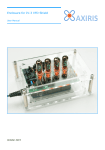
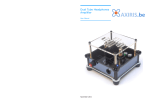
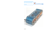
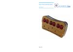
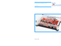
Enclosure for Hackberry A10
User Manual
February 2014
Bill of Materials
Assembly Instructions
9
10 11 12 13 14 15 16
1. Remove the protective films from the acrylic panels.
2. Stick the screws (13) through the holes of the bottom panel (2) and place the panel
on a horizontal surface. Be sure the countersunk holes in the corners are facing
downwards.
3. Slide a 3 mm spacer (15) over each of the four protruding screw threads and fit the
Hackberry on top. Make sure the FEL button is aligned with the corresponding hole in
the bottom panel.
1
7
4. Slide a washer (14) over each of the four screw threads.
8
5. Fit a nut (12) loosely on each of the four screw threads. Be sure you can still move
the Hackberry up and down.
6
6. Lift the front side of the Hackberry carefully just enough to be able to install the front
side panel (3).
7. Fasten the clip (7) with the antenna inserted onto the backside panel (4) using the
nylon screw (8). DO NOT exert too much force when tightening the screw!
5
8. Mount the three other side panels (4, 5, 6) to the Hackberry.
9. Wrap a rubber band around all four side panels to hold them together.
2
10.Tighten all four nuts (12).
4
11.Mount the top panel (1) on top of the assembly. Make sure the hole near the right
side of the top panel is positioned above the push button on the Hackberry.
12.Remove the rubber band.
3
13.Insert a 25 mm spacer (9) in each corner between the top panel and the bottom
panel. Drive an M3 hex. screw (11) at the top and an M3 countersunk hex. screw (10)
at the bottom. DO NOT exert too much force when tightening the screws!
14.Stick a rubber foot (16) on each M3 countersunk hex. screw on the bottom panel.
#
Description
#
Description
1
Transparent acrylic top panel
9
25 mm spacers
2
Black acrylic bottom panel
3
Transparent acrylic front side panel
11
M3 hex. screws top side
4
Transparent acrylic back side panel
12
M2 steel nuts
5
Opaque acrylic right side panel
13
M2 screws
6
Opaque acrylic left side panel
14
M2 nylon washers
7
Nylon clip for holding the antenna
15
3 mm spacers
8
M4 nylon screw for fastening the clip
16
Rubber feet
10
ADDITIONAL ASSEMBLY INSTRUCTIONS
M3 countersunk hex. screws bottom side
Please be gentle with the acrylic panels. If a panel refuses to assume the correct
position, avoid exerting more force on the panel. Instead go back a number of steps
and try assembling the case again.
Be careful not to snap off any corner of the top panel or bottom panel during
assembly. Don't lift a panel by the corners. Don't push a corner to fit a panel. Don't
exert too much force when tightening the screws.
Contact Information
Official website: http://www.axiris.eu/
2
User Manual
User Manual
3