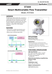
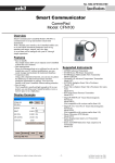
Download Communicating with HoneywellTM ST3000/STT3000 Smart
Transcript
Last Updated: 10-March-2009 TB-960704B Technical Bulletin, Communicating with TM Honeywell ST3000/STT3000 Smart Transmitters OMNI FLOW COMPUTERS, INC. 12620 West Airport Boulevard, Suite 100 Sugar Land, Texas 77478 United States of America Phone-281.240.6161 Fax: 281.240.6162 www.omniflow.com 52-0003-0001/Rev B Page 1 of 7 TB-960704B Communicating with HoneywellTM ST3000/STT3000 Smart Transmitters NOTE: User Manual Reference - This Technical Bulletin complements the information contained in the User Manual and is applicable to all firmware revisions. This Technical Bulletin was previously published as an appendix to user manuals of firmware revisions Version .70 and earlier. Communication with HoneywellTM ST3000/STT3000 Smart Transmitters – This feature allows you to communicate with Honeywell Smart Temperature and Pressure Transmitters, via OMNI’s H type Process I/O Combo Module and using Honeywell’s DE Protocol. Table of Contents Scope ............................................................................................................................................3 Abstract .........................................................................................................................................3 Digitally Enhanced (DE) Protocol Overview ..................................................................................3 Transmitter Database....................................................................................................................3 Using the Honeywell Handheld Communicator ..........................................................................3 Combo Module LED Status Indicators ..........................................................................................4 Switching Between Analog and Digital Mode................................................................................4 Auto Mode .................................................................................................................................4 Manual Operation......................................................................................................................4 Viewing the Status of the Honeywell Transmitter from the OMNI Front Panel...........................4 52-0003-0001/Rev B Page 2 of 7 TB-960704B Communicating with HoneywellTM ST3000/STT3000 Smart Transmitters Scope All firmware revisions of OMNI 6000/OMNI 3000 Flow Computers have the feature of communicating with Honeywell ST3000 Smart Transmitters. This feature uses Honeywell’s Digitally Enhanced (DE) Protocol and requires that an H Combo I/O Module be installed in your flow computer. Abstract Using 'H' Combo I/O Modules, the OMNI Flow Computer can communicate with Honeywell Smart Temperature and Pressure Transmitters using Honeywell’s DE Protocol. Up to four (4) transmitters can be connected to each 'H' Type Combo Module, with loop power being provided by the combo module. Digitally Enhanced (DE) Protocol Overview Digital data is transmitted serially between the flow computer and Honeywell Smart Transmitters by modulating the current in the two wire loop connecting the devices. Power for the transmitter is also taken from this current loop. Data is transmitted at 218.47 bits per second with a digital '0' = 20 mA and a digital '1’ = 4 mA. In normal operation, the Honeywell transmitter operates in the ‘6-byte Broadcast Mode'. In this mode, the transmitter transmits the following data to the flow computer every 366 msec: Byte #1 Byte #2-#4 Byte #5 Byte #6 Status Flags Process Variables % Span Value (3-byte floating point) Database ID (indicates where in the transmitter’s database Byte #6 below belongs) Database Data Value Transmitter Database By using the data contained in Bytes #5 and #6, the flow computer builds and maintains an exact copy of the smart transmitters configuration database. A transmitter database varies in size from about 90 bytes for a pressure transmitter to 120 bytes for a temperature transmitter. It takes between 30 and 45 seconds to completely build a copy of the transmitter database within the flow computer. The transmitter database is continuously compared against the flow computer configuration settings for that transmitter. The flow computer automatically corrects any differences between the databases by writing the correct configuration data to the transmitter. Using the Honeywell Handheld Communicator The flow computer is responsible for configuring entries within the transmitter. 1) Lower Range Value (LRV) or Zero 2) Transmitter Span or Upper Range Limit (URL) 3) Damping Factor 4) Tag Name Any changes made to one (1), two (2) and three (3) using the handheld communicator will be overwritten by the flow computer. In the digital mode it is not necessary to calibrate the transmitter output using the handheld communicator. The digital signal can be calibrated using the normal OMNI analog input method described in Chapter 8 of Volume 1. 52-0003-0001/Rev B Page 3 of 7 TB-960704B Communicating with HoneywellTM ST3000/STT3000 Smart Transmitters Combo Module LED Status Indicators Each I/O channel of the 'H' Combo module has a set of two (2) LED indicators, one (1) green and one (1) red. The green LED shows all communication activity taking place on the channel (flow computer, transmitter and handheld communicator if connected). The Red LED lights only when the flow computer is transmitting data to the transmitter. Normal digital operation is indicated by a regular pulsation of the green LED (about 3 per second). The red LED will be seen to blink whenever a configuration change is made in the flow computer which affects that particular transmitter. Switching Between Analog and Digital Mode Auto Mode Connecting an analog mode Honeywell smart transmitter to the computer will cause the flow computer to automatically switch the transmitter to the digital DE mode, sending out a communication request to the Honeywell transmitter. A switch over to the digital mode by the transmitter will cause the green LED on the H combo module to pulse steadily indicating that communications have been established. Manual Operation For manual operation, do the following: Disable communications between the Honeywell transmitter and the flow computer by deleting all I/O point assignments within the flow computer to that I/O point. Using the Honeywell SFC, SCT or any Honeywell handheld communicator, press [Shift] [A/D] and wait till the handheld displays 'Change to Analog?' Answer (Yes) by pressing [Enter]. ‘SFC Working’ will be displayed. The 'H' Combo module’s green LED on that channel will stop pulsing. Re-enter the I/O point to cause the OMNI to send the communication request command to the Honeywell and after three (3) commands send, the green LED on the Honeywell module will pulse at a steady 3Hz rate. Viewing the Status of the Honeywell Transmitter from the OMNI Front Panel To verify the data being received from the smart transmitter, press [Input], [Status] and [Enter] from the front panel. The following displays: H1‐2 Transmitter PV% ‐ 25.00 Status IDLE LRV .0 SPAN 150.0 Damp Sec. .00 Conformity bit 0 SW Revision 2.1 Serial # xxxxxxxx Transmitter Type GP URL 3000 ID/TAG PT202 SV .00 H1-2 Transmitter: Indicates the Honeywell Combo Module (H1) and the channel number on that module (Channel 2 in this case). PV%: Process variable value in percentage of the transmitter’s span. A -25.00 displayed on the OMNI could mean that the transmitter is not communicating (refer to Status). 52-0003-0001/Rev B Page 4 of 7 TB-960704B Status: Communicating with HoneywellTM ST3000/STT3000 Smart Transmitters There are five status states. 1) OK: 2) 3) 4) 5) Communications between the flow computer and smart Honeywell transmitter are OK. The database within the transmitter matches the flow computer. Idle: This flow computer I/O point has been assigned to a Honeywell transmitter but is not receiving data from the transmitter. Possible cause is a wiring problem such as reversal of wiring. If you observe the status LEDs you will note that the flow computer attempts to establish communications by sending a wake-up command every ten (10) seconds or so. Bad PV: Communications between the flow computer and smart Honeywell transmitter are OK but the transmitter has determined that a critical error has occurred within the transmitter meaning the value of the process variable cannot be trusted. The flow computer will set the transducer failure alarm and follow the fail code strategy selected by the user for this transducer. DB Error: Communications between the flow computer and smart Honeywell transmitter are OK but the flow Computer has determined that the database within the flow computer does not agree with the database within the transmitter. If you observe the status LEDs you will note that the flow computer attempts to correct the transmitters database by writing the correct data to the transmitter once every 30-45 seconds or so. 4 Byte: The transmitter is operating in the 4-Byte Broadcast Mode. Because the flow computer will not tolerate this mode of operation, this status display should only be displayed momentarily as the flow computer will automatically switch the transmitter into the 6-Byte Broadcast Mode. LRV: Lower Range Value of the transmitter in engineering units. Engineering units are degrees Celsius for temperature transmitters, inches of water for differential pressure transmitters, and pounds per square inch for pressure transmitters. Span: The Span of the transmitter in engineering units (the Span is the difference between the lower and upper ranges of the transmitter). Engineering units are degrees Celsius for temperature transmitters, inches of water for differential pressure transmitters, and pounds per square inch for pressure transmitters. The flow computer will display ‘DB Error’ if the user tries to enter a span of 0% or a span which would exceed the transmitter’s upper range limit' (URL). Damp Seconds: Damping Time of the transmitter output in seconds. Conformity Bit: Meaningful only with differential pressure transmitters. Conformity Bit 0 = linear output; Conformity Bit 1 = square root output. This bit should always be 0 for smart temperature transmitters. Software Revision: Current Software installed within the smart device. Serial #: Serial Number of the smart transmitter. Transmitter Type: Valid transmitter types are: TT DP GP = Temperature Transmitter = Differential Pressure Transmitter = Gauge Pressure Transmitter URL: Upper Range Limit of the transmitter in engineering units. The transmitter will not accept configuration entries which exceed this value. ID/TAG: ASCII string used to identify the transmitter. 52-0003-0001/Rev B Page 5 of 7 TB-960704B SV: Communicating with HoneywellTM ST3000/STT3000 Smart Transmitters Secondary Process Variable Value expressed in C. This represents sensor temperature for pressure transmitters, and junction temperature for temperature transmitters. The flow computer may or may not have a value in this field, depending upon whether the SV is included in the part of the transmitter’s database which is sent to the OMNI. 52-0003-0001/Rev B Page 6 of 7 TB-960704B Communicating with HoneywellTM ST3000/STT3000 Smart Transmitters DOCUMENT REVISION HISTORY DOCUMENT INITIAL RELEASE DATE......................................................03-May-2003 REVISION A B DATE 03-May-2003 10-March-2009 PURPOSE / CHANGE REQUEST Maintained on the Web - Initial release DCR 090079 52-0003-0001/Rev B Page 7 of 7


