1
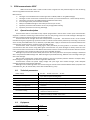
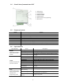
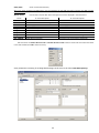
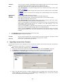
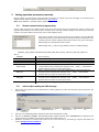
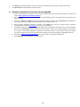
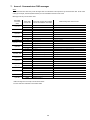
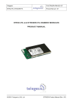
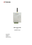
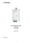
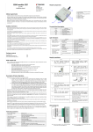
GSM communicator G10F (v.1.62) Setup Manual Draugystes g. 17, LT-51229 Kaunas E-mail: [email protected] www.trikdis.lt 2 Purpose of the document This document introduces the features of GSM communicator G10F, describes its operation, parameter setting procedure and usage peculiarities. Contents 1. GSM communicator G10F 1.1. Operation description 1.2. Technical parameters 1.3. Equipment 1.4. Overall view of communicator G10F 1.5. Purpose of contacts 1.6. Light indication 2. Communicator setup 2.1. Setup procedures 2.2. Connection diagrams 3. Setting operation parameters 4. Upgrading communicator firmware 5. Setting operation parameters remotely 5.1. Remote communicator programming 5.2. Actions after sending an SMS message 6. Remote communicator firmware version upgrade 7. Annex 1. Communicator messages 8. Safety requirements 9. Warranty and limitation of liability 3 3 3 3 4 4 4 5 5 6 6 11 12 12 12 13 14 15 15 3 1. GSM communicator G10F GSM communicator G10F is used to send fire alarm signals from the protected object to the monitoring station using GSM communication channels. Main features: messages are transmitted to the monitoring station via GPRS, DTMF or using SMS messages; messages are sent via the main communication channel or, if communication fails – via the backup channel; information may be sent using SMS messages if GPRS connection fails; sent messages match protocol Contact ID codes; ability to send SMS messages to the mobile phones of up to 4 users; operation parameters and firmware version may be upgraded remotely; operation parameters are set using G10config. 1.1. Operation description Communicator G10F is connected to relay outputs programmed in the fire alarm control panel. Communicator supports a continuous monitoring of their statuses and once they change, forms and sends messages. Messages are sent to the monitoring station and/or to the user mobile phones. . Communicator sends messages about the events/restores in input IN1 ... IN3 external circuits to the contacts indicated during the programming. Input IN4 is used to indicate communication problems by connecting it to the fire alarm control panel INIM Smart Line (or identical). Input IN4 power supply is discontinued if connection between the communicator and the receiver is lost for longer than 300 seconds. Communicator sends connection testing signals TEST periodically and may perform a continuous control of communication with the receiver using PING signals. Communicator may send messages via backup channels if the main communication channel fails. If two GPRS communication channels are set and communication with the receiver is lost, information to the monitoring station may be sent using SMS messages. Messages may also be sent to the mobile phones of 4 users. Every fire alarm control panel message is attributed with a comprehensible SMS message text. SMS messages may be divided among different users according to the type of the sent message. Status of the communicator output OUT2 changes in case of an operation problem. Statuses of outputs OUT1, OUT3 change if a message fails to be sent for longer than 300 seconds. Communicator controls the power supply voltage and upon larger than allowed changes, sends adequate messages and signals using the light indicators. Messages in the monitoring station are received using the receiver with installed software IPcom (computer with installed IPcom_Win, IP receiver RL10, server with installed IPcom_Linux). 1.2. Technical parameters Power supply Used current GSM modem frequencies Memory Input Input for fire alarm control panel indication management Output Parameters setting Workplace Measures 1.3. DC 20 V ... 36 VDC or AC 14 V ... 25 VAC 60 ... 100 mA (on standby), up to 500 mA (while sending data) 850 / 900 / 1800 / 1900 MHz up to 60 messages 3, input type EOL=10 kΩ 1, INIM Smart Line (or identical) to manage communication status indicators 3, OC type, commutate DC up to 50 V and current up to 100 mA using a USB port remote connection via IPcom temperature from -10C to +50C, relative humidity up to 80 % when +20C 65 x 79 x 25 mm Equipment Communicator G10F Adhesive mounting tape (10 cm) Resistor 10 kΩ 1 pc. 1 pc. 3 pc. 4 1.4. Overall view of communicator G10F 1. 2. 3. 4. 5. 6. 7. 1.5. Purpose of contacts Contact +E COM IN1 IN2 IN3 IN4 OUT1 OUT2 OUT3 1.6. GSM antenna Terminal block Indicator Network Indicator Trouble Indicator Power USB connection for programming SIM card slot Purpose +24 V power supply terminal General terminal 1st input terminal (type EOL=10 kΩ) 2nd input terminal (type EOL=10 kΩ) 3rd input terminal (type EOL=10 kΩ) 4th input terminal to connect to +Dialer terminal in the fire alarm control panel 1st output terminal (OC type), no connection 2nd output terminal (OC type), communicator operation problems 3rd output terminal (OC type), no connection (operation opposite to OUT1) Light indication Light indication Network denotes the connection status with the GSM network Trouble denotes communicator operation problems Status Green light Yellow light Green flashing Description Communicator is connected to a GSM network A message is being sent Connecting to a GSM network The amount of yellow flashes denotes GSM connection strength No operation problems Low power supply voltage (below 23 V) SIM card problem (no or wrong SIM card) SIM card PIN code problem (incorrect PIN code) Programming problem Registration to GSM network problem Registration to GPRS network problem No communication with the receiver for more than 300 seconds At least one of the input circuits is broken Power supply and microprocessor are in operation Yellow flashing OFF 1 red flash 2 red flashes 3 red flashes 4 red flashes 5 red flashes 6 red flashes 7 red flashes 8 red flashes Power denotes power supply status, microprocessor operation and programming mode. Green flashing Insufficient power supply voltage (below 19 V), microprocessor is in operation Yellow flashing Green and yellow flashing Programming mode in turns 5 2. Communicator setup 2.1. Setup procedures Action 1. Set communicator parameters. operation Notes Use information laid out in section Setting operation parameters. For example, to receive all the messages via one channel, e.g. via GPRS, it is enough to: see G10config Main window. Enter communicator (object) identification number into the field Object ID amd PING signal and Test message sending periods into fields GPRS PING time and Test time; see G10config GPRS reporting window. Select the GPRS transmission channel in the list Primary reporting, enter static IP address of the monitoring station and the port number in the fields Server IP1 address or Domain and Port, enter the access point name (APN) of the GPRS network in which the SIM card that is inserted into the communicator operates in the field APN and a six-digit encryption password that must match the IP receiver message decryption password in the field Encryption key. Note: Do not delete DNS factory values. 2. Insert an active SIM card. Refer to your mobile network operator with regard to the SIM card. It is not recommended to use pre-paid SIM cards. 3. Attach the communicator into the control panel casing using M3x6 screws, adhesive mounting tape or plastic holder PH. Position and measures of the holes to be drilled in the casing for mounting the communicator and the antenna: Positions and measures of the holder PH and holes for mounting: 4. Screw the GSM antenna. 5. Connect communicator to the fire alarm control panel according to the diagram. See section Connection diagrams. 6. Turn on the power supply. 7. Evaluate whether the strength of the GSM connection is sufficient by looking at the light indicators. Sufficient level is level 5 (5 yellow flashes by light indicator Network). Use a different type antenna if the GSM connection level is insufficient. 8. Check whether communicator is sending messages according to the parameters set during the configuration. A message must be sent and received at the set IP address. Check whether all SMS messages are received if messages are sent to the mobile phone. 6 2.2. Connection diagrams Diagram for connecting communicator G10F to the fire alarm control panel Note: Input IN4 can only be connected to the fire alarm control panel terminal +Dialer. Input IN4 power supply voltage will be disconnected if communication between the monitoring station and the message receiver does not work for more than 300 seconds. For this reason, control panel (e.g. Smart Line or identical) will indicate a problem – connection with the monitoring station is lost. Input type EOL, voltage at the end of the line (EOL = 10kΩ) An event is formed once external circuit status changes: short-circuit in the external input circuit – Event; voltage is restored to 10 kΩ after short-circuit – Event restore; external input circuit is broken – Sensor Tamper; voltage is restored to 10 kΩ after being broken – Sensor Tamper Restore. 3. Setting operation parameters Operation parameters of communicator G10F are set using software G10config. Software may be found on www.trikdis.lt . 1. Connect the communicator G10F to a computer using a USB cable. Note: A USB driver must be installed on the computer. A USB driver installation window Found New Hardware Wizard should appear on OS MS Windows during the first cable connection between the communicator and the computer. Download OS MS Windows USB driver installation file USB_COM.inf from the website www.trikdis.lt. Select Yes, this time only when prompted and click Next. A new window Please choose your search and installation options will open. Click Browse and select the location where USB_COM.inf is saved. To finish the USB driver installation follow remaining installation wizard commands. 2. 3. Run G10config. Select Connect in the menu. 7 Settings that may be edited upon connecting with User password Settings for connecting using a USB Enter wireless programming phone numbers Select the USB port to which the communicator is connected in the list Port. Note: the particular USB port to which the communicator is connected appears only when the two are connected. Select the desired working language in the list Language. 4. Click Connect [F2/F8]. Indicator Power should flash green and yellow in turns when communicator G10F is connected to a computer. Connection status Connected should be displayed in the G10config status bar alongside the information about the connected communicator: Dev: G10F Communicator type SN: 000002 Communicator serial number Ver: 1.62 Communicator firmware version 5. Click Read [F7]. Enter the access code (default – 1234) when prompted and click OK. Click Remember if you want the software to remember your access code. The prompt window will not appear next time. Tick Save access code for software to remember the password and not require for it next time. Tick Read after connection for the software to read the data automatically once connected. 8 Click Restore [F11] to restore to factory settings. When prompted, click Yes. Select Main in the menu and set desired parameters: Object ID Hex SIM card PIN code User code Field to enter the four-digit identification number; Tick if hexadecimal numbers will be used while entering the object ID; Field for SIM card PIN code. Leave the field empty if PIN code request is disabled; Field to enter the user code. Only those operation parameters that are allowed to be edited by the administrator can be edited when logging in with the user code; Admin code Field to enter the admin code. All operation parameters can be edited when logging in with the admin code. Also, possibilities for editing the operation parameters for those logging in with the user code may be limited; Panel type Select the desired input operation mode from the list. GPRS PING time Communicator will send GPRS to receiver communication test signals PING in a specified time period; CSD PING time Communicator will send CSD to receiver communication test signals PING in a time period; SMS PING time Communicator will send SMS to receiver communication test signals PING in a time period; Test time Communicator will send communication testing messages TEST to the monitoring station in a specified time period; Return to primary after Used if both communication channels to the monitoring station are selected – main and backup. Enter the time interval value after which communicator will try to restore the communication via the main channel (when using the backup communication channel). Backup reporting after ... attempts Used if both communication channels to the monitoring station are selected – main and backup. Enter the number of times communicator will try to send a message via the main communication channel and upon failure will send messages using the backup communication channel. 9 Enter parameters for communication with the monitoring station in GPRS reporting: Primary reporting Select the main communication channel via which communicator will send messages to the monitoring station: Set GPRS and enter the IP address and the port number of the monitoring station in the fields Server IP1 address or Domain and Port. Set DATA and enter the PSTN receiver phone number in the field Tel.1 in order to send Contact ID messages in DTMF tones. Phone number is entered with the international country code, but without the + sign. Set SMS and enter the SMS receiver phone number to which SMS messages containing Contact ID event codes will be sent in the field Tel.1. Phone number is entered with the international country code, but without the + sign; Backup reporting Select the backup communication channel via which communicator will send messages if communication via the main one is lost: Set GPRS and enter the second IP address and the port number of the monitoring station in the fields Server IP1 address or Domain and Port. Set DATA and enter the PSTN receiver phone number in the field Tel. 2 in order to send Contact ID messages in DTMF tones. Phone number is entered with the international country code, but without the + sign. Set SMS and enter the SMS receiver phone number to which SMS messages containing Contact ID event codes will be sent in the field Tel.2. Phone number is entered with the international country code, but without the + sign; Tel. 2 Enter the phone number of the monitoring station SMS receiver to which SMS messages will be sent if communication via main and backup channels is lost. This option is only allowed when main and backup communication channels are set to GPRS. Phone number is entered with the international country code, but without the + sign; Protocol Encryption key Select the message encryption protocol from the list; Field to enter the six-digit encryption password. Password must match the decryption password entered in the receiver software IPcom; IP addresses, port and phone number, encryption protocol and key, other parameters may only be submitted by the station manager APN User Password GSM network operator access point name; Login for connection to the GSM network; Password for connection to the GSM network; 10 DNS1, DNS2 Server names of the domains; APN, user name, password and DNS values must be submitted by the GSM connection operator the SIM card was purchased from. Module events Events TIME TEST POWER IN1_EVENT IN2_EVENT IN3_EVENT IN4_EVENT IN1_TAMPER IN2_TAMPER IN3_TAMPER Communicator events after which messages are sent are displayed in the table below. “E“ event description Internal clock of the communicator set Periodic communicator TEST message Power supply lower than 19 V Short-circuit in input IN1 circuit Short-circuit in input IN2 circuit Short-circuit in input IN3 circuit Short-circuit in input IN4 circuit Input IN1 circuit broken Input IN2 circuit broken Input IN3 circuit broken “R“ event description Internal clock of the communicator not set Power supply restored to 25 V Input IN1 circuit after the short-circuit restored Input IN2 circuit after the short-circuit restored Input IN3 circuit after the short-circuit restored Input IN4 circuit after the short-circuit restored Input IN1 circuit restored after being broke Input IN2 circuit restored after being broke Input IN3 circuit restored after being broke Left-click twice on Contact ID event code or Contact ID restore code to edit an event code and enter new values in the new window (click OK to check if correct). Enter parameters necessary for sending SMS messages to the users in the menu Text SMS reporting: 11 Telephone Name SMS encoding Object ID Send SMS 6. 7. Enter user phone numbers T1, T2, T3, T4 to which SMS messages will be sent. Phone numbers are entered with the international country code, but without the + sign; Select which users will be sent messages after some type of an event occurs: Select Alarm/Restore to send SMS messages about zone violations/restorations (event codes E/R1XX , see Annex 1); Select Troubles to send SMS messages about system operation problems (event codes E/R3XX, see Annex 1); Select Tests to send communication test messages Test via SMS messages (event codes E6XX. See Annex 1). Select the desired SMS encoding from the list. Enter the object name which will be included into the SMS message text. Select which messages listed in the table Name will be sent to users via SMS messages: Select All to send messages about all events; Select Only described to send messages about events that are listed in tables Users, Zones, Partitions. These tables should only be used in exceptional cases. Entries in the table Users are linked with the user codes that are used to activate/deactivate the alarm system. Name of the user will be included in the SMS message, if the user activates/deactivates the alarm system; Entries in the table Zones are linked with the protected zone events. Zone name specified in the table will be included in the SMS message, when zone is violated/restored. Entries in the table Partitions are linked with the partitions of the security system into several independently protected areas. Area name indicated in the table will be included in the SMS message; Click Save [F6] to move entered values to the communicator G10F. Click Disconnect [F8] and unplug the USB cable. Save [F5] Open [F3] Click to save the entered values on the computer. A file with an extension .gst will be created and may be use in the future as a template to configure other modules. Click to open a saved file with .gst extension. 4. Upgrading communicator firmware Communicator firmware may be upgraded once the manufacturer updates communicator G10F with new operation features: 1. Download the newest G10F_vx.xx.prg file from www.trikdis.lt. Note. Firmware update files available only for registered users. 2. Connect the communicator G10F to the computer, open G10config and select Firmware in the menu. 3. Click Browse and select file G10F_vx.xx.prg saved on the computer in the field Open firmware file. 4. Click Start [F9]. Click Disconnect [F8] once the progress bar fills up. Disconnect the USB cable. 5. Plug in the USB cable back again. Firmware upgrade process lasts between 60 to 90 seconds. Wait until indicator Data stops flashing green and click Connect [F2] and Read [F7]. New communicator firmware version will be displayed in the G10config status bar. 12 5. Setting operation parameters remotely Remote setting of communicator G10F operation parameters is possible only when messages are received by the software IPcom. Software IPcom may be found on www.trikdis.lt . Note. IPcom Software is available only for registered users. 5.1. Remote communicator programming Send an SMS message to the GSM number of the SIM card inserted into the communicator G1OF in order to set operation parameters of the communicator remotely. Upon receiving an SMS message, the communicator G10F will initiate a continuous GPRS communication session with software IPcom. If the phone number of the authorised person was entered in the field Wireless programming phones previously during the setting of operation parameters, the communicator will initiate a GPRS communication session only upon receiving an SMS message from that specific phone number. SMS message text (“_“refers to a gap between words in an SMS message): CONNECT_9874_SERVER=100.100.100.100_PORT=1000_APN=supplier_USR=user_PSW=psw_ENCR=enc where: CONNECT 9874 SERVER=100.100.100.100 PORT=1000 APN=supplier USR=user PSW=psw ENCR=enc 5.2. start command; Enter the four-digit access code (default - 1234); SERVER= + enter the IP address of the computer with installed software IPcom; PORT= + enter the serial port number of the program IPcom; APN= + enter the access point name (APN) of the GPRS network in which the SIM card inserted into the communicator operates. Enter ..._APN=_... if the network provider does not require an access point name; USR= + enter the login user name of the GPRS network in which the SIM card inserted into the communicator operates. Enter ..._USR=_... if the network provider does not require an access point name; PSW= + enter the login password of the GPRS network in which the SIM card inserted into the communicator operates. Enter ..._PSW=_... if the network provider does not require an access point name; ENCR= + enter the six-digit message decryption password (default – 123456). Actions after sending an SMS message 1. Open IPcom and right-click on the identification number [Object ID] of the communicator whose parameters you wish to modify. 2. 3. Left-click on the G10config button appearing next to the identification number. Left-click on Connect and Read in the G10config taskbar. GPRS connection status Connected will be displayed in the program status bar if GPRS communication session with module G10F is on. Operation parameters of communicator G10F are set in the same way as connecting it using the USB cable (see section Setting operation parameters). 4. 13 5. 6. Click Write once desired parameter values are entered so that they are not moved to communicator G10F. Click Disconnect to end the GPRS connection session. 6. Remote communicator firmware version upgrade 1. 2. Send a SMS message to the GSM number of the SIM card inserted into communicator G10F (For details see section Setting operation parameters remotely). Open IPcom and right-click on the identification number [Object ID] of the communicator whose firmware you wish to upgrade. 3. Left-click on Connect and Read in the G10config taskbar. GPRS connection status Connected will be displayed in the program status bar if GPRS communication session with module G10F is on. 4. Select program G10config catalogue Firmware. Click Browse and select file G10F_vx.xx.prg previously downloaded from website www.trikdis.lt and saved on the computer. 5. Click Start to begin the upgrade process whose progress will be displayed in the progress bar. Once the progress bar fills up press Disconnect. Module will disconnect from receiver and will start firmware upgrade, it may take up to 5 minutes. Then firmware upgrade is finished the module will reconnect to the receiver and will be available for remote configuration. New communicator G10F firmware version bill be displayed in G10config status bar. 6. Read section Setting operation parameters if you wish to view or edit operation parameters. 7. Click Disconnect to end the GPRS connection session. 14 7. Annex 1. Communicator G10F messages Note: Communicator G10F may send messages that are indicated in the operation of communicator G10. Some event codes (for example, activation/deactivation) are not available and must not be used! Messages sent by communicator G10 Recorded event CID code E/R 100 E/R 110, 115 E/E 110 E/R 120 E 121 E/R 130 … 149 E/R 144 E/R 301 E/R 302, 309 E/R 321 E/R 351 E/R 400, 401, 406, 451 E/R 408 E/R 409 E 602 E/R 700 Event code sent to CSP E 100 R 100 E 110 R 100 E 110 R 110 E 120 R 120 E 121 E 130 R 130 E 144 R 144 E 301 R 301 E 302 R 302 E 321 R 321 E 351 R 351 E 401 R 401 E 408 R 408 E 409 R 409 E 602 E 700 R700 Text in the Contact ID standard SIA DC-05-1999.09 code table SMS message text sent to a user Medical Alarm MEDICAL PANIC ALARM Fire Alarm FIRE PANIC ALARM Fire Alarm FIRE PANIC ALARM* Panic Alarm PANIC ALARM Duress Alarm Burglary Alarm Burglary Alarm restore Sensor Tamper Sensor Tamper restore AC Loss AC Loss restore Low System battery Low system Battery restore Bell 1 Bell 1 restore Telco 1 fault Telco 1 fault restore Open by user Close by user Quick DISARM Quick ARM Key switch zone Key switch restored Periodic test report Time set** Time isn‘t set** DURESS ALARM ALARM Alarm restore ALARM* Alarm Restore* AC Power failure on control panel AC Power failure restored on control panel Battery Power failure on control panel* Battery Power restored failure on control panel* Bell trouble on control panel Bell trouble restore on control panel Phone Line trouble on control panel Phone Line trouble restored on control panel OPEN by CLOSE by Quick DISARM Quick ARM Key switch zone Key switch restored Periodic Test* * SMS message text as sent by communicator G10F. ** Event codes are indicated in ECID codes table. 15 8. Safety requirements Be sure to familiarise yourself with this manual before using communicator G10F. Communicator may only be set up and maintained by trained specialists, who possess knowledge about operation of low voltage and signal transmission devices and their safety requirements. Communicator G10F must be set up in limited access areas and in safe distance from sensitive electronic equipment. Communicator is not resistant to mechanical effects, humidity and aggressive chemical environment. 9. Warranty and limitation of liabilities By purchasing the Product, the Buyer agrees that the Product is a security system element informing about the status of the system. Set up Product does not decrease the possibility of the robbery, fire, burglary or any other breach of the premises. TRIKDIS is not liable in cases of the robbery, fire and other breaches of the premises of the Buyer and/or the Product user and shall not reimburse the resulting property or non-pecuniary damages. By purchasing the product, the Buyer agrees that TRIKDIS sells a Product that satisfies the requirements of the Buyer. TRIKDIS does not guarantee that the Product will operate in the indicated way if the Product is not used in accordance to its purpose and not set up in accordance to the User manual. TRIKDIS is not liable for the Product operation malfunctions, if they have occurred due to the loss of the GSM/GPRS/Internet connection or due to a failure in the networks of the connection service provider. TRIKDIS does not influence and is not liable for the pricing and costs of the GSM/GPRS/Internet connection operator services. TRIKDIS is not liable for the interruption of GSM/GPRS/Internet connection services to the Product buyer and/or the Product user and the property and non-pecuniary damages incurred thereof. TRIKDIS is not liable for the interruption in the electricity supply to the Product buyer and/or the Product user and the property and non-pecuniary damages incurred thereof. TRIKDIS is not liable if the Product Buyer and/or the Product user has not updated their product firmware version on time. There may be some technical inaccuracies, grammatical and typographical errors in the product manual. TRIKDIS reserves the right to edit, add and/or change the information in the manual. 16