1
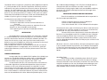
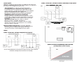
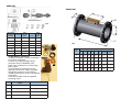
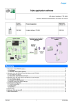
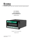
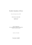
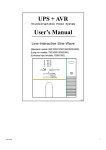
Rev 092012
USER MANUAL
MODEL CSLFC
ULTRASONIC FLOW TRANSMITTER
USER MANUAL
CLARK SONIC® MODEL CSLFC
The Model CSLFC is an ultrasonic transit time flow meter
designed to accurately and reliably report the flow of non-compressible fluids in pipe diameters ranging from 3 inch to 10 inches. It is a
2- wire device reporting flow in the industry standard 4-20 mA
protocol and a frequency/pulse output (when optionally ordered).
The meter introduces no pressure drop other than the pipe section
which provides the means to position the ultrasonic transducers and
to connect to the user’s piping system.
The small electronic board which implements all the functions to measure and report the flow is housed in the integral electronic enclosure and is sealed so as to protect the electronics from
the environment.
THEORY OF OPERATION
Two ultrasonic transducers are positioned and angled so as to
transmit and receive sound pulses that are launched at a flat reflection point located on the opposing side of the pipe. The flight time
of the sound pulse from the transmitting transducer to the receiving
transducer will be shortened if the pulse is launched in the direction
of flow and increased if launched opposite to the direction of flow.
By alternating the transmitting and receiving transducers, the difference in these transit times can be used to calculate the velocity of the
flow, which when multiplied by the area of the pipe, results in a
measure of volumetric flow rate which is then used to set the current
in the 4-20 ma loop proportional to the full scale value of the meter.
The path of this sonic pulse traverses the pipe diameter twice
and because of the generous spacing between transducers, the
volume of fluid which influences the time of flight of this pulse is
commensurate with the scale of the turbulence features in the flow.
Turbulence by its nature has chaotic velocity components and by
directing the sonic pulse through a volume comparable to the scale
of this chaos, the effect on the flight time on any single measurement are much reduced, resulting in measurements that show less
variation from the average. Stating it another way, a measure of the
Standard Deviation of a number of measurements will be reduced,
resulting in less uncertainty in the currently reported flow rate.
Clark Solutions
10 Brent Drive, Hudson, MA 01749
Tel. 978 / 568 3400 Fax 978 / 568 0060
www.clarksol.com
IMPLEMENTATION
The accuracy and precision of the determined flow rate is
ultimately determined by the accuracy and precision with which one
can measure the transit times.
The Model CSLFC incorporates a proprietary ASIC (Application Specific
IC ), which provides all the functions required to alternately transmit
and receive sonic pulses and measure the transit times to picosecond
accuracy. The ASIC implements the “Sing Around” method to launch
and receive pulses, each received pulse initiating the next transmitted
pulse. On any one measurement, a number of such cycles are used to
accumulate the individual transit times which are then divided by the
number of cycles to give an average of these measurements.
A microprocessor provides the following functions:
· Control and calibration of the ASIC.
· Calculations required to convert the measured times to
flow rate.
· Setting of the 4-20 mA loop current to represent flow rate.
· Response to User selectable switch settings.
· Fault reporting via an optically isolated open collector
output.
INSTALLATION
The Model CSLFC may be installed in any orientation, although
it is recommended that in horizontal pipe runs, an orientation which
positions the electrical enclosure vertically be avoided if possible. The
reason for this caution is that, with any transit time meter, erratic
behavior may result if bubbles are allowed to accumulate in the sound
path. A mounting orientation of the electrical
enclosure 90o from vertical is recommended. Install with a minimum
of five pipe diameters of straight pipe, free of transitions, upstream
and two pipe diameters, free of transitions, downstream of the flow
transmitter.
20 or 100 second period begins. This will allow the Model CSLFC to
always present the last valid flow rate while a new valid
measurement is being sought. Under such severe bubble conditions,
the meter will still give meaningful results but with longer times
between updates.
EXCEPTIONAL BEHAVIOR AND FAULT REPORTING
Three fault conditions can be detected and are reported via
the Fault output provided (FIG 2).
· Failure to perform necessary internal calibrations.
· Failure to make reliable measurements.
· Flow, which exceeds 125% of the selected Full Scale option.
The electronics must, upon initialization, be able to send and receive
sound pulses of a minimum strength. If it cannot, no measurements
can be made. This may come about for two reasons:
·
The most likely reason the electronics cannot be calibrated is
because of an interrupted sound. This would be the case if the pipe
was not completely filled or there is excessive air entrapped in the
fluid. Of least likelihood would be a system failure. Such a failure
may be a degraded transducer. Even less likely may be a failure in the
control electronics.
Whenever a there is a fault condition, the Opto Isolated Fault output
is set to conduct and the loop current is set to 4.0 Ma. The exception
is if the Fault occurs because of an over range condition. In this case
the Fault output is activated but the loop current is left in excess of
20 Ma.
DYNAMIC PERFORMANCE
During steady flow, the Model CSLFC updates the 4-20 Ma loop
current at a rate determined by the update time as selected by SW2
(Fig. 3). This update rate will either be every 10 seconds if “SLOW”
response has been set or every 2 seconds if the “FAST” is set.
Air entrained in the flow, will cause erroneous measurements
to be made. Algorithms have been developed that reject such measurements so that only valid measurements are retained. If a valid
measurement cannot be made within 20 consecutive attempts while in
the Fast mode, or within 100 consecutive attempts in the Slow mode,
then a Fault condition is activated. However, any time a valid measurement can be made before the 20 or 100 second period expires, a new
Watchdog Timer:
The software includes a Watchdog timer which will cause a
software reset should, for whatever reason, the code is not being
normally exercised for more than about 2 seconds. This reset will normally be transparent to the user. Should permanent damage to the
unit have occurred, the normal fault reporting cannot be invoked
and the Model CSLFC will have to be replaced.
USER SELECTABLE OPTIONS
There are three switches (FIG 3) accessible when the controller board
is exposed. Their functions are as follows:
· Reset.
o This is a small push button switch which when
activated resets the software as would occur if the
unit were power cycled.
· Full Scale
o This is a dip switch setting that allows the User to
select between two pre-programmed full scale values
for the pipe diameter currently used. See the
Specification section for detail.
· Response Time
This switch setting allows the User to select two
different update rates. In many applications, a longer
update rate is desired and acceptable. With this slow
er update rate, the Model CSLFC will average readings over a longer time, resulting, (in the case of
steady flow), a more constant reported flow rate. See
the Specification section for details.
o
In the case where the Model CSLFC is to be
used as a feedback transducer in a control
loop, a faster response time may be desirable.
o
Use:
If either the Full scale or Response Time switch has been
changed since the last Reset or power cycle, then the Model
CSLFC must be reset using the Reset switch or else power cycled.
CALIBRATION
As mentioned in the “Theory of Operation” and the “Implementation” sections, the Model CSLFC employs the Sing Around
method of determining transit times. This method results in a measurement of fluid velocity which is independent of the speed of sound
through the fluid and hence its dependence on temperature. This
speed of sound independence removes all need for field calibration.
However, to report volumetric flow rate, this velocity must be multiplied by the cross sectional area through which the velocity was
measured. This area is set by the internal pipe diameter, D. Any
uncertainty in D translates directly to an uncertainty in flow rate, Q.
Quantitatively,
Q(% error) = 200 * d/D, where d is the +/- tolerance of D.
As an example, a +/- .01 inch uncertainty in the nominal
diameter of a 2 inch pipe would result in a +/- 1 % error in reported
flow rate, Q.
At Clark Solutions each meter is calibrated against a traceable
standard meter and a constant set in software, which reflects this
actual diameter rather than the nominal diameter. This method of
calibration removes an otherwise indeterminate error.
The error resulting from the thermal expansion of the diameter over the specified temperature range would however result in the
flow rate being under reported by 0.1 %.
SPECIFICATIONS
GENERAL
Flow Range: Bi-directional, field selectable per “Standard Models”
table
Accuracy: ±0.75% of full scale
Operating Temperature: -40 to 190oF (-40 to 87.8oC))
Response Time: User selectable, 2 or 10 seconds
Viscosity Range: 0.2 to 150 cSt (0.2 to 150 mPas)
Liquid Density: 30.6 to74.9 lb/cu.ft. (490 to 1200 kg/m3)
Max. Working Pressure: 200 PSI (13.8 bars)
Pipe Sizes: 3”, 4”, 6”, 8”, 10”
Pipe Connections: ASME class 150 flange
Electrical Enclosure: Integral to Body casting with gasketed cover;
One 1/2” NPT conduit connection (plugged when model ordered
with metric threads) and one M16 x 1.5 connection (plugged
when model ordered with NPT threads)
Electrical Connections: Screw terminal connections on PC board
Enclosure Rating: NEMA 4 (IP 65)
Power Supply: 18 to 36 VDC
WETTED MATERIALS
Ultrasonic Transducers: ULTEM® Encapsulated
Seals: EPDM, Buna-N, Neoprene™, FKM, or other
Body Material: Schedule 40, epoxy coated, carbon steel pipe
OUTPUT
Analog: 2-wire, 4-20 mA output; Output is 4 mA from zero to min.
flow (see Standard Model table)
Loop Resistance: See FIG. 4
OUTPUT CONT’D
Additional outputs: A second output is available in the form of an
optically isolated NPN transistor. The second output is configured at
the factory. The configuration choices are:
2-WIRE, 4-20 MA LOOP, OPTIONAL ALARM OR DIRECTION OF FLOW OUTPUT
FIG 2
-Error Detection: An optically isolated sink output is
activated under certain detectable fault conditions, such
as transducer failure or overly noisy output due to flow
stream anomalies, as might be seen due to excessive bubble
entrainment.The optional Fault output is an
optically isolated NPN transistor capable of sinking up to
25 mA from a voltage source of no more than 48 VDC.
-Frequency: output is an optically isolated NPN
transistor capable of sinking up to 25 mA from a
voltage source of no more than 48 VDC.Frequency output
is from 240 to 1200 pulses/gallon depending on range (see
Standard Model table). Lower frequency can be provided
on request
-Direction of Flow: Optional output to indicate
direction of flow is available. Activation or
deactIvation of an optically isolated 25 mA sink output
indicates flow direction. Error detection is not available
when this option is ordered.
Optional Temperature Sensor: 3 wire RTD, 100 Ohm,
Platinum, Class A, IEC60751, built in to transducer shell for
monitoring process temperature; optional 4 or 8 pin
electrical connector recommended with this option
FIG 3
WIRING
2-WIRE, 4-20 MA LOOP, OPTIONAL FREQUENCY/PULSE OUTPUT
FIG 1
4-20 mA
The opto-isolated NPN transistor that generates the square wave pulse output is limited to
25 mA when conducting and to 48 volts when non-conducting
FIG 4
ONNECTORS
DIMENSIONS
4R/8R Receptacle
4C/8C Field Connector
FIG 5
4C
4R
8C
8R
Transmitter
8-pin
4-pin
8-Pin (8C) Connector 4-Pin (4C) Connector
Connection Connector
Connector
Terminal
Cable
Cable
+
1
Brown
1
Red
-
2
White/Brown
2
Black
C (Collector)
3
Green
3
White
E (Emmiter)
4
White/Green
4
Green
RTD Red
5
Orange
RTD Red
6
White/Blue
RTD White
7
Blue
4H Hirshmann Connector
1) GSP312 assembly is factory installed on
to the flow transmitter.
2) Insert wire cable through female
connector shell of GDM3012J and
fasten wire conductors to terminals per
below table.
3) Install GDM 3-7 gasket on to the
4-prong connector of GSP312 assembly.
4) Plug the connector to the GSP312
assembly and snap on shell in the desired
orientation.
5) Secure assembly with the supplied
mounting screw.
Terminal
1
4-20 mA and NPN Alarm
Output
4-20 mA and 100 Ohm RTD
(-) Vin Return, 4-20 mA
(-) Vin Return, 4-20 mA
(+) Vin Supply, 18-36 VDC, 4-20 mA (+) Vin Supply, 18-36 VDC, 4-20 mA
2
C Alarm (Collector)
RTD
3
E Alarm (Emmitter)
RTD
FIG 6
Dimensions (Inches)
Pipe
Size
A
B
C
D
E
F
3”
11.00
7.50
3.50
6.54
2.62
0.75
6.00
4
4”
13.00
9.00
4.00
6.54
2.62
0.75
7.50
8
6”
16.00 11.00 5.09
6.54
2.62
0.88
9.50
8
8”
18.00 13.50 6.11
6.54
2.62
0.88
11.75
8
10”
22.00 16.00 7.18
6.54
2.62
1.00
14.25
12
Bolt Circle Number of
Diameter
Holes
STANDARD MODELS
*Field Selectable
*Field Selectable
Full Scale Ranges
Full Scale Ranges
(GPM)
(LPM)
Min.
Max.
Min.
Max.
L
3.0
200
11.0
750
CSLFC3
3”
H
6.0
400
23.0
1500
L
4.5
300
17.0
1150
CSLFC4
4”
H
7.5
500
29.0
1900
L
9.0
600
35.0
2300
CSLFC6
6”
H
18.0
1200
68.0
4500
L
15.0
1000
57.0
3800
CSLFC8
8”
H
30.0
2000
114
7600
L
22.5
1500
86.0
5700
CSLFC10
10”
H
45.0
3000
165
11000
*F.S. ranges can be user specified to 125% of each stated high (H) range with no change to specifications and to 25% of each low (L) range with some
specification modification.
Pipe
Size
Model
Frequency Output Flow Constant Frequency Output Flow Constant
Option
(Gallons)
Option
(Liters)
Pulses/Gallon
Gal/Min=FC*Freq.
Pulses/Liter
L/Min=FC*Freq.
Model
Pipe
Size
CSLFC3
CSLFC4
3”
4”
72
60
0.833
1
18
15
3.33
4
CSLFC6
6”
30
2
6
10
CSLFC8
8”
15
4
3
20
CSLFC10
10”
12
5
3
20
ORDERING INFORMATION
ORDER NUMBER (ABCDE)
Example: CSLFC10GB-DP4H
*A
Model
CSLFC3
CSLFC4
CSLFC6
CSLFC8
CSLFC10
B
Units of Measure
G= Gallons Per Minute (U.S.)
L= Liters Per Minute
C
Transducer Seal
E= EPDM
B= Buna-N
N= Neoprene®
V= FKM
D
Options
NPN Transistor Output
Select One
-= Error Detection (Default)
F= Frequency Output
DF= Direction of flow output option
Other Options
R=100 OhmPlatinum RTD
DP=Display % F.S
DS=Display in Engineering Units- specify
*For non-listed ranges specify model followed by full span value
Example: CSLFC4-150G = 150 GPM at 20 mA or CSLFC4-750L=750LPM @ 20 mA
E
Transmitter
4H=Hirschmann 4-conductor Receptacle
& 1/2” NPTF Conduit Connector Set (Our
default/standard connector)
4R= 4-Pin Male Circular Receptacle
8R= 8-Pin Male Circular Receptacle
4C= 4-Pin Female Circular Connector
ULTEM® is a registered trademark of
The General Electric Company
Neoprene® is a registered trademark of DuPont Dow
CAUTION
Model CSLFC is for measurement of liquid flows only
Use only with liquids compatible with the materials of construction
Maximum Pressure: 200 PSIG
Maximum Temperature: 190oF