1
PDT 1100 Terminal
Programmer’s Guide
70-36099-01
Revision B — May 2001
2
Symbol Technologies, Inc. One Symbol Plaza, Holtsville N.Y. 11742-1300
PDT 1100 Terminal
Programmer’s Guide
70-36099-01
Revision B
May 2001
© 2001 by Symbol Technologies, Inc. All rights reserved.
No part of this publication may be reproduced or used in any form, or by any electrical or
mechanical means, without permission in writing from Symbol. This includes electronic or
mechanical means, such as photocopying, recording, or information storage and retrieval
systems. The material in this manual is subject to change without notice.
The software is provided strictly on an “as is” basis. All software, including firmware,
furnished to the user is on a licensed basis. Symbol grants to the user a non-transferable and
non-exclusive license to use each software or firmware program delivered hereunder (licensed
program). Except as noted below, such license may not be assigned, sublicensed, or otherwise
transferred by the user without prior written consent of Symbol. No right to copy a licensed
program in whole or in part is granted, except as permitted under copyright law. The user
shall not modify, merge, or incorporate any form or portion of a licensed program with other
program material, create a derivative work from a licensed program, or use a licensed
program in a network without written permission from Symbol. The user agrees to maintain
Symbol’s copyright notice on the licensed programs delivered hereunder, and to include the
same on any authorized copies it makes, in whole or in part. The user agrees not to
decompile, disassemble, decode, or reverse engineer any licensed program delivered to the
user or any portion thereof.
Symbol reserves the right to make changes to any software or product to improve reliability,
function, or design.
Symbol does not assume any product liability arising out of, or in connection with, the
application or use of any product, circuit, or application described herein.
No license is granted, either expressly or by implication, estoppel, or otherwise under any
Symbol Technologies, Inc., intellectual property rights. An implied license only exists for
equipment, circuits, and subsystems contained in Symbol products.
Symbol, Spectrum One, and Spectrum24 are registered trademarks of Symbol Technologies,
Inc. Other product names mentioned in this manual may be trademarks or registered
trademarks of their respective companies and are hereby acknowledged.
Symbol Technologies, Inc.
One Symbol Plaza
Holtsville, New York 11742-1300
http://www.symbol.com
ii
Contents
About This Guide
Notational Conventions . . . . . . . . . . . . . . . . . . . . . . . . . . . . . . . . . . . . . . . . . . . . . . . . . . . . . . . . . .xiv
Service Information . . . . . . . . . . . . . . . . . . . . . . . . . . . . . . . . . . . . . . . . . . . . . . . . . . . . . . . . . . . . . xv
Symbol Support Centers . . . . . . . . . . . . . . . . . . . . . . . . . . . . . . . . . . . . . . . . . . . . . . . . . . . . . . xv
Related Publications . . . . . . . . . . . . . . . . . . . . . . . . . . . . . . . . . . . . . . . . . . . . . . . . . . . . . . . . . . . . .xvi
Warranty . . . . . . . . . . . . . . . . . . . . . . . . . . . . . . . . . . . . . . . . . . . . . . . . . . . . . . . . . . . . . . . . . . . . .xvi
Warranty Coverage and Procedure . . . . . . . . . . . . . . . . . . . . . . . . . . . . . . . . . . . . . . . . . . . . . .xvi
General . . . . . . . . . . . . . . . . . . . . . . . . . . . . . . . . . . . . . . . . . . . . . . . . . . . . . . . . . . . . . . . . . . xvii
Chapter 1. Software Overview
Software Structure . . . . . . . . . . . . . . . . . . . . . . . . . . . . . . . . . . . . . . . . . . . . . . . . . . . . . . . . . . . . . 1-1
System Programs . . . . . . . . . . . . . . . . . . . . . . . . . . . . . . . . . . . . . . . . . . . . . . . . . . . . . . . . . . . 1-2
Application Programs . . . . . . . . . . . . . . . . . . . . . . . . . . . . . . . . . . . . . . . . . . . . . . . . . . . . . . . 1-3
Overview of BASIC 3.0 . . . . . . . . . . . . . . . . . . . . . . . . . . . . . . . . . . . . . . . . . . . . . . . . . . . . . . 1-3
BASIC 3.0. . . . . . . . . . . . . . . . . . . . . . . . . . . . . . . . . . . . . . . . . . . . . . . . . . . . . . . . . . . . . . . . . . . . 1-3
Features. . . . . . . . . . . . . . . . . . . . . . . . . . . . . . . . . . . . . . . . . . . . . . . . . . . . . . . . . . . . . . . . . . 1-3
Compilation and Program Execution . . . . . . . . . . . . . . . . . . . . . . . . . . . . . . . . . . . . . . . . . . . . . . . 1-4
Compiler and Interpreter. . . . . . . . . . . . . . . . . . . . . . . . . . . . . . . . . . . . . . . . . . . . . . . . . . . . . 1-4
Compiling and Interpreting Example. . . . . . . . . . . . . . . . . . . . . . . . . . . . . . . . . . . . . . . . . . . . 1-5
Chapter 2.
Development Environment and Procedures
Overview of Development Environment . . . . . . . . . . . . . . . . . . . . . . . . . . . . . . . . . . . . . . . . . . . . . 2-1
Required Hardware. . . . . . . . . . . . . . . . . . . . . . . . . . . . . . . . . . . . . . . . . . . . . . . . . . . . . . . . . 2-1
Required Software. . . . . . . . . . . . . . . . . . . . . . . . . . . . . . . . . . . . . . . . . . . . . . . . . . . . . . . . . . 2-2
Overview of Developing Procedures . . . . . . . . . . . . . . . . . . . . . . . . . . . . . . . . . . . . . . . . . . . . . . . . 2-2
Developing Procedures . . . . . . . . . . . . . . . . . . . . . . . . . . . . . . . . . . . . . . . . . . . . . . . . . . . . . . 2-2
Functions of the Compiler. . . . . . . . . . . . . . . . . . . . . . . . . . . . . . . . . . . . . . . . . . . . . . . . . . . . 2-3
Developing Procedure Flow. . . . . . . . . . . . . . . . . . . . . . . . . . . . . . . . . . . . . . . . . . . . . . . . . . . 2-3
iii
PDT 1100 Programmer’s Guide
Writing of a Source Program . . . . . . . . . . . . . . . . . . . . . . . . . . . . . . . . . . . . . . . . . . . . . . . . . . . . . .2-4
Writing a Source Program Using Editor . . . . . . . . . . . . . . . . . . . . . . . . . . . . . . . . . . . . . . . . . . 2-4
Rules for Writing a Source Program . . . . . . . . . . . . . . . . . . . . . . . . . . . . . . . . . . . . . . . . . . . . .2-4
Compiling in Windows . . . . . . . . . . . . . . . . . . . . . . . . . . . . . . . . . . . . . . . . . . . . . . . . . . . . . . . . . . 2-6
Setting up the Compiler . . . . . . . . . . . . . . . . . . . . . . . . . . . . . . . . . . . . . . . . . . . . . . . . . . . . . .2-6
Starting the Compiler . . . . . . . . . . . . . . . . . . . . . . . . . . . . . . . . . . . . . . . . . . . . . . . . . . . . . . . .2-7
Reading in the Initialization File . . . . . . . . . . . . . . . . . . . . . . . . . . . . . . . . . . . . . . . . . . . . . . . .2-7
Operating Procedure for the Compiler . . . . . . . . . . . . . . . . . . . . . . . . . . . . . . . . . . . . . . . . . . .2-8
Screen Shown During Execution of the Compiler . . . . . . . . . . . . . . . . . . . . . . . . . . . . . . . . . . 2-10
Output from the Compiler . . . . . . . . . . . . . . . . . . . . . . . . . . . . . . . . . . . . . . . . . . . . . . . . . . . 2-10
Generating a User Program. . . . . . . . . . . . . . . . . . . . . . . . . . . . . . . . . . . . . . . . . . . . . . . . . . . 2-12
Error Messages . . . . . . . . . . . . . . . . . . . . . . . . . . . . . . . . . . . . . . . . . . . . . . . . . . . . . . . . . . . .2-12
Compiling Options . . . . . . . . . . . . . . . . . . . . . . . . . . . . . . . . . . . . . . . . . . . . . . . . . . . . . . . . . 2-14
Designating the Work Drive and Directory. . . . . . . . . . . . . . . . . . . . . . . . . . . . . . . . . . . . . . . 2-15
Downloading . . . . . . . . . . . . . . . . . . . . . . . . . . . . . . . . . . . . . . . . . . . . . . . . . . . . . . . . . . . . . . . . . 2-16
Ir-Transfer Utility C & Ir-Transfer Utility E . . . . . . . . . . . . . . . . . . . . . . . . . . . . . . . . . . . . . .2-16
Setting up the PDT 1100 . . . . . . . . . . . . . . . . . . . . . . . . . . . . . . . . . . . . . . . . . . . . . . . . . . . . 2-16
Executing a User Program . . . . . . . . . . . . . . . . . . . . . . . . . . . . . . . . . . . . . . . . . . . . . . . . . . . . . . .2-17
Starting. . . . . . . . . . . . . . . . . . . . . . . . . . . . . . . . . . . . . . . . . . . . . . . . . . . . . . . . . . . . . . . . . . 2-17
Execution . . . . . . . . . . . . . . . . . . . . . . . . . . . . . . . . . . . . . . . . . . . . . . . . . . . . . . . . . . . . . . . . 2-17
Termination . . . . . . . . . . . . . . . . . . . . . . . . . . . . . . . . . . . . . . . . . . . . . . . . . . . . . . . . . . . . . . 2-17
Chapter 3. Program Structure
Statement Blocks . . . . . . . . . . . . . . . . . . . . . . . . . . . . . . . . . . . . . . . . . . . . . . . . . . . . . . . . . . . . . . . 3-1
Subroutines . . . . . . . . . . . . . . . . . . . . . . . . . . . . . . . . . . . . . . . . . . . . . . . . . . . . . . . . . . . . . . . 3-1
Error-/Event-Handling Routines . . . . . . . . . . . . . . . . . . . . . . . . . . . . . . . . . . . . . . . . . . . . . . . .3-1
Block-Format User-Defined Functions . . . . . . . . . . . . . . . . . . . . . . . . . . . . . . . . . . . . . . . . . . .3-1
Block-Structured Statements . . . . . . . . . . . . . . . . . . . . . . . . . . . . . . . . . . . . . . . . . . . . . . . . . . .3-2
Jumping Into/Out of Statement Blocks . . . . . . . . . . . . . . . . . . . . . . . . . . . . . . . . . . . . . . . . . . .3-3
Handling User Programs . . . . . . . . . . . . . . . . . . . . . . . . . . . . . . . . . . . . . . . . . . . . . . . . . . . . . . . . . 3-4
User Programs in the Memory . . . . . . . . . . . . . . . . . . . . . . . . . . . . . . . . . . . . . . . . . . . . . . . . .3-4
Program Chaining . . . . . . . . . . . . . . . . . . . . . . . . . . . . . . . . . . . . . . . . . . . . . . . . . . . . . . . . . . 3-4
Included Files . . . . . . . . . . . . . . . . . . . . . . . . . . . . . . . . . . . . . . . . . . . . . . . . . . . . . . . . . . . . . .3-5
Chapter 4. Basic Program Elements
Structure of a Program Line. . . . . . . . . . . . . . . . . . . . . . . . . . . . . . . . . . . . . . . . . . . . . . . . . . . . . . .4-1
Format of a Program Line . . . . . . . . . . . . . . . . . . . . . . . . . . . . . . . . . . . . . . . . . . . . . . . . . . . . 4-1
Program Line Length and Maximum Number of Lines . . . . . . . . . . . . . . . . . . . . . . . . . . . . . . 4-3
Usable Characters . . . . . . . . . . . . . . . . . . . . . . . . . . . . . . . . . . . . . . . . . . . . . . . . . . . . . . . . . . . . . .4-3
Special Symbols and Control Codes . . . . . . . . . . . . . . . . . . . . . . . . . . . . . . . . . . . . . . . . . . . . .4-4
Labels . . . . . . . . . . . . . . . . . . . . . . . . . . . . . . . . . . . . . . . . . . . . . . . . . . . . . . . . . . . . . . . . . . . . . . . 4-6
Rules for naming labels . . . . . . . . . . . . . . . . . . . . . . . . . . . . . . . . . . . . . . . . . . . . . . . . . . . . . .4-6
iv
Contents
Identifiers . . . . . . . . . . . . . . . . . . . . . . . . . . . . . . . . . . . . . . . . . . . . . . . . . . . . . . . . . . . . . . . . . . . . 4-7
Rules for Naming Identifiers . . . . . . . . . . . . . . . . . . . . . . . . . . . . . . . . . . . . . . . . . . . . . . . . . . 4-7
Reserved Words . . . . . . . . . . . . . . . . . . . . . . . . . . . . . . . . . . . . . . . . . . . . . . . . . . . . . . . . . . . . . . . 4-7
Chapter 5. Data Types
Constants . . . . . . . . . . . . . . . . . . . . . . . . . . . . . . . . . . . . . . . . . . . . . . . . . . . . . . . . . . . . . . . . . . . . 5-1
String Constants . . . . . . . . . . . . . . . . . . . . . . . . . . . . . . . . . . . . . . . . . . . . . . . . . . . . . . . . . . . 5-1
Numeric Constants . . . . . . . . . . . . . . . . . . . . . . . . . . . . . . . . . . . . . . . . . . . . . . . . . . . . . . . . . 5-1
Variables . . . . . . . . . . . . . . . . . . . . . . . . . . . . . . . . . . . . . . . . . . . . . . . . . . . . . . . . . . . . . . . . . . . . 5-3
Types of Variables According to Format . . . . . . . . . . . . . . . . . . . . . . . . . . . . . . . . . . . . . . . . . 5-3
Classification of Variables . . . . . . . . . . . . . . . . . . . . . . . . . . . . . . . . . . . . . . . . . . . . . . . . . . . . 5-5
User-defined Functions . . . . . . . . . . . . . . . . . . . . . . . . . . . . . . . . . . . . . . . . . . . . . . . . . . . . . . . . . . 5-6
Setting Character String Length of Character Functions . . . . . . . . . . . . . . . . . . . . . . . . . . . . . 5-6
Dummy Arguments and Real Arguments . . . . . . . . . . . . . . . . . . . . . . . . . . . . . . . . . . . . . . . . 5-7
Type Conversion . . . . . . . . . . . . . . . . . . . . . . . . . . . . . . . . . . . . . . . . . . . . . . . . . . . . . . . . . . . . . . 5-7
Type Conversion Examples . . . . . . . . . . . . . . . . . . . . . . . . . . . . . . . . . . . . . . . . . . . . . . . . . . . 5-8
Chapter 6. Expressions and Operators
Overview . . . . . . . . . . . . . . . . . . . . . . . . . . . . . . . . . . . . . . . . . . . . . . . . . . . . . . . . . . . . . . . . . . . . 6-1
Operator Precedence. . . . . . . . . . . . . . . . . . . . . . . . . . . . . . . . . . . . . . . . . . . . . . . . . . . . . . . . . . . . 6-1
Precedence. . . . . . . . . . . . . . . . . . . . . . . . . . . . . . . . . . . . . . . . . . . . . . . . . . . . . . . . . . . . . . . . 6-1
Operators . . . . . . . . . . . . . . . . . . . . . . . . . . . . . . . . . . . . . . . . . . . . . . . . . . . . . . . . . . . . . . . . . . . . 6-3
Arithmetic Operators . . . . . . . . . . . . . . . . . . . . . . . . . . . . . . . . . . . . . . . . . . . . . . . . . . . . . . . 6-3
Relational Operators . . . . . . . . . . . . . . . . . . . . . . . . . . . . . . . . . . . . . . . . . . . . . . . . . . . . . . . . 6-4
Logical Operators . . . . . . . . . . . . . . . . . . . . . . . . . . . . . . . . . . . . . . . . . . . . . . . . . . . . . . . . . . 6-4
Function Operators . . . . . . . . . . . . . . . . . . . . . . . . . . . . . . . . . . . . . . . . . . . . . . . . . . . . . . . . . 6-7
String Operators . . . . . . . . . . . . . . . . . . . . . . . . . . . . . . . . . . . . . . . . . . . . . . . . . . . . . . . . . . . 6-7
Chapter 7. I/O Facilities
Facilities for the LCD . . . . . . . . . . . . . . . . . . . . . . . . . . . . . . . . . . . . . . . . . . . . . . . . . . . . . . . 7-1
Input from the Keyboard . . . . . . . . . . . . . . . . . . . . . . . . . . . . . . . . . . . . . . . . . . . . . . . . . . . . . . . . 7-3
Alphabet Input Function . . . . . . . . . . . . . . . . . . . . . . . . . . . . . . . . . . . . . . . . . . . . . . . . . . . . . 7-3
Function Keys . . . . . . . . . . . . . . . . . . . . . . . . . . . . . . . . . . . . . . . . . . . . . . . . . . . . . . . . . . . . . 7-8
Keystroke Trapping. . . . . . . . . . . . . . . . . . . . . . . . . . . . . . . . . . . . . . . . . . . . . . . . . . . . . . . . . 7-9
Timer and Beeper . . . . . . . . . . . . . . . . . . . . . . . . . . . . . . . . . . . . . . . . . . . . . . . . . . . . . . . . . . . . . 7-10
Timer Functions . . . . . . . . . . . . . . . . . . . . . . . . . . . . . . . . . . . . . . . . . . . . . . . . . . . . . . . . . . 7-10
BEEP Statement . . . . . . . . . . . . . . . . . . . . . . . . . . . . . . . . . . . . . . . . . . . . . . . . . . . . . . . . . . . 7-10
Controlling and Monitoring the I/Os . . . . . . . . . . . . . . . . . . . . . . . . . . . . . . . . . . . . . . . . . . . . . . 7-11
Controlling by the OUT Statement . . . . . . . . . . . . . . . . . . . . . . . . . . . . . . . . . . . . . . . . . . . . . 7-11
Monitoring by the INP Function . . . . . . . . . . . . . . . . . . . . . . . . . . . . . . . . . . . . . . . . . . . . . . 7-12
Monitoring by the WAIT Statement . . . . . . . . . . . . . . . . . . . . . . . . . . . . . . . . . . . . . . . . . . . 7-13
v
PDT 1100 Programmer’s Guide
Chapter 8. Files
File Overview. . . . . . . . . . . . . . . . . . . . . . . . . . . . . . . . . . . . . . . . . . . . . . . . . . . . . . . . . . . . . . . . . . 8-1
Data Files and Device I/O Files. . . . . . . . . . . . . . . . . . . . . . . . . . . . . . . . . . . . . . . . . . . . . . . . . 8-1
Access Methods . . . . . . . . . . . . . . . . . . . . . . . . . . . . . . . . . . . . . . . . . . . . . . . . . . . . . . . . . . . .8-1
Data Files . . . . . . . . . . . . . . . . . . . . . . . . . . . . . . . . . . . . . . . . . . . . . . . . . . . . . . . . . . . . . . . . . . . . 8-2
Overview . . . . . . . . . . . . . . . . . . . . . . . . . . . . . . . . . . . . . . . . . . . . . . . . . . . . . . . . . . . . . . . . . 8-2
Naming Files . . . . . . . . . . . . . . . . . . . . . . . . . . . . . . . . . . . . . . . . . . . . . . . . . . . . . . . . . . . . . .8-2
Structure of Data Files . . . . . . . . . . . . . . . . . . . . . . . . . . . . . . . . . . . . . . . . . . . . . . . . . . . . . . .8-3
Data File Management by Directory Information. . . . . . . . . . . . . . . . . . . . . . . . . . . . . . . . . . . 8-3
Programming for Data Files . . . . . . . . . . . . . . . . . . . . . . . . . . . . . . . . . . . . . . . . . . . . . . . . . . . 8-4
Bar Code Device . . . . . . . . . . . . . . . . . . . . . . . . . . . . . . . . . . . . . . . . . . . . . . . . . . . . . . . . . . . . . . . 8-6
Opening the Bar Code Device by OPEN “BAR:” Statement. . . . . . . . . . . . . . . . . . . . . . . . . . . . . 8-6
Programming for Bar Code Device . . . . . . . . . . . . . . . . . . . . . . . . . . . . . . . . . . . . . . . . . . . . . . 8-7
Communications Device . . . . . . . . . . . . . . . . . . . . . . . . . . . . . . . . . . . . . . . . . . . . . . . . . . . . . . . . . 8-8
Hardware Required for Data Communications . . . . . . . . . . . . . . . . . . . . . . . . . . . . . . . . . . . . 8-8
Programming for Data Communications . . . . . . . . . . . . . . . . . . . . . . . . . . . . . . . . . . . . . . . . . 8-9
Overview of Communications Protocols. . . . . . . . . . . . . . . . . . . . . . . . . . . . . . . . . . . . . . . . . . 8-9
File Transfer Tools . . . . . . . . . . . . . . . . . . . . . . . . . . . . . . . . . . . . . . . . . . . . . . . . . . . . . . . . . 8-11
Chapter 9. Event Polling and Error/Event Trapping
Overview . . . . . . . . . . . . . . . . . . . . . . . . . . . . . . . . . . . . . . . . . . . . . . . . . . . . . . . . . . . . . . . . . . . . . 9-1
Event Polling . . . . . . . . . . . . . . . . . . . . . . . . . . . . . . . . . . . . . . . . . . . . . . . . . . . . . . . . . . . . . .9-1
Error Trapping . . . . . . . . . . . . . . . . . . . . . . . . . . . . . . . . . . . . . . . . . . . . . . . . . . . . . . . . . . . . .9-1
Event (of Keystroke) Trapping . . . . . . . . . . . . . . . . . . . . . . . . . . . . . . . . . . . . . . . . . . . . . . . . .9-1
Event Polling . . . . . . . . . . . . . . . . . . . . . . . . . . . . . . . . . . . . . . . . . . . . . . . . . . . . . . . . . . . . . . . . . . 9-1
Programming Sample . . . . . . . . . . . . . . . . . . . . . . . . . . . . . . . . . . . . . . . . . . . . . . . . . . . . . . . .9-1
Error Trapping . . . . . . . . . . . . . . . . . . . . . . . . . . . . . . . . . . . . . . . . . . . . . . . . . . . . . . . . . . . . . . . . 9-3
Programming for Trapping Errors . . . . . . . . . . . . . . . . . . . . . . . . . . . . . . . . . . . . . . . . . . . . . . 9-3
Event (of Keystroke) Trapping. . . . . . . . . . . . . . . . . . . . . . . . . . . . . . . . . . . . . . . . . . . . . . . . . . . . . 9-4
Programming for Trapping Keystrokes. . . . . . . . . . . . . . . . . . . . . . . . . . . . . . . . . . . . . . . . . . .9-4
Chapter 10. Statement Reference
Introduction. . . . . . . . . . . . . . . . . . . . . . . . . . . . . . . . . . . . . . . . . . . . . . . . . . . . . . . . . . . . . . . . . . 10-1
APLOAD . . . . . . . . . . . . . . . . . . . . . . . . . . . . . . . . . . . . . . . . . . . . . . . . . . . . . . . . . . . . . . . . . . . 10-2
BEEP . . . . . . . . . . . . . . . . . . . . . . . . . . . . . . . . . . . . . . . . . . . . . . . . . . . . . . . . . . . . . . . . . . . . . . . 10-5
CALL. . . . . . . . . . . . . . . . . . . . . . . . . . . . . . . . . . . . . . . . . . . . . . . . . . . . . . . . . . . . . . . . . . . . . . . 10-9
CHAIN . . . . . . . . . . . . . . . . . . . . . . . . . . . . . . . . . . . . . . . . . . . . . . . . . . . . . . . . . . . . . . . . . . . . 10-11
CLFILE . . . . . . . . . . . . . . . . . . . . . . . . . . . . . . . . . . . . . . . . . . . . . . . . . . . . . . . . . . . . . . . . . . . . 10-13
CLOSE . . . . . . . . . . . . . . . . . . . . . . . . . . . . . . . . . . . . . . . . . . . . . . . . . . . . . . . . . . . . . . . . . . . . 10-15
CLS . . . . . . . . . . . . . . . . . . . . . . . . . . . . . . . . . . . . . . . . . . . . . . . . . . . . . . . . . . . . . . . . . . . . . . 10-17
COMMON . . . . . . . . . . . . . . . . . . . . . . . . . . . . . . . . . . . . . . . . . . . . . . . . . . . . . . . . . . . . . . . . 10-18
vi
Contents
CURSOR . . . . . . . . . . . . . . . . . . . . . . . . . . . . . . . . . . . . . . . . . . . . . . . . . . . . . . . . . . . . . . . . . . 10-20
DATA . . . . . . . . . . . . . . . . . . . . . . . . . . . . . . . . . . . . . . . . . . . . . . . . . . . . . . . . . . . . . . . . . . . . 10-22
DEFREG . . . . . . . . . . . . . . . . . . . . . . . . . . . . . . . . . . . . . . . . . . . . . . . . . . . . . . . . . . . . . . . . . . 10-24
DEF FN (Single-line form) . . . . . . . . . . . . . . . . . . . . . . . . . . . . . . . . . . . . . . . . . . . . . . . . . . . . . 10-29
DEF FN...END DEF (Block form) . . . . . . . . . . . . . . . . . . . . . . . . . . . . . . . . . . . . . . . . . . . . . . . 10-33
DIM . . . . . . . . . . . . . . . . . . . . . . . . . . . . . . . . . . . . . . . . . . . . . . . . . . . . . . . . . . . . . . . . . . . . . 10-37
END . . . . . . . . . . . . . . . . . . . . . . . . . . . . . . . . . . . . . . . . . . . . . . . . . . . . . . . . . . . . . . . . . . . . . . 10-40
ERASE . . . . . . . . . . . . . . . . . . . . . . . . . . . . . . . . . . . . . . . . . . . . . . . . . . . . . . . . . . . . . . . . . . . . 10-41
FIELD . . . . . . . . . . . . . . . . . . . . . . . . . . . . . . . . . . . . . . . . . . . . . . . . . . . . . . . . . . . . . . . . . . . . 10-43
FOR...NEXT . . . . . . . . . . . . . . . . . . . . . . . . . . . . . . . . . . . . . . . . . . . . . . . . . . . . . . . . . . . . . . . 10-45
GET . . . . . . . . . . . . . . . . . . . . . . . . . . . . . . . . . . . . . . . . . . . . . . . . . . . . . . . . . . . . . . . . . . . . . 10-48
GOSUB . . . . . . . . . . . . . . . . . . . . . . . . . . . . . . . . . . . . . . . . . . . . . . . . . . . . . . . . . . . . . . . . . . . 10-50
GOTO . . . . . . . . . . . . . . . . . . . . . . . . . . . . . . . . . . . . . . . . . . . . . . . . . . . . . . . . . . . . . . . . . . . . 10-52
IF...THEN...ELSE...END IF . . . . . . . . . . . . . . . . . . . . . . . . . . . . . . . . . . . . . . . . . . . . . . . . . . . . 10-53
INPUT . . . . . . . . . . . . . . . . . . . . . . . . . . . . . . . . . . . . . . . . . . . . . . . . . . . . . . . . . . . . . . . . . . . . 10-55
INPUT #. . . . . . . . . . . . . . . . . . . . . . . . . . . . . . . . . . . . . . . . . . . . . . . . . . . . . . . . . . . . . . . . . . . 10-58
KEY . . . . . . . . . . . . . . . . . . . . . . . . . . . . . . . . . . . . . . . . . . . . . . . . . . . . . . . . . . . . . . . . . . . . . . 10-61
KEY ON and KEY OFF . . . . . . . . . . . . . . . . . . . . . . . . . . . . . . . . . . . . . . . . . . . . . . . . . . . . . . . 10-66
KILL. . . . . . . . . . . . . . . . . . . . . . . . . . . . . . . . . . . . . . . . . . . . . . . . . . . . . . . . . . . . . . . . . . . . . . 10-68
LET . . . . . . . . . . . . . . . . . . . . . . . . . . . . . . . . . . . . . . . . . . . . . . . . . . . . . . . . . . . . . . . . . . . . . . 10-70
LINE INPUT . . . . . . . . . . . . . . . . . . . . . . . . . . . . . . . . . . . . . . . . . . . . . . . . . . . . . . . . . . . . . . . 10-72
LINE INPUT # . . . . . . . . . . . . . . . . . . . . . . . . . . . . . . . . . . . . . . . . . . . . . . . . . . . . . . . . . . . . . . 10-74
LOCATE . . . . . . . . . . . . . . . . . . . . . . . . . . . . . . . . . . . . . . . . . . . . . . . . . . . . . . . . . . . . . . . . . . 10-76
ON ERROR GOTO. . . . . . . . . . . . . . . . . . . . . . . . . . . . . . . . . . . . . . . . . . . . . . . . . . . . . . . . . . 10-78
ON...GOSUB and ON...GOTO . . . . . . . . . . . . . . . . . . . . . . . . . . . . . . . . . . . . . . . . . . . . . . . . . 10-80
ON KEY...GOSUB . . . . . . . . . . . . . . . . . . . . . . . . . . . . . . . . . . . . . . . . . . . . . . . . . . . . . . . . . . . 10-82
OPEN. . . . . . . . . . . . . . . . . . . . . . . . . . . . . . . . . . . . . . . . . . . . . . . . . . . . . . . . . . . . . . . . . . . . . 10-84
OPEN “BAR:” . . . . . . . . . . . . . . . . . . . . . . . . . . . . . . . . . . . . . . . . . . . . . . . . . . . . . . . . . . . . . . 10-87
OPEN “COM:” . . . . . . . . . . . . . . . . . . . . . . . . . . . . . . . . . . . . . . . . . . . . . . . . . . . . . . . . . . . . . 10-95
OUT . . . . . . . . . . . . . . . . . . . . . . . . . . . . . . . . . . . . . . . . . . . . . . . . . . . . . . . . . . . . . . . . . . . . . . 10-99
POWER . . . . . . . . . . . . . . . . . . . . . . . . . . . . . . . . . . . . . . . . . . . . . . . . . . . . . . . . . . . . . . . . . . 10-101
PRINT . . . . . . . . . . . . . . . . . . . . . . . . . . . . . . . . . . . . . . . . . . . . . . . . . . . . . . . . . . . . . . . . . . . 10-103
PRINT #. . . . . . . . . . . . . . . . . . . . . . . . . . . . . . . . . . . . . . . . . . . . . . . . . . . . . . . . . . . . . . . . . . 10-106
PRINT USING . . . . . . . . . . . . . . . . . . . . . . . . . . . . . . . . . . . . . . . . . . . . . . . . . . . . . . . . . . . . . 10-108
PUT . . . . . . . . . . . . . . . . . . . . . . . . . . . . . . . . . . . . . . . . . . . . . . . . . . . . . . . . . . . . . . . . . . . . . 10-111
READ. . . . . . . . . . . . . . . . . . . . . . . . . . . . . . . . . . . . . . . . . . . . . . . . . . . . . . . . . . . . . . . . . . . . 10-113
REM . . . . . . . . . . . . . . . . . . . . . . . . . . . . . . . . . . . . . . . . . . . . . . . . . . . . . . . . . . . . . . . . . . . . 10-115
RESTORE . . . . . . . . . . . . . . . . . . . . . . . . . . . . . . . . . . . . . . . . . . . . . . . . . . . . . . . . . . . . . . . . 10-117
RESUME . . . . . . . . . . . . . . . . . . . . . . . . . . . . . . . . . . . . . . . . . . . . . . . . . . . . . . . . . . . . . . . . . 10-118
RETURN . . . . . . . . . . . . . . . . . . . . . . . . . . . . . . . . . . . . . . . . . . . . . . . . . . . . . . . . . . . . . . . . . 10-120
SCREEN. . . . . . . . . . . . . . . . . . . . . . . . . . . . . . . . . . . . . . . . . . . . . . . . . . . . . . . . . . . . . . . . . . 10-121
SELECT...CASE...END SELECT . . . . . . . . . . . . . . . . . . . . . . . . . . . . . . . . . . . . . . . . . . . . . . . 10-123
WAIT . . . . . . . . . . . . . . . . . . . . . . . . . . . . . . . . . . . . . . . . . . . . . . . . . . . . . . . . . . . . . . . . . . . . 10-126
WHILE...WEND . . . . . . . . . . . . . . . . . . . . . . . . . . . . . . . . . . . . . . . . . . . . . . . . . . . . . . . . . . . 10-128
vii
PDT 1100 Programmer’s Guide
XFILE . . . . . . . . . . . . . . . . . . . . . . . . . . . . . . . . . . . . . . . . . . . . . . . . . . . . . . . . . . . . . . . . . . . . 10-130
$INCLUDE . . . . . . . . . . . . . . . . . . . . . . . . . . . . . . . . . . . . . . . . . . . . . . . . . . . . . . . . . . . . . . . . 10-137
Chapter 11. Function Reference
Introduction. . . . . . . . . . . . . . . . . . . . . . . . . . . . . . . . . . . . . . . . . . . . . . . . . . . . . . . . . . . . . . . . . . 11-1
ABS . . . . . . . . . . . . . . . . . . . . . . . . . . . . . . . . . . . . . . . . . . . . . . . . . . . . . . . . . . . . . . . . . . . . . . . . 11-2
ASC . . . . . . . . . . . . . . . . . . . . . . . . . . . . . . . . . . . . . . . . . . . . . . . . . . . . . . . . . . . . . . . . . . . . . . . . 11-3
BCC$ . . . . . . . . . . . . . . . . . . . . . . . . . . . . . . . . . . . . . . . . . . . . . . . . . . . . . . . . . . . . . . . . . . . . . . 11-4
CHKDGT$ . . . . . . . . . . . . . . . . . . . . . . . . . . . . . . . . . . . . . . . . . . . . . . . . . . . . . . . . . . . . . . . . . . 11-6
CHR$ . . . . . . . . . . . . . . . . . . . . . . . . . . . . . . . . . . . . . . . . . . . . . . . . . . . . . . . . . . . . . . . . . . . . . . 11-9
COUNTRY$ . . . . . . . . . . . . . . . . . . . . . . . . . . . . . . . . . . . . . . . . . . . . . . . . . . . . . . . . . . . . . . . . 11-11
CSRLIN. . . . . . . . . . . . . . . . . . . . . . . . . . . . . . . . . . . . . . . . . . . . . . . . . . . . . . . . . . . . . . . . . . . . 11-13
DATE$ . . . . . . . . . . . . . . . . . . . . . . . . . . . . . . . . . . . . . . . . . . . . . . . . . . . . . . . . . . . . . . . . . . . . 11-14
EOF . . . . . . . . . . . . . . . . . . . . . . . . . . . . . . . . . . . . . . . . . . . . . . . . . . . . . . . . . . . . . . . . . . . . . . . 11-16
ERL . . . . . . . . . . . . . . . . . . . . . . . . . . . . . . . . . . . . . . . . . . . . . . . . . . . . . . . . . . . . . . . . . . . . . . . 11-18
ERR. . . . . . . . . . . . . . . . . . . . . . . . . . . . . . . . . . . . . . . . . . . . . . . . . . . . . . . . . . . . . . . . . . . . . . . 11-19
ETX$. . . . . . . . . . . . . . . . . . . . . . . . . . . . . . . . . . . . . . . . . . . . . . . . . . . . . . . . . . . . . . . . . . . . . . 11-20
FRE . . . . . . . . . . . . . . . . . . . . . . . . . . . . . . . . . . . . . . . . . . . . . . . . . . . . . . . . . . . . . . . . . . . . . . . 11-22
HEX$ . . . . . . . . . . . . . . . . . . . . . . . . . . . . . . . . . . . . . . . . . . . . . . . . . . . . . . . . . . . . . . . . . . . . . 11-24
INKEY$. . . . . . . . . . . . . . . . . . . . . . . . . . . . . . . . . . . . . . . . . . . . . . . . . . . . . . . . . . . . . . . . . . . . 11-25
INP . . . . . . . . . . . . . . . . . . . . . . . . . . . . . . . . . . . . . . . . . . . . . . . . . . . . . . . . . . . . . . . . . . . . . . . 11-26
INPUT$ . . . . . . . . . . . . . . . . . . . . . . . . . . . . . . . . . . . . . . . . . . . . . . . . . . . . . . . . . . . . . . . . . . . . 11-28
INSTR . . . . . . . . . . . . . . . . . . . . . . . . . . . . . . . . . . . . . . . . . . . . . . . . . . . . . . . . . . . . . . . . . . . . . 11-30
INT . . . . . . . . . . . . . . . . . . . . . . . . . . . . . . . . . . . . . . . . . . . . . . . . . . . . . . . . . . . . . . . . . . . . . . . 11-32
LEFT$ . . . . . . . . . . . . . . . . . . . . . . . . . . . . . . . . . . . . . . . . . . . . . . . . . . . . . . . . . . . . . . . . . . . . . 11-33
LEN. . . . . . . . . . . . . . . . . . . . . . . . . . . . . . . . . . . . . . . . . . . . . . . . . . . . . . . . . . . . . . . . . . . . . . . 11-34
LOC . . . . . . . . . . . . . . . . . . . . . . . . . . . . . . . . . . . . . . . . . . . . . . . . . . . . . . . . . . . . . . . . . . . . . . 11-35
LOF . . . . . . . . . . . . . . . . . . . . . . . . . . . . . . . . . . . . . . . . . . . . . . . . . . . . . . . . . . . . . . . . . . . . . . 11-37
MARK$. . . . . . . . . . . . . . . . . . . . . . . . . . . . . . . . . . . . . . . . . . . . . . . . . . . . . . . . . . . . . . . . . . . . 11-39
MID$. . . . . . . . . . . . . . . . . . . . . . . . . . . . . . . . . . . . . . . . . . . . . . . . . . . . . . . . . . . . . . . . . . . . . . 11-41
POS . . . . . . . . . . . . . . . . . . . . . . . . . . . . . . . . . . . . . . . . . . . . . . . . . . . . . . . . . . . . . . . . . . . . . . . 11-43
RIGHT$ . . . . . . . . . . . . . . . . . . . . . . . . . . . . . . . . . . . . . . . . . . . . . . . . . . . . . . . . . . . . . . . . . . . 11-44
SEARCH . . . . . . . . . . . . . . . . . . . . . . . . . . . . . . . . . . . . . . . . . . . . . . . . . . . . . . . . . . . . . . . . . . . 11-45
SOH$ . . . . . . . . . . . . . . . . . . . . . . . . . . . . . . . . . . . . . . . . . . . . . . . . . . . . . . . . . . . . . . . . . . . . . 11-47
STR$ . . . . . . . . . . . . . . . . . . . . . . . . . . . . . . . . . . . . . . . . . . . . . . . . . . . . . . . . . . . . . . . . . . . . . . 11-49
STX$ . . . . . . . . . . . . . . . . . . . . . . . . . . . . . . . . . . . . . . . . . . . . . . . . . . . . . . . . . . . . . . . . . . . . . . 11-50
TIME$. . . . . . . . . . . . . . . . . . . . . . . . . . . . . . . . . . . . . . . . . . . . . . . . . . . . . . . . . . . . . . . . . . . . . 11-52
TIMEA/TIMEB/TIMEC. . . . . . . . . . . . . . . . . . . . . . . . . . . . . . . . . . . . . . . . . . . . . . . . . . . . . . . . 11-54
VAL. . . . . . . . . . . . . . . . . . . . . . . . . . . . . . . . . . . . . . . . . . . . . . . . . . . . . . . . . . . . . . . . . . . . . . . 11-56
Appendix A.
Error Codes and Error Messages
viii
Contents
Introduction . . . . . . . . . . . . . . . . . . . . . . . . . . . . . . . . . . . . . . . . . . . . . . . . . . . . . . . . . . . . . . . . . . A-1
Execution Errors. . . . . . . . . . . . . . . . . . . . . . . . . . . . . . . . . . . . . . . . . . . . . . . . . . . . . . . . . . . . . . . A-1
Fatal Errors . . . . . . . . . . . . . . . . . . . . . . . . . . . . . . . . . . . . . . . . . . . . . . . . . . . . . . . . . . . . . . . . . . A-3
Syntax Errors . . . . . . . . . . . . . . . . . . . . . . . . . . . . . . . . . . . . . . . . . . . . . . . . . . . . . . . . . . . . . . . . . A-5
Appendix B. Reserved Words
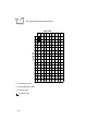
Appendix C. Character Sets
Character Set . . . . . . . . . . . . . . . . . . . . . . . . . . . . . . . . . . . . . . . . . . . . . . . . . . . . . . . . . . . . . . . . . C-1
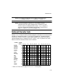
National Character Sets . . . . . . . . . . . . . . . . . . . . . . . . . . . . . . . . . . . . . . . . . . . . . . . . . . . . . . . . . C-3
Display Mode and Letter Size. . . . . . . . . . . . . . . . . . . . . . . . . . . . . . . . . . . . . . . . . . . . . . . . . . . . . C-4
Character Frame and Letter Size in Single-Byte ANK Mode . . . . . . . . . . . . . . . . . . . . . . . . . . C-4
Generating Small Font Patterns . . . . . . . . . . . . . . . . . . . . . . . . . . . . . . . . . . . . . . . . . . . . . . . . C-4
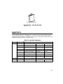
Appendix D. I/O Ports
Input Ports . . . . . . . . . . . . . . . . . . . . . . . . . . . . . . . . . . . . . . . . . . . . . . . . . . . . . . . . . . . . . . . . . . . D-1
Output Ports . . . . . . . . . . . . . . . . . . . . . . . . . . . . . . . . . . . . . . . . . . . . . . . . . . . . . . . . . . . . . . . . . D-4
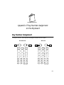
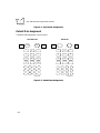
Appendix E. Key Number Assignment
on the Keyboard
Key Number Assignment . . . . . . . . . . . . . . . . . . . . . . . . . . . . . . . . . . . . . . . . . . . . . . . . . . . . . . . . E-1
Default Data Assignment. . . . . . . . . . . . . . . . . . . . . . . . . . . . . . . . . . . . . . . . . . . . . . . . . . . . . E-2
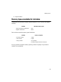
Appendix F. Memory Area
Memory Map . . . . . . . . . . . . . . . . . . . . . . . . . . . . . . . . . . . . . . . . . . . . . . . . . . . . . . . . . . . . . . . . . F-1
ROM (Flash ROM). . . . . . . . . . . . . . . . . . . . . . . . . . . . . . . . . . . . . . . . . . . . . . . . . . . . . . . . . F-2
RAM . . . . . . . . . . . . . . . . . . . . . . . . . . . . . . . . . . . . . . . . . . . . . . . . . . . . . . . . . . . . . . . . . . . . F-2
Memory Management . . . . . . . . . . . . . . . . . . . . . . . . . . . . . . . . . . . . . . . . . . . . . . . . . . . . . . . . . . F-2
Battery Backup of Memory. . . . . . . . . . . . . . . . . . . . . . . . . . . . . . . . . . . . . . . . . . . . . . . . . . . . . . . F-2
Memory Space Available for Variables . . . . . . . . . . . . . . . . . . . . . . . . . . . . . . . . . . . . . . . . . . . . . . F-3
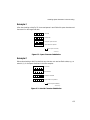
Appendix G. Handling Space
Characters in Downloading
Space Characters as Padding Characters. . . . . . . . . . . . . . . . . . . . . . . . . . . . . . . . . . . . . . . . . . . . . G-1
Space Characters as Data . . . . . . . . . . . . . . . . . . . . . . . . . . . . . . . . . . . . . . . . . . . . . . . . . . . . . . . . G-2
Example 1 . . . . . . . . . . . . . . . . . . . . . . . . . . . . . . . . . . . . . . . . . . . . . . . . . . . . . . . . . . . . . . . . G-3
Example 2 . . . . . . . . . . . . . . . . . . . . . . . . . . . . . . . . . . . . . . . . . . . . . . . . . . . . . . . . . . . . . . . . G-3
Example 3 . . . . . . . . . . . . . . . . . . . . . . . . . . . . . . . . . . . . . . . . . . . . . . . . . . . . . . . . . . . . . . . . G-4
ix
PDT 1100 Programmer’s Guide
Appendix H. Programming Notes
Sleep Timer . . . . . . . . . . . . . . . . . . . . . . . . . . . . . . . . . . . . . . . . . . . . . . . . . . . . . . . . . . . . . . . . . . H-1
Resume Function . . . . . . . . . . . . . . . . . . . . . . . . . . . . . . . . . . . . . . . . . . . . . . . . . . . . . . . . . . . . . . H-2
Low Battery Warning . . . . . . . . . . . . . . . . . . . . . . . . . . . . . . . . . . . . . . . . . . . . . . . . . . . . . . . . . . H-2
Selecting a Communications Device File . . . . . . . . . . . . . . . . . . . . . . . . . . . . . . . . . . . . . . . . . . . . H-3
Prohibited Simultaneous Operations . . . . . . . . . . . . . . . . . . . . . . . . . . . . . . . . . . . . . . . . . . . . . . . H-3
Controlling the LCD Backlight . . . . . . . . . . . . . . . . . . . . . . . . . . . . . . . . . . . . . . . . . . . . . . . . . . . H-3
Keyboard (Keypad) . . . . . . . . . . . . . . . . . . . . . . . . . . . . . . . . . . . . . . . . . . . . . . . . . . . . . . . . . . . . H-3
Beeper . . . . . . . . . . . . . . . . . . . . . . . . . . . . . . . . . . . . . . . . . . . . . . . . . . . . . . . . . . . . . . . . . . . . . . H-4
RS/CS Control . . . . . . . . . . . . . . . . . . . . . . . . . . . . . . . . . . . . . . . . . . . . . . . . . . . . . . . . . . . . . . . . H-4
Supplemental Codes. . . . . . . . . . . . . . . . . . . . . . . . . . . . . . . . . . . . . . . . . . . . . . . . . . . . . . . . . . . . H-4
Flash ROM . . . . . . . . . . . . . . . . . . . . . . . . . . . . . . . . . . . . . . . . . . . . . . . . . . . . . . . . . . . . . . . . . . H-4
Storing Files . . . . . . . . . . . . . . . . . . . . . . . . . . . . . . . . . . . . . . . . . . . . . . . . . . . . . . . . . . . . . . H-5
Deleting Files . . . . . . . . . . . . . . . . . . . . . . . . . . . . . . . . . . . . . . . . . . . . . . . . . . . . . . . . . . . . . H-5
Specifying Files . . . . . . . . . . . . . . . . . . . . . . . . . . . . . . . . . . . . . . . . . . . . . . . . . . . . . . . . . . . . H-5
Memory Areas Required for User Programs . . . . . . . . . . . . . . . . . . . . . . . . . . . . . . . . . . . . . . H-5
Retained Contents of Flash ROM. . . . . . . . . . . . . . . . . . . . . . . . . . . . . . . . . . . . . . . . . . . . . . H-6
Wake-up Function . . . . . . . . . . . . . . . . . . . . . . . . . . . . . . . . . . . . . . . . . . . . . . . . . . . . . . . . . . . . . H-6
LED and Beeper Control . . . . . . . . . . . . . . . . . . . . . . . . . . . . . . . . . . . . . . . . . . . . . . . . . . . . . . . . H-6
Controlling Reading Confirmation LED . . . . . . . . . . . . . . . . . . . . . . . . . . . . . . . . . . . . . . . . . H-6
Controlling the Beeper . . . . . . . . . . . . . . . . . . . . . . . . . . . . . . . . . . . . . . . . . . . . . . . . . . . . . . H-7
APLINT.PD3 Program File . . . . . . . . . . . . . . . . . . . . . . . . . . . . . . . . . . . . . . . . . . . . . . . . . . . . . . H-7
Modifying PW Key Depression . . . . . . . . . . . . . . . . . . . . . . . . . . . . . . . . . . . . . . . . . . . . . . . . . . . H-7
CODE128 Reading . . . . . . . . . . . . . . . . . . . . . . . . . . . . . . . . . . . . . . . . . . . . . . . . . . . . . . . . . . . . H-8
Field Length Restriction. . . . . . . . . . . . . . . . . . . . . . . . . . . . . . . . . . . . . . . . . . . . . . . . . . . . . . . . . H-8
Appendix I. Backlight Function
Appendix J. Program Samples
Writing a Function. . . . . . . . . . . . . . . . . . . . . . . . . . . . . . . . . . . . . . . . . . . . . . . . . . . . . . . . . . . . . . J-1
Testing the Written Function . . . . . . . . . . . . . . . . . . . . . . . . . . . . . . . . . . . . . . . . . . . . . . . . . . . . . . J-3
Appendix K.
Quick Reference for Statements and Functions
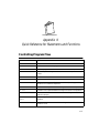
Controlling Program Flow . . . . . . . . . . . . . . . . . . . . . . . . . . . . . . . . . . . . . . . . . . . . . . . . . . . . . . . .K-1
Handling Errors. . . . . . . . . . . . . . . . . . . . . . . . . . . . . . . . . . . . . . . . . . . . . . . . . . . . . . . . . . . . . . . .K-2
Defining and Allocating Variables . . . . . . . . . . . . . . . . . . . . . . . . . . . . . . . . . . . . . . . . . . . . . . . . . .K-2
Controlling the LCD Screen. . . . . . . . . . . . . . . . . . . . . . . . . . . . . . . . . . . . . . . . . . . . . . . . . . . . . . .K-3
Controlling the Keyboard Input. . . . . . . . . . . . . . . . . . . . . . . . . . . . . . . . . . . . . . . . . . . . . . . . . . . .K-4
Beeping . . . . . . . . . . . . . . . . . . . . . . . . . . . . . . . . . . . . . . . . . . . . . . . . . . . . . . . . . . . . . . . . . . . . . .K-4
Manipulating System Date, Current Time, or Timers . . . . . . . . . . . . . . . . . . . . . . . . . . . . . . . . . . . K-5
x
Contents
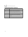
Communicating with I/Os . . . . . . . . . . . . . . . . . . . . . . . . . . . . . . . . . . . . . . . . . . . . . . . . . . . . . . . K-5
Communicating with Bar Code Device. . . . . . . . . . . . . . . . . . . . . . . . . . . . . . . . . . . . . . . . . . . . . . K-6
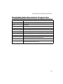
Manipulating Data Files and User Program Files . . . . . . . . . . . . . . . . . . . . . . . . . . . . . . . . . . . . . . K-7
Communicating with Communications Devices . . . . . . . . . . . . . . . . . . . . . . . . . . . . . . . . . . . . . . . K-8
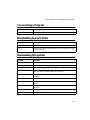
Commenting a Program . . . . . . . . . . . . . . . . . . . . . . . . . . . . . . . . . . . . . . . . . . . . . . . . . . . . . . . . . K-9
Manipulating Numeric Data. . . . . . . . . . . . . . . . . . . . . . . . . . . . . . . . . . . . . . . . . . . . . . . . . . . . . . K-9
Manipulating String Data . . . . . . . . . . . . . . . . . . . . . . . . . . . . . . . . . . . . . . . . . . . . . . . . . . . . . . . . K-9
Defining User-Created Functions . . . . . . . . . . . . . . . . . . . . . . . . . . . . . . . . . . . . . . . . . . . . . . . . . K-10
Specifying Included Files. . . . . . . . . . . . . . . . . . . . . . . . . . . . . . . . . . . . . . . . . . . . . . . . . . . . . . . . K-10
Appendix L.
Unsupported Statements and Functions
Appendix M. Communications
Basic Communications Specifications . . . . . . . . . . . . . . . . . . . . . . . . . . . . . . . . . . . . . . . . . . . . . . .M-1
Synchronization . . . . . . . . . . . . . . . . . . . . . . . . . . . . . . . . . . . . . . . . . . . . . . . . . . . . . . . . . . .M-1
Optical Interface Communications Range . . . . . . . . . . . . . . . . . . . . . . . . . . . . . . . . . . . . . . . .M-2
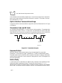
Transmission Code and Bit Order . . . . . . . . . . . . . . . . . . . . . . . . . . . . . . . . . . . . . . . . . . . . . .M-2
Response Method . . . . . . . . . . . . . . . . . . . . . . . . . . . . . . . . . . . . . . . . . . . . . . . . . . . . . . . . . .M-2
Vertical Parity . . . . . . . . . . . . . . . . . . . . . . . . . . . . . . . . . . . . . . . . . . . . . . . . . . . . . . . . . . . . .M-2
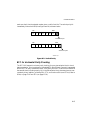
BCC for Horizontal Parity Checking . . . . . . . . . . . . . . . . . . . . . . . . . . . . . . . . . . . . . . . . . . . .M-3
IR Protocol . . . . . . . . . . . . . . . . . . . . . . . . . . . . . . . . . . . . . . . . . . . . . . . . . . . . . . . . . . . . . . .M-4
Communications Parameters . . . . . . . . . . . . . . . . . . . . . . . . . . . . . . . . . . . . . . . . . . . . . . . . . . M-5
In System Mode. . . . . . . . . . . . . . . . . . . . . . . . . . . . . . . . . . . . . . . . . . . . . . . . . . . . . . . . . . . .M-5
Communications Protocols. . . . . . . . . . . . . . . . . . . . . . . . . . . . . . . . . . . . . . . . . . . . . . . . . . . . . . .M-6
Protocol . . . . . . . . . . . . . . . . . . . . . . . . . . . . . . . . . . . . . . . . . . . . . . . . . . . . . . . . . . . . . . . . .M-6
IR Protocol . . . . . . . . . . . . . . . . . . . . . . . . . . . . . . . . . . . . . . . . . . . . . . . . . . . . . . . . . . . . . . . . . . M-21
Overview. . . . . . . . . . . . . . . . . . . . . . . . . . . . . . . . . . . . . . . . . . . . . . . . . . . . . . . . . . . . . . . .M-21
xi
PDT 1100 Programmer’s Guide
xii
About This Guide
The PDT 1100 Programmer’s Guide provides general instructions for programming the PDT
1100 terminal. The chapters are set up as follows:
!
!
!
!
!
!
!
!
!
!
!
Chapter 1, Software Overview surveys the software structure of the PDT 1100,
introduces the programs integrated in the ROM and the language features of BASIC
3.0.
Chapter 2, Development Environment and Procedures describes the hardware,
software, and procedures required for developing programs.
Chapter 3, Program Structure summarizes the basic structure of programs.
Chapter 4, Basic Program Elements describes the format of a program line, usable
characters, and labels.
Chapter 5, Data Types covers data which the program can handle by classifying them
into data types – constants and variables.
Chapter 6, Expressions and Operators surveys the expressions and operators to be
used for calculation and for handling character strings.
Chapter 7, I/O Facilities defines I/O facilities and describes output from the LCD,
input from the keyboard, and control for the timer, beeper, and other I/O’s by the
statements and functions.
Chapter 8, Files describes data files and device files.
Chapter 9, Event Polling and Error/Event Trapping describes the event polling and
two types of traps: error traps and event (of keystroke) traps supported by BASIC
3.0.
Chapter 10, Statement Reference describes the statements available in BASIC 3.0,
including the error codes and messages.
Chapter 11, Function Reference describes the functions available in BASIC 3.0,
including error codes and messages.
xiii
PDT 1100 Terminal Programmer’s Guide
!
!
!
!
!
!
!
!
!
!
!
!
!
Appendix A, Error Codes and Error Messages lists the error codes and messages.
Appendix B, Reserved Words lists the reserved words for BASIC 3.0.
Appendix C, Character Sets lists the character sets.
Appendix D, I/O Ports lists the I/O ports.
Appendix E, Key Number Assignment on the Keyboard shows the number
assignment for the keyboard.
Appendix F, Memory Area describes the memory area allocations.
Appendix G, Handling Space Characters in Downloading describes how to handle
different types of space characters during downloading.
Appendix H, Programming Notes describes specific programming tips.
Appendix I, Backlight Function describes how to use the backlight function.
Appendix J, Program Samples shows sample programs to use on the PDT 1100.
Appendix K, Quick Reference for Statements and Functions lists the statements and
functions by categories.
Appendix L, Unsupported Statements and Functions lists what MS-BASIC supports
that BASIC 3.0 does not.
Appendix M, Communications describes in detail the communications procedures
and parameters.
Notational Conventions
The following conventions are used in this document:
!
!
!
!
xiv
Italics are used to highlight specific items in the general text, and to identify chapters
and sections in this and related documents.
Bullets (♦) indicate:
" action items
" lists of alternatives
" lists of required steps that are not necessarily sequential
Sequential lists (e.g., those that describe step-by-step procedures) appear as
numbered lists.
Items in regular courier font indicate constant syntax, items in italic courier
font indicate variable syntax.
About This Guide
Service Information
If you have a problem with your equipment, contact the Symbol Support Centers. Before
calling, have the model number, serial number, and several of your bar code symbols at hand.
Call the Support Center from a phone near the scanning equipment so that the service person
can try to talk you through your problem. If the equipment is found to be working properly
and the problem is symbol readability, the Support Center will request samples of your bar
codes for analysis at our plant.
If your problem cannot be solved over the phone, you may need to return your equipment for
servicing. If that is necessary, you will be given specific directions.
Note: Symbol Technologies is not responsible for any damages incurred
during shipment if the approved shipping container is not used.
Shipping the units improperly can possibly void the warranty. If the
original shipping container was not kept, contact Symbol to have
another sent to you.
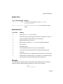
Symbol Support Centers
For service information, warranty information or technical assistance contact or call the
Symbol Support Center in:
United States
Symbol Technologies, Inc.
One Symbol Plaza
Holtsville, New York 11742-1300
1-800-653-5350
Canada
Symbol Technologies Canada, Inc.
2540 Matheson Boulevard East
Mississauga, Ontario, Canada L4W 422
(905) 629-7226
United Kingdom
Symbol Technologies
Symbol Place
Winnersh Triangle, Berkshire RG41 5TP
United Kingdom
0800 328 2424 (Inside UK)
+44 208 945 7529 (Outside UK)
Asia/Pacific
Symbol Technologies Asia, Inc.
230 Victoria Street #04-05
Bugis Junction Office Tower
Singapore 188024
337-6588 (Inside Singapore)
+65-337-6588 (Outside Singapore)
xv
PDT 1100 Terminal Programmer’s Guide
Australia
Symbol Technologies Pty. Ltd.
432 St. Kilda Road
Melbourne, Victoria 3004
1-800-672-906 (Inside Australia)
+61-3-9866-6044 (Outside Australia)
Austria/Österreich
Symbol Technologies Austria GmbH
Prinz-Eugen Strasse 70
Suite 3
2.Haus, 5.Stock
1040 Vienna, Austria
1-505-5794 (Inside Austria)
+43-1-505-5794 (Outside Austria)
Denmark/Danmark
Symbol Technologies AS
Gydevang 2,
DK-3450 Allerod, Denmark
7020-1718 (Inside Denmark)
+45-7020-1718 (Outside Denmark)
Europe/Mid-East Distributor Operations
Contact your local distributor or call
+44 208 945 7360
Finland/Suomi
Oy Symbol Technologies
Kaupintie 8 A 6
FIN-00440 Helsinki, Finland
9 5407 580 (Inside Finland)
+358 9 5407 580 (Outside Finland)
France
Symbol Technologies France
Centre d'Affaire d'Antony
3 Rue de la Renaissance
92184 Antony Cedex, France
01-40-96-52-21 (Inside France)
+33-1-40-96-52-50 (Outside France)
Germany/Deutchland
Symbol Technologies GmbH
Waldstrasse 68
D-63128 Dietzenbach, Germany
6074-49020 (Inside Germany)
+49-6074-49020 (Outside Germany)
Italy/Italia
Symbol Technologies Italia S.R.L.
Via Cristoforo Columbo, 49
20090 Trezzano S/N Navigilo
Milano, Italy
2-484441 (Inside Italy)
+39-02-484441 (Outside Italy)
xvi
About This Guide
Latin America Sales Support
7900 Glades Road
Suite 340
Boca Raton, Florida 33434 USA
1-800-347-0178 (Inside United States)
+1-561-483-1275 (Outside United States)
Netherlands/Nederland
Symbol Technologies
Kerkplein 2, 7051 CX
Postbus 24 7050 AA
Varsseveld, Netherlands
315-271700 (Inside Netherlands)
+31-315-271700 (Outside Netherlands)
Mexico/México
Symbol Technologies Mexico Ltd.
Torre Picasso
Boulevard Manuel Avila Camacho No 88
Lomas de Chapultepec CP 11000
Mexico City, DF, Mexico
5-520-1835 (Inside Mexico)
+52-5-520-1835 (Outside Mexico)
Norway/Norge
Symbol Technologies
Trollasveien 36
Postboks 72
1414 Trollasen, Norway
66810600 (Inside Norway)
+47-66810600 (Outside Norway)
If you purchased your Symbol product from a Symbol Business Partner, contact that Business
Partner for service.
Related Publications
!
!
!
!
PDT 1100 Terminal Product Reference Guide p/n 70-35864-XX
PDT 1100 Quick Reference Guide p/n 70-35861-XX
PDT 1100 Terminal Transfer Utilities Guide p/n 70-36368-XX
PDT 1100 Extension Library Programmer’s Guide p/n 70-36556-XX
Warranty
Symbol Technologies, Inc (“Symbol”) manufactures its hardware products in accordance with industrystandard practices. Symbol warrants that for a period of twelve (12) months from date of shipment,
products will be free from defects in materials and workmanship.
xvii
PDT 1100 Terminal Programmer’s Guide
This warranty is provided to the original owner only and is not transferable to any third party. It shall
not apply to any product (i) which has been repaired or altered unless done or approved by Symbol, (ii)
which has not been maintained in accordance with any operating or handling instructions supplied by
Symbol, (iii) which has been subjected to unusual physical or electrical stress, misuse, abuse, power
shortage, negligence or accident or (iv) which has been used other than in accordance with the product
operating and handling instructions. Preventive maintenance is the responsibility of customer and is not
covered under this warranty.
Wear items and accessories having a Symbol serial number, will carry a 90-day limited warranty. Nonserialized items will carry a 30-day limited warranty.
Warranty Coverage and Procedure
During the warranty period, Symbol will repair or replace defective products returned to Symbol’s
manufacturing plant in the US. For warranty service in North America, call the Symbol Support Center
at 1-800-653-5350. International customers should contact the local Symbol office or support center.
If warranty service is required, Symbol will issue a Return Material Authorization Number. Products
must be shipped in the original or comparable packaging, shipping and insurance charges prepaid.
Symbol will ship the repaired or replacement product freight and insurance prepaid in North America.
Shipments from the US or other locations will be made F.O.B. Symbol’s manufacturing plant.
Symbol will use new or refurbished parts at its discretion and will own all parts removed from repaired
products. Customer will pay for the replacement product in case it does not return the replaced product
to Symbol within 3 days of receipt of the replacement product. The process for return and customer’s
charges will be in accordance with Symbol’s Exchange Policy in effect at the time of the exchange.
Customer accepts full responsibility for its software and data including the appropriate backup thereof.
Repair or replacement of a product during warranty will not extend the original warranty term.
Symbol’s Customer Service organization offers an array of service plans, such as on-site, depot, or phone
support, that can be implemented to meet customer’s special operational requirements and are available
at a substantial discount during warranty period.
General
Except for the warranties stated above, Symbol disclaims all warranties, express or implied, on products
furnished hereunder, including without limitation implied warranties of merchantability and fitness for
a particular purpose. The stated express warranties are in lieu of all obligations or liabilities on part of
Symbol for damages, including without limitation, special, indirect, or consequential damages arising
out of or in connection with the use or performance of the product.
Seller’s liability for damages to buyer or others resulting from the use of any product, shall in no way
exceed the purchase price of said product, except in instances of injury to persons or property.
Some states (or jurisdictions) do not allow the exclusion or limitation of incidental or consequential
damages, so the preceding exclusion or limitation may not apply to you.
xviii
Chapter 1 Software Overview
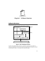
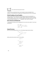
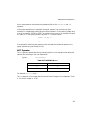
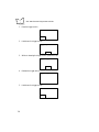
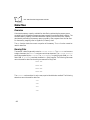
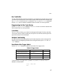
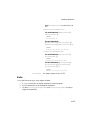
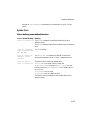
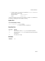
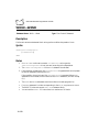
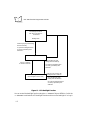
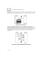
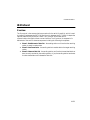
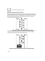
Software Structure
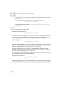
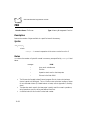
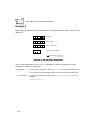
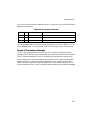
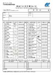
The structure of software for the PDT 1100 is shown in Figure 1-1.
RAM or flash ROM
User programs
Application
programs
Extension programs
Flash ROM
System
programs
System Mode
BASIC 3.0 Interpreter
Font files
Drivers
Hardware
36099001.eps
Figure 1-1. PDT 1100 Software Structure
The PDT 1100 has flash ROM and RAM. In flash ROM reside the drivers, BASIC 3.0
Interpreter, System Mode, and font files. Extension programs and user programs are stored
in the user area of RAM (or in the flash ROM) when downloaded.
1-1
PDT 1100 Terminal Programmer’s Guide
Note: Unlike RAM, the flash ROM requires no power for retaining stored
files. Therefore, leaving the PDT 1100 with no battery cartridge or
dry batteries loaded do not damage files stored in the flash ROM
while it may damage files in the RAM.
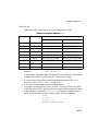
Unlike RAM, the flash ROM is limited in the following ways:
!
!
!
The quantity of rewriting operations is limited to approximately 10,000.
In application programs, you cannot write data onto the flash ROM.
The user area is 568 kilobytes or 64 kilobytes (depending upon the ROM size). (For
details, refer to Appendix F, Memory Area.)
System Programs
Drivers
The BASIC 3.0 Interpreter or System Mode calls a set of programs which controls the
hardware. The drivers include the Decoder Software used for bar code reading.
BASIC 3.0 Interpreter
Interprets and executes user programs or Easy Pack.
System Mode
Sets up the execution environment for user programs or Easy Pack.
Extension Programs
Enable the following functions of the BASIC 3.0:
!
!
Displays ruled lines on the LCD
Transmits/receives files using the X-MODEM and Y-MODEM protocols.
These extension programs are stored in files having an FN3 extension, in each file per
function. Download a xxxx.FN3 file containing the necessary function from the BASIC 3.0
Extension Library to the user area.
1-2
Software Overview
Application Programs
User Programs
User-written object programs which are ready to be executed.
Easy Pack
Application program used for bar code data collection.
Overview of BASIC 3.0
With BASIC 3.0, you can customize application programs to meet specific needs:
!
!
!
!
!
!
!
Retrieve products names, price information, etc. in a master file.
Include check digits in bar code reading to make a checking procedure more reliable.
Improve the checking procedure by checking the number of digits entered from the
keyboard.
Calculate (e.g., subtotals and totals).
Support file transmission protocols (or transmission procedures) suitable for host
computers and connected modems.
Download master files.
Support a program to transfer control to several job programs depending upon
conditions.
BASIC 3.0
Features
BASIC 3.0 is an optimal programming language to make application programs for the PDT
1100 and to enable efficient program development, with the following features:
Syntax Similar to Microsoft ® BASIC
BASIC 3.0 is based on the BASIC language which is the most widely used high-level language.
The syntax of BASIC 3.0 is very similar to that used in Microsoft BASIC (MS-BASIC), the
practical standard of the BASICs running on personal computers over the world.
1-3
PDT 1100 Terminal Programmer’s Guide
No Line Numbers Required
Like Microsoft Quick BASIC, BASIC 3.0 requires no line number notation. You can write a
branch statement with a label instead of a line number so cut and paste functions can be used
with an editor in developing source programs, facilitating the use of program modules for
development of other programs.
MS-DOS Programming Environment
Any MS-DOS personal computer can be used to develop programs with BASIC 3.0.
Advantages of the Dedicated Compiler
The dedicated compiler (referred to as the Compiler hereafter) checks the syntax of the edited
source program on an MS-DOS personal computer, enabling efficient debugging in program
development. It also outputs debugging information including cross reference lists of
variables and labels.
The Compiler assigns variables to fixed addresses so the Interpreter does not have to allocate
or release memories when executing user programs, shortening execution time.
Program Compression by the Dedicated Compiler
The Compiler compresses a source program into the intermediate language to produce an
object program (a user program).
Note: When the compiled user program is downloaded to the PDT 1100, it
packs the two-byte data in the intermediate language into a singlebyte hexadecimal format for more efficient use of the memory area in
the PDT 1100.
Compilation and Program Execution
Compiler and Interpreter
BASIC 3.0 consists of the Compiler and the Interpreter.
Compiler
The Compiler development tool compiles a source program written on an MS-DOS personal
computer to generate a “user program” in the intermediate language. The Compiler is
optionally provided in an MS-DOS format floppy disk which contains the following three
1-4
Software Overview
files: BHTC3.EXE (MS-DOS–based Compiler), BHTC3W.EXE (Windows-based Compiler),
and BHTC3.MSG (Message file).
The Compiler checks the syntax of a source program during compilation and outputs syntax
errors, if any, to the MS-DOS standard output device. When the Compiler finds no syntax
error in the source program, it translates the program into the intermediate language.
Interpreter
The Interpreter, which resides in the memory of the PDT 1100, interprets and executes the
user program downloaded to the PDT 1100, statement by statement.
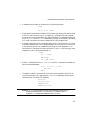
Compiling and Interpreting Example
For example, how will a short program consisting of only two statements, CLS and END, be
compiled, downloaded, and executed?
Source Program Example:
CLS
END
1. The Compiler compiles each of the CLS and END statements into a two-byte character
string in the intermediate language in an MS-DOS disk file. In this example, the total
four-byte string is composed of 83 and 87 whose program is:
“8387”
The compiled program should consist of ASCII characters (text) : 0-9 and A-F.
2. The user downloads the four-byte string 8387, using Transfer Utility C. Upon receipt
of the string, the PDT 1100 packs each two bytes into a single-byte hexadecimal
format: 83h and 87h.
3. The Interpreter interprets the first 83h as a CLS statement and 87h as an END
statement.
1-5
PDT 1100 Terminal Programmer’s Guide
1-6
Chapter 2
Development Environment and Procedures
Overview of Development Environment
The following hardware and software are required for developing user programs:
Required Hardware
!
!
!
!
A Windows personal computer with an RS-232C interface and at least 640-kilobyte
RAM area is required. When the Compiler is running, at least 400 kilobytes should
be reserved in RAM as a work area.
PDT 1100 terminal
CRD 1100 (Optical communications unit/cradle) (not required if the PDT 1100 is
directly connected with the personal computer via the direct-connect interface)
RS-232C interface cable connects the CRD 1100 to the personal computer.
Note: The RS-232C interface cable must have the connector and pin
assignment required by the personal computer. See the PDT 1100
Product Reference Guide for connector configuration and pin
assignments of the CRD 1100.
2-1
PDT 1100 Terminal Programmer’s Guide
Required Software
• MS Windows(OS)
Windows 95/NT 3.51.40
• Editor
• BASIC 3.0 Compiler
BHTC3W.EXE (Windows-based)
BHTC3.MSG (Error message file)
• Ir-Transfer Utility C (option)
TU3W.EXE (Windows-based)
TU3C2W.EXE (Windows based)
• Ir-Transfer Utility E (option)
ITEW32.EXE (Windows- based)
Ir-Transfer Utility C and IR Transfer Utility E download user programs to the PDT 1100. The
BASIC 3.0 Compiler, Ir-Transfer Utility C and Ir-Transfer Utility E are optionally provided in
a floppy disk.
Note: Prepare Windows and editor versions operable with the personal
computer on which user programs are to be developed.
For the manufacturers and models of Windows computers which
support Ir-Transfer Utility C and E, refer to the PDT 1100 Terminal
Transfer Utility Guide.
Overview of Developing Procedures
Developing Procedures
The program developing procedures using BASIC 3.0 are outlined below.
Creating a Source Program
Create a source program using an editor according to the syntax of BASIC 3.0.
Compiling
Compile the source program by the Compiler to generate a user program (an object
program).
Downloading the User Program
Download the user program to the PDT 1100 by using Ir-Transfer Utility C.
2-2
Development Environment and Procedures
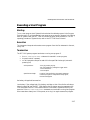
Executing the User Program
Execute the user program on the PDT 1100.
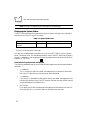
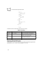
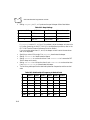
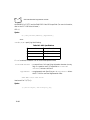
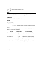
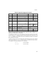
Functions of the Compiler
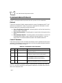
The Compiler has the following functions:
Functions of the Compiler
Description
Syntax check
Detects syntax errors in source programs.
Output of a user program
Translates a source program into a user program in intermediate
language. (When downloaded to the PDT 1100 by Ir-Transfer
Utility C, the user program is packed to be executed by the
Interpreter.)
Output of debug information
Outputs list files and debug information files.
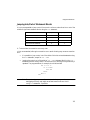
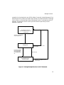
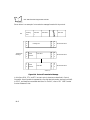
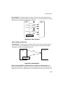
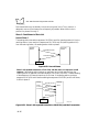
Developing Procedure Flow
The steps below shows the developing procedure.
On an Windows Personal Computer
1. Write a source program.
C>EDIT userprog.SRC
CLS
PRINT “BASIC 3.0”
END
(Tool: Editor)
2. Compile the source program.
C>BHTC3 userprog.SRC
(Tool: BASIC 3.0 Compiler)
If a compilation error occurs, go back to step 1 and correct the program. If no
compilation error occurs and the user program is generated, proceed to step 3.
3. Download the user program.
C>TU3 userprog.PD3
(Tool: Transfer Utility C)
2-3
PDT 1100 Terminal Programmer’s Guide
C>IT3C userprog.PD3
(Tool: Ir-Transfer Utility C)
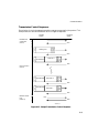
On the PDT 1100
Execute the user program in System Mode.
EXECUTE PROGRAM
A:USERPROG.PD3
If an execution error occurs, execute the program again.
Writing of a Source Program
Writing a Source Program Using Editor
To write a source program, use an editor designed for an Windows personal computer (use
of a commercially available editor is recommended). See the instruction manual for the editor
for information on its use.
C>EDIT prog1.SRC
If you place an extension .SRC in a source program file, you may omit the filename extension
in compilation.
C>BHTC3 prog1
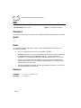
Rules for Writing a Source Program
When writing a source program according to the syntax of BASIC 3.0, observe the following
rules:
!
A label name should begin in the first column.
ABC
2000
2-4
Development Environment and Procedures
!
A statement should begin in the second or the following columns.
PRINT
FOR I=1 TO 100 : NEXT I
!
!
One program line should be limited to 512 characters (excluding a CR code) and end
with a CR code (the return key). If an underline (_) precedes a CR code, however,
one program line can be extended up to 8192 characters. For statements other than
the PRINT, PRINT#, and PRINT USING statements, you may use a comma (,) preceding
a CR code. A program can contain a maximum of 9,999 program lines.
Comment lines starting with a single quotation mark (') and those with a REM have
the following description rules. A single quotation mark can be put in from the first
or the following columns, or immediately following any other statement. A REM
should be put in the second or following columns. To put a REM following any other
statement, a colon (:) should precede the REM.
Comment
CLS ' ‘ Comment
REM Comment
CLS :: REM Comment
!
End the IF statement with an END IF or ENDIF, since the IF statement is treated as a
block-structured statement.
IF a$ = “Y” OR a$ = “y” then
GOTO sub12
END IF
!
The default number of characters for a non-array string variable is 40 and for an
array string variable is 20. Specifying the DIM or DEFREG statement allows a string
variable to treat 1 through 255 characters.
DIM b$[255]
DIM c$(2,3)[255]
DEFREG d$[255]
DEFREG e$(2,3)[255]
Note: BASIC 3.0 does not support some of the statements and functions
used in Microsoft BASIC or QuickBASIC. For details, refer to
Appendix L, Unsupported Statements and Functions.
2-5
PDT 1100 Terminal Programmer’s Guide
Compiling in Windows
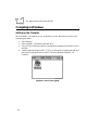
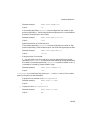
Setting up the Compiler
Set up the BASIC 3.0 Compiler on your computer to run with Windows according to the
procedure given below.
1. Start Windows.
2. Insert the BASIC 3.0 diskette in the disk drive.
3. Copy all files in the directory WIN on the diskette to the appropriate directory of the
hard disk.
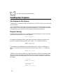
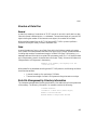
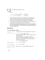
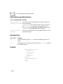
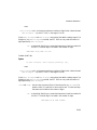
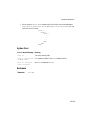
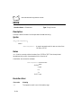
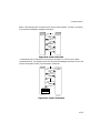
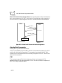
4. Create an appropriate group (BHT_TOOL, for example) in Program Manager, and
then specify the program-item icon BHTC3W that represents the BASIC 3.0
Compiler.
36099002.eps
Figure 2-1. BHT-TOOL group
2-6
Development Environment and Procedures
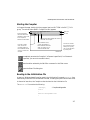
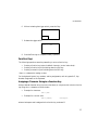
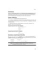
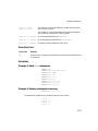
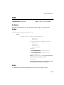
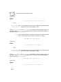
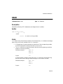
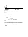
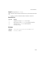
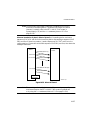
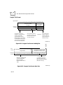
Starting the Compiler
In Program Manager, double-click the program-item icon BHTC3W in the BHT_TOOL
group. The main window (BASIC Compiler for Win) appears.
Menu bar
From the File menu,
choose the Select File
command to select a file
to be compiled or
execute the selected file.
From the Compile
menu, choose the
Compiling Options or
Run command to set the
options or execute the
Compiler.
Tool bar
From the Help menu, display the version of
the BASIC 3.0 Compiler.
From the Editor menu,
choose the Set Editor or
Edit command to select the
editor you want to run or
start the selected editor.
The tool bar contains
the tool buttons which
enable you to quickly
carry out the functions
by clicking them.
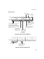
36099003.eps
Immediately executes the Compiler if a filename is specified. (If no filename is
specified, you cannot choose this button.)
Starts the editor selected by the Set Editor command in the Editor menu.
Opens the Select File dialog box.
Reading in the Initialization File
At start-up, Windows-based Compiler reads in the initialization file named BHTC3W.INI from
the directory where the file to be executed is located, for setting the options and window sizes.
At the end of execution, the Compiler writes the data into the initialization file.
The BHTC3W.INI file contains the following:
[Settings]
.. Compiler setting section
List=0
:
Editor=c:¥winapl¥edit.exe
:
2-7
PDT 1100 Terminal Programmer’s Guide
[Windows]
AppPosX=100
:
.. Windows' location & size section
Caution
Never modify the contents of the initialization file BHTC3W.INI.
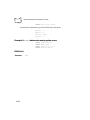
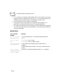
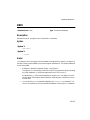
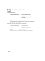
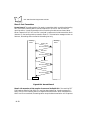
Operating Procedure for the Compiler
Selecting the File to be Compiled
Select a file to compile using one of the following methods:
!
From the File menu, choose the Select File command.
!
While holding down the Ctrl key, press the S key.
Click the file selection button
in the tool bar.
!
36099007.eps
Figure 2-2. Select File Dialog Box
2-8
Development Environment and Procedures
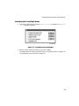
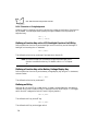
Specifying the Compiling Options
1. From the Compile menu, choose the Compiling Options command. The Compiling
Options dialog box appears.
36099008.eps
Figure 2-3. Compiling Options Dialog Box
2. Select the check boxes of the options you want to specify.
For details about the compiling options, refer to Compiling Options on page 2-14
and Generating a User Program on page 2-12.
2-9
PDT 1100 Terminal Programmer’s Guide
Executing the Compiler
Execute the Compiler using one of the following methods:
!
!
!
!
!
In the Select File dialog box, click the Run button.
From the Compile menu, choose the Run command.
While holding down the Ctrl key, press the G key.
In the Compiling Options dialog box, click the Run button.
Click the compile start button
in the tool bar.
Note: If the compiling options have been set, you can easily start the
Compiler by the Windows' drag-and-drop method, that is, dragging a
file to be compiled in File Manager onto the Compiler icon.
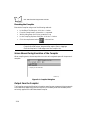
Screen Shown During Execution of the Compiler
When compiling starts, the mouse pointer turns into an hourglass shape until the process is
complete.
Compiling the test TEST.SRC
36099010.eps
Figure 2-4. Compiler Dialog Box
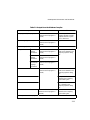
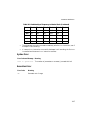
Output from the Compiler
The Compiler outputs the following information as well as user programs (object programs)
to the destination depending upon the conditions. Enclosed by bold lines are descriptions
exclusively applied to the Windows-based Compiler.
2-10
Development Environment and Procedures
Table 2-1. Output from the Windows Compiler
Output
Destination
Conditions
User program (object program)
File XXX.PD3 (in the directory When the specified source
where the source program is
program has been normally
located)
compiled without a syntax
error or fatal error.
Error message (Syntax error)
File XXX.ERR (in the directory A syntax error is detected.
where the source program is
located)
Error message (Fatal error)
Main Window
Debug information
File XXX.ADR (in the directory The Debug information file
check box is selected in the
where the source program is
Compiling Options dialog
located)
box.
File XXX.LBL (in the directory
where the source program is
located)
Source line–
Address
information
Label–
Address
information
Variable–
Intermediate
language
information
Address–Source list
A fatal error is detected.
File XXX.SYM (in the directory
where the source program is
located)
File XXX.LST (in the directory The Address-source List
check box is selected in the
where the source program is
Compiling Options dialog
located)
box.
Symbol table
The Symbol table check box is
selected in the Compiling
Options dialog box.
Cross reference
The X (Cross) reference check
box is selected in the
Compiling Options dialog
box.
Sizes of variables
File XXX.ERR (in the directory The Variable size check box is
selected in the Compiling
where the source program is
Options dialog box.
located).
XXX represents a source program filename.
2-11
PDT 1100 Terminal Programmer’s Guide
Displaying the Compile Result Files (XXX.ERR)
Set the editor to display the XXX.ERR files generated by the Compiler:
1. From the Editor menu, choose Set Editor.
Figure 2-5. Editor Menu
The Set Editor dialog box appears as shown below.
Figure 2-6. Set Editor Dialog Box
2. In the Command Line box, type the filename of the editor. If the editor is not located
in the current directory or working directory, type the directory name. If you don't
know the filename of the editor or the directory name, choose the Browse button in
the Set Editor dialog box to display the Browse dialog box. Select the appropriate
filename from the list, and choose the OK button.
Generating a User Program
Use the same procedure as the Windows–based Compiler. Refer to Screen Shown During
Execution of the Compiler on page 2-10.
Error Messages
The Compiler may detect two types of compilation errors: syntax errors and fatal errors. The
contents of the error output is the same as for the Windows–based Compiler.
2-12
Development Environment and Procedures
Syntax Errors
If the Compiler detects a syntax error, it outputs the error message to the XXX.ERR file
opened by the editor preset by the Set Editor command in the Editor menu. The total number
of the detected syntax errors appears on the main window.
Compiling the test TEST.SRC
0002 Error Statement Compiled End
36099010.eps
Figure 2-7. Syntax Error Screen
Fatal Errors
If the Compiler detects a fatal error, it outputs the error message to the main window.
Compiling the test TEST.SRC
fatal error 30: Cannot find include file “XXX”
36099010.eps
Figure 2-8. Fatal Error Screen
ERRORLEVEL
The Windows-based Compiler does not support the ERRORLEVEL function.
2-13
PDT 1100 Terminal Programmer’s Guide
Outputting Error Messages and Variables Size (if selected)
The Compiler outputs error messages (if any) and variables size (if selected) to the XXX.ERR
file. After compilation, if the XXX.ERR file has been made, the Compiler automatically
opens the file by the preset editor. The default editor is the notepad.exe provided with
Windows.
Using an editor with the tag-jump function allows you to efficiently correct the source
program file which caused an error. For details about the tag-jump function, refer to the
user's manual of the editor.
36099013.eps
Figure 2-9. TEST.ERR Screen
Compiling Options
Specifying the check box option in the Compiling Options dialog box causes the Compiler to
output the specified debug information or list files.
For details, refer to Generating a User Program on page 2-12.
Table 2-2. List of Compiling Options Available
Compiling
Options
Description
Debug
Outputs a debug information file. If this option is not selected, no debug
information file information file is output (default).
(For details, refer to the +D option in the Windows–based Compiler.)
Address-source
List
Outputs an address-source list to the file XXX.LST. If this option is not
selected, no address-source list is output (default).
(For details, refer to the +L option in the Windows–based Compiler.)
Symbol table
Outputs a symbol table to the file XXX.LST. If this option is not selected, no
symbol table is output (default).
(For details, refer to the +S option in the Windows– based Compiler.)
2-14
Development Environment and Procedures
Table 2-2. List of Compiling Options Available (Continued)
Compiling
Options
Description
X (Cross)
reference
Outputs a cross reference to the file XXX.LST. If this option is not selected, no
cross reference is output (default).
(For details, refer to the +X option in the Windows–based Compiler.)
Variable size
Outputs the sizes of common variables, work variables, and register variables
to the file XXX.ERR. If this option is not selected, no variable size is output
(default).
(For details, refer to the +V option in the Windows–based Compiler.)
[Example]
C>BHTC3 prog2 +V
The output for this example is as follows:
Common = XXXXX bytes (XXXXX bytes on memory. XXXXX bytes in file)
Work = XXXXX bytes (XXXXX bytes on memory. XXXXX bytes in file)
Register = XXXXX bytes in file
The Windows-based Compiler does not support the +W option available in the Windows
version.
Designating the Work Drive and Directory
Designate the work drive and directory of the Compiler by setting the Windows
environmental variables. If you don't designate them, the Compiler creates a directory
according to the priority below.
1. In the directory set in the TMP.
2. In the directory set in the TEMP. (The Windows version does not refer to this
environmental variable.)
3. In the directory where the Compiler is located, if no work drive or directory has been
set in both the TMP and TEMP or if invalid values have been specified in them.
During compilation, the Compiler creates a work file in the directory as defined above. After
compilation, it erases the work file.
2-15
PDT 1100 Terminal Programmer’s Guide
Downloading
Ir-Transfer Utility C & Ir-Transfer Utility E
Ir-Transfer Utility C & E transfers user programs and data files (e.g., master files) between
the PDT 1100 and the connected Windows personal computer. It has the following functions:
!
!
!
!
!
Downloading extension programs
Downloading programs
Downloading data
Uploading programs
Uploading data.
For operations of Ir-Transfer Utility C & E, refer to the PDT 1100 Terminal Transfer Utility
Guide.
Setting up the PDT 1100
Before downloading user programs, initialize the RAM and flash ROM if the error message
below appears.
“System error ! Contact your administrator. Note the error
drive. (DRIVE x)”
This message appears in the following cases:
!
!
The PDT 1100 is first powered on from the time of purchase.
The PDT 1100 is powered on after being left without battery cartridge loaded for a
long time.
Caution
Initialization erases all programs and data stored in the RAM and flash
ROM and resets the system calendar clock and communications parameters
to their defaults. Therefore, set those reset parameters in System Mode before accessing the download menu.
For details about initialization and downloading, refer to the PDT 1100 Terminal Product
Reference Guide.
2-16
Development Environment and Procedures
Executing a User Program
Starting
To run a user program, start System Mode and select the desired program in the Program
Execution menu. If you have selected a user program as an execution program in the Setting
menu of System Mode, the PDT 1100 runs the user program when powered on. For the
operating procedure of System Mode, refer to the PDT 1100 User's Manual.
Execution
The Interpreter interprets and executes a user program from the first statement to the next,
one by one.
Termination
The PDT 1100 system program terminates a running user program if:
!
!
!
the END, POWER OFF, or POWER 0 statement is executed in a user program,
the power switch is pressed,
no valid operations are performed within the specified time length (automatic
powering-off)
Valid operations:
- Entry by pressing any key
- Bar code reading by pressing the trigger switch
- Data transmission
- Data reception
Specified time length:
Length of time specified by the POWER statement
in the user program. If not specified in the program,
three minutes applies.
the battery voltage level becomes low.
Low battery: If the voltage level of the battery cartridge or that of the alkaline cells drops
below the specified level, the PDT 1100 displays the low battery warning message on the
LCD and powers itself off. If the resume function is activated in System Mode, only the
execution of the END, POWER OFF, or POWER 0 statement can terminate a running user program.
Other cases above merely turn off the power, so turning it on again resumes the program.
2-17
PDT 1100 Terminal Programmer’s Guide
2-18
Chapter 3 Program Structure
Statement Blocks
A statement block is a significant set of statements (also called “program routine”). The
following types of statement blocks are available in programming the PDT 1100:
Subroutines
A subroutine is a statement block called from the main routine or other subroutines by the
GOSUB statement.
Using the RETURN statement passes control from the called subroutine back to the statement
immediately following the GOSUB statement in the original main routine or subroutine.
Error-/Event-Handling Routines
An error- or event-handling routine is a statement block to which program control passes
when an error trap or event (of keystroke) trap occurs during program execution,
respectively.
The RESUME statement passes control from the error-handling routine back to the desired
statement.
The RETURN statement in the keyboard interrupt event-handling routine returns control to the
statement following the one that caused the interrupt.
Block-Format User-Defined Functions
A user-defined function comes in two formats: one-line format and block format, both of
which can be called from the main routine or subroutines. (Before calling user-defined
functions, it is necessary to define those functions by DEF FN statements.)
3-1
PDT 1100 Terminal Programmer’s Guide
The block-format user-defined function has the same structure as a statement block.
Generally, it should be placed at the beginning of a program before the main routine starts.
Global Variables and Local Variables
Global variables may be accessed by the same variable's name from any statement in a
complete program. They include work variables, register variables, and common variables.
Local variables are valid only within individual statement blocks where each of them is used.
A dummy argument defined by the DEF FN statement is one of the local variables.
Block-Structured Statements
The statements listed below have the statement block structure and are useful for structured
programming.
FOR...NEXT
IF...THEN...ELSE...END IF
SELECT...CASE...END SELECT
WHILE...WEND
Nested Structure
Block-structured statements allow you to write nesting programs as shown below.
FOR i=1 TO 10
FOR j=2 TO 10 STEP 2
PRINT i, j, k
NEXT j
NEXT i
Nesting subroutines as shown below is also possible.
GOSUB aaa
:
aaa
PRINT “aaa”
GOSUB bbb
RETURN
bbb
PRINT “bbb”
RETURN
3-2
Program Structure
Jumping Into/Out of Statement Blocks
It is not recommended to jump control from a main routine or subroutines into or out of the
middle of significant statement blocks using the GOTO statement.
Statement Blocks
Jump into
Jump out
Subroutine
X
X
Error-/event-handling routine
X
X
Block-format user-defined function
X
X
Block-structured statement
X
z
X : To be avoided. An execution error may occur.
z: Not recommended, although no execution error results. Nesting may cause an execution
error.
!
!
It is possible to jump control out of the midst of block-structured statements using
the GOTO statement, except for FOR...NEXT.
Jumping the control out of the midst of FOR...NEXT statement block by the GOTO
statement does not directly result in an execution error, although it may eventually if
repeated. The program below, for example, should be avoided.
FOR I%=0 TO 10
IF I%=5 THEN
GOTO AAA
ENDIF
NEXT I%
AAA
Note: Frequent or improper use of GOTO statements in a program decreases
debugging efficiency and might cause fatal execution errors. Avoid
using GOTO statements, if possible.
3-3
PDT 1100 Terminal Programmer’s Guide
Handling User Programs
User Programs in the Memory
The user area of the memory (RAM and flash ROM) in the PDT 1100 can store more than
one user program.
If you have selected a user program as an execution program in the Setting menu of System
Mode, the PDT 1100 runs the user program when powered on. For the operating procedure
of System Mode, refer to the PDT 1100 Terminal Product Reference Guide
.
Program Chaining
Program chaining, caused by the CHAIN statement below, terminates a currently running user
program and transfers control to another program.
CHAIN “another.PD3”
To transfer the variables and their values used in the current calling user program to the
chained-to program along the program chain, use the COMMON statement as follows:
COMMON a$(2),b,c%(3)
CHAIN “another.PD3”
The Interpreter writes these declared variable values into the “common variable area” in
memory. To make the chained-to program refer to these values, use the COMMON statement
again.
COMMON a$(2),b,c%(3)
In BASIC 3.0, the name, type, definition order, and number of COMMON-declared variables
used in the current calling program must match those in the next program (the chained-to
program) since they have special significance, while in MS-BASIC the names of variables may
be changed.
' prog1.PD3
COMMON a(10),b$(3),c%
:
CHAIN “prog2.PD3”
' prog2.PD3
COMMON a(10),b$(3),c%
:
3-4
Program Structure
Since the COMMON statement is a declarative statement, no matter where it is placed in a source
program, the source program results in the same output (same object program), if compiled.
Included Files
“Included files” are separate source programs which may be called by the INCLUDE
metacommand.
When INCLUDE metacommand is encountered in a source program, the Compiler fetches the
included file and compiles the main source program while integrating that file to generate a
user program.
Specify the name of an included file using the REM $INCLUDE or '$INCLUDE. In the included files,
describe any of the statements and functions except the REM $INCLUDE and '$INCLUDE.
Storing definitions of variables, subroutines, user-defined functions, and other data to be
shared by source programs into the included files promotes application of valuable program
resources.
If a compilation error occurs in an included file, it is indicated on the line where the included
file is called by the INCLUDE metacommand in the main source program, but detailed
information of syntax errors detected in the included files and the cross reference list is not
output. Debug the individual included files carefully beforehand.
3-5
PDT 1100 Terminal Programmer’s Guide
3-6
Chapter 4 Basic Program Elements
Structure of a Program Line
Format of a Program Line
A program line consists of the following elements:
[label] [statement] [:statement] ... [comment]
Labels
A label is placed at the beginning of a program line to identify lines. Labels, which designate
jump destinations can be used to transfer control to any other processing flow like program
branching. They can be omitted if unnecessary. Labels differ from line numbers used in the
general BASIC languages; they do not determine the execution order of statements.
Write a label beginning in the first column of a program line. To write a statement following
a label, place one or more separators (spaces or tabs) between the label and the statement. As
shown below, using a label in the IF statement block can eliminate the GOTO statement which
should usually precede a jump-destination label.
IF a = 1 THEN Check
ELSE 500
ENDIF
Check and 500 are used as labels.
For detailed information about labels, refer to Labels on page 4-6.
4-1
PDT 1100 Terminal Programmer’s Guide
Statements
A statement is a combination of functions, variables, and operators according to the syntax.
A group of the statements is a program. Statements can come in two types: executable and
declarative statements.
Executable statements
These cause the Interpreter to process programs by instructing the operation to be executed.
Declarative statements
These manage the memory allocation for variables and handle comments. Declarative
statements available in BASIC 3.0 are listed below.
REM or single quotation mark
(')
DATA
COMMON
DEFREG
You can describe multiple statements in one program line by separating them with a colon (:).
Comments
Comments make programs easier to understand. An apostrophe (') or REM can begin a
comment.
Apostrophe (')
An apostrophe (') can begin in the first column of a program line to describe a comment.
When following any other statement, a comment starting with an apostrophe requires no
preceding colon (:) as a delimiter.
' comment
PRINT “abc” 'comment
REM
The REM cannot begin in the first column of a program line. When following any other
statement, a comment starting with REM requires a preceding colon (:).
4-2
Basic Program Elements
REM comment
PRINT “abc” :REM
comment
Program Line Length and Maximum Number of Lines
Terminate a program line with a CR code by pressing the carriage return key. The allowable
line length is 512 characters excluding a CR code and the maximum number of lines in a
source program is 9,999. Use one of the following methods, however, to write a program line
of up to 8192 characters:
In the samples below, “↓” denotes a CR code entered by the carriage return key.
!
Extend a program line with an underline (_) and a CR code.
IF (a$ = “,” OR a$ = “.”) AN
AND EOF(d) THEN ...
!
D b<c_ ↓
Extend a program line with a comma (,) and a CR code.
FIELD #1,13 as p$,5 a
10 as t $↓
s k$, ↓
The second method (using a comma and CR code) cannot be used for the PRINT, PRINT#, and
PRINT USING statements.
Usable Characters
Following are characters which can be used for writing programs. Note that a double quote
(") cannot be used inside a character string. Symbols | and ~ inside a character string appear
as ↓ and → on the LCD of the PDT 1100, respectively.
If used outside of a character string, symbols and control codes below have special meaning
described in Special Symbols and Control Codes on page 4-4.
Letters
Including both uppercase and lowercase letters (A to Z and a to z).
Numerals
Including 0 to 9 for decimal notation, and 0 to 9 and A to F (a to f) for
hexadecimal notation.
Symbols
Including the following: $ % * + – . / < = > " & ' ( ) : ; [ ] { } # ! ? @ ¥ | ~ , _
Control codes
CR, space, and tab
4-3
PDT 1100 Terminal Programmer’s Guide
Distinction between Uppercase and Lowercase Letters
The Compiler makes no distinction between the uppercase and lowercase letters, except for
those used in a character string data. The statements below, for example, all produce the same
effect.
PRINT
print
PRINT
print
a
a
A
A
When used in a character string data, uppercase and lowercase letters are distinguished from
each other. The statements below, for example, both produce different display output.
PRINT “abc”
PRINT “ABC”
Special Symbols and Control Codes
Symbols and control codes used outside of a character string have the following special
meaning:
Table 4-1. Symbols and Control Codes
Symbols and Control Codes
$
(Dollar sign)
String suffix for variables or user-defined functions.
%
(Percent sign)
Integer suffix for variables, constants (in decimal notation), or
user-defined functions.
*
(Asterisk)
Multiplication operator.
+
(Plus sign)
Addition operator or unary positive sign.
Concatenation operator in string operation.
Format control character in PRINT USING statement.
/
(Slant)
.
(Period)
–
(Minus sign)
4-4
Typical Use
Division operator.
Separator for date information in DATE$ function.
Decimal point.
Format control character in PRINT USING statement.
Subtraction operator or unary negative sign.
Basic Program Elements
Table 4-1. Symbols and Control Codes (Continued)
Symbols and Control Codes
<
(Less-than sign)
=
(Equal sign)
>
(Greater-than sign)
"
(Double quote)
Typical Use
Relational operator.
Relational operator.
Assignment operator in arithmetic or string operation.
User-defined function definition expressions in single-line form
DEF FN.
Register variable definition expressions.
Relational operator.
A pair of double quotes delimits a string constant or a device file
name.
&
(Ampersand)
Integer prefix for constants (in hexadecimal notation), which
should be followed by an H.
Format control character in PRINT USING statement.
'
(Apostrophe)
Initiates a comment.
A pair of apostrophes delimits an included file name.
()
(Left and right parentheses)
:
(Colon)
(Half-width space)
CR code
(Enter)
_
(Underline)
'
(Comma)
Delimits an array subscript or a function parameter.
Forces the order of evaluation in mathematical, relational,
string, and logical expressions.
Separates statements.
Separates time information in TIME$ function.
Separator which separates program elements in a program line.
(Note that a two-byte full-width space cannot be used as a
separator.)
Terminates a program line.
If followed by a CR code, an underline extends one program line
up to 8192 characters.
Separates parameters or arguments.
Line feed control character in INPUT and other statements.
@
Format control character in PRINT USING statement.
!
(Exclamation mark)
Format control character in PRINT USING statement.
4-5
PDT 1100 Terminal Programmer’s Guide
Table 4-1. Symbols and Control Codes (Continued)
Symbols and Control Codes
#
(Pound sign)
{}
(Braces)
[]
(Square brackets)
Typical Use
File number prefix in OPEN, CLFILE, FIELD, and other
statements.
Format control character in PRINT USING statement.
Define the initial value for an array element.
Define the length of a string variable.
Define the string length of the returned value of a string userdefined function.
;
(Semicolon)
Line feed control character in INPUT and other statements.
TAB
(Tab code)
Separates program elements in a program line.
Labels
A label can contain alphanumeric characters and a period (.).
Rules for naming labels
!
!
!
Limit label length to 10 characters including periods.
A program can contain up to 9,999 labels.
Label names do not distinguish between uppercase and lowercase letters.
The following labels, for example, are treated as the same label.
filewrite
FILEWRITE
FileWrite
!
Do not use an asterisk (*) or dollar sign ($) for a label. The following label examples
are invalid:
*Label0
Label1$
!
A label consisting of only numerals is valid.
1000
1230
4-6
Basic Program Elements
Note: Do not use a single 0 (zero) as a label name since it has a special
meaning in ON ERROR GOTO, ON KEY...GOSUB, and RESUME statements.
!
A reserved word cannot be used by itself for a label name, but can be included within
a label name as shown below.
inputkey
!
A label should not start with the character string FN.
Identifiers
Identifiers for the names of variables should comprise the same alphanumerics as the labels.
Rules for Naming Identifiers
!
!
!
!
Limit identifier length to 10 characters including periods and excluding $ (dollar
sign) and % (percent sign) suffixes.
All variables can contain up to 255 identifiers.
A reserved word cannot be used by itself for an identifier name, but can be included
within an identifier name.
An identifier should not start with a numeral or the character string FN. If starting
with an FN, the character string is treated as a function identifier defined by the DEF
FN statement.
Examples of identifiers:
a
abcdef$
a1
a12345%
Reserved Words
“Reserved words” are keywords to be used in statements, functions, and operators. For the
list of reserved words, refer to Appendix B, Reserved Words.
!
A reserved word cannot be used by itself for a label name, a variable name, or other
identifiers, but can be included within them. The following identifiers, for example,
4-7
PDT 1100 Terminal Programmer’s Guide
are improper since they use reserved words input and key as is, without
modification:
input = 3
key = 1
!
A reserved word can be used for a data file name as shown below.
OPEN “input” AS #1
4-8
Chapter 5 Data Types
Constants
A constant is a data item that does not change during program execution. Constants are
classified into two types: string constants and numeric constants.
Constant
Example
String constants
Numeric constants
“ABC”, “123”
Integer constants
In decimal notation
123%, -4567
In hexadecimal notation &HFFF, &h1A2B
Real constants
123.45, -67.8E3
String Constants
A “string constant” is a character string enclosed in double quotation marks ("). Its length
should be a maximum of 255 characters. The character string should not contain a double
quotation mark (") or any control codes.
Numeric Constants
Integer Constants
In Decimal Notation
An integer constant in decimals can be followed by a percent sign (%) or the % can be
omitted.
Syntax:
sign decimalnumericstring%
5-1
PDT 1100 Terminal Programmer’s Guide
Where sign is either a plus (+) or a minus (–). The plus sign can be omitted.
The valid range is from -32,768 to 32,767.
Using a comma in an integer constant to mark every three digits causes a syntax error.
In Hexadecimal Notation
Integer constants in hexadecimals should be formatted as shown below.
Syntax:
&H hexnumericstring
The valid range is from 0h to FFFFh.
Using a period in a numeric string in hexadecimals to denote a decimal point causes a syntax
error.
Real Constants
Real constants should be formatted as shown below.
Syntax:
sign mantissa
Syntax:
sign mantissa E sign exponent
A lowercase “e” may be used instead of uppercase “ E.”
mantissa is a numeric string of up to of 10 significant digits. It can include a decimal point.
Using a comma in a real constant as shown below to mark every three digits causes a syntax
error.
123,456 'syntax error!
5-2
Data Types
Variables
A variable is a symbolic name that refers to a unit of data storage. The contents of a variable
can change during program execution.
Types of Variables According to Format
Variables are classified into two types, string variables and numeric variables, each of which
is subclassified into non-array and array types.
Classification of Variables
String variables
Non-array type
Array type
Numeric variables
Example
Integer variables
One-dimensional
e$(10)
Two-dimensional
gh$(1,3)
Non-array type
Array type
Real variables
ab3$
a%
One-dimensional
e%(10)
Two-dimensional
fg%(2,3)
Non-array type
Array type
a,bcd
One-dimensional
e(10)
Two-dimensional
fg(2,3)
Declare array variables in DIM, COMMON, and DEFREG statements. The DIM statement should
precede statements that access the array variable. BASIC 3.0 can handle array variables up to
two-dimensional. The subscript range for an array variable is from 0 to 254.
String Variables
A string variable consists of 1 through 255 characters.
Non-Array String Variables
Format non-array string variables with an identifier followed by a dollar sign ($) as shown
below.
Syntax:
identifier$
Example:
a$,bcd123$
5-3
PDT 1100 Terminal Programmer’s Guide
The default number of characters for a non-array string variable is 40.
Array String Variables
Format array string variables with an identifier followed by a dollar sign ($) and a pair of
parentheses () as shown below.
Syntax:
identifier$(subscript[, subscript])
Example:
a$(2),bcd123$(1,3)
where a pair of parentheses indicates an array.
The default number of characters for an array string variable is 20.
Memory Occupation
A string variable occupies the memory space by (the number of characters + one) bytes, where
the added one byte is used for the character count. That is, it may occupy 2 to 256 bytes. If
a non-array string variable consisting of 20 characters is declared, for example, it occupies
21-byte memory space.
Numeric Variables
A numeric variable occupies 2 bytes or 6 bytes of the memory space for an integer variable
or a real variable, respectively.
Non-Array Integer Variables
Format non-array integer variables with an identifier followed by a percentage sign (%) as
shown below.
Syntax:
identifier%
Example:
a%,bcd%
Array Integer Variables
Format array integer variables with an identifier followed by a percentage sign (%) and a pair
of parentheses () as shown below.
Syntax:
identifier%(subscript[, subscript])
Example:
e%(10),fg%(2,3),h%(i%,j%)
where a pair of parentheses indicates an array.
5-4
Data Types
Non-Array Real Variables
Format non-array real variables with an identifier only as shown below.
Syntax:
identifier
Example:
a,bcd
Array Real Variables
Format array real variables with an identifier followed by a pair of parentheses () as shown
below.
Syntax:
identifier(subscript[,subscript])
Example:
e(10),fg(2,3),h(i%,j%)
where a pair of parentheses indicates an array.
Classification of Variables
Work Variables
Optionally declare a work variable for general use using the DIM statement. The following
examples show work variables:
DIM a(10),b%(5),c$(1)
d=100:e%=45
FOR count% = s1% TO s2%
NEXT count%
At the start of a user program, the Interpreter initializes all work variables to zero (0) or a
null character string. At the end of the program, all variables will be erased. Upon execution
of the DIM statement declaring an array variable, the Interpreter allocates the memory for the
array variable. The declared array variable can be erased by the ERASE statement.
Common Variables
A common variable is declared by the COMMON statement. It passes its value to the chained-to
programs.
Register Variables
A register variable is a unique non-volatile variable supported exclusively by BASIC 3.0. It
retains its value (by battery backup) even after the program has terminated or the PDT 1100
5-5
PDT 1100 Terminal Programmer’s Guide
is powered off, and can store settings of programs and other values in memory. The
Interpreter stores register variables in the register variables area of the memory separate from
the work variables area.
Like other variables, register variables are classified into two types, string variables and
numeric variables, which are subclassified into non-array and array types. The format of
register variables is the same as general variables. Declare register variables including nonarray register variables with DEFREG statements. BASIC 3.0 can handle array variables up to
two-dimensional.
When starting a user program stored in the flash ROM for the first time, the Interpreter
copies the register variables into the RAM (so that both the flash ROM and RAM store the
register variables). When modifying register variables, the Interpreter changes those stored in
the RAM. When uploading a program file stored in the flash ROM using the XFILE statement
or System Mode, the PDT 1100 uploads the program (except for the register variables in the
flash ROM) with the register variables stored in the RAM.
User-defined Functions
User-defined functions are classified into three types: integer functions, real functions, and
character functions. All start with an FN.
User-defined Function
Name Format
Integer functions
FN functionname %
Real functions
FN functionname
Character functions
FN functionname $
Define a user-defined function with the DEF FN statement.
Setting Character String Length of Character Functions
A character function may return 1 through 255 characters. Note that the default character
string length results in the returned value of 40 characters. If the returned value is always less
than 40 characters, use the stack efficiently by setting the actual required value smaller than
the default as the maximum length, because the Interpreter positions returned values on the
stack during execution of user-defined functions to occupy the memory area by the maximum
length size. To define a function which results in the returned value of one character, for
example, describe as follows:
DEF FNshort$(i%)[1]
5-6
Data Types
If the returned value is more than 40 characters, set the actually required length. To define a
function which results in the returned values of 128 characters, for example, describe as
follows:
DEF FNlong$(i%)[128]
Dummy Arguments and Real Arguments
Dummy arguments define user-defined functions. In the example below, i% is a dummy
argument.
DEF FNfunc%(i%)
dummy%=i%*5
END DEF
Real arguments are passed to user-defined functions when those functions are called. In the
example below, 3 is a real argument.
PRINT FNfunc%(3)
Type Conversion
BASIC 3.0 type conversion facility converts a value of one data type into another data type
during value assignment to numeric variables and operations; from a real number into an
integer number by rounding off, and vice versa, depending upon the conditions.
The Interpreter converts a value of a real into an integer in the following cases:
!
!
!
!
!
Assignment of real expressions to integer variables
Operands for an arithmetic operator MOD
Operands for logical operators: AND, OR, NOT, and XOR
Parameters for functions
File numbers.
In the type conversion from real into integer, the allowable value range of the resulting
integer is limited as shown below. If the resulting integer comes out of the limit, an
execution error occurs.
-32768 resultantintegervalue +32767
In assignments or operations from integer to real, the type-converted real has higher
accuracy:
5-7
PDT 1100 Terminal Programmer’s Guide
Syntax:
realvariable = integerexpression
In the above case, the Interpreter applies the type conversion to the evaluated resultant of the
integer expression before assigning the real value to the real variable. Therefore, a in the
following program results in the value of 184.5.
a=123%*1.5
Type Conversion Examples
The following examples show the type conversion from real to integer.
Assignment of Real Expressions to Integer Variables
When assigning the value of the real expression (right side) to the integer variable (left side),
the Interpreter carries out type conversion.
Syntax:
integervariable = realexpression
Example:
b% = 123.45
where b% becomes 123.
Operands for an Arithmetic Operator MOD
Before executing the MOD operation, the Interpreter converts operands into integers.
Syntax:
realexpression MOD realexpression
Example:
10.5 MOD 3.4
where the result becomes identical to 11 MOD 3.
Operands for Logical Operators AND, OR, NOT, and XOR
Before executing each logical operation, the Interpreter converts operands into integers.
Syntax:
NOT realexpression,
realexpression {AND|OR|XOR} realexpression
Example:
10.6 AND 12.45
where the result is identical to 11 AND 12.
5-8
Data Types
Parameters for Functions
If parameters i and j of the functions below are real expressions, for example, the Interpreter
converts them into integers before passing them to each function.
CHR$(i),HEX$(i),LEFT$(x$,i),MID$(x$,i,j), RIGHT$(x$,i),...
File Numbers
The Interpreter also rounds off file numbers to integers.
EOF(f0),LOC(f0),LOF(f0),...
5-9
PDT 1100 Terminal Programmer’s Guide
5-10
Chapter 6 Expressions and Operators
Overview
An expression is a combination of constants, variables, and other expressions which are
connected using operators. There are two types of expressions – numeric expressions and
string expressions. BASIC 3.0 has the following types of operators:
Operators
Description
Arithmetic operator
Performs arithmetic operations.
Relational operator
Compares two values.
Logical operator
Combines multiple tests or Boolean expressions into a single true/
false test.
Function operator
Performs the built-in or user-defined functions.
String operator
Concatenates or compares character strings.
Operator Precedence
When an expression contains more than one operator, BASIC 3.0 performs the operations in
the standard priority of the following.
Precedence
1. Parentheses ( )
Parentheses allow you to override operator precedence; that is, operations enclosed
with parentheses are first carried out.
6-1
PDT 1100 Terminal Programmer’s Guide
To improve the readability of an expression, use parentheses to separate two
operators placed in succession.
2. Function operations
3. Arithmetic operations
Operations
Arithmetic Operators
Precedence
–
1
Multiplication and
division
* and /
2
Modulo arithmetic
MOD
3
+ and –
4
Logical Operators
Precedence
Logical Negation
NOT
1
Logical multiplication
AND
2
OR
3
XOR
4
Negation
Addition and subtraction
4. Relational operations
=, <>, ><, <, >, <=, >=, =<, =>
5. Logical operations
Operations
Logical addition
Exclusive logical addition
6. String operations
When more than one operator occurs at the same level of precedence, the BASIC 3.0
resolves the expression by proceeding from left to right.
a=4+5.0/20*2-1
In the above example, the operation order is as follows:
5.0/20 (=0.25)
0.25*2 (=0.5)
4+0.5 (=4.5)
4.5-1 (=3.5)
6-2
Expressions and Operators
Operators
Arithmetic Operators
Arithmetic operators include a negative sign (-) and operators for multiplication (*), division
(/), addition (+), and subtraction (-). They also include modulo operator MOD.
Operations
Arithmetic Operators
Precedence
–
1
–a
Multiplication and division
* and /
2
a*b, a/b
Modulo arithmetic
MOD
3
a MOD b
Addition and subtraction
+ and –
4
a+b, a–b
Negation
Examples
Modulo Operation (MOD)
The MOD operator executes the modulo operation; that is, it divides expression 1 by
expression 2 (see the format below) and returns the remainder.
Syntax:
expression1 MOD expression2
where one or more spaces or tab codes precede and follow the MOD.
If these expressions include real values, the MOD first rounds them off to integers and then
executes the division operation. For example, the MOD treats expression 8 MOD 3.4 as 8 MOD 3
and return the remainder “2”.
Overflow and Division by Zero
Arithmetic overflow resulting from an operation or division by zero causes an execution
error. Such an error may be trapped by error trapping.
6-3
PDT 1100 Terminal Programmer’s Guide
Relational Operators
A relational operator compares two values, and returns true (–1) or false (0). Use the
operation result to control the program flow.
Relational operators include the following:
Relational Operators
Meanings
Examples
Equal to
A = B
Not equal to
A <> B
<
Less than
A < B
>
Greater than
A > B
<= or =<
Less than or equal to
A <= B
>= or =>
Greater than or equal to
A >= B
=
<> or ><
If an expression contains both arithmetic and relational operators, the arithmetic operator
has priority over the relational operator.
Logical Operators
A logical operator combines multiple tests and manipulates Boolean operands, then returns
the results. For example, it controls the program execution flow and tests the value of an INP
function bitwise, as shown below.
IF d<200 AND f<4 THEN ...
WHILE i>10 OR k<0 ...
IF NOT p THEN ...
barcod% = INP(0) AND &h02
Following are the four types of logical operators available.
Operations
6-4
Logical Operators
Precedence
Logical Negation
NOT
1
Logical multiplication
AND
2
Logical addition
OR
3
Exclusive logical addition
XOR
4
Expressions and Operators
One or more spaces or tab codes should precede and follow the NOT, AND, OR, and XOR
operators.
In the logical expressions (or operands), the logical operator first carries out the type
conversion to integers before performing the logical operation. If the resulting integer value
is out of the range of -32768 to +32767, an execution error occurs. If an expression is equal
to 0 (zero) or -1, the logical operation returns 0 or -1, as shown below.
PRINT 0 OR (NOT 0)
-1
If an expression contains logical operators with arithmetic and relational operators, the
logical operators are given lowest priority.
NOT Operator
The NOT operator reverses data bits by evaluating each bit in an expression and setting the
resultant bits according to the truth table below.
Syntax:
NOT expression
Table 6-1. Truth Table for NOT
Bit in Expression
Resultant Bit
0
1
1
0
For example, NOT 0 = -1 (true).
The NOT operation for an integer has the returned value of negative 1's complement. TheNOT
X, for instant, is equal to –(X+1).
6-5
PDT 1100 Terminal Programmer’s Guide
AND Operator
The AND operator ANDs the same order bits in two expressions on either side of the operator,
then sets 1 to the resulting bit if both bits are 1.
Syntax:
expression1 AND expression2
Table 6-2. Truth Table for AND
Bit in Expression1
Bit in Expression2
Resultant Bit
0
0
0
0
1
0
1
0
1
1
1
1
OR Operator
The OR operator ORs the same order bits in two expressions on either side of the operator,
then sets 1 to the resulting bit if at least one bit is 1.
Syntax:
expression1 OR expression2
Table 6-3.TruthTable for OR
6-6
Bit in Expression1
Bit in Expression2
Resultant Bit
0
0
0
0
1
1
1
0
1
1
1
1
Expressions and Operators
XOR Operator
The XOR operator XORs the same order bits in two expressions on either side of the operator,
then sets the resulting bit according to the truth table below.
Syntax:
expression1 XOR expression2
Table 6-4. Truth Table for XOR
Bit in Expression1
Bit in Expression2
Resultant Bit
0
0
0
0
1
1
1
0
1
1
1
0
Function Operators
The following two types of functions are available in BASIC 3.0 and work as function
operators:
Built-in Functions
Already built in BASIC 3.0, e.g., ABS and INT.
User-Defined Functions
Defined by DEF FN statements in single-line or block form.
String Operators
A character string operator may concatenate or compare character strings. Following are the
types of operators available.
Table 6-5. String Operators
Operations
Character String Operators
Examples
Concatenation
+ (Plus sign)
a$+“."+b$
Comparison
= (Equal)
a$=b$
<>, >< (Not equal)
a$<>b$, a$><b$
>, <, =<, =>, <=, >= (Greater or less)
a$>b$, a$=>b$
6-7
PDT 1100 Terminal Programmer’s Guide
Concatenation of Character Strings
The process of combining character strings is called concatenation and is executed with the
plus sign (+). The example below concatenates the character strings, a$ and b$.
a$=“Work1” : b$ =
“dat”
PRINT a$+“."+b$
Work1.dat
Comparison of Character Strings
The relational operators compare two character strings according to character codes assigned
to individual characters. In the example below, the expression a1$<b1$ returns the value of
true to output -1.
a1$=“ABC001”
b1$=“ABC002”
PRINT a1$<b1$
-1
6-8
Chapter 7 I/O Facilities
Facilities for the LCD
Registering User-defined Fonts
The APLOAD or KPLOAD statement registers up to 32 user-defined fonts for the single-byte ANK
mode. Use this registration facility to display special marks, symbols, and icons to be used for
guidance messages on the LCD screen.
Setting National Characters
The COUNTRY$ function displays currency symbols and special characters for the countries.
Refer to National Character Sets on page C-3.
Reversing the Characters
The SCREEN statement reverses characters, as listed below.
Indication
SCREEN Statement
Normal display
SCREEN ,0
Reversed display
SCREEN ,1
(Default)
Reversed display sample:
Communications
Error
7-1
PDT 1100 Terminal Programmer’s Guide
Note: Blinking or underscoring is not available in reverse display.
Displaying the System Status
The PDT 1100 may display the system status (the shift state of the keys) at the right end of
the bottom line of the LCD by the icon below.
Table 7-1. System Status Icon
System Status
Icon
Shift state of the keys on the
keypad
Description
Appears when the keys are shifted.
* The icon is 16 dots wide by 8 dots high.
You may turn the system status indication on or off on the SET DISPLAY menu in System
Mode. The default is ON. (For the setting procedure, refer to the PDT 1100 User's Manual.)
Use the OUT statement in user programs to control the system status indication also. (Refer to
Appendix D, I/O Ports)
SF
Notes when the system status is displayed
The following statements and functions cause different operations when the system status is
displayed.
!
CLS statement
The CLS instruction clears the VRAM area assigned to the right end of the bottom
line of the LCD but does not erase the system status displayed.
!
OUT statement
If you use the OUT statement to send graphic data to the VRAM area assigned to the
right end of the bottom line of the LCD, the data is written into that VRAM area but
cannot be displayed on the bottom line.
!
7-2
INP function
If you specify the VRAM area assigned to the right end of the bottom line of the LCD
as an input port, the INP function reads one-byte data from that area.
I/O Facilities
Notes when displaying the system status with OUT statement
Specifying the system status indication with the OUT statement overwrites the system status on
the current data shown at the right end of the bottom line of the LCD.
Notes when erasing the system status with the OUT statement
Erasing the system status with the OUT statement displays the content of the VRAM area
(assigned to the right end of the bottom line of the LCD) on that part of the LCD.
Input from the Keyboard
Alphabet Input Function
The alphabet input function allows you to enter letters, a space, and symbols from the PDT
1100 keyboard (keypad) during execution of a user program. To activate or deactivate the
alphabet input function, use OUT statement in a user program.
Three characters are assigned to each 0-9 numerical key and period key. For example, A, B,
and C are assigned to the 7 key. To designate one of the three assigned characters, use the
trigger switch. (Use the M1 or M2 key when the trigger switch function or no function is
assigned to the key.)
ABC
DEF
GHI
JKL
MNO
PQR
STU
VWX
Y Z sp
+-*
/$%
36099020.eps
Figure 7-1. The PDT 1100 Keypad
7-3
PDT 1100 Terminal Programmer’s Guide
Activating the alphabet input function with OUT statement
Use the OUT statement to activate or deactivate the alphabet input function by setting bit 0
of port 5 to 1 (activate) or 0 (deactivate).
OUT 5, 1
The default alphabet input function is “deactivated.”
Entering alphabetic characters from the keypad
1. Find the key that is assigned to the alphabetic character you want, and check the
position of the character (Left, Center, or Right) relative to the three characters
assigned to that key.
2. Designate the character position using the trigger switch and then pressing the key.
3. Press the trigger switch to cycle through the shift guidance blocks Left, Center, and
Right on the LCD as shown below.
Left
Center
Right
The shift guidance block appears on the top or bottom line, depending
upon the current cursor position. That is, if the cursor lies on any of the
lower lines, the shift guidance block appears on the top line; if it lies on
any of the upper lines, the block appears on the bottom line.
The shift guidance block appears only while the trigger switch is held down, therefore, press
the key while holding down the trigger switch. To enter an N character, for example, use the
trigger switch to display the block Center on the LCD and press the 5 key. During the above
entry operation, you can use the Clear, Backspace, and numerical keys as usual.
Notes
!
!
7-4
Displaying the shift guidance block Right when the status indication is set to ON
overwrites the status indication with the shift guidance block.
The activated or deactivated state of the alphabet input function resumes. The shift
guidance block does not resume.
I/O Facilities
User programs cannot distinguish between a character entered with the alphabet
input function and the same character generated by pressing a function key assigned
the character by the KEY statement. (Refer to Function Keys on page 7-7.)
In the example below, the character “A” may be entered with the alphabet input function or
by pressing the F1 key assigned “A”. The user program does not distinguish between them.
!
K$=INPUT$ (1)
IF K$=“A” THEN GOTO FUNC1 ENDIF
.
.
.
To prevent this, assign another character to the F1 key with the KEY statement and modify
the judgement condition. For example, assign the character “#”to the F1 key.
KEY 1, “#”
.
.
.
K$=INPUT$ (1)
IF K$=“#” THEN GOTO FUNC1 ENDIF
.
.
.
For details, refer to KEY on page 10-61 and ON KEY...GOSUB on page 10-82.
Note: The alphabet input function does not influence the keystroke trapping
which identifies keys according to their key numbers.
Alphabet Input Example
Coding in a user program:
OUT 5,1
'Activating the
alphabet
'input function
INPUT “data=”;a$
'Waiting for keystrokes
Entering alphabet characters “ND” under the above user program:
7-5
PDT 1100 Terminal Programmer’s Guide
1. Press the trigger switch.
data = ?
Left
2. Hold down the trigger switch.
data = ?
Center
3. Without releasing the trigger switch, press the 5 key.
data = ? N
Center
4. Release the trigger switch.
data = ? N
5. Hold down the trigger switch.
data = ? N
Left
7-6
I/O Facilities
6. Without releasing the trigger switch, press the 8 key.
data = ? ND
Left
7. Release the trigger switch.
data = ? ND
8. Press the Enter key to complete the entry operation.
Function Keys
The following operations cause the pressed key to act as a function key:
Pressing a function key (enters its default character / control code value).*
Pressing a function key while holding down the Shift key.
!
Pressing a numeric key while holding down the Shift key.
*Use a KEY statement to reassign a value.
!
!
For the keyboard layouts, key numbers, and key assignments, refer to Appendix E, Key
Number Assignment on the Keyboard.
Assigning a Character String to a Function Key
Assign a desired character string (up to two characters) or a single control code to a function
key using the KEY statement, as shown below.
!
Example for characters
KEY 1,“AB”
!
Example for a control code
KEY 2,CHR$(8)
'—Backspace
where a backspace code is assigned to the function key numbered 2.
7-7
PDT 1100 Terminal Programmer’s Guide
NULL Character or String Assignment
Assigning a NULL character or string to a function key causes an invalid entry if the function
key is pressed. In the example below, pressing the keys numbered 3 and 4 produces no
keyboard entry.
KEY 3, “”
KEY 4, CHR$(0)
Defining a Function Key as the LCD Backlight Function On/Off Key
Define a particular function key as the backlight function on/off key and set the length of
backlight on-time using the KEY statement.
KEY 5,“BL60”
This defines the function key numbered 5 and sets the on-time to 60.
Note: You cannot assign both a character string and the backlight on/off
function to a same function key. For details, refer to KEY in Chapter
10.
Defining a Function Key as the Battery Voltage Display Key
Define a particular function key as the battery voltage display key using the KEY statement,
as shown below.
KEY 5, “BAT”
This defines the function key numbered 5.
Defining an M Key
Define an M key as the SF key, trigger switch, or battery voltage display key, and assign a
character string, control code, ENT key, or backlight function on/off key to it. (The trigger
switch function is assigned to both M1 and M2 keys by default.)
KEY 30,“SFT”
This defines the M1 key as the SF key.
KEY 31,“TRG”
This defines the M2 key as the trigger switch.
7-8
I/O Facilities
Keystroke Trapping
You can trap the pressing of a particular key using the KEY ON, KEY OFF, and ON KEY...GOSUB
statements.
Note: If you specify a function key defined as the LCD backlight function
on/off key, trigger switch, shift key, or battery voltage display key for
keystroke trapping, no keystroke trap takes place.
For details about the keystroke trapping, refer to Chapter 9, Event Polling and Error/Event
Trapping.
Timer and Beeper
Timer Functions
The timer functions ( TIMEA, TIMEB, and TIMEC) are available in BASIC 3.0 for accurate time
measurement. Use these timer functions for monitoring the keyboard waiting time,
communications timeout errors, etc.
TIMEA = 100
WAIT 0,&H10
BEEP
PRINT “10sec.”
'10 sec
TIMEC = 20
'2 sec
WAIT 0,&H41
BEEP
PRINT “2sec. or Keyboard”
BEEP Statement
The BEEP statement sounds a beeper and specifies the frequency of the beeper. The example
below sounds the musical scale of do, re, mi, fa, sol, la, ti, and do.
READ readDat%
WHILE (readDat% >= 0)
TIMEA = 3
BEEP 2,,,readDat%
WAIT 0,&h10
7-9
PDT 1100 Terminal Programmer’s Guide
READ readDat%
WEND
DATA 523,587,659,698,783,880,987,1046,-1
Specify the beeper frequency with value 0 (low pitched), 1 (medium-pitched), or 2 (highpitched).
FOR i% = 0 TO 2
TIMEC = 20
BEEP,,,i%
WAIT 0,&h40
NEXT
Note: For the adjustment of the beeper volume, refer to the PDT 1100
User's Manual.
Controlling and Monitoring the I/Os
Controlling by the OUT Statement
The OUT statement controls the input and output devices (I/Os) below. (Refer to Appendix D,
I/O Ports.)
OUT Statements
I/O Devices
OUT 1,&h02
Turns the reading confirmation LED green. 1
OUT 1,&h01
Turns the reading confirmation LED red. 1
OUT 1,&h00
Turns off the reading confirmation LED.
OUT 2,&h01
Turns RS (RTS) signal ON. 2
OUT 2,&h00
Turns RS (RTS) signal OFF. 2
OUT 3,&hXX (XX: 00 to 07)
Sets the LCD contrast.
OUT 4,&h01
Sets the English message version.
OUT 6,&hXX (XX: 00 to 0F)
Sets the sleep timer.
OUT 8,&h01
Turns on the wake-up function.
7-10
I/O Facilities
OUT Statements
I/O Devices
OUT 8,&h00
Turns off the wake-up function.
OUT 8,&h04
Sets the wake-up time or reads the preset time
OUT &hE,&h01
Turns on the system status indication. 3
OUT &hE,&h00
Turns off the system status indication. 3
OUT &h0010,&hXX (XX: 00 to FF) Outputs to the VRAM. 4
&h024F,&hXX (XX: 00 to FF)
OUT &h6020,&h01
Turns on the LCD backlight.
OUT &h6020,&h00
Turns off the LCD backlight.
OUT &h6021,&hXX (XX: 00 to FF) Sets the LCD backlight ON-time.
1 The reading confirmation LED illuminates green when the PDT 1100 successfully scans a bar code. If
the bar code device file has already been opened with the OPEN “BAR:” statement, the OUT statement
cannot turn on the reading confirmation LED. Close the bar code device file as follows:
CLOSE
OUT 1, 1
2 The PDT 1100 cannot control the RS (RTS) signal. This signal is ignored if turned on.
3 This setting cannot affect the setting made in System Mode.
4 Setting graphic data and addresses to the VRAM using the OUT statement enables you to output
graphics to the LCD. The data value ranges from &h10 to &h24F. The data is designated by bit 7 (LSB)
to bit 0 (MSB). If the bit is 1, the corresponding dot on the LCD turns on.
7-11
PDT 1100 Terminal Programmer’s Guide
Monitoring by the INP Function
The INP function monitors the input and output devices (I/Os) as listed below. (Refer to
Appendix D, I/O Ports.)
Table 7-2. Input and Output Devices
INP Functions
INP(0) AND &h01
INP(0) AND &h02
INP(0) AND &h04
INP(0) AND &h08
I/O Devices
Keyboard buffer status
Bar-code buffer status
Trigger switch status 1
Receive buffer status
Value
Meaning
1
Data present
0
No data
1
Data present
0
No data
1
Being pressed
0
Being released
1
Data present
0
No data
INP(0) AND &h10
TIMEA function
1
Set to 0
INP(0) AND &h20
TIMEB function
1
Set to 0
INP(0) AND &h40
TIMEC function
1
Set to 0
INP(0) AND &h80
CS (CTS) signal status 2
1
ON
0
OFF
1 The INP function monitors the trigger switch status only when the trigger switch function
is assigned to a key (M1, M2, M3 or M4).
2 Using the INP function monitors the CS (CTS) signal status only when the direct-connect
interface is selected and its interface port (3-pole plug mini stereo jack) is arranged so that
the receive data signal RD is functionally regarded as CS signal.
Note: The INP function also checks the LCD contrast, VRAM data, system
status indication, and message version (English or Japanese).
7-12
I/O Facilities
Monitoring by the WAIT Statement
The WAIT statement monitors the input and output devices (I/Os) below. Unlike the INP
function, the WAIT statement makes the I/O devices idle while no entry occurs, saving power
consumption and increasing the battery service life. (Refer to Appendix D, I/O Ports.)
Table 7-3. WAIT Statement and I/O Devices
WAIT Statement
I/O Devices
WAIT 0,&h01
Keyboard buffer status
WAIT 0,&h02
Bar-code buffer status
WAIT 0,&h04
Trigger switch status 1
WAIT 0,&h08
Receive buffer status
WAIT 0,&h10
TIMEA function
WAIT 0,&h20
TIMEB function
WAIT 0,&h40
TIMEC function
WAIT 0,&h80
CS (CTS) signal status 2
1 The WAIT function monitors the trigger switch status only when the trigger switch
function is assigned to a key (M1, M2, M3 or M4).
2 The WAIT statement monitors the CS (CTS) signal status only when the directconnect interface is selected and its interface port (3-pole plug mini stereo jack) is
arranged so that the receive data signal RD is functionally regarded as CS signal.
In a single WAIT statement, you can specify more than one I/O device if the same port number
applies. To monitor the keyboard buffer and the bar code buffer with a single WAIT statement,
for example, describe the program as follows.
OPEN “BAR:” AS #10 CODE “A:”
WAIT 0,&h03
This example sets the value of &h03 (00000011) to port 0, indicating that it keeps waiting
until either bit 0 or bit 1 becomes ON by pressing any key or by reading a bar code.
7-13
PDT 1100 Terminal Programmer’s Guide
7-14
I/O Facilities
7-15
PDT 1100 Terminal Programmer’s Guide
7-16
Chapter 8 Files
File Overview
Data Files and Device I/O Files
BASIC 3.0 treats data files and bar code device I/Os and communications device I/Os as files,
by assigning the specified names to them.
Table 8-1. FileType and File Name
File Type
Data File
File Name
Remarks
filename.extension
drivename:filename.extension
Device I/O File
BAR:
Bar code device
Device I/O File
COM:
Communications device
Note: Data files and user program files are stored in the user area of
memory.
Access Methods
To access data files or device I/O files, first use the OPEN statement to open those files. Input
or output data to/from the opened files by issuing statements or functions to them according
to their file numbers. Then, close those files using the CLOSE statement.
8-1
PDT 1100 Terminal Programmer’s Guide
Data Files
Overview
Calculate the memory capacity available for data files by subtracting the memory space
occupied by both the system programs and user programs from the total RAM capacity. The
available memory capacity is the calculated RAM capacity plus the flash ROM capacity
calculated by subtracting the memory space occupied by user programs from the user area.
For the memory mapping, refer to Appendix F, Memory Area.
The FRE function checks the current occupation of the memory. The EOF function cannot be
used for data files.
Naming Files
The name of a data file generally contains filename.extension. The filename can have one
to eight characters; the extension can have one to three characters. The filename.extension
should be preceded by the drivename. The drivename is A: for specifying the RAM or B: for
flash ROM. If drivename is omitted, the default A: (RAM) applies. The following file names
cannot be used for data files since they are reserved for Easy Pack:
PACK1.DAT
PACK2.DAT
PACK3.DAT
PACK4.DAT
The extension can be omitted. In such a case, a period should be also omitted. The following
extensions cannot be used for data files:
.PD3
.FN3
.EX3
.FLD
8-2
Files
Structure of Data Files
Record
A data file is made up of a maximum of 32,767 records. A record is a set of data in a data
file and its format is defined by the FIELD statement. The maximum length of a record is 255
bytes including the number of the character count bytes (= the number of the fields).
When transferring data files, the PDT 1100 protocol/PDT 1100 Ir protocol prefixes a
character count byte in binary format to each data field.
Field
A record is made up of one or more fields. Data within the fields are treated as character
(ASCII) data. Each field precedes a character count byte in binary format, as described above.
Including that one byte, the maximum length of a field is 255 bytes. The following FIELD
statement defines a record which occupies a 28-byte memory area (13 + 5 + 10 bytes) for data
and a 3-byte memory area for three character count bytes. Totally, this record occupies not a
28-byte area but a 31-byte area in the memory.
FIELD #2,13 AS bardat$,5 AS keydat$,10 AS dt$
'1+13+1+5+1+10=31
When a data file is transmitted according to the PDT 1100 protocol, the following conditions
should be also satisfied:
"
"
A record is made up of a maximum of 16 fields.
The maximum length of a field is 254 bytes excluding a character count byte.
Data File Management by Directory Information
The Interpreter manages data files using the directory information stored in the system area
of the memory. The directory information, for example, contains the following:
filename.extension
Information of Each Field (Field length)
Number of Written Records
Maximum Number of Registrable Records
8-3
PDT 1100 Terminal Programmer’s Guide
Number of Written Records
The LOF function returns the number of records already written in a data file. If no record
number is specified in the PUT statement, the Interpreter assigns the current written record
number + 1 to the record.
PUT #1
Maximum Number of Registrable Records
You may declare the maximum number of records registrable in a data file using the RECORD
option in the OPEN statement, as shown below.
OPEN “work.DAT” AS #10 RECORD 50
FIELD #10,13 AS code$,5 AS price$
The above program allows you to write up to 50 records in the data file named work.DAT. If
the statement below is executed following the above program, an execution error occurs.
PUT #10,51
The maximum number of registrable records can be optionally specified only when you make
a new data file. If designated to the already existing data file, the specification will be ignored
without an execution error. Specifying the maximum number of registrable records does not
cause the Interpreter to reserve the memory area.
Programming for Data Files
Input/Output for Numeric Data
To write numeric data into a data file:
Use the STR$ function to convert the value of a numeric expression into a string.
To write -12.56 into a data file, for example, a field length of at least 6 bytes is required.
When using the FIELD statement, designate the sufficient field length; otherwise, data is lost
from the lowest digit when written to the field.
To read data to be treated as a numeric from a data file:
Use the VAL function to convert a string into a numeric value.
8-4
Files
Data Retrieval
The SEARCH function not only helps you make programs for data retrieval efficiently but also
makes the retrieval speed higher. The SEARCH function searches a designated data file for
specified data, and returns the record number where the search data is first encountered. If
none of the specified data is encountered, this function returns the value 0.
Deletion of Data Files
The CLFILE or KILL statement deletes the designated data file.
CLFILE erases only the data stored in a data file without erasing its directory information, and
resets the number of written records to 0 (zero) in the directory. This statement is valid only
to opened data files.
KILL deletes the data stored in a data file together with its directory information. This
statement is valid only to closed data files.
Program Sample with the CLFILE Statement
OPEN “work2.DAT” AS #1
FIELD #1,1 AS a$
CLFILE #1
CLOSE #1
Program Sample with the KILL Statement
CLOSE
KILL “work2.DAT”
Restrictions on Input/Output of Data Files
No INPUT#, LINE INPUT# , or PRINT# statement or INPUT$ function can access data files. To
access data files, use a PUT or GET statement. The following statements and functions cannot
be used for input and output into/from data files.
Statements:
LSET and RSET
Functions:
CVD, CVI, CVS, MKD$, MKI$, and MKS$
Note: If the PUT statement is executed for data files stored in the flash ROM,
an execution error (error code: 43H) occurs.
8-5
PDT 1100 Terminal Programmer’s Guide
Bar Code Device
Opening the Bar Code Device by OPEN “BAR:” Statement
The OPEN “BAR:” statement opens the bar code device. In this statement, you may specify the
following bar code types available in the PDT 1100.
Table 8-2. Bar CodeTypes Supported
Supported Bar Code Types
Universal
EAN-13
product codes
EAN-8
UPC-A
UPC-E
Default Settings
No national flag specified.
Note: The EAN-13 and UPC-A bar codes may be wider than the
readable area of the scan window. For wider bars , pull the scan
window away from the bar code so that the entire bar code is in
the illumination range of the LED. (No double-touch reading
feature is supported.)
Interleaved 2 of 5 (ITF)
No read data length specified. No check digit.
Standard 2 of 5 (STF)
No read data length specified. No check digit. No start/stop
character. Standard data compression supported.
Codabar (NW7)
No read data length specified. No check digit. No start/stop
character.
CODE39
No read data length specified. No check digit.
CODE93
No read data length specified.
CODE128
No read data length specified. Note: Specifying the Code 128
also enables EAN-128.
Specifying Options in the OPEN “BAR:” Statement
You may also specify the options below for each bar code type in the OPEN “BAR:” statement.
!
!
!
!
!
8-6
Check digit
Read data length
Start/stop character (only for NW7)
Start character flag (only for universal product codes)
Supplemental code (only for universal product codes).
Files
Bar Code Buffer
The bar code buffer stores input bar code data. It is occupied by one operator entry job and
can contain up to 99 characters. Check whether the bar code buffer stores bar code data using
the EOF, INP, a LOC functions or the WAIT statement. The INPUT# and LINE INPUT# statements
and the INPUT$ function reads bar code data stored in the buffer into a string variable.
Programming for Bar Code Device
Use the INPUT# or LINE INPUT# statement, or the INPUT$ function to read bar code data from
the bar code buffer into a string variable.
Code Mark
The MARK$ function allows you to check the code type and the length of the bar code data.
This function returns a total of three bytes: one byte for the code mark (denoting the code
type) and two bytes for the data length.
Multiple Code Reading
Activate the multiple code reading feature which reads more than one bar code type while
identifying them by designating the desired bar code types following the CODE in the OPEN
“BAR:” statement.
Read Mode of the Trigger Switch
Use the OPEN “BAR:” statement to select the read mode of the trigger switch.
Table 8-3. Trigger Switch
Read Mode
OPEN: “BAR:” Statement
Momentary Switching Mode
OPEN “BAR:M”...
Auto-off Mode
OPEN “BAR:F”...
Alternate Switching Mode
OPEN “BAR:A”...
Continuous Reading Mode
OPEN “BAR:C”...
Remarks
Default
To check whether the trigger switch is pressed or not, use the INP function or the WAIT
statement, as shown below.
trig% = INP(0) AND
&h04
8-7
PDT 1100 Terminal Programmer’s Guide
If the value of the trig% is 04h, the trigger switch is kept pressed; if 00h, it is released.
Generation of Check Digit
Specifying a check digit in the OPEN “BAR:” statement causes the Interpreter to check bar
codes. If necessary, use the CHKDGT$ function for generating a check digit of bar code data.
Control of Reading Confirmation LED and Beeper
When the PDT 1100 has read a bar code successfully, the reading confirmation LED
illuminates green. Activate or deactivate the confirmation LED function and the beeper
function in the OPEN “BAR:” statement.
!
To turn on the reading confirmation LED and sound the beeper:
OPEN “BAR:B” AS #1 CODE “A”
!
To sound the beeper without turning on the reading confirmation LED:
OPEN “BAR:BL” AS #1 CODE “A”
Communications Device
Hardware Required for Data Communications
The PDT 1100 uses an IR beam to communicate with a host computer having an IR port. To
communicate with the host computer having no IR interface port, the following hardware is
required:
!
!
!
!
PDT 1100
Host computer
Optical communications cradle (CRD 1100)
RS-232C interface cable.
Note: No cradle is required if the PDT 1100 and the host computer are
directly connected with each other via the direct-connect interface.
For the communications specifications, refer to the PDT 1100 User's
Manual.
8-8
Files
Programming for Data Communications
Setting the Communications Parameters
Use the OPEN “COM:” statement to set the communications parameters.
For Optical Interface
Communications Parameters
Effective Setting
Default
Transmission speed (bps)
115200, 57600, 38400, 19200, 9600, or 2400
9600
Parameters other than the transmission speed are fixed (Character length = 8 bits, Parity =
None, Stop bit length = 1 bit), since the physical layer of the unit's optical interface complies
with the IrDA-SIR 1.0.
For Direct-Connect Interface
Communications Parameters
Effective Setting
Default
Transmission speed (bps)
38400, 19200, 9600, 4800, 2400, 1200, 600, or 300 9600
Character length
7 or 8 bits
8 bits
Parity
None, even, or odd
None
Stop bit length
1 or 2 bits
1 bit
Overview of Communications Protocols
The PDT 1100 supports the two communications protocols—PDT 1100 protocol, and PDT
1100 IR protocol.
PDT 1100 Protocol
The XFILE statement allows you to upload or download a data file. This file transmission uses
the PDT 1100 protocol, which is also used in System Mode or Easy Pack. For the
communications specifications of the PDT 1100 protocol, refer to the PDT 1100 Terminal
Product Reference Guide.
8-9
PDT 1100 Terminal Programmer’s Guide
Primary Station and Secondary Station
Define the primary station and the secondary station as follows:
!
When uploading data files
Primary station:
PDT 1100
Secondary station:
!
Host computer
When downloading data files
Primary station:
Host computer
Secondary station:
PDT 1100
Protocol Functions
To modify a transmission header or terminator in a send data, use the following protocol
functions:
For a header:
SOH$ or STX$
For a terminator:
ETX$
PDT 1100 IR Protocol
The PDT 1100 also supports the PDT 1100 IR protocol which is used for file transmission
via the optical interface (infrared port). If you select the PDT 1100 Ir protocol by using the
OUT statement (Port No. &h6060) or in System Mode, you can upload or download a data
file with the XFILE statement. The PDT 1100 Ir protocol is also used in System Mode or Easy
Pack. For the communications specifications of the PDT 1100 Ir protocol, refer to the PDT
1100 User's Manual.
Primary station and secondary station
Define the primary station and the secondary station as follows:
!
When uploading data files
Primary station:
PDT 1100
Secondary station:
!
When downloading data files
Primary station:
Host computer
Secondary station:
8-10
Host computer
PDT 1100
Files
Protocol functions
In the PDT 1100 Ir protocol, you cannot change the values of the headers and terminator
with the protocol functions in BASIC 3.0.
File Transfer Tools
For the MS-DOS personal computers and Windows version which are available for Transfer
Utility and the operating procedure of Transfer Utility, refer to the Transfer Utility Guide.
Note: If you have modified transmission headers or terminator to any other
character codes by using the protocol functions, Transfer Utility is no
longer available.
Ir-Transfer Utility C
Ir-Transfer Utility C is optionally provided on diskette. It is available in two versions: MSDOS version and Windows version. It supports the PDT 1100 Ir protocol and allows you to
upload or download user program files and data files between the host and the PDT 1100
using an IR beam when invoked by the XFILE statement. This utility can also transfer user
program files and data files to/from System Mode.
For the MS-DOS personal computers and Windows versions which are available for IrTransfer Utility and the operating procedure of Ir-Transfer Utility, refer to the PDT 1100
Terminal Ir-Transfer Utility Guide.
8-11
PDT 1100 Terminal Programmer’s Guide
8-12
Chapter 9 Event Polling and Error/Event Trapping
Overview
BASIC 3.0 supports event polling, error trapping and event trapping.
Event Polling
Causes programs to monitor the input devices for occurrence of events.
Error Trapping
Traps an execution error and handles it by interrupt. If an execution error occurs when this
trapping ability is disabled, the Interpreter terminates the current user program while
showing the error message.
Event (of Keystroke) Trapping
Traps a particular keystroke (caused by pressing a specified function key) to handle it by
interrupt.
Event Polling
Programming Sample
The program below shows an event polling example which monitors the bar code reader and
the keyboard for occurrence of events. This example uses the EOF and INKEY$ functions to
check the data input for the bar code reader and the keyboard, respectively.
OPEN “BAR:” AS #1 CODE “A”
loop
9-1
PDT 1100 Terminal Programmer’s Guide
WAIT 0,3
IF NOT EOF(1) THEN
GOSUB barcod
ENDIF
k$=INKEY$
IF k$<>“” THEN
GOSUB keyin
ENDIF
GOTO loop
barcod
BEEP
LINE INPUT #1,dat$
PRINT dat$
RETURN
keyin
:
:
RETURN
Listed below are the I/O devices which event polling can monitor.
Table 9-1. I/O Devices
I/O Devices
Monitor Means
Events
Keyboard
INKEY$ function
Input of one character from the keyboard
Bar code
reader
EOF or LOC function
Presence/absence of bar code data input or the
number of read characters (bytes)
Receive buffer EOF, LOC, or LOF function
Presence/absence of receive data or the number
of received characters (bytes)
Timer
Timer count-up
TIMEA, TIMEB, or TIMEC function
Monitoring with the INP Function
Combining the INP function with the above functions enables more detailed programming for
event polling. For the INP function, refer to Appendix D, I/O Ports.
9-2
Event Polling and Error/Event Trapping
Error Trapping
If an execution error occurs during a program, error trapping causes an interrupt upon
completion of the machine instruction to transfer control from the current program to the
error-handling routine specified by a label. If an execution error occurs when this trapping
ability is disabled, the Interpreter terminates the current user program while displaying the
error message below.
Error message sample:
ERL=38A4 ERR=34
This message indicates that an execution error occurred at address 38A4h and its error code
is 34h. Both the address and error code are expressed in hexadecimal notation. The address
corresponds to the address in the program list output by the Compiler, so you can pinpoint
the program line where the execution error occurred. The error code 34h (52 in decimal
notation) means that the user program attempted to access a file not opened. The ERL and ERR
functions described in an error-handling routine return the same values, 38A4h and 34h,
respectively. Refer to Execution Errors on page A-1.
Note: After handling trapped errors by the error-handling routine, do not
use the RESUME statement to pass control back to the main routine with
the different stack level. The return address from the user-defined
functions or sub-routines are left on the stack, causing an execution
error due to stack overflow. To prevent this, transfer control to the
routine which caused the interrupt in order to match the stack level,
then jump to another desired routine.
Programming for Trapping Errors
To trap errors, use the ON ERROR GOTO statement to designate the error-handling routine (to
which control is to be transferred if an execution error occurs) by the label.
ON ERROR GOTO err01
:
:
(Main routine)
:
:
END
9-3
PDT 1100 Terminal Programmer’s Guide
err01
(Error-handling routine)
PRINT “*** error ***”
PRINT ERR,HEX$(ERL)
RESUME NEXT
If an execution error occurs in the main routine, the above program executes the errorhandling routine specified by label err01 in the ON ERROR GOTO statement. In the error-handling
routine, the ERL and ERR functions pinpoint the address where the error occurred and the
error code, respectively.
Note: According to the error location and error code, troubleshoot the
programming error and correct it for proper error handling.
The RESUME statement may pass control from the error-handling routine back to any specified
statement as listed below.
Table 9-2. RESUME Statement
RESUME Statement
Description
RESUME or RESUME 0
Resumes program execution with the statement that caused the error.
RESUME NEXT
Resumes program execution with the statement immediately following
the one that caused the error.
RESUME label
Resumes program execution with the statement designated by label.
Event (of Keystroke) Trapping
If the function key previously specified for keystroke trapping is pressed, event trapping cause
an interrupt to transfer control from the current program to the specified event-handling
routine. This trapping facility checks whether the function key is pressed or not between
every execution of the statements.
Programming for Trapping Keystrokes
To trap keystrokes, use both the ON KEY...GOSUB and KEY ON statements. The ON KEY...GOSUB
statement designates the key number of the function key to be trapped and the event-handling
routine (to which control is to be transferred if a specified function key is pressed) in its label.
The KEY ON statement activates the designated function key. This trapping cannot take effect
9-4
Event Polling and Error/Event Trapping
until both the ON KEY...GOSUB and KEY ON statements have been executed. The keystroke of an
unspecified function key or numerical key cannot be trapped. The following program sample
traps keystroke of function key F1, F2, or F3 (these keys are numbered 1, 2, and 3,
respectively).
ON KEY (1) GOSUB sub1
ON KEY (2) GOSUB sub2
ON KEY (3) GOSUB sub3
KEY (1) ON
KEY (2) ON
KEY (3) ON
:
:
(Main routine)
:
:
END
sub1
(Event-handling routine 1)
RETURN
sub2
(Event-handling routine 2)
RETURN
sub3
(Event-handling routine 3)
RETURN
The RETURN statement in the event-handling routine returns control to the statement
immediately following that statement where the keyboard interrupt occurred. Even if a
function key is assigned a null string by the KEY statement, pressing the function key causes a
keyboard interrupt when the KEY ON statement activates the function key. If function keys
specified for keystroke trapping are pressed during execution of the following statements or
functions relating keyboard input, this trapping facility operates as described below.
Table 9-3. Statement and Function
Statements or
Functions
INPUT statement
Keystroke Trapping
Ignores the entry of the pressed key and causes no interrupt.
LINE INPUT statement Same as above.
9-5
PDT 1100 Terminal Programmer’s Guide
Table 9-3. Statement and Function (Continued)
Statements or
Functions
Keystroke Trapping
INPUT$ function
Same as above.
INKEY$ function
Ignores the entry of the pressed key, but causes an interrupt.
9-6
Chapter 10 Statement Reference
Introduction
This chapter provides detailed descriptions of the statements used to program the PDT 1100
terminal.
10-1
PDT 1100 Terminal Programmer’s Guide
APLOAD
Statement Name: ANK Pattern LOAD
Type: I/O Statement
Description
Loads a user-defined font in the single-byte ANK* mode (*ANK: Alphanumeric and
Katakana).
Syntax
APLOAD characode, fontarrayname
where:
characode = A numeric expression which returns a value from 128
(80h) to 159 (9Fh).
fontarrayname = An array integer variable name.
Note: Do not specify parentheses ( ) or subscripts which
represent a general array as shown below or a syntax
error results.
APLOAD &H80,cp%() 'error
APLOAD &H80,cp%(5) 'error
Notes
APLOAD loads a user-defined font data defined by fontarrayname to the user font area
specified by characode.
!
!
!
10-2
To display user-defined fonts loaded by the APLOAD, use the PRINT statement in the
single-byte ANK mode. If you attempt to display an undefined character code, a
space character appears.
In the PDT 1100, if the small-size font is selected, user-defined fonts loaded by the
APLOAD are condensed into small size (6 dots wide by 6 dots high) for display. For
the generating procedure of the small-sized user-defined fonts, refer to Display Mode
and Letter Size on page C-4.
The loaded user-defined fonts are in effect when the user program which loaded
those fonts is running and during execution of the successive user programs chained
by the CHAIN statement.
Statement Reference
!
!
!
If you issue more than one APLOAD statement specifying a same character code, the
last statement takes effect.
The Interpreter refers to the array data defined by fontarrayname only when it
executes the APLOAD statement. Once a user program has finished loading the user
font, changing the data in the array or deleting the array itself (by the ERASE
statement) does not affect the loaded user font.
An array integer variable – a work array, register array, or common array – for
fontarrayname should be declared by the DIM, DEFREG, or COMMON statement,
respectively.
DIM cp0%(5)
DEFREG cp1%(5)
COMMON cp2%(5)
The array variable should be one-dimensional and have at least six elements. Each
element data should be an integer and stored in the area from the first to 6th elements
of the array.
Syntax Errors
Error Code and Message
Meaning
error 71: Syntax error
No fontarrayname is defined.
fontarrayname has an array string variable.
fontarrayname includes parentheses ( ).
fontarrayname includes subscripts.
Execution Errors
Error Code
Meaning
05h
Parameter out of the range:
08h
!
characode is out of the specified range
!
The array structure is not correct.
Array not defined
10-3
PDT 1100 Terminal Programmer’s Guide
Example
DIM cp%(5)
cp%(0)=&H00
cp%(1)=&H08
cp%(2)=&H1C
cp%(3)=&H3E
cp%(4)=&H7F
cp%(5)=&H00
APLOAD &H80,cp%
PRINT CHR$(&H80)
cp%(0) cp%(1) cp%(2) cp%(3) cp%(4) cp%(5)
#
#
#
#
$
#
0 (LSB)
#
#
#
$
$
#
1
#
#
$
$
$
#
2
#
$
$
$
$
#
3
#
#
$
$
$
#
4
#
#
#
$
$
#
5
#
#
#
#
$
#
6
#
#
#
#
#
#
7 (MSB)
Figure 10-1. Array Elements
Reference
Statements
10-4
Bit in each array
element
COMMON, DEFREG, DIM, KPLOAD, PRINT, and SCREEN
Statement Reference
BEEP
Statement Name: Beep
Type: I/O Statement
Description
Sounds the beeper.
Syntax
BEEP[onduration[,offduration[,repetitioncount[,frequency]]]]
where:
onduration,
offduration , and
repetitioncount = Numeric expressions, each of which returns a value
from 0 to 255.
frequency = A numeric expression which returns a value from 0 to
32,767.
Notes
BEEP sounds the beeper to the following specifications:
!
!
!
!
!
at the pitch of the sound in Hz specified by frequency
during the length of time specified by onduration
at the intervals of the length of time specified by offduration
by the number of repetitions specified by repetitioncount.
Defaults:
onduration and offduration:
1 (100 msec.)
repetitioncount:
1
frequency:
4337 Hz*
(*Same as when 2 is set to frequency)
10-5
PDT 1100 Terminal Programmer’s Guide
!
Setting frequency to 0, 1, or 2 produces the special beeper effects listed below.
Table 10-1. Beep Settings
frequency Setting
!
!
!
!
!
PDT 1100
Tone
Statement example
0
1033 Hz
Low-pitched
BEEP ,,,0
1
2168 Hz
Medium-pitched
BEEP ,,,1
2
4337 Hz
High-pitched
BEEP ,,,2
If frequency is set to 0, 1, or 2 (or if it is omitted), adjust the beeper volume on the
LCD when powering on the PDT 1100. (For the adjustment procedure, refer to the
PDT 1100 Terminal Product Reference Guide for details.)
If you set a value other than 0, 1, and 2, the beeper volume is set to the maximum
and is not adjustable.
Specifying a value of 3 through 61 to frequency deactivates the beeper.
Setting onduration to 0 deactivates the beeper.
Setting onduration to a value other than 0 and offduration to 0 causes the PDT
1100 to beep continuously.
Setting onduration to a value other than 0 and offduration to a value other than
0 and repetitioncount to 0 deactivates the beeper.
The following table specifies the relationship between frequencies and the musical
scale.
Table 10-2. Relationship of Frequency to Musical Scale
10-6
Scale 1
Scale 2
Scale 3
Scale 4
Scale 5
Scale 6
do
130 Hz
261 Hz
523 Hz
1046 Hz 2093 Hz 4186 Hz
do#
138
277
554
1108
2217
re
146
293
587
1174
2349
re#
155
311
622
1244
2489
mi
164
329
659
1318
2637
fa
174
349
698
1396
2793
fa#
184
369
739
1479
2959
Statement Reference
Table 10-2. Relationship of Frequency to Musical Scale (Continued)
Scale 1
!
!
Scale 2
Scale 3
Scale 4
Scale 5
sol
195
391
783
1567
3135
sol#
207
415
830
1661
3322
la
220
440
880
1760
3520
la#
233
466
932
1864
3729
si
246
493
987
1975
3951
Scale 6
The subsequent instruction proceeds immediately after the BEEP instruction, even if
the beeper is still sounding.
If a second BEEP instruction occurs while the beeper is still sounding, the first BEEP
is cancelled and the second BEEP instruction executes.
Syntax Error
Error Code and Message
Meaning
error 71: Syntax error
The number of parameters or commas (,) exceeds the limit.
Execution Error
Error Code
Meaning
05h
Parameter out of range.
10-7
PDT 1100 Terminal Programmer’s Guide
Example
BEEP
bon%,boff%,count%,helz%
BEEP bon%,boff%,count%
BEEP bon%,boff%,,helz%
BEEP bon%,,count%,helz%
BEEP ,boff%,count%,helz%
BEEP bon%,boff%
BEEP bon%,,count%
BEEP ,boff%,count%
BEEP bon%,,,helz%
BEEP ,boff%,,helz%
BEEP ,,count%,helz%
BEEP bon%
BEEP ,boff%
BEEP ,,count%
BEEP ,,,helz%
BEEP
10-8
Statement Reference
CALL
Statement Name: Call
Type: Flow Control Statement
Description
Calls an FN3 function.
Syntax
Syntax 1
CALL “filename” functionnumber [data [,data]...]
Syntax 2
CALL “drivename: filename” functionnumber [data [,data]...]
where:
“filename” and
“drivename:filename” = A string expression.
functionnumber = An integer constant.
data = A string variable or a numeric variable.
Notes
CALL calls a function specified by functionnumber from a file specified by “filename” and
assigns the parameter specified by data to the called function.
!
!
!
!
“filename” is the name of a FN3 function. (For FN3 functions, refer to the BASIC
3.0 Extension Library Manual). The extension of the file name is.FN3.
functionnumber is the function number of an FN3 specified by “filename”.
data is a variable for the function number of the FN3 (that is, it is used as an
argument to the FN3 function).
When specifying an array to data, add a pair of parentheses containing nothing as
shown below.
CALL “_xxx.FN3” 1 DATA ()
10-9
PDT 1100 Terminal Programmer’s Guide
!
drivename should precede filename. drivename is A: or B: for the RAM or flash
ROM, respectively. If drivename is omitted, the default drive A: applies.
Note: To use the CALL statement, download the extension programs from
the BASIC 3.0 Extension Library sold separately. (The BASIC 3.0
Extension Library is supported by the PDT 1100.)
Syntax Error
Error Code and Message Meaning
error 3: “” missing
error 71: Syntax error
No double quote precedes or follows filename or
drivename:filename.
filename or drivename:filename is not enclosed in double
quotes.
Execution Error
Error Code
Meaning
02h
Syntax error (“filename” or “drivename:filename” is incorrect syntax or
the extension is not .FN3.)
1Fh
functionnumber out of the range.
35h
File not found.
10-10
Statement Reference
CHAIN
Statement Name: Chain
Type: Flow Control Statement
Description
Transfers control to another program.
Syntax
Syntax 1
CHAIN “programfilename”
Syntax 2
CHAIN “drivename: programfilename”
where:
“programfilename” and
“drivename:programfilename” = A string expression.
Notes
CHAIN transfers control to a program specified by “programfilename”. That is, it
terminates the current program (first program) and closes all files being opened. Then, it
initializes environments for the chained-to user program (second program) and executes it.
!
“programfilename” is an executable object program compiled by the Compiler
and has the extension .PD3, as shown below. The extension .PD3 cannot be omitted.
CHAIN “prog1.PD3”
!
Download an executable object program (second program) to the PDT 1100 before
the CHAIN instruction is executed.
!
You can pass variables from the current program to the chained-to program (second
program) with the COMMON statement.
10-11
PDT 1100 Terminal Programmer’s Guide
!
!
!
User-defined fonts loaded by the APLOAD and KPLOAD statements and the setting
values assigned by the KEY statement and COUNTRY$ function remain effective in
chained-to programs.
The ON ERROR GOTO statement cannot trap errors (while showing the error code 07h
which means “Insufficient memory space”) that occurred during initialization of
chained-to programs.
drivename should precede program-filename.
drivename is A: or B: for the RAM or flash ROM, respectively. If drivename is
omitted, the default drive A: applies.
Syntax Error
Error Code and Message
Meaning
error 3: “” missing
No double quote precedes or follows programfilename or
drivename:programfilename.
error 71: Syntax error
programfilename or drivename:programfilename is not
enclosed in double quotes.
Execution Error
Error Code
Meaning
02h
Syntax error (“programfilename” or “drivename:programfilename” is in
incorrect syntax or the extension is not .PD3.)
07h
Insufficient memory space (the first program uses too many variables.)
35h
File not found (the file specified by “programfilename” does not exist.)
41h
File damaged.
Reference
Statements
10-12
APLOAD, COMMON, and KPLOAD
Statement Reference
CLFILE
Statement Name: Clear FILE
Type: File I/O Statement
Description
Erases the data stored in a data file.
Syntax
CLFILE [#] filenumber
where:
filenumber = A numeric expression which returns a value from 1 to 16.
Notes
CLFILE erases data in the data file specified by filenumber and resets the number of written
records in the directory to zero.
!
!
The memory area freed by CLFILE can be used for other data files or user program
files.
User programs can no longer refer to the erased data.
Syntax Error
Error Code and Message
Meaning
error 71: Syntax error filenumber is missing.
10-13
PDT 1100 Terminal Programmer’s Guide
Execution Error
Error Code
Meaning
34h
Bad file name or number ( filenumber of an unopened file specified.)
36h
Improper file type ( filenumber of a file other than data files specified.)
3Ah
File number out of range.
43h
Not allowed to access the data in the flash ROM.
Example
OPEN “master.Dat” AS #1
FIELD #1,20 AS bar$,10 AS ky$
CLFILE #1
CLOSE #1
10-14
Statement Reference
CLOSE
Statement Name: Close
Type: File I/O Statement
Description
Closes file(s).
Syntax
CLOSE [[#] filenumber[,[#] filenumber...]]
where:
filenumber = A numeric expression which returns a value from 1 to 16.
Notes
CLOSE closes file(s) specified by filenumber(s).
!
!
!
The file number(s) closed by the CLOSE instruction becomes available for a
subsequent OPEN instruction.
If no file number is specified, the CLOSE instruction closes all opened data files and
device I/O files.
Specifying the unopened file number does not cause an operation or execution error.
Syntax Error
Error Code and Message Meaning
error 71: Syntax error
filenumber is missing.
10-15
PDT 1100 Terminal Programmer’s Guide
Execution Error
Error Code
Meaning
3Ah
File number out of range.
Reference
Statements
10-16
END and OPEN
Statement Reference
CLS
Statement Name: CLear Screen
Type: I/O Statement
Description
Clears the LCD screen.
Syntax
CLS
Notes
CLS clears the liquid crystal display (LCD) screen and returns the cursor to the upper left
corner of the screen.
!
!
The CLS instruction does not affect the screen mode or the character attribute (the
normal or reversed display), but it turns off the cursor.
Execution of the CLS instruction when the system status is displayed on the LCD
clears the VRAM area assigned to the system status area of the LCD but does not
erase the system status displayed.
10-17
PDT 1100 Terminal Programmer’s Guide
COMMON
Statement Name: Common
Type: Declartive Statement
Description
Declares common variables for sharing between user programs.
Syntax
COMMON commonvariable[,commonvariable...]
where:
commonvariable = A non-array integer variable, a non-array real variable,
a non-array string variable, an array integer variable,
an array real variable, or an array string variable.
Notes
COMMON defines common variables for sharing them when one program chains to another.
!
!
!
!
!
!
!
!
!
10-18
Common variables defined by COMMON are effective as long as programs chained by
the CHAIN statement are running.
A COMMON instruction can appear anywhere in a source program.
All of the variable name, type, quantity, and definition order of the common
variables used in the current program should be identical with those in the chainedto programs. If not, variables having indefinite values are passed.
Up to two-dimensional array variables can be defined. You can specify a subscript
ranging from 0 to 254 for an array variable.
The total variable data size which can be passed between chained programs is 6
kilobytes including work variables.
The size of an array data is equal to the element size multiplied by the number of
elements.
You can specify the maximum string length within the range from 1 to 255 to a string
variable.
The default length of a non-array string variable is 40.
The default length of an array string variable is 20.
Statement Reference
Syntax Error
Error Code and Message Meaning
error 5: Variable name
redefinition
A same variable name is declared twice in a program.
error 73: Improper
string length
The length of a string variable is out of the range from 1 to 255.
Execution Error
Error Code
Meaning
07h
Insufficient memory space (COMMON statement defines too much data.)
Example
COMMON a%,b,c$,d%(2,3),e(4),f$(5)
Reference
Statements
CHAIN
10-19
PDT 1100 Terminal Programmer’s Guide
CURSOR
Statement Name: Cursor
Type: I/O Statement
Description
Turns the cursor on and off.
Syntax
CURSOR {ON|OFF}
Notes
When a user program is initiated, the cursor is set to OFF. CURSOR ON turns on the cursor for
keyboard entry operation by the INKEY$ function. CURSOR OFF turns off the cursor.
!
!
!
10-20
The cursor size depends upon the screen mode (the single-byte ANK mode or twobyte Kanji mode) and the display font size (standard- size or small-size). If the
standard-size font is selected, the cursor appears as 6 dots wide by 8 dots high in the
single-byte ANK mode, and as 8 dots wide by 16 dots high in the two-byte Kanji
mode. If the small-size font is selected, the cursor appears as 6 dots wide by 6 dots
high in the single-byte ANK mode, and as 6 dots wide by 12 dots high in the twobyte Kanji mode.
The cursor shape specified by the most recently executed LOCATE instruction takes
effect.
After execution of LOCATE ,,0 which makes the cursor invisible, the CURSOR ON
instruction cannot display the cursor. Use the LOCATE statement to display the cursor.
Statement Reference
Syntax Error
Error Code and Message Meaning
error 71: Syntax error Specification other than ON and OFF is described.
Reference
Statements
INPUT, LINE INPUT, and LOCATE
Functions
INPUT$ and INKEY$
10-21
PDT 1100 Terminal Programmer’s Guide
DATA
Statement Name: Data
Type: Declarative Statement
Description
Stores numeric and string literals for READ statements.
Syntax
DATA literal[,literal...]
where:
literal = A numeric or string constant.
Notes
DATA stores numeric and string literals so that READ instructions can assign them to variables.
!
!
!
!
!
!
10-22
A DATA instruction can appear anywhere in a source program.
A string data should be enclosed with a pair of double quotation marks (").
You may have any number of DATA instructions in a program. The READ instruction
assigns data stored by DATA instructions in the same order that those DATA
instructions appear in a source program.
Using the RESTORE statement can read a same DATA statement more than once.
You can specify more than one literal in a program line (within 512 characters)
by separating them with commas (,).
You can describe DATA statements also in included files.
Statement Reference
Syntax Error
Error Code and Message Meaning
error 3: “” missing
No double quote precedes or follows a string data.
Reference
Statements
READ, REM, RESTORE and $INCLUDE
10-23
PDT 1100 Terminal Programmer’s Guide
DEFREG
Statement Name: DEFine REGister
Type: Declarative Statement
Definition
Defines register variables.
Syntax
DEFREG registerdefinition[,registerdefinition ...]
where:
registerdefinition = non-arraynumericvariable [= numericconstant]
DEFREG n1%=10
DEFREG n2=12.5
arraynumericvariable(subscript)
[= numericinitialvaluedefinition]
DEFREG n3(5,6)
non-arraystringvariable[[stringlength]]
[= stringconstant]
DEFREG s1$=“abc123”
DEFREG s2$[6]=“abc123”
arraystringvariable(subscript)[[stringlength]
]
[= stringinitialvaluedefinition]
DEFREG s2$(1,3)[16]
subscript
For one-dimensional: integerconstant
DEFREG n4%(3)
For two-dimensional: integerconstant,
integerconstant
DEFREG n5%(4,5)
10-24
Statement Reference
Where integerconstant is a value from 0 to
254.
numericinitialvaluedefinition
For one-dimensional: {numericconstant[,
numericconstant...]}
DEFREG
n6%(3)={9,8,7,6}
For two-dimensional:
{{ numericconstant[,numericconstant...]},
{ numericconstant[,numericconstant...]} ...}
DEFREG
n7(1,2)={{10,11,12},{13,14,15}}
stringinitialvaluedefinition
For one-dimensional: { stringconstant[,
stringconstant...]}
DEFREG
s3$(3)={“a”,“bc”,“123”,“45”}
For two-dimensional: {{ stringconstant[,
stringconstant...]}, { stringconstant[,
stringconstant...]} ...}
DEFREG
s4$(1,1)={{“a”,“b”},{“c”,“1”}
stringlength = An integer constant from 1 to 255.
Notes
DEFREG defines non-array or array register variables.
!
!
!
A DEFREG instruction can appear anywhere in a source program.
Up to 2-dimensional array variables can be defined.
For both non-arraystringvariable and arraystringvariable, the string
length can be specified.
10-25
PDT 1100 Terminal Programmer’s Guide
!
!
!
!
Defaults:
stringlength for non-array variables:
40 characters
stringlength for array variables:
20 characters
The memory area for register variables is allocated in user program files in the
memory. Register variables, therefore, are always updated. An uploaded user
program, for example, contains the updated register variables if defined.
The total number of bytes allowable for register variables is 64 kilobytes.
You can specify an initial value to an array variable by enclosing it in braces { }. No
comma (,) is allowed for terminating the list of initial values.
If the number of the specified initial values is less than that of the array elements or
if no initial value is specified, Compiler sets a zero (0) or a null string as an initial
value for a numeric variable or a string variable of the array elements not assigned
initial values, respectively.
Syntax Error
Error Code and Message Meaning
error 6: Variable name
redefinition
A same register variable name is declared twice in a program.
error 71: Syntax error
stringlength is not an integer constant.
The number of the specified initial values is greater than that of
the array elements.
The list of initial values is terminated with a comma.
The type of the specified variable does not match that of its
initial value. (note that a real variable can have an integer
constant as an initial value.)
subscript is not an integer constant.
error 73: Improper
string length
stringlength is out of range.
error 74: Improper
array element number
subscript is out of range.
error 75: Out of space
for register variable
area
Definition by DEFREG exceeds the register variable area.
10-26
Statement Reference
error 77: Initial
string too long
The dimension of the specified array variable does not match
that of its initial value.
The number of initial value elements for the specified register
string variable is greater than its string length.
error 83: “)” missing
No closing parenthesis follows subscript.
error 84: “]” missing
No closing square bracket follows stringlength.
error 90: “{” missing
No opening brace precedes the initial value.
Execution Error
Error Code
Meaning
09h
Subscript out of range (an array referred to is different from a defined array
in dimension.)
Examples
Example 1: Valid DEFREG statements
DEFREG
DEFREG
DEFREG
DEFREG
DEFREG
DEFREG
DEFREG
DEFREG
DEFREG
a,e$
b=100,c(10),d$(2,4)[10]
bps$=“19200”
a%(2)={1,2}
a%(2)={1,,3}
a%(2)={,,3}
b%(1,1)={{},{1,2}}
b%(1,1)={,{1,2}}
b%(1,1)={{1,2}}
Example 2: Position of elements in an array
DEFREG a%(1,1)={{1},{,3}}
The elements of the above array have the following initial values:
a%(0,0)
a%(0,1)
a%(1,0)
a%(1,1)
:
:
:
:
1
0
0
3
10-27
PDT 1100 Terminal Programmer’s Guide
DEFREG b$(1,1)[3]={,{“123”}}
The elements of the above array have the following initial values:
b$(0,0)
b$(0,1)
b$(1,0)
b$(1,1)
:
:
:
:
“”
“”
“123”
“”
Example 3: DEFREG statements causing syntax errors
DEFREG
DEFREG
DEFREG
DEFREG
Reference
Statements
10-28
DIM
c%(2)={1,2,3,4}
d%(2)={1,2,}
e%(1,1)={{,},{1,2}}
f%(1,1)={{1,2},}
Statement Reference
DEF FN (Single-line form)
Statement Name: DEFine FuNction
Type: User-created Function Definition
Statement
Definition
Names and defines a user-created function.
Syntax
Syntax 1 (Defining a numeric function)
DEF FN functionname[(dummyparameter[,dummyparameter ...])]=expression
Syntax 2 (Defining a string function)
DEF FN functionname[(dummyparameter[,dummyparameter...])] [[stringlength]]= expression
Syntax 3 (Calling the function)
FN functionname[(realparameter[,realparameter ...])]
where:
functionname = For numerics
functionname% = Integer function name
functionname = Real function name
For strings
functionname$ = Character function name
where the FN can be lowercase.
dummyparameter = A non-array integer variable, a non-array real variable,
or a non-array string variable.
stringlength = An integer constant having a value from 1 to 255.
expression and
realparameter = A numeric or a string expression.
10-29
PDT 1100 Terminal Programmer’s Guide
Notes
DEF FN creates a user-defined function.
Definition of a user-defined function should preceed a calling statement of the userdefined function in a source program.
!
You cannot define the same function name twice.
!
The DEF FN statement should not be defined in the block-structured statements
(FOR...NEXT, IF...THEN...ELSE...END IF, SELECT...CASE... END SELECT, and
WHILE...WEND), in the error-handling routine, event-handling routine, or in the
subroutines.
!
DEF FN functions cannot be recursive.
!
The type of functionname should match that of the function definition
expression.
!
In defining a character function, you can specify the maximum stringlength. If its
specification is omitted, the default value of 40 characters takes effect.
!
dummyparameter, which corresponds to the variable having the same name in the
function definition expression, is a local variable valid only in that expression.
Therefore, if a variable having the same name as dummyparameter is used outside
DEF FN statement or used as a dummyparameter of any other function in the same
program, it is treated independently.
!
expression describes some operations for the user-defined function. It should be
within one program line including definition described left to the equal sign.
!
expression can call other user-defined functions. You can nest DEF FN instructions
to a maximum of 10 levels.
!
If variables other than dummyparameter(s) are specified in expression, they is
treated as global variables whose current values are available.
!
stringlength should be enclosed with a pair of square brackets [].
FN functionname calls a user-defined function.
!
!
!
10-30
The number of realparameters should be equal to that of dummyparameters, and
the types of the corresponding variables used in those parameters should be identical.
If you specify a global variable in realparameter when calling a user-defined
function, the user-defined function cannot update the value of the global variable
because all realparameters are passed not by address but by value “Call-byvalue”.
Statement Reference
Syntax Error
When defining a user-defined function
Error Code and Message Meaning
error 61: Cannot use
DEF FN in control
structure
The DEF FN statement is defined in other block-structured
statements such as FOR and IF statements.
error 64: Function
redefinition
Same function name defined twice.
error 65: Function
definitions exceed 200
error 66: Arguments
exceed 50
error 71: Syntax error
functionname is an integer function name, but expression is a
real type. (if functionname is a real function name and
expression is an integer type, no error occurs.)
stringlength is out of range.
stringlength is not an integer constant.
When calling a user-defined function
Error Code and Message Meaning
error 68: Mismatch
The number of real parameters is not equal to that of the dummy
argument type or number parameters.
dummyparameter was an integer variable in defining a function,
but realparameter is a real type in calling the function. (if
dummyparameter was a real variable in defining a function and
realparameter is an integer type, then no error occurs.)
error 69: Function
undefined
Calling of a user-defined function precedes the definition of the
user-created function.
10-31
PDT 1100 Terminal Programmer’s Guide
Execution Error
Error Code
Meaning
07h
Insufficient memory space (DEF FN instructions nested to more than 10
levels.)
0Fh
String length out of range (the returned value of the stringlength exceeds
the allowable range.)
Example
Example 1:
DEF FNadd(a%,b%)=a%+b%
PRINT FNadd(3,5)
8
Example 2:
DEF FNappend$(a$,b$)[80]=a$+b$
PRINT FNappend$(“123”,”AB”)
123AB
10-32
Statement Reference
DEF FN...END DEF (Block form)
Statement Name: DEFine FuNction... END
DEFine
Type: User-created Function Definition
Statement
Definition
Names and defines a user-defined function.
Syntax
Syntax 1 (Defining a numeric function)
DEF FN functionname[(dummyparameter[,dummyparameter ...])]
Syntax 2 (Defining a character function)
DEF FN charafunctionname[(dummyparameter [,dummyparameter...])] “” stringlength]]
Syntax 3 (Exiting from the function block prematurely)
EXIT DEF
Syntax 4 (Ending the function block)
END DEF
Syntax 5 (Assigning a returned value)
FN functionname = generalexpression
Syntax 6 (Calling a function)
FN functionname[(realparameter[,realparameter ...])]
where:
Same as for DEF FN (Single-line form).
Notes
Creating a user-defined function
DEF FN...END DEF creates a user-defined function. The function definition block between
DEF FN and END DEF is a set of some statements and functions.
10-33
PDT 1100 Terminal Programmer’s Guide
!
!
!
!
!
!
!
!
!
!
!
!
Definition of a user-defined function should preceed a calling statement of the userdefined function in a source program.
You cannot define the same function name twice.
This statement block should not be defined in the block-structured statements
(FOR...NEXT, IF...THEN...ELSE...END IF, SELECT...CASE...END SELECT, and
WHILE...WEND), in the error-handling routine, event-handling routine, or in the
subroutines.
DEF FN...END DEF functions can be recursive.
In defining a character function, you can specify the maximum stringlength. If its
specification is omitted, the default value of 40 characters takes effect.
dummyparameter, which corresponds to the variable having the same name in the
function definition block, is a local variable valid only in that block. Therefore, if a
variable having the same name as dummyparameter is used outside DEF FN...END DEF
statement block or used as a dummyparameter of any other function in the same
program, it is treated independently.
In user-defined functions, you can call other user-defined functions. You can nest DEF
FN...END DEF instructions to a maximum of 10 levels.
When using the DEF FN...END DEF together with block-structured statements
(FOR...NEXT, IF...THEN...ELSE...END IF, SELECT...CASE...END SELECT, and
WHILE...WEND), you can nest them to a maximum of 30 levels.
If variables other than dummyparameter(s) are specified in the function definition
block, they are treated as global variables whose current values are available.
EXIT DEF exits the function block prematurely and returns control to the position
immediately after the statement that called the user-defined function.
The block-format DEF FN statement should be followed by END DEF which ends the
function block and returns control to the position immediately after the statement
that called the user-defined function.
Using Syntax 5 allows you to assign a return value for a function. The type of
functionname should match that of a return value. If no return value is assigned to
functionname , the value 0 or a null string is returned for a numeric function or a
character function, respectively.
FN functionname calls the user-defined function.
!
!
10-34
The number of realparameters should be equal to that of dummyparameters, and
the types of the corresponding variables used in those parameters should be identical.
If you specify a global variable in realparameter when calling a user-defined
function, the user-defined function cannot update the value of the global variable
Statement Reference
because all realparameters are passed not by address but by value “Call-byvalue”.
Syntax Error
When defining a user-defined function
Error Code and Message Meaning
error 59: Incorrect use The EXIT DEF statement is specified outside the function
definition block.
The END DEF statement is specified outside the function definition
block.
error 60: Incomplete
control structure (DEF
FN...END DEF)
END DEF is missing.
error 61: Cannot use
DEF FN in control
structure
The DEF FN...END DEF statement is defined in other blockstructured statements such as FOR and IF statement blocks.
error 64: Function
The same function name was defined twice.
error 71: Syntax error
functionname is an integer function name, but
generalexpression is a real type. (if functionname is a real
function name and generalexpression is an integer type, no
error occurs.)
stringlength is out of range.
stringlength is not an integer constant.
The function name is assigned a value outside the function
definition block.
10-35
PDT 1100 Terminal Programmer’s Guide
When calling a user-defined function
Error Code and Message Meaning
error 68: Mismatch
The number of the real parameters is not equal to that of the
argument type or number dummy parameters.
dummyparameter was an integer variable in defining a function,
but realparameter is a real type in calling the function. (if
dummyparameter was a real variable in defining a function and
realparameter is an integer type, no error occurs.)
error 69: Function
undefined
Calling of a user-defined function precedes the definition of the
user-created function.
Execution Error
Error Code
Meaning
07h
Insufficient memory space (DEF FN instructions nested to more than 10
levels.)
0Fh
String length out of range (the returned value of the stringlength exceeds
the allowable range.)
Example
DEF FNappend$(a$,b%)[128]
C$=“C$=“C$=””
FOR i%=1 TO b%
C$=C$+a$
NEXT
FNappend$=C$
END DEF
PRINT FNappend$(“AB”,3)
ABABAB
10-36
Statement Reference
DIM
Statement Name: DIMension
Type: Memory Control Statement
Definition
Declares and dimensions arrays; also declares the string length for a string variable.
Syntax
DIM arraydeclaration[,arraydeclaration...]
where:
arraydeclaration = numericvariable (subscript)
DIM n1%(12)
DIM n2(5,6)
stringvariable (subscript)[[stringlength]]
DIM
DIM
DIM
DIM
s1$(2)
s2$(2,6)
s3$(4)[16]
s4$(5,3)[30]
subscript
For one-dimensional: integerexpression
For two-dimensional: integerexpression,
integerexpression
Where integerexpression is a numeric expression
which returns a value from 0 to 254.
stringlength
An integer constant which has a value from 1 to 255
which indicates the number of characters.
Notes
DIM declares array variables and dimensions the arrays that a program utilizes.
10-37
PDT 1100 Terminal Programmer’s Guide
!
!
!
!
A DIM instruction can appear anywhere before the first use of the array in a source
program. However, to prevent errors, place all your DIM instructions together near
the beginning of the program and not in the program execution loops.
Up to 2-dimensional array variables can be declared.
In declaring an array string variable, you can specify the string length. If its
specification is omitted, the default value of 20 characters takes effect.
If no subscript is specified for a string variable, Compiler regards the string variable
as a non-array string variable so that the default for a non-array string variable, 40
characters, takes effect.
Syntax Error
Error Code and
Message
Meaning
error 7: Variable
name redefinition
The array declared with DIM had been already declared with
DEFREG.
error 71: Syntax
error
stringlength is out of range.
error 72: Variable
name redefinition
A same variable name is declared twice inside a same DIM
statement.
A same variable name is used for a non-array variable and array
variable.
stringlength is not an integer constant.
error 78: Array
More than 30 variables are declared inside one DIM statement.
symbols exceed 30 for
one DIM statement
10-38
Statement Reference
Execution Error
Error Code
Meaning
07h
Insufficient memory space (the variable area has run out.)
08h
Array not defined.
09h
Subscript out of the range (an array referred to is different from a defined
array in dimension.)
0Ah
Duplicate definition (an array is declared twice.)
Reference
Statements
ERASE and DEFREG
10-39
PDT 1100 Terminal Programmer’s Guide
END
Statement Name: End
Type: Flow Control Statement
Description
Terminates program execution.
Syntax
END
Notes
END terminates program execution and sounds the beeper for a second.
!
!
!
10-40
An END can appear anywhere in a source program.
When an END instruction occurs, all files being opened close, and the following
operation takes place depending upon whether or not any application program (user
program or Easy Pack) has been selected as an execution program (to be run when
the PDT 1100 is powered on) in System Mode.
" If an application program has been selected, the PDT 1100 turns off the power
after three seconds from the message indication of the “Program end.”
" If an execution program has not been selected, control passes to System Mode.
(For System Mode, refer to the PDT 1100 User's Manual.)
If no END is placed at the end of a source program, Compiler adds an intermediate
language code of END to the end of the compiled program.
Statement Reference
ERASE
Statement Name: Erase
Type: Memory Control Statement
Description
Erases array variables.
Syntax
ERASE arrayvariablename[,arrayvariablename...]
where:
arrayvariablename = An array numeric or string variable.
Notes
ERASE erases an array variable(s) specified by arrayvariablename and frees the memory
used by the array.
!
arrayvariablename is the name of an array variable already declared by the DIM
statement. If it has not been declared by DIM, the ERASE statement is ignored.
!
After erasing the name of an array variable with ERASE, you can use that name to
declare a new array variable with the DIM statement.
arrayvariablename should not include subscripts or parentheses ( ) as shown
below.
!
DIM a(3),b1%(5,10),c$(3)[20]
ERASE a,b1%,c$
!
ERASE cannot erase a register variable declared by the DEFREG statement, a common
variable declared by the COMMON statement, or a non-array string variable.
10-41
PDT 1100 Terminal Programmer’s Guide
Syntax Error
Error Code and Message
Meaning
error 71: Syntax error Erasing a register variable declared by DEFREG, a common
variable by COMMON, or a non-array string variable attempted.
Reference
Statements
10-42
DIM and DEFREG
Statement Reference
FIELD
Statement Name: Field
Type: File I/O Statement
Description
Allocates string variables as field variables.
Syntax
FIELD[#]filenumber,fieldwidth AS fieldvariable[,fieldwidth AS fieldvariable...]
where:
filenumber = A numeric expression which returns a value from 1 to
16.
fieldwidth = A numeric expression which returns a value from 1 to
254.
fieldvariable = A non-array string variable.
Notes
FIELD declares the length and field variable of each field of a record in a data file.
!
filenumber is the file number of a data file opened by the OPEN statement.
!
fieldwidth is the number of bytes for a corresponding field variable.
!
You can assign a same field variable to more than one field.
There is no difference in usage between a field variable and a general variable except
that no register variable, common variable, or array variable can be used for a field
variable.
A record can contain up to 16 fields. The total number of bytes of all fieldwidths
plus the number of fields should not exceed 255.
If a FIELD instruction executes for an opened file having the number of fields or field
width unmatching that of the FIELD specifications except for field variables, an
execution error occurs.
If more than one FIELD instruction is issued to a same file, the last one takes effect.
!
!
!
!
10-43
PDT 1100 Terminal Programmer’s Guide
Syntax Error
Error Code and Message Meaning
error 71: Syntax error filenumber is missing.
Execution Error
Error Code
Meaning
05h
Parameter out of range (fieldwidth out of the range)
34h
Bad file name or number (filenumber of an unopened file specified.)
36h
Improper file type ( filenumber of a file other than data files specified.)
3Ah
File number out of range.
3Ch
FIELD overflow ( FIELD instruction specifies the record length exceeding
255 bytes.)
3Dh
A FIELD statement specifies the field width which does not match one that
specified in file creation.
Example
fileNumber% = 4
OPEN “Datafile.dat” AS #fileNumber%
FIELD #fileNumber%,20 AS code39$,
16 AS itf$,5 AS kyin$
Reference
Statements
10-44
GET, PUT, OPEN, CLFILE, and CLOSE
Statement Reference
FOR...NEXT
Statement Name: For ... Next
Type: Flow Control Statement
Description
Defines a loop containing instructions to be executed a specified number of times.
Syntax
FOR controlvariable = initialvalue TO finalvalue [STEP increment]
•
•
•
NEXT [controlvariable]
where:
controlvariable = A non-array numeric variable.
initialvalue,
finalvalue, and
increment = Numeric expressions.
Notes
FOR...NEXT defines a loop containing instructions (called “body of a loop”) to be executed by
the number of repetitions controlled by initialvalue, finalvalue, and increment.
Processing procedures:
1. The Interpreter assigns initialvalue to controlvariable.
2. The Interpreter checks terminating condition; that is, it compares the value of
controlvariable against the finalvalue.
" When the value of increment is positive:
If the value of controlvariable is equal to or less than the finalvalue, go to step
(3). If it becomes greater the finalvalue, the program proceeds with the first line
after the NEXT instruction (the loop is over).
"
When the value of increment is negative:
10-45
PDT 1100 Terminal Programmer’s Guide
If the value of controlvariable is equal to or greater than the finalvalue, go to
step (3). If it becomes less than the finalvalue, the program proceeds with the first
line after the NEXT instruction (the loop is over).
3. The body of the loop executes and the NEXT instruction increases the value of
controlvariable by the value of increment. Then, control returns to the FOR
instruction at the top of the loop. Go back to step (2).
!
The default value of increment is 1.
!
You can nest FOR...NEXT instructions to a maximum of 10 levels.
!
When using the FOR...NEXT statement together with other block-structured
statements ( IF...THEN...ELSE...END IF, SELECT...CASE...END SELECT, and
WHILE...WEND), you can nest them to a maximum of 30 levels.
!
A same controlvariable should not be reused in a nested loop. Otherwise, an
execution error occurs when the NEXT instruction for an outer FOR...NEXT loop
executes.
!
Nested loops should not be crossed. Shown below is a correctly nested sample.
FOR i%=1 TO 10
FOR j%=2 TO 100
FOR k%=3 TO 1000
NEXT k%
NEXT j%
NEXT i%
FOR l%=1 TO 3
.
.
.
NEXT l%
10-46
Statement Reference
Syntax Error
Error Code and Message Meaning
Too many nesting levels.
error 26:
error 52: Incorrect use NEXT without FOR.
of FOR...NEXT
error 53: Incomplete
index variable control
structure
Incomplete pairs of FOR and NEXT.
error 54: Incorrect FOR controlvariable for FOR is different from that for NEXT.
error 88: 'TO' missing TO finalvalue is missing.
Execution Error
Error Code
Meaning
01h
NEXT without FOR.
07h
Insufficient memory space (too many nesting levels.)
10-47
PDT 1100 Terminal Programmer’s Guide
GET
Statement Name: Get
Type: File I/O Statement
Description
Reads a record from a data file.
Syntax
GET [#] filenumber[,recordnumber]
where:
filenumber = A numeric expression which returns a value from 1 to 16.
recordnumber = A numeric expression which returns a value from 1 to
32,767.
Notes
GET reads the record specified by recordnumber from the data file specified by filenumber
and assigns the data to the field variable(s) specified by the FIELD statement.
!
filenumber is the file number of a data file opened by the OPEN statement.
!
If a data file having no record is specified, an execution error occurs.
The first record in a data file is counted as 1.
If no recordnumber is specified, the GET instruction reads a record whose number
is one greater than that of the record read by the preceding GET instruction.
If no recordnumber is specified in the first GET instruction after opening of a file,
the first record (numbered 1) in the file is read.
!
!
!
recordnumber should be equal to or less than the number of written records. If it is
greater, an execution error occurs.
!
If a GET instruction without recordnumber is executed after occurrence of an
execution error caused by an incorrect record number in the preceding GET
instruction, then the new GET instruction reads the record whose record number is
one greater than that of the latest record correctly read.
10-48
Statement Reference
!
If a GET instruction without recordnumber is executed after execution of the
preceding GET instruction specifying the last record (the number of the written
records), then an execution error occurs.
Syntax Error
Error Code and Message
Meaning
error 71: Syntax error
filenumber is missing.
Execution Error
Error Code
Meaning
34h
Bad file name or number (filenumber of an unopened file specified.)
36h
Improper file type ( filenumber of a file other than data files specified.)
3Ah
File number out of range.
3Eh
A PUT or GET instruction executed without a FIELD instruction.
3Fh
Bad record number (no record to be read in a data file.)
Example
GET #filNo,RecordNo
GET #4
GET #3,100
Reference
Statements
OPEN, FIELD, and PUT
10-49
PDT 1100 Terminal Programmer’s Guide
GOSUB
Statement Name: Gosub
Type: Flow Control Statement
Description
Branches to a subroutine.
Syntax
GOSUB label
Notes
GOSUB calls a subroutine specified by label.
!
!
!
!
!
10-50
Within the subroutine, use a RETURN instruction to indicate the logical end of the
subroutine and return control to the statement just after the GOSUB that called the
subroutine.
You may call a subroutine any number of times as long as the Interpreter allows the
nest level and other conditions.
Subroutines can appear anywhere in a source program. However, separate
subroutines from the main program by, for example, placing them after the END or
GOTO statement, to prevent the main part of the program from falling into those
subroutines.
A subroutine can call other subroutines. You can nest GOSUB instructions to a
maximum of 10 levels.
When using the GOSUB statement together with block-structured statements
(FOR...NEXT, IF...THEN...ELSE...END IF, SELECT...CASE...END SELECT, and
WHILE...WEND), you can nest them to a maximum of 30 levels.
Statement Reference
Syntax Error
Error Code and Message Meaning
error 71: Syntax error
label has not been defined.
label is missing.
Execution Error
Error Code
Meaning
03h
RETURN without GOSUB
07h
Insufficient memory space (too many nesting levels.)
Reference
Statements
RETURN
10-51
PDT 1100 Terminal Programmer’s Guide
GOTO
Statement Name: Goto
Type: Flow Control Statement
Description
Branches to a specified label.
Syntax
GOTO label
Notes
GOTO unconditionally transfers control to a label specified by label.
!
In an IF instruction block, you can omit GOTO immediately following THEN or ELSE,
as shown below.
IF a=0 THEN Lbl1 ELSE Lbl2
END IF
!
!
GOTO allows you to branch anywhere in your program. However, you should branch
only to another line in a program module or subroutine at the same program level.
Avoid transferring control to a DEF FN block or other blocks at the different program
level.
You can use GO TO instead of GOTO.
Syntax Error
Error Code and Message Meaning
error 71: Syntax error
label has not been defined.
label is missing.
10-52
Statement Reference
IF...THEN...ELSE...END IF
Statement Name: If...Then...Else...End If
Type: Flow Control Statement
Description
Conditionally executes specified statement blocks depending upon the evaluation of a
conditional expression.
Syntax
Syntax 1
IF conditionalexpression THEN
statementblock1
[ELSE
statementblock2]
END IF
Syntax 2
IF conditionalexpression ELSE
statementblock
END IF
where:
conditionalexpression = A numeric expression which evaluates to true
or false.
Notes
IF statement block tests whether conditionalexpression is true or false. If the condition
is true (not zero), statementblock which follows THEN is executed; if it is false (zero),
statementblock which follows ELSE is executed. Then, program control passes to the first
statement after END IF.
!
!
You can omit either THEN block or ELSE block.
IF statement block should terminate with END IF which indicates the end of the
block.
10-53
PDT 1100 Terminal Programmer’s Guide
!
!
IF statement blocks can be nested. When using the IF statement block together with
other block-structured statements ( FOR...NEXT, SELECT...CASE...END SELECT, and
WHILE...WEND), you can nest them to a maximum of 30 levels.
A block-structured IF statement block has the following advantages over a singleline IF statement (which is not supported in BASIC 3.0):
" More complex conditions can be tested since an IF statement block can contain
more than one line for describing conditions.
" You can describe as many statements or statement blocks as you want.
"
!
Since it is not necessary to put more than one statement in a line, you can describe
easy-to-read programs according to the logical structure, making correction and
debugging easy.
You can use ENDIF instead of END IF.
Syntax Error
Error Code and Message Meaning
too many nesting levels.
error 26:
error 50: Incorrect use THEN is missing.
of
IF...THEN...ELSE...END
IF
error 51: Incomplete
control structure
END IF is missing.
Example
k$=INKEY$
IF k$<>“” THEN
PRINT k$;
END IF
Reference
Statements
10-54
ON...GOTO, ON...GOSUB, DEF FN...END DEF, FOR...NEXT, SELECT...CASE...END
SELECT, and WHILE...WEND
Statement Reference
INPUT
Statement Name: Input
Type: I/O Statement
Description
Reads input from the keyboard into a variable.
Syntax
INPUT [;][“prompt”{,|;}] variable
where:
“prompt” = A string constant.
variable = A numeric or string variable.
Notes
When execution reaches an INPUT instruction, the program waits for the user to enter data
from the keyboard and shows a prompting message specified by prompt. After entering data,
press the ENT key. Then, the INPUT instruction assigns the typed data to variable.
!
!
“prompt” is a prompting message to be displayed on the LCD.
The semicolon (;) and comma (,) after “ prompt” have the following meanings:
If “prompt” is followed by a semicolon, the INPUT instruction displays the
prompting message followed by a question mark and a space.
INPUT “data= ”;a$
data= ?
If “prompt” is followed by a comma, the instruction displays the prompting message
but no question mark or space is appended to the prompting message.
INPUT “data= ”,a$
data=
10-55
PDT 1100 Terminal Programmer’s Guide
!
!
!
!
!
!
!
10-56
The cursor shape specified by the most recently executed LOCATE instruction takes
effect.
Even after execution of the CURSOR OFF instruction, the INPUT instruction displays
the cursor.
Data inputted by the user echoes back to the LCD. To assign it to variable, press the
ENT key.
Pressing the ENT key causes a line feed, except when INPUT is followed by a
semicolon (;) in an INPUT statement.
If you type no data and press the ENT key, an INPUT instruction automatically
assigns a zero or a null string to variable.
When echoed back data is displayed on the LCD, press the Clear key to erase all
displayed data or BS key to erase the last character of data. If no data is displayed,
pressing Clear or BS has no effect.
Notes for entering numeric data:
The effective length of numeric data is 12 characters. The 13th typed-in literal and
the following is ignored.
Valid literals include 0 to 9, a minus sign (-), and a period (.). They should be in
correct numeric data form. If not, INPUT statement accepts only numeric data from
the first literal up to correctly formed literal, as valid data. If no valid data is found,
the INPUT instruction assigns a zero to variable.
A plus sign (+) can be typed in, but is ignored in evaluation of the entered data.
The effective length of string data is the maximum string length of variable.
Overflowed data is ignored.
The sizes of prompting message literals, echoed back literals and cursor depend upon
the screen mode. In the single-byte ANK mode, they appear in single-byte code size.
Both the screen mode and the display font size determine the sizes of prompting
message literals, echoed back literals, and cursor. If the standard-size font is selected,
they appear in standard size; if the small-size font is selected, they appear in small
size.
Statement Reference
Syntax Error
Error Code and Message Meaning
error 71: Syntax error
Neither a comma (,) nor semicolon (;) follows “ prompt”.
“prompt” is not a string constant.
Execution Error
Error Code
Meaning
06h
The operation result is out of the allowable range. (numeric variable is out
of range.)
Reference
Statements
LINE INPUT and LOCATE
Functions
INKEY$ and INPUT$
10-57
PDT 1100 Terminal Programmer’s Guide
INPUT #
Statement Name: Input #
Type: File I/O Statement
Description
Reads data from a device I/O file into specified variables.
Syntax
INPUT # filenumber, variable[,variable...]
where:
filenumber = A numeric expression which returns a value from 1 to 16.
variable = A numeric or string variable.
Notes
INPUT # reads data from a device I/O file (a communications device file or bar code device
file) specified by filenumber and assigns it to variable.
!
filenumber is a number assigned to the device I/O file when it was opened.
!
Reading data from a communications device file:
An INPUT # instruction reads data fields separated by CR codes or commas (,) and
assigns them to variable.
If more than one variable is specified in an INPUT # statement, the program waits
until all of the specified variables receive data.
If an INPUT # instruction reads data longer than the allowable string length, it
ignores only the overflowed data and completes execution, causing no execution
error.
!
Reading data from a bar code device file:
An INPUT # instruction reads the scanned data into the first variable.
If more than one variable is specified in an INPUT # statement, the program ignores
the second and the following variables.
10-58
Statement Reference
If an INPUT # instruction reads data longer than the allowable string length, it
ignores only the overflowed data and completes execution, causing no execution
error.
If the maximum number of digits has been omitted in the read code specifications of
the OPEN “BAR:” statement (except for the universal product codes), then the INPUT
# instruction can read bar codes of up to 99 digits. To read bar codes of 40 digits or
more, define a sufficient string variable length beforehand.
!
Notes for entering numeric data:
Valid characters include 0 to 9, a minus sign (-), and a period (.) in correct numeric
data form. INPUT # statement accepts only numeric data from the first character up
to correctly formed character, as valid data. If no valid data is found, the INPUT #
instruction assigns zero to variable.
If the INPUT # instruction reads alphabetical characters with a numeric variable, it
assigns zero to variable. When reading Code 39 bar codes, special care should be
taken.
Syntax Error
Error Code and Message Meaning
error 71: Syntax error filenumber is missing.
Execution Error
Error Code
Meaning
06h
The operation result is out of the allowable range (numeric variable is out
of range.)
34h
Bad file name or number ( filenumber of an unopened file specified.)
36h
Improper file type ( filenumber of a file other than device I/O files
specified.)
3Ah
File number out of the range.
Example
INPUT #fileNo,dat$
10-59
PDT 1100 Terminal Programmer’s Guide
Reference
Statements
OPEN “BAR:”, OPEN “COM:”, CLOSE and LINE INPUT#
Functions
INPUT$
10-60
Statement Reference
KEY
Statement Name: Key
Type: I/O Statement
Description
Assigns a string or a control code to a function key; also defines a function key as the LCD
backlight function on/off key. This statement also defines an M key as the trigger switch, shift
key, or battery voltage display key.
Syntax
Syntax 1 (Assigning a string or a control code to a function key)
KEY keynumber, stringdata
Syntax 2 (Defining a function key as the backlight function on/off key)
KEY backlightkeynumber, onduration
Syntax 3 (Defining an M key as the trigger switch, shift key, or battery
voltage display key)
KEY M keynumber,“TRG” (Trigger switch)
KEY M keynumber,“SFT” (Shift key)
KEY M keynumber,“BAT” (Battery voltage display key)
where:
keynumber = A numeric expression which returns a value from
1 to 31, 33, and 38.
stringdata = A string expression which returns up to two
characters or a control code.
backlightkeynumber = A numeric expression which returns a value from
1 to 31, 33, and 38.
onduration = Keyword BL and a string expression which returns
a value from 0 to 255. (BL0 to BL255)
M Keynumber = 30, 31, 35
10-61
PDT 1100 Terminal Programmer’s Guide
Notes
Assigning a string or a control code to a function key
KEY in Syntax 1 assigns a string or a control code specified by stringdata to a function
key specified by keynumber. Pressing the specified function key generates the assigned
string data or control code and then passes it to the user program as if each character is
keyed in directly from the keyboard.
!
!
!
!
!
keynumber is a key number assigned to a particular function key. (Refer to Appendix
E, Key Number Assignment on the Keyboard)
Specifying 32 to keynumber is ignored.
stringdata is a character code ranging from 0 (00h) to 255 (FFh). (For the
character codes, refer to Appendix C, Character Sets)
If you specify more than two characters to stringdata, only the first two characters
are valid.
String data inputted by pressing the specified function key may be read to the user
program by INPUT or LINE INPUT statement or INKEY$ or INPUT$ function.
Note: INKEY$ or INPUT$ (1) function can read only the first one character
of the assigned two. The second character remains in the keyboard
buffer and can be read by the INPUT or LINE INPUT statement or
INKEY$ or INPUT$ function.
!
!
!
If pressed together with the Shift key, any numerical key can operate as a function
key.
If you issue more than one KEY statement specifying a same function key, the last
statement takes effect.
If a null string is assigned to a function key, pressing the function key produces no
key entry. To make a particular function key invalid, specify a null string to
stringdata as shown below.
KEY 1,“”
KEY 2,CHR$(0)
KEY 3,CHR$(&h0)
Defining a function key as the LCD backlight function on/off key:
KEY in Syntax 2 defines a function key specified by backlightkeynumber as the
backlight function on/off key and sets the length of backlight ON-time specified by
onduration. (Refer to Appendix I, Backlight Function)
10-62
Statement Reference
!
backlightkeynumber is a key number assigned to a particular function key. (Refer
to Appendix E, Key Number Assignment on the Keyboard)
Pressing the specified backlight function on/off key activates or deactivates the
backlight function.
!
Specifying zero (0) or 32 to backlightkeynumber is ignored.
!
Pressing the M1 key (key number 33) while holding down the shift key functions as
the backlight on/off control key by default.
If pressed together with the Shift key, any numerical key can operate as a function
key.
onduration is the length of time in seconds from when the backlight is turned on
until it turns off. Pressing the trigger switch or any key (except for the backlight
function on/off key) while the backlight is on resets the counter of onduration to
the specified time length and restarts counting down.
Specifying of BL0 disables the backlight function. Specifying of BL255 keeps the
backlight on.
A function key defined as the LCD backlight function on/off key cannot be used to
enter string data.
If you issue more than one KEY statement, the last statement takes effect. That is, if
you define more than one key as the backlight function on/off key as shown below,
only the function key numbered 8 operates as the backlight function on/off key and
the length of backlight ON-time is 15 seconds.
!
!
!
!
KEY 5,“BL40”
KEY 8,“BL15”
Defining an M key as the trigger switch, shift key, or battery voltage display key:
!
KEY in syntax 3 defines an M key (M1/M2/M3/M4) as the trigger switch, shift key,
or battery voltage display key as well as assigning string data.
KEY 30,“TRG” (M1 key as the trigger switch)
KEY 31,“SFT” (M2 key as the shift key)
KEY 30,“BAT” (M1 key as the voltage display key)
Note: If you issue KEY instructions specifying a same function key, only the
last KEY instruction takes effect.
The description below, for example, makes the function key numbered 3 operate as the
backlight function on/off key and the length of backlight ON-time is 100 seconds.
10-63
PDT 1100 Terminal Programmer’s Guide
KEY 3,“a”
KEY 3,“BL100”
The description below assigns string data “a” to the function key numbered 3. The default
backlight function on/off key (the combination of M1 key and shift key) is restored.
KEY 3,“BL100”
KEY 3,“a”
The description below defines the M1 key as the trigger switch. The default battery voltage
display key (combination of the ENT key and shift key) is restored.
KEY 30,“BAT”
KEY 30,“TRG”
Syntax Error
Error Code and Message Meaning
error 71: Syntax error keynumber is missing.
stringdata is missing.
backlightkeynumber is missing.
stringdata is a numeric expression.
Execution Error
Error Code
Meaning
05h
Parameter out of range (keynumber, backlightkeynumber, or M keynumber is
out of range.)
Examples
Syntax 1
KEY 1,“a”
KEY 2,“F”+CHR$(13)
KEY 3,“”
10-64
Statement Reference
Syntax 2
KEY 1,“BL60”
Reference
Statements
ON KEY...GOSUB, KEY ON and KEY OFF
10-65
PDT 1100 Terminal Programmer’s Guide
KEY ON and KEY OFF
Statement Name: Key On and Key Off
Type: I/O Statement
Description
Enables or disables keystroke trapping for a specified function key.
Syntax
KEY (keynumber){ON|OFF
where:
keynumber = A numeric expression which returns a value from 1 to 31,
33, and 38.
Notes
KEY ON enables keystroke trapping for a function key specified by keynumber. (Refer to
Appendix E, Key Number Assignment on the Keyboard)
!
!
!
!
!
!
10-66
Between execution of statements, the Interpreter checks whether a function key
specified by the KEY ON statement is pressed or not. If the key is pressed, the
Interpreter transfers control to the event-handling routine defined by an ON
KEY...GOSUB statement before the KEY ON instruction.
If a function key assigned a null string by the KEY statement is specified by the KEY
ON statement, the keystroke trap takes place.
If you specify a function key which has been defined as the LCD backlight function
on/off key, trigger switch, shift key, or battery voltage display key by using the KEY
ON statement, then no keystroke trap takes place.
Keystroke trapping has priority over the INKEY$ function.
When a program waits for the keyboard entry by the INPUT, LINE INPUT statement
or INPUT$ function, pressing a function key specified by the KEY ON statement neither
reads the pressed key data nor causes keystroke trapping.
Specifying 32 to keynumber is ignored.
Statement Reference
KEY OFF disables keystroke trapping for a function key specified by keynumber.
!
Specifying 32 to keynumber is ignored.
Syntax Error
Error Code and Message Meaning
error 71: Syntax error keynumber is not enclosed in parentheses ( ).
Neither ON or OFF follows (keynumber).
Execution Error
Error Code
Meaning
05h
Parameter out of range (keynumber is out of range.)
Reference
Statements
KEY and ON KEY...GOSUB
10-67
PDT 1100 Terminal Programmer’s Guide
KILL
Statement Name: Kill
Type: File I/O Statement
Description
Deletes a specified file from the memory.
Syntax
Syntax 1
KILL “filename”
Syntax 2
KILL “drivename:filename”
where:
“filename” and
“drivename:filename” = A string expression.
Notes
KILL deletes a data file or a user program file specified by “filename” or
“drivename:filename”.
The filename should be preceded by the drivename. The drivename is A: for RAM or B:
for flash ROM. If the drivename is omitted, the default A: (RAM) applies.
!
!
10-68
The specified file is deleted from both the data and the directory in the memory.
A file to be deleted should be closed beforehand.
Statement Reference
Syntax Error
Error Code and Message Meaning
error 3: “” missing
No double quote precedes or follows filename or
drivename:filename.
error 71: Syntax error filename or drivename:filename is not enclosed in double
quotes.
Execution Error
Error Code
Meaning
02h
Syntax error (the format of “filename” or “drivename:filename” is not
correct.)
35h
File not found.
37h
File already open.
Example
CLOSE
IF kyIn$=“Y” THEN
KILL “Master.Dat”
END IF
Reference
Statements
CLFILE
10-69
PDT 1100 Terminal Programmer’s Guide
LET
Statement Name: Let
Type: Assignment Statement
Description
Assigns a value to a given variable.
Syntax
Syntax 1
[LET] stringvariable = stringexpression
Syntax 2
[LET] numericvariable = numericexpression
Description
LET assigns a value of expression on the right-hand side to a variable on the left-hand side.
!
!
!
10-70
In a numeric data assignment, the assignment instruction converts an integer value
to a real value. In the type conversion from a real value to an integer value, it rounds
off the fractional part.
Keyword LET can be omitted since the equal sign is all that is required to assign a
value.
The data type of a variable and an expression must correspond.
Statement Reference
Syntax Error
Error Code and Message Meaning
error 71: Syntax error The data type on the right- and left-hand sides does not
correspond. That is, the variable on the left-hand side is numeric
but the expression on the right-hand side is a string, or vice
versa.
Execution Error
Error Code
Meaning
06h
The operation result is out of the allowable range.
0Fh
String length out of range (in a string assignment, the string length of the
evaluated result on the right-hand side exceeds the maximum length of the
string variable on the left-hand side.)
10h
Expression too long or complex.
10-71
PDT 1100 Terminal Programmer’s Guide
LINE INPUT
Statement Name: Line Input
Type: I/O Statement
Description
Reads input from the keyboard into a string variable.
Syntax
LINE INPUT [“prompt”{,|;}] stringvariable
where:
“prompt” = A string constant.
stringvariable = A string variable.
Notes
When execution reaches a LINE INPUT instruction, the program waits for the user to enter
data from the keyboard and shows a prompting message specified by prompt.
After entering data, press the ENT key. Then, the LINE INPUT instruction assigns the data to
stringvariable.
!
!
!
A LINE INPUT statement cannot assign a numeric variable. (An INPUT statement
can.)
“prompt” is a prompting message displayed on the LCD.
If “prompt” is followed by a semicolon, the LINE INPUT instruction displays the
prompting message followed by a question mark and a space.
LINE INPUT “data= ”;a$
data= ?
!
If “prompt” is followed by a comma, the instruction displays the prompting message
with no question mark or space.
LINE INPUT “data= ”,a$
data=
10-72
Statement Reference
!
!
!
!
!
!
The cursor shape specified by the most recently executed LOCATE instruction takes
effect.
Even after execution of the CURSOR OFF instruction, the LINE INPUT instruction
displays the cursor.
Data entered by the user echoes back to the LCD. To assign it to stringvariable,
press the ENT key. This also causes also a line feed.
If you type no data and press the ENT key, a LINE INPUT instruction automatically
assigns a null string to stringvariable.
When echoed back data is displayed on the LCD, press the Clear key to erase all
displayed data or BS key to erase the last character entered. If no data is displayed,
pressing Clear or BS has no effect.
String data is the maximum string length of stringvariable. Overflowed data is
ignored.
The sizes of prompting message literals, echoed back literals and cursor depend upon
the screen mode and the display font size. If the standard-size font is selected, they
appear in standard size; if the small-size font is selected, they appear in small size.
Syntax Error
Error Code and Message Meaning
error 71: Syntax error
INPUT is missing
Neither a comma (,) or semicolon (;) follows “prompt”.
“prompt” is not a string constant.
stringvariable has a numeric variable.
A semicolon (;) immediately follows LINE INPUT.
Reference
Statements
INPUT and LOCATE
Functions
INKEY$ and INPUT$
10-73
PDT 1100 Terminal Programmer’s Guide
LINE INPUT #
Statement Name: Line Input #
Type: File I/O Statement
Description
Reads data from a device I/O file into a string variable.
Syntax
LINE INPUT # filenumber, stringvariable
where:
filenumber = A numeric expression which returns a value from 1 to
16.
stringvariable = A string variable.
Notes
LINE INPUT # reads data from a device I/O file (a communications device file or bar code
device file) specified by filenumber and assigns it to stringvariable.
!
filenumber is a number assigned to the device I/O file when it was opened.
!
A LINE INPUT # statement cannot assign a numeric variable. (an INPUT # statement
can.)
A LINE INPUT # instruction reads all of the string literals preceding a CR code in a
communications device file and assigns them to stringvariable. The instruction
does not read CR codes and LF codes which immediately follow a CR code.
If a LINE INPUT # instruction reads data longer than the allowable string length
before reading a CR code, it ignores the overflowed data and completes execution
with no execution error.
A LINE INPUT# instruction reads the scanned data from a bar code device file into
stringvariable.
If a LINE INPUT # instruction reads data longer than the allowable string length, it
ignores the overflowed data and completes execution with no execution error.
If the maximum number of digits is omitted in the read code specifications of the
OPEN “BAR:” statement (except for the universal product codes), then the INPUT #
!
!
10-74
Statement Reference
instruction can read bar codes of up to 99 digits. To read bar codes of 40 digits or
more, define a sufficient string variable length beforehand.
Syntax Error
Error Code and Message Meaning
error 71: Syntax error INPUT is missing.
filenumber is missing.
“prompt” is not a string constant.
stringvariable has a numeric variable.
Execution Error
Error Code
Meaning
34h
Bad file name or number ( filenumber of an unopened file specified.)
36h
Improper file type ( filenumber of a file other than device I/O files
specified.)
3Ah
File number out of range.
Example
LINE INPUT
#fileNo,dat$
Reference
Statements
INPUT#, OPEN “BAR:”, OPEN “COM:”, and CLOSE
Functions
INPUT$
10-75
PDT 1100 Terminal Programmer’s Guide
LOCATE
Statement Name: Locate
Type: I/O Statement
Description
Moves the cursor to a specified position and changes the cursor shape.
Syntax
Syntax 1
LOCATE [column][,row[,cursorswitch]]
Syntax 2
LOCATE ,, cursorswitch
where:
Standard-size font
Small font
column A numeric expression which returns A numeric expression which returns
a value from 1 to 17.
a value from 1 to 17.
row A numeric expression which returns A numeric expression which returns
a value from 1 to 6.
a value from 1 to 8.
cursorswitch A numeric expression which returns A numeric expression which returns
a value from 0 to 2.
a value from 0 to 2.
Notes
LOCATE moves the cursor to a position specified by column number and row number as
coordinates on the LCD. It also changes the cursor shape as specified by cursorswitch.
!
!
The cursor location in the upper left corner of the LCD is 1, 1 which is the default.
cursorswitch specifies the cursor shape as listed below.
cursorswitch value
10-76
Cursor shape
0
Invisible
1
Underline cursor (default)
2
Full block cursor
Statement Reference
!
Specification of the maximum value to column moves the cursor off the screen and
out of sight.
If you display data on the screen under the above condition, the cursor moves to the
first column of the next row, from where the data appears.
!
If you specify the right end of the bottom line as the desired cursor position when the
system status is displayed, the cursor becomes invisible.
If a parameter is omitted, the current value remains active. If you omit column, for
example, the cursor stays in the same column but moves to the newly specified row
position.
Any parameter value outside the range results in an execution error.
!
!
Execution Error
Error Code
Meaning
05h
Parameter out of range.
Example
LOCATE 1,2
LOCATE xPos,xCSRLIN
LOCATE ,,2
Reference
Functions
CSRLIN and POS
10-77
PDT 1100 Terminal Programmer’s Guide
ON ERROR GOTO
Statement Name: On Error Goto
Type: Error Control Statement
Description
Enables error trapping.
Syntax
ON ERROR GOTO label
Notes
ON ERROR GOTO enables error trapping so as to pass control to the first line of an errorhandling routine specified by label if an error occurs during program execution.
!
!
!
!
10-78
Use a RESUME statement in an error-handling routine to a specified program location.
Assigning zero (0) to label disables error trapping.
If ON ERROR GOTO 0 is executed outside the error-handling routine, any error displays
a regular execution error code and terminates the program.
If ON ERROR GOTO 0 is executed inside the error-handling routine, the Interpreter
displays the regular execution error code and terminates the program.
You cannot trap errors which may occur during execution of the error-handling
routine. The occurrence of such an error displays an execution error code and
terminates the program.
You can use ON ERROR GO TO instead of ON ERROR GOTO.
Statement Reference
Syntax Error
Error Code and Message Meaning
error 71: Syntax error
label has not been defined.
label is missing.
Reference
Statements
RESUME
Functions
ERR and ERL
10-79
PDT 1100 Terminal Programmer’s Guide
ON...GOSUB and ON...GOTO
Statement Name: On ... Gosub and On ... Goto
Type: Flow Control Statement
Description
Branches to one of specified labels according to the value of an expression.
Syntax
Syntax 1
ON expression GOSUB label [,label...]
Syntax 2
ON expression GOTO label [,label...]
where:
expression = A numeric expression which returns a value from 1 to 255.
Notes
ON...GOSUB or ON...GOTO block branches to a label in the label list according to the value of
expression.
!
!
!
!
!
!
10-80
If expression has the value 3, for example, the target label is the third in the label
list.
If expression has the value 0 or a value greater than the number of labels in the
label list, executing the ON...GOSUB or ON...GOTO block passes control to the
subsequent statement with no execution error.
You can specify any number of labels as long as a statement block does not exceed
one program line (512 characters).
You can nest ON...GOSUB instructions to a maximum of 10 levels.
When using the GOSUB statement with block-structured statements (FOR...NEXT,
IF...THEN...ELSE...END IF, SELECT...CASE...END SELECT, and WHILE...WEND), you can
nest them to a maximum of 30 levels.
You can use ON...GO TO instead of ON...GOTO.
Statement Reference
Syntax Error
Error Code and Message Meaning
error 71: Syntax error label has not been defined
label is missing.
Execution Error
Error Code
Meaning
05h
Parameter out of range (expression is negative or greater than 255.)
07h
Insufficient memory space (too many program nesting levels by GOSUB
instructions.)
Reference
Statements
GOSUB, GOTO, and SELECT...CASE...END SELECT
10-81
PDT 1100 Terminal Programmer’s Guide
ON KEY...GOSUB
Statement Name: On Key ... Gosub
Type: I/O Statement
Description
Specifies an event-handling routine for keystroke interrupt.
Syntax
ON KEY (keynumber) GOSUB label
where:
keynumber = A numeric expression which returns a value from 1 to 31,
and 33 to 38.
Notes
According to label, ON KEY...GOSUB specifies the first line of an event-handling routine to be
invoked if a function key specified by keynumber is pressed. (Refer to Appendix E, Key
Number Assignment on the Keyboard)
!
!
!
!
10-82
ON KEY...GOSUB specifies the location of an event-handling routine but does not
enable keystroke trapping. (Refer to KEY ON and KEY OFF on page 10-66 for
keystroke trapping.)
Assigning zero (0) to label disables keystroke trapping.
If a keystroke trap occurs, the Interpreter executes KEY OFF instruction for the
pressed function key before passing control to an event-handling routine specified by
label in ON KEY...GOSUB instruction. This prevents a same event-handling routine
from becoming invoked again by pressing a same function key during execution of
the routine until the current event-handling routine is completed by issuing a RETURN
instruction.
When control returns from the event-handling routine by a RETURN instruction, the
Interpreter executes KEY ON instruction.
If it is not necessary to resume keystroke trapping, describe a KEY OFF statement in
the event-handling routine.
If you issue more than one ON KEY...GOSUB instruction specifying the same
keynumber, the last statement takes effect.
Statement Reference
!
GOSUB instructions can be nested to a maximum of 10 levels.
!
When using the ON KEY...GOSUB statement with block-structured statements
(FOR...NEXT, IF.. THEN... ELSE...END IF, SELECT...CASE...END SELECT, and
WHILE...WEND), you can nest them to a maximum of 30 levels.
Specifying a keynumber of 32 is ignored.
!
Syntax Error
Error Code and Message Meaning
error 71: Syntax error
label has not been defined.
label is missing.
keynumber is not enclosed in parentheses ( ).
Execution Error
Error Code
Meaning
05h
Parameter out of range ( keynumber is out of the range.)
07h
Insufficient memory space (too many program nesting levels by GOSUB
statements.)
Reference
Statements
KEY, KEY ON, and KEY OFF
10-83
PDT 1100 Terminal Programmer’s Guide
OPEN
Statement Name: Open
Type: File I/O Statement
Description
Opens a file for I/O activities.
Syntax
Syntax 1
OPEN “filename” AS [#] filenumber [RECORD filelength]
Syntax 2
OPEN “drivename:filename” AS [#] filenumber [RECORD filelength]
where:
filenumber = A numeric expression which returns a value
from 1 to 16.
“filename” and
“drivename:filename” = A string expression.
filelength = An integer constant which has the value from 1
to 32,767.
Notes
OPEN opens a data file specified by “filename” and associates the opened file with
filenumber for allowing I/O activities according to filenumber.
!
!
10-84
The maximum number of files which can be opened at one time is 16 including the
bar code device file and communications device files.
“filename” consists of a file name and a file extension.
The file name should be 1 to 8 characters long. Usable characters for the file name
include alphanumerics, a minus (-) sign, and an underline (_). Note that a minus sign
and underline should not be used for the starting character of the file name.
Uppercase and lowercase letters are both treated as uppercase letters.
Statement Reference
The file extension can be up to 3 characters long, or may be omitted. It should not
be .PD3, .EX3, .FN3, and .FLD.
a.dat
master01.dat
!
!
!
!
The filename should be preceded by the drivename. The drivename is A: for
RAM or B: for flash ROM. If the drivename is omitted, the default A: (RAM)
applies.
filelength is the maximum number of registrable records in a file. It can be set
only when a new data file is created by an OPEN instruction. If you specify
filelength when opening existing data file (including a downloaded data file), the
filelength is ignored.
Specifying filelength does not allocate memory. Therefore, whether or not a PUT
instruction can write records up to the specified filelength depends on the
memory occupation state.
If filelength is omitted, the default file size is 1,000 records.
Syntax Error
Error Code and Message Meaning
error 3: “” missing
No double quote precedes or follows filename.
error 71: Syntax error
filelength is out of the range.
filelength is not an integer constant.
filename is not enclosed in double quotes.
10-85
PDT 1100 Terminal Programmer’s Guide
Execution Error
Error Code
Meaning
02h
Syntax error ( filename is not correct, or the bar code device file or
communications device file is specified.)
07h
Insufficient memory space.
32h
File type mismatch.
37h
File already open.
3Ah
File number out of range.
41h
File damaged.
Reference
Statements
10-86
CLOSE, OPEN “BAR:”, and OPEN “COM:”
Statement Reference
OPEN “BAR:”
Statement Name: Open “Bar:”
Type: File I/O Statement
Description
Opens the bar code device file. This statement also activates or deactivates the reading
confirmation LED and the beeper individually.
Syntax
OPEN “BAR:[readmode][LEDcontrol][beepercontrol]” AS [#] filenumber CODE
readcode[,readcode...]
where:
readnumber = A string expression.
LEDcontrol = A string expression. Specification of L deactivates the
reading confirmation LED. (Default: Activated)
beepercontrol = A string expression. Specification of B activates the
beeper. (Default: Deactivated)
filenumber = A numeric expression which returns a value from 1 to
16.
readcode = A string expression.
Notes
OPEN “BAR:” opens the bar code device file and associates it with filenumber for allowing
data entry from the bar code reader according to filenumber.
If the bar code device file has been opened with the OPEN “BAR:” instruction, pressing the M
keys turns on the illumination LED, indicating the PDT 1100 is ready to read bar codes.
"
Only one bar code device file can be opened at a time. Up to 16 files can be
opened at a time including data files and communications device files.
" The PDT 1100 cannot open the bar code device file and the optical interface of
the communications device file concurrently. If you attempt to open them
concurrently, an execution error occurs.
10-87
PDT 1100 Terminal Programmer’s Guide
"
The PDT 1100 can open the bar code device file and the direct-connect interface
concurrently.
" The name of the bar code device file, BAR, may be in lowercase.
OPEN “bar:” AS #10 CODE “A”
"
Lowercase letters may be used for readmode, LEDcontrol, beepercontrol,
and readcode.
readmode:
The PDT 1100 supports four read modes:
Momentary switching mode (M)
OPEN “BAR:M” AS #7 CODE “A”
While you hold down the trigger switch*, the illumination LED lights and the PDT 1100
can read a bar code, even if the bar code device file is closed. You cannot scan another
bar code until the entered bar code data is read out from the bar code buffer.
Auto-off mode (F)
OPEN “BAR:F” AS #7 CODE “A”
When you press the trigger switch*, the illumination LED comes on. The LED goes off
when you release the switch or when the PDT 1100 completes bar code reading. Holding
down the M keys lights the illumination LED for up to 5 seconds.
While the illumination LED is on, the PDT 1100 scans the bar code until it is read
successfully or the bar code device file is closed. The LED turns off after 5 seconds, and
the M key must be pressed again to read a bar code.
Once a bar code is read successfully, you cannot scan another bar code until the entered
bar code data is read out from the bar code buffer.
Alternate switching mode ( A)
OPEN “BAR:A” AS #7 CODE
“A”
Pressing the trigger switch* turns on the illumination LED. Even if the switch is released,
the illumination LED remains on until a bar code is read successfully, the bar code device
10-88
Statement Reference
file is closed, or a switch is pressed again. While the illumination LED is on, the PDT
1100 can read a bar code.
Pressing the trigger switch* toggles the illumination LED on and off.
Once a bar code is read successfully, you cannot scan another bar code until the entered
bar code data is read out from the bar code buffer.
Continuous reading mode ( C)
OPEN “BAR:C” AS #7 CODE
“A”
The PDT 1100 turns on the illumination LED until the bar code device file is closed,
regardless of the trigger switch*. While the illumination LED is on, the PDT 1100 can
read a bar code.
Once a bar code is read successfully, the PDT 1100 cannot read the next bar code until
the entered bar code data is read out from the bar code buffer.
In each read mode, when a bar code is scanned successfully, the reading confirmation LED
illuminates green for 500 ms, (unless the reading confirmation LED is deactivated.) The read
bar code data is decoded and transferred to the bar code buffer.
* The trigger switch function is assigned to the M keys.
If readmode is omitted, the PDT 1100 defaults to the auto-off mode.
LEDcontrol and beepercontrol
The OPEN “BAR:” statement can activate or deactivate the reading confirmation LED and
beeper when a bar code is read successfully.
!
!
!
Describe parameters of readmode, LEDcontrol, and beepercontrol with no space
in-between.
readmode, LEDcontrol, and beepercontrol may be described in any order.
To deactivate the reading confirmation LED when a bar code is read successfully:
OPEN “BAR:L” AS #7 CODE “A”
!
To sound the beeper when a bar code is read successfully:
OPEN “BAR:B” AS #7 CODE “A”
readcode
The PDT 1100 supports the following bar codes – the universal product codes (UPC),
Interleaved 2 of 5 (ITF), Codabar (NW7), Code 39, Code 93, and Code 128. It also supports
10-89
PDT 1100 Terminal Programmer’s Guide
the Standard 2 of 5 (STF) and the EAN128 if Code 128 is specified. (For more information,
refer to the PDT 1100 User's Manual.)
UPC (A)
Syntax
A[:[code][1stchara[2ndchara]][supplemental]]
where
code is A, B, or C specifying the following:
Table 10-3. UPC Specifications
code
Bar code
A
EAN-13 or UPC-A
B
EAN-8
C
UPC-E
If code is omitted, the default is all of the universal product codes.
1stchara or 2ndchara = a numeral from 0 to 9 specifying the header character (country
flag). If a question mark (?) is specified to 1stchara or
2ndchara, it acts as a wild card.
supplemental = a supplemental code. Specifying an S to supplemental allows
the PDT 1100 to read also supplemental codes.
OPEN “BAR:” AS #n CODE “A:49S”
Interleaved 2 of 5 (ITF) (I)
Syntax
I[:[mini.no.digits[- max.no.digits]][CD]]
10-90
Statement Reference
where
mini.no.digits and minimum and maximum number of digits for bar codes to be read
max.no.digits = by the PDT 1100, in the range of 2 to 99.
If both mini.no.digits and max.no.digits are omitted, the default reading range is 2 to
99 digits. If only max.no.digits is omitted, the PDT 1100 can only read the number of
digits specified by mini.no.digits.
CD = a check digit. Specifying a C causes the Interpreter to check bar codes with
MOD-10. The check digit is included in the number of digits.
OPEN “BAR:” AS #1 CODE “I:6-10C”
Codabar (NW7) (N)
Syntax
N[:[mini.no.digits[- max.no.digits]][startstop] [CD]]
where
mini.no.digits and minimum and maximum number of digits for bar codes to be read
max.no.digits = by the PDT 1100, in the range of 3 to 99.
If both mini.no.digits and max.no.digits are omitted, the default reading range is 3 to
99 digits. If only max.no.digits is omitted, the PDT 1100 can only read the number of
digits specified by mini.no.digits.
start and stop = start and stop characters. Each of them should be an A, B, C, or D. If a
question mark (?) is specified, it acts as a wild card. The start and stop
characters are included in the number of digits.
CD = a check digit. Specifying a C causes the Interpreter to check bar codes with
MOD-16. The check digit is included in the number of digits.
OPEN “BAR:” AS #1 CODE “N:8AAC”
10-91
PDT 1100 Terminal Programmer’s Guide
Code 39 (M)
Syntax
M[:[mini.no.digits[- max.no.digits]][CD]]
where
mini.no.digits and minimum and maximum number of digits for bar codes to be read
max.no.digits = by the PDT 1100, in the range of 1 to 99.
If both mini.no.digits and max.no.digits are omitted, the default reading range is 1 to
99 digits. If only max.no.digits is omitted, the PDT 1100 can only read the number of
digits specified by mini.no.digits.
CD = a check digit. Specifying a C causes the Interpreter to check bar codes with
MOD- 43. The check digit is included in the number of digits.
OPEN “BAR:” AS #1 CODE “M:8-12C”
Code 93 (L)
Syntax
L[:[mini.no.digits[- max.no.digits]]]
where
mini.no.digits and minimum and maximum number of digits for bar codes to be read
max.no.digits = by the PDT 1100, in the range of 1 to 99.
If both mini.no.digits and max.no.digits are omitted, the default reading range is 1 to
99 digits. If only max.no.digits is omitted, the PDT 1100 can only read the number of
digits specified by mini.no.digits.
OPEN “BAR:” AS #1 CODE “L:6-12”
Code 128 (K)
Syntax
K[:[mini.no.digits[- max.no.digits]]]
10-92
Statement Reference
where
mini.no.digits and minimum and maximum number of digits for bar codes to be read
max.no.digits = by the PDT 1100, in the range of 1 to 99.
If both mini.no.digits and max.no.digits are omitted, the default reading range is 1 to
99 digits. If only max.no.digits is omitted, the PDT 1100 can only read the number of
digits specified by mini.no.digits.
OPEN “BAR:” AS #1 CODE “K:6-12”
Standard 2 of 5 (STF) (H)
Syntax
H[:[mini.no.digits[- max.no.digits]]][CD]
[startstop]]
where
mini.no.digits and minimum and maximum number of digits for bar codes to be read
max.no.digits = by the PDT 1100, in the range of 1 to 99.
If both mini.no.digits and max.no.digits are omitted, the default reading range is 1 to
99 digits. If only max.no.digits is omitted, the PDT 1100 can only read the number of
digits specified by mini.no.digits.
CD = a check digit. Specifying a C causes the Interpreter to check bar codes with
MOD- 10. The check digit is included in the number of digits.
startstop = startstop specifies the normal or short format of the start/stop
characters. Specify N for the normal format; specify S for the short
format. If startstop is omitted, the PDT 1100 can read start/stop
characters in either format.
Up to eight readcodes can be specified.
If you specify more than one condition to a same read code, all are valid. The sample
below causes the PDT 1100 to read both 6- and 10-digit ITF codes.
OPEN “BAR:” AS #1 CODE “I:6”,“I:10”
10-93
PDT 1100 Terminal Programmer’s Guide
Syntax Error
Error Code and Message Meaning
error 71: Syntax error
The number of the specified read codes exceeds eight.
Execution Error
Error Code
Meaning
02h
Syntax error (readcode is missing.)
05h
Parameter out of the range (readcode is not correct.)
37h
File already open.
3Ah
File number out of the range.
45h
Device files prohibited from opening concurrently (opening the bar code
device file and the optical interface of the communications device file
concurrently attempted.)
10-94
Statement Reference
OPEN “COM:”
Statement Name: Open “Com:”
Type: File I/O Statement
Description
Opens a communications device file.
Syntax
Syntax 1 (For direct-connect interface)
OPEN “COM n:[baud][,[parity][,[charalength][,[stopbit][,[RS/CS] [,[timeout]]]]]] ”AS [#]
filenumber
Syntax 2 (For optical interface)
OPEN “COM n: [baud] ”AS [#] filenumber
where:
baud = (For the optical interface) 115200, 57600, 38400, 19200,
9600, or 2400
(For the direct-connect interface) 38400, 19200, 9600,
4800, 2400, 1200, 600, or 300
parity = N, E, or O
charalength = 8 or 7
stopbit = 1 or 2
RS/CS = 0, 1, 2, 3 or 4
timeout = An integer numeral from 0 to 255.
filenumber = A numeric expression which returns a value from 1 to 16.
Notes
OPEN “COM:” opens a communications device file and associates it with filenumber for
allowing input/output activities using the communications interface.
10-95
PDT 1100 Terminal Programmer’s Guide
!
If optional parameters enclosed with brackets are omitted, the most recently
specified values or the defaults become active. Listed below are the defaults:
Baud rate
9600 bps
Parity check
No parity
Character length
8 bits
Stop bit
1 bit
RS/CS control
0 (No control)
Timeout
3 seconds
COM n is a communications device file name.
Since the PDT 1100 supports both optical and direct-connect interfaces but cannot open
them concurrently, set one of the specifications listed above. If you attempt to open both
interfaces concurrently, an execution error occurs.
Optical interface:
Supports RS and CS.
Direct-connect interface:
Does not support RS and CS.
Interface
Communications device file name
Optical interface
“COM1:”
Direct-connect interface
“COM2:”
Default interface***
“COM:”
*** The default interface is an interface selected on the SET COM menu in System Mode.
(For details, refer to the PDT 1100 User's Manual.)
The PDT 1100 cannot open the optical interface and the bar code device file concurrently. If
you attempt to open them concurrently, an execution error occurs.
COM may be in lowercase as shown below.
OPEN “com:” AS #8
10-96
Statement Reference
baud
The optical interface uses one of the following baud rates: 115200, 57600, 38400, 19200,
9600 (default), or 2400. The direct-connect interface uses one of the following baud rates:
38400, 19200, 9600 (default), 4800, 2400, 1200, 600, or 300.
parity
parity is a parity check. This can be N (none - default), E (even), or O (odd).
charalength
charalength is a character length or the number of data bits, and it can 8 (default) or 7 bits.
stopbit
stopbit is the number of stop bits and can be 1 (default) or 2 bits.
RS/CS
RS/CS enables or disables the RS/CS control. It can be 0 (default), 1, 2, 3, or 4, corresponding
to the following functions:
Value of RS/CS
PDT 1100
Optical I/F
Direct-connect I/F
0
Ignored
1
Ignored
2
Ignored
High RD is regarded as a high
CS.
3
Ignored
Low RD is regarded as high CS.
4
Ignored
CS control disabled (RD is used
as an input port.)
If RS/CS is specified for the optical interface, it is ignored with no execution error.
RS/CS also applies to the direct-connect interface for Busy control.
Following is a program sample for enabling RS/CS control.
OPEN “COM:,,,,1” AS #16
10-97
PDT 1100 Terminal Programmer’s Guide
An OUT statement can be used instead of the OPEN “COM:” statement to control the RS signal
or the ER signal. A WAIT statement or INP function can be used to monitor the CS signal or
CD signal. (To connect the PDT 1100 to an asynchronous half-duplex modem, use the OUT
and WAIT statements and INP function.)
timeout
timeout is the maximum time (from 0 to 255 in increment of 100 ms) until the CS signal
goes ON after the PDT 1100 becomes ready to send data.
Assigning zero (0) causes no timeout.
The optical interface of the PDT 1100 does not support timeout. If specified, the timeout
option is ignored with no execution error. The direct-connect interface supports timeout; set
the RS/CS option to “2” or “3” so the RD signal is regarded as CS. If the RS/CS option is set
to “0,” “1,” or “4”, the value of the timeout option is modified.
Syntax Error
Error Code and Message Meaning
error 71: Syntax error
filenumber is missing.
Execution Error
Error Code
Meaning
02h
Syntax error (the x in “COM:x” contains an invalid parameter.)
37h
File already open.
3Ah
File number out of range.
45h
File already open (there was an attempt to open the bar code device file and
the optical interface of the communications device file concurrently.)
10-98
Statement Reference
OUT
Statement Name: Out
Type: I/O Statement
Description
Sends a data byte to an output port.
Syntax
OUT portnumber, data
where:
portnumber = A numeric expression.
data = A numeric expression which returns a value from 0 to 255.
Notes
OUT sends a data byte designated by data to a port specified by portnumber.
!
!
portnumber is not a hardware port on the PDT 1100 but a logical port assigned by
the Interpreter. (Refer to Appendix D, I/O Ports)
If bits not assigned a hardware resource are specified to portnumber or data, they
are ignored.
10-99
PDT 1100 Terminal Programmer’s Guide
Syntax Error
Error Code and Message Meaning
error 71: Syntax error portnumber is missing.
data is missing.
Execution Error
Error Code
Meaning
05h
Parameter out of the range (portnumber or data is out of the range.)
Example
OUT 3,7
The above example sets the LCD contrast to the maximum.
Reference
Statements
WAIT
Functions
INP
10-100
Statement Reference
POWER
Statement Name: Power
Type: I/O Statement
Description
Controls the automatic power-off facility.
Syntax
Syntax 1 (Turning off the power according to the power-off counter)
POWER counter
Syntax 2 (Turning off the power immediately)
POWER {OFF|0}
Syntax 3 (Disabling the automatic power-off facility)
POWER CONT
where:
counter = A numeric expression which returns a value from 0 to 32,767.
Notes
POWER counter turns off the power after the length of time specified by counter.
!
counter is the value in seconds of the power-off. Following is a sample program for
turning off power 4800 seconds after execution of POWER instruction.
POWER 4800
!
!
If no POWER instruction is issued, the default counter value is 180 seconds.
If any of the following occurs while the power-off counter is counting, the counter is
reset to the preset value and starts counting again:
" Any key is pressed.
" The trigger switch is pressed.
10-101
PDT 1100 Terminal Programmer’s Guide
"
The PDT 1100 sends or receives data via a communications device file. (If a
communications device file is closed, this operation does not reset the power-off
counter.)
Execution of POWER OFF or POWER 0 immediately turns off the power.
The execution of POWER OFF or POWER 0 deactivates the resume function if preset.
POWER CONT disables the automatic power-off facility.
!
Execution Error
Error Code
Meaning
05h
Parameter out of range (counter is out of range.)
10-102
Statement Reference
PRINT
Statement Name: Print
Type: I/O Statement
Description
Displays data on the LCD screen.
Syntax
PRINT [data[CR/LFcontrol...]]
where:
data = A numeric or string expression.
CR/LFcontrol = A comma (,) or a semicolon (;).
Notes
PRINT displays a number or a character string specified by data at the current cursor position
on the LCD and repositions the cursor according to CR/LFcontrol. To position the cursor,
use a LOCATE statement.
data may be displayed in any mode. Select the screen mode using a SCREEN statement before
execution of the PRINT instruction.
If you specify single-byte ANK characters for data after using a SCREEN statement to select
the two-byte Kanji mode or condensed two-byte Kanji mode, the ANK characters appear in
the half-width size.
CLS
SCREEN 1 '—— Kanji
mode
PRINT “ABC123”
SCREEN 0 '—— ANK mode
PRINT “DEF456”
These statements produce this output:
10-103
PDT 1100 Terminal Programmer’s Guide
A B C 1 2 3
DEF456
!
!
!
!
data may be displayed in standard size or small size depending upon the display font
size selected.
If you omit data option, a blank line outputs (the cursor moves to the first column
of the next screen line).
Positive numbers and zero display with a leading space.
Control codes (08h to 1Fh) appear as a space, except for BS (08h, CR(0Dh) and C
(18h) codes. BS (08h) deletes the character preceding the cursor to move the cursor
backwards by one column:
PRINT CHR$(8);
CR (0Dh) causes a carriage return which moves the cursor to the first column of the
next screen line:
PRINT CHR$(&h0D);
C (18h) clears the LCD screen which moves the cursor to its home position in the top
left corner:
PRINT CHR$(&h18);
CR/LFcontrol determines where the cursor is to be positioned after the PRINT instruction
executes.
If CR/LFcontrol is a comma (,), the cursor moves to the column position of a least multiple
of 8 plus one following the last character output.
Statement example:
PRINT 123,
Output:
_123____-
If CR/LFcontrol is a semicolon (;), the cursor moves to the column position immediately
following the last character output.
Statement example:
PRINT 123;
Output:
123-
If neither a comma (,) nor semicolon (;) is specified to CR/LFcontrol, the cursor moves to
the first column on the next screen line.
10-104
Statement Reference
Statement example:
PRINT 123
Output:
123
_
In the above cases, the screen scrolls up so the cursor is always visible on the LCD screen.
To extend one program line to more than 512 characters in a single PRINT statement, use an
underline (_) preceding a CR code instead of a comma (,).
Syntax Error
Error Code and Message Meaning
error 71: Syntax error data contains a comma (,) or semicolon (;).
Reference
Statements
LOCATE, SCREEN, and PRINT USING
10-105
PDT 1100 Terminal Programmer’s Guide
PRINT #
Statement Name: Print #
Type: File I/O Statement
Description
Outputs data to a communications device file.
Syntax
PRINT # filenumber[, data[CR/LFcontrol...]]
where:
filenumber = A numeric expression which returns a value from 1 to
16.
data = A numeric or string expression.
CR/LFcontrol = A comma (,) or a semicolon (;).
Notes
PRINT # outputs a numeric value or a character string specified by data to a communications
device file specified by filenumber.
filenumber is a communications device file number assigned when the file is opened.
CR/LFcontrol
!
If CR/LFcontrol is a comma (,), the PRINT # instruction pads data with spaces so
the number of data bytes becomes a least multiple of 8 before outputting the data.
PRINT #1,“ABC”,“123”
Statement example:
Output:
!
ABC_ _ _ _ _123 CR LF (“_” denotes a space.)
If CR/LFcontrol is a semicolon (;), the PRINT # instruction outputs data without
adding spaces or control codes.
PRINT #1,“ABC”;“123”;
Statement example:
Output:
10-106
ABC123
Statement Reference
!
If neither a comma (,) nor semicolon (;) is specified to CR/LFcontrol, the PRINT #
instruction adds CR and LF codes.
PRINT #1,“ABC123”
Statement example:
Output:
ABC123 CR LF
To extend one program line to more than 512 characters in a single PRINT# statement, use
an underline (_) preceding a CR code, instead of a comma (,).
Syntax Error
Error Code and Message Meaning
error 71: Syntax error
filenumber is missing.
data contains a comma (,) or semicolon (;).
Execution Error
Error Code
Meaning
34h
Bad file name or number ( filenumber of an unopened file specified.)
36h
Improper file type (filenumber of a file other than communications device
files specified.)
3Ah
File number out of range.
Reference
Statements
OPEN
10-107
PDT 1100 Terminal Programmer’s Guide
PRINT USING
Statement Name: Print Using
Type: I/O Statement
Description
Displays data on the LCD screen under formatting control.
Syntax
Syntax 1 (Displaying numbers)
PRINT USING “numericformat”; expression[CR/LFcontrol [expression]...]
Syntax 2 (Displaying strings)
PRINT USING “stringformat”; stringexpression[CR/LFcontrol [stringexpression]...]
where:
numericformat = #, a decimal point (.), and/or +.
stringformat = !, @, and/or &
CR/LFcontrol = A comma (,) or a semicolon (;).
Notes
PRINT USING displays a number or a character string specified by expression or
stringexpression on the LCD according to a format specified by numericformat or
stringformat, respectively.
To extend one program line to more than 512 characters in a single PRINT USING statement,
use an underline (_) preceding a CR code, instead of a comma (,).
numericformat is a formatting string consisting of #, decimal point (.), and/or +, each of
which causes a special printing effect as described below.
#
Represents a digit position.
If the number specified by expression has fewer digits than the number of digit
positions specified by #, it is padded with spaces and right-justified.
10-108
Statement Reference
Statement example:
PRINT USING “#####”;123
Output:
123
If the number specified by expression has more digits than the number of digit
positions specified by #, the extra digits before the decimal point are truncated and
those after the decimal point are rounded.
.
Statement example:
PRINT USING “###.#”;1234.56
Output:
234.6
Specifies the position of the decimal point.
If the number specified by expression has fewer digits than the number of digit
positions specified by # after the decimal point, the insufficient digits appear as zeros.
+
Statement example:
PRINT USING “####.###”;123
Output:
123.000
Displays the sign of the number.
If + is at the beginning of the format string, the sign appears before the number
specified by expression; if + is at the end of the format string, the sign appears after
the number. If the number specified by expression is a positive number or zero, it
is preceded or followed by a space instead of a sign.
Statement example:
PRINT USING “+#####”;-123
Output:
-123
stringformat is a formatting string consisting of !, @, and/or &&, each of which causes a
special printing effect as described below.
!
@
Displays the first character of the stringexpression.
Statement example:
PRINT USING “!”;“ABC”
Output:
A
Displays the entire stringexpression.
Statement example:
PRINT USING “@”;“ABC”
Output:
ABC
10-109
PDT 1100 Terminal Programmer’s Guide
&& Displays the first n+2 characters of the stringexpression, where n is the number
of spaces between the ampersands ( & &).
If the format field specified by stringformat is longer than the
stringexpression, the string is left-justified and padded with space; if it is shorter,
the extra characters are truncated.
Statement example:
PRINT USING “& &”;“ABCDE”
Output:
ABCDE
Below are statement examples containing incorrect formatting strings.
Example:
PRINT USING “Answer=###”;a
Example:
PRINT USING “####.# ######”;a,b
expression or stringexpression
If more than one number or string is specified, the PRINT USING instruction displays each of
them according to numericformat or stringformat, respectively.
PRINT USING
“###”;a,b,c
CR/LFcontrol
CR/LFcontrol determines where the cursor is to be positioned after the PRINT USING
instruction executes. For details, refer to the CR/LFcontrol in the PRINT statement.
Syntax Error
Error Code and Message Meaning
error 71: Syntax error numericformat is missing.
expression or stringexpression contains a comma (,) or
semicolon (;).
error 86: ';' missing
10-110
No semicolon (;) follows “numericformat” or “string-format”.
Statement Reference
PUT
Statement Name: Put
Type: File I/O Statement
Description
Writes a record from a field variable to a data file.
Syntax
PUT [#] filenumber[,recordnumber]
where:
filenumber = A numeric expression which returns a value from 1 to 16.
recordnumber = A numeric expression which returns a value from 1 to
32,767.
Notes
PUT writes a record from a field variable(s) declared by the FIELD statement to a data file
specified by filenumber.
!
filenumber is the number of a data file opened by the OPEN statement.
!
recordnumber is the record number where the data is to be placed in a data file,
within the range of 1 to the maximum number of registrable records (filelength)
specified by the OPEN statement (when a new data file is created).
!
If recordnumber option is omitted, the default record number is one more than the
last record written.
Record numbers to be specified do not have to be continuous. If you specify record
number 10 when records 1 through 7 have been written, for example, the PUT
instruction creates records 8 and 9 filled with spaces and then writes data to record
10.
If the actual data length of a field variable is longer than the field width specified by
the FIELD statement, the excess is truncated from the right end column.
Since data in a data file is treated as text (ASCII strings), numeric data should be
converted into the proper string form with the STR$ function before being assigned
to a field variable.
!
!
!
10-111
PDT 1100 Terminal Programmer’s Guide
!
The PUT statement cannot write data to files stored in the flash ROM (B:).
Syntax Error
Error Code and Message Meaning
error 71: Syntax error
filenumber is missing.
Execution Error
Error Code
Meaning
05h
Parameter out of range (either filenumber or recordnumber is out of range.)
07h
Insufficient memory space.
34h
Bad file name or number (filenumber of an unopened file specified.)
36h
Improper file type (filenumber of a file other than communications device
files specified.)
3Eh
A PUT instruction executed without a FIELD instruction.
41h
File damaged.
42h
File write error (writing onto a read-only file attempted.)
43h
Not allowed to access data in flash ROM.
Reference
Statements
10-112
OPEN and GET
Statement Reference
READ
Statement Name: Read
Type: I/O Statement
Description
Reads data defined by DATA statement(s) and assigns them to variables.
Syntax
READ variable[, variable...]
where:
variable = A numeric or string variable.
Notes
READ reads as many data values as necessary from data stored by DATA statement and assigns
them, one by one, to each variable in the READ instruction.
!
!
If the data type of a read value does not match that of the corresponding variable,
the following operations take place so that no error occurs:
The READ instruction converts the numeric data into the string data type and then
assigns it to the string variable.
DATA 123
Statement example:
READ a$
PRINT a$
Output
123
If the string data is valid as numeric data, the READ instruction converts the string
data into the numeric data type and then assigns it to the numeric variable.
Statement example:
DATA “123”
READ b
PRINT b
Output:
123
10-113
PDT 1100 Terminal Programmer’s Guide
If the string data is invalid as numeric data, the READ instruction assigns the value 0
to the numeric variable.
!
!
Statement example:
DATA “ABC”
READ c
PRINT c
Output:
0
The number of data values stored by the DATA statement must be equal to or greater
than that of variables specified by the READ statement. If not, an execution error
occurs.
To specify the desired DATA statement location where the READ instruction should
start reading data, use the RESTORE statement.
Execution Error
Error Code
Meaning
04h
Out of DATA (DATA values remain to be read by the READ instruction.)
Reference
Statements
10-114
DATA and RESTORE
Statement Reference
REM
Statement Name: Rem
Type: Declarative Statement
Description
Declares the rest of a program line to be remarks or comments.
Syntax
Syntax 1
REM comment
Syntax 2
' comment
Notes
REM causes the rest of a program line to be treated as a programmer's remark or comment for
the sake of the program readability and future program maintenance. The remark statements
are non-executable.
!
Difference in description between Syntax 1 and Syntax 2:
The keyword REM cannot begin in the first column of a program line. When following
any other statement, REM should be separated from it with a colon (:).
An apostrophe ( '), which may be replaced for keyword REM, can begin in the first
column. When following any other statement, an apostrophe (') requires no colon (:)
as a delimiter.
!
You can branch to a REM statement labelled by the GOTO or GOSUB statement. The
control is transferred to the first executable statement following the REM statement.
10-115
PDT 1100 Terminal Programmer’s Guide
Syntax Error
Error Code and Message Meaning
error 2: Improper label REM begins in the first column of a program line.
name (redefinition,
variable name, or
reserved word used)
Reference
Statements
10-116
$INCLUDE
Statement Reference
RESTORE
Statement Name: Restore
Type: I/O Statement
Description
Specifies a DATA statement location where the READ statement should start reading data.
Syntax
RESTORE [label]
Notes
RESTORE specifies a DATA statement location where the READ statement should start reading
data, according to label designating the DATA statement.
!
!
You can specify DATA statements in included files.
If label option is omitted, the default label is a DATA statement appearing first in the
user program.
Syntax Error
Error Code and Message Meaning
error 81: Must be DATA label is not a DATA statement.
statement label.
Reference
Statements
DATA and READ
10-117
PDT 1100 Terminal Programmer’s Guide
RESUME
Statement Name: Resume
Type: Error Control Statement
Description
Causes program execution to resume at a specified location after control is transferred to an
error-handling routine.
Syntax
Syntax 1
RESUME [0]
Syntax 2
RESUME NEXT
Syntax 3
RESUME label
Notes
RESUME returns control from the error-handling routine to a specified location of the main
program to resume program execution.
!
The RESUME instruction has three forms as listed below. The form determines where
execution resumes.
RESUME or RESUME 0
Resumes program execution with the statement that caused the
error.
RESUME NEXT
Resumes program execution with the statement immediately
following the one that caused the error.
RESUME label
Resumes program execution with the statement designated by
label.
!
The RESUME statement should be put inside the error-handling routine.
10-118
Statement Reference
Syntax Error
Error Code and Message Meaning
error 71: Syntax error
label has not been defined.
Execution Error
Error Code
Meaning
14h
RESUME without error (RESUME instruction occurs before the start of an
error-handling routine.)
Reference
Statements
ON ERROR GOTO
Functions
ERR and ERL
10-119
PDT 1100 Terminal Programmer’s Guide
RETURN
Statement Name: Return
Type: Flow Control Statement
Description
Returns control from a subroutine or an event-handling routine (for keystroke interrupt).
Syntax
RETURN
Notes
RETURN instruction in a subroutine returns control to the instruction immediately following
the GOSUB that called the subroutine.
RETURN instruction in an event-handling routine for keystroke interrupt returns control to the
program following the one where the keystroke trap occurred.
!
!
No label designating a return location should be specified in a RETURN statement.
You may specify more than one RETURN statement in a subroutine or an eventhandling routine.
Reference
Statements
10-120
GOSUB and ON KEY...GOSUB
Statement Reference
SCREEN
Statement Name: Screen
Type: I/O Statement
Description
Sets the screen mode and the character attribute.
Syntax
Syntax 1
SCREEN screenmode[,charaattribute]
Syntax 2
SCREEN , charaattribute
where:
screenmode and
charaattribute = A numeric expression which returns a value 0 or 1.
Notes
SCREEN sets the screen mode and the character attribute of the LCD screen according to
screenmode and charaattribute as listed below.
Screen mode
Single-byte ANK mode
(default)
Character attribute
screenmode
0
charaattribute
SCREEN statement
SCREEN 0
SCREEN statement
Normal display (default)
0
SCREEN , 0
Reversed display
1
SCREEN , 1
!
At program start-up, the defaults – single-byte ANK mode and normal display – are
active.
10-121
PDT 1100 Terminal Programmer’s Guide
!
If a parameter is omitted, the corresponding screen mode or character attribute does
not change.
Execution Error
Error Code
Meaning
02h
Syntax error
05h
Parameter out of the range
10-122
Statement Reference
SELECT...CASE...END SELECT
Statement Name: Select ... Case ... End Select
Type: Flow Control Statement
Description
Conditionally executes a statement block depending upon the value of an expression.
Syntax
SELECT conditionalexpression
CASE test1
[statementblock]
[CASE test2
[statementblock]]...
[CASE ELSE
[statementblock]]
END SELECT
where:
conditionalexpression,
test1 and test2 = A numeric or string expression.
Notes
This instruction executes one of the statementblocks depending upon the value of
conditionalexpression according to the steps below.
1. SELECT evaluates conditionalexpression and compares it with tests sequentially
to look for a match.
2. When a match is found, the associated statementblock executes and passes control
to the first statement following the END SELECT.
If no match is found, the statementblock following the CASE ELSE executes and
passes control to the first statement following the END SELECT. If you include no
CASE ELSE, control passes to the first statement following the END SELECT.
10-123
PDT 1100 Terminal Programmer’s Guide
!
!
!
!
If the SELECT statement block includes more than one CASE statement containing the
same value of test, only the first CASE statement executes and passes control to the
first statement following the END SELECT.
If no executable statement follows a CASE, control passes to the first statement
following the END SELECT.
conditionalexpression (numeric or string) and tests must agree in type.
Up to 10 levels of SELECT...CASE...END SELECT instructions can be nested.
SELECT a
CASE 1
SELECT b
CASE 3
PRINT “a=1,b=3”
END SELECT
CASE 2
PRINT “a=2”
END SELECT
!
When using the SELECT...CASE statement block with other block-structured
statements ( FOR...NEXT, IF...THEN...ELSE...END IF, and WHILE...WEND), you can nest
them up to 30 levels.
Syntax Error
Error Code and Message Meaning
error 26:
Too many nesting levels.
error 55: Incorrect use CASE, CASE ELSE, or END SELECT statement appears outside of the
of SELECT...CASE...END SELECT statement block.
SELECT
error 56: Incomplete
control structure
No END SELECT corresponds to SELECT.
error 71: Syntax error
conditionalexpression and tests do not agree in type.
10-124
Statement Reference
Execution Error
Error Code
Meaning
0Ch
CASE and END SELECT without SELECT.
10h
Expression too long or complex (too many levels of program nesting by
SELECT statement.)
10-125
PDT 1100 Terminal Programmer’s Guide
WAIT
Statement Name: Wait
Type: I/O Statement
Description
Pauses program execution until a designated input port presents a given bit pattern.
Syntax
WAIT portnumber, ANDbyte[,XORbyte]
where:
portnumber = A numeric expression.
ANDbyte and
XORbyte = A numeric expression which returns a value from 0 to 255.
Notes
WAIT suspends a user program while monitoring the input port designated by portnumber
until the port presents the bit pattern given by ANDbyte and XORbyte. (Refer to Appendix D,
I/O Ports)
Each bit in ANDbyte corresponds to a port bit to be turned on. Each bit in XORbyte
corresponds to a port bit to be turned off.
The byte at the input port is first XORed with the XORbyte parameter. Next, the result is
ANDed with the value of ANDbyte parameter.
If the final result is zero (0), the WAIT instruction rereads the input port and continues the
same process. If it is nonzero, control passes to the statement following the WAIT.
!
If XORbyte option is omitted, the WAIT instruction uses a value of zero (0).
WAIT 1,x ' = WAIT 1,x,0
!
If an invalid port number or bit data is specified, zero (0) is assumed so the WAIT
instruction falls into an infinite loop.
10-126
Statement Reference
Syntax Error
Error Code and Message Meaning
error 71: Syntax error
portnumber is missing.
ANDbyte is missing.
Execution Error
Error Code
Meaning
05h
Parameter out of range.
Example
WAIT 0,&H03
The above instruction suspends a user program until data is entered from the
keyboard or the bar code reader.
Reference
Statements
OUT
Functions
INP
10-127
PDT 1100 Terminal Programmer’s Guide
WHILE...WEND
Statement Name: While ... Wend
Type: Flow Control Statement
Description
Continues to execute a statement block as long as the conditional expression is true.
Syntax
WHILE conditionalexpression
[statementblock]
WEND
Notes
A WHILE...WEND continues to execute statementblock as long as the
conditionalexpression is true (not zero) according to the steps below.
1. The conditionalexpression in the WHILE statement is evaluated.
2. If the condition is false (zero), the statementblock is bypassed and control passes
to the first statement following the WEND.
If the condition is true (not zero), the statementblock is executed. When WEND
statement is encountered, control returns to the WHILE statement. (Go back to step
(1).)
!
!
!
!
!
The WHILE and WEND statements cannot be written on a same program line.
If no WEND statement is written corresponding to the WHILE, a syntax error occurs.
The BASIC 3.0 does not support a DO...LOOP statement block.
You can nest the WHILE...END instructions to a maximum of 10 levels.
10-128
Statement Reference
!
When using the WHILE...WEND statement with other block-structured statements
(FOR...NEXT, IF...THEN...ELSE...END IF, and SELECT...CASE...END SELECT), you can
nest them up to 30 levels.
WHILE a
WHILE b
WHILE c
•
•
•
WEND
WEND
WEND
Syntax Error
Error Code and Message Meaning
Too many nesting levels.
error 26:
error 57: Incorrect use WEND appears outside of the WHILE statement block.
of WHILE...END
error 58: Incomplete
control structure
No WEND corresponds to WHILE.
Reference
Statements
FOR...NEXT
10-129
PDT 1100 Terminal Programmer’s Guide
XFILE
Statement Name: Xfile
Type: I/O Statement
Description
Transmits a designated file according to the specified communications protocol.
Syntax
Syntax 1
XFILE “filename”[,“protocolspec”]
Syntax 2
XFILE “drivename:filename”[,“protocolspec”]
where:
“filename,” and
“protocolspec,” and
“drivename:filename” = String expressions.
Notes
XFILE transmits a data file designated by “filename” or “drivename:filename” between
the PDT 1100 and the host computer according to the communications protocol specified by
“protocolspec.” For types of protocol, refer to the PDT 1100 User's Manual.
“filename” or “drivename:filename”
“filename” is a data file name. For the format of data file names, refer to an OPEN
statement.
“protocolspec”
“protocolspec” parameter can specify the following protocol specifications:
10-130
Statement Reference
Transmission direction:
Parameter omitted (default)
Transmits a file from the PDT 1100.
R or r
Receives a file from the host
computer.
Example:
XFILE “d2.dat”,“R”
“filename” or “drivename:filename” cannot be omitted even in file reception.
Serial number:
Parameter omitted (default)
No serial number setting.
S or s
Adds a serial number to every
transmission block.
Example:
XFILE “d2.dat”,“S”
A 5-digit decimal serial number follows the text control character heading each
transmission block. When less than five digits, the upper digits with no value are
filled with zeros.
Horizontal parity checking (BCC):
Parameter omitted (default)
No horizontal parity checking.
P or p
Suffixes a BCC to every transmission
block.
Example:
XFILE “d2.dat”,“P”
A block check character (BCC) follows the terminator of each transmission block.
The horizontal parity checking checks all bits except for headers (SOH and STX).
10-131
PDT 1100 Terminal Programmer’s Guide
Transmission monitoring:
Parameter omitted (default)
No serial number indication.
M or m
Displays a serial number of the
transmission block during file
transmission.
Example:
XFILE “d2.dat”,“M”
A 5-digit decimal serial number appears at the current cursor position before
execution of the XFILE instruction.
Space codes in the tail of a data field during file transmission:
Parameter omitted (default)
Ignores space codes.
T or t
Handles space codes as data.
Example:
XFILE “d2.dat”,“T”
Space codes in the tail of a data field are handled as 20h in file reception.
10-132
Statement Reference
Timeout length
Specify the timeout length when a link is to be established from 1to 9.
Table 10-4. Timeout Length for XFILE
Set value
Downloading
Uploading
PDT 1100 protocol
PDT 1100 Ir protocol
1
30 sec.
Retries of ENQ, 10 times
Retries of ENQ, 60 times
2
60 sec.
Retries of ENQ, 20 times
Retries of ENQ, 120 times
3
90 sec.
Retries of ENQ, 30 times
Retries of ENQ, 180 times
4
120 sec.
Retries of ENQ, 40 times
Retries of ENQ, 240 times
5
150 sec.
Retries of ENQ, 50 times
Retries of ENQ, 300 times
6
180 sec.
Retries of ENQ, 60 times
Retries of ENQ, 360 times
7
210 sec.
Retries of ENQ, 70 times
Retries of ENQ, 420 times
8
240 sec.
Retries of ENQ, 80 times
Retries of ENQ, 480 times
9
No timeout
No timeout
No timeout
Example:
XFILE “d2.dat”,“2"
In file reception, the timeout length is 60 seconds; in file transmission, the maximum
number of ENQ retries is 20 (when the PDT 1100 protocol is used.)
!
!
!
!
A communications device file should be opened before execution of the XFILE
instruction (refer to OPEN “COM:” on page 10-95.)
A data file to be transmitted should be closed beforehand.
To transfer a file using the PDT 1100 Ir protocol or multilink protocol, set the PDT
1100's ID from 1 to FFFFh. Specifying zero (0) to the ID results in an execution error.
Undefined letters, if specified in protocolspec, are ignored. The specifications
below produce the same operation. The last timeout value becomes active.
“RSPMT1”
“R,S,P,M,T,1”
“m,p,s,r,m,t,1”
“ABCDEFGHIJKLMNOPQRSTUVWXYZ1”
10-133
PDT 1100 Terminal Programmer’s Guide
“2”
“3462”
“22”
If you transmit a data file with the same name as another file in the receiving station:
" the new file replaces the old when the field structure is matched.
" an execution error occurs when the field structure is not matched.
To receive a data file with the same name at the PDT 1100, delete the old file beforehand.
!
!
Press the Clear key during file transmission to abort the execution of the XFILE
instruction. This issues an EOT code and displays an execution error.
10-134
Statement Reference
Syntax Error
Error Code and Message Meaning
error 3: ‘ ” ’ missing No double quote precedes or follows filename or
drivename:filename.
error 71: Syntax error
filename or drivename:filename is not enclosed in double
quotes.
Execution Error
Error Code
Meaning
02h
Syntax error (filename is not correct.)
07h
Insufficient memory space (during file reception, the memory runs out.)
32h
File type mismatch (the received file is not a data file.)
33h
Received text format not correct.
34h
Bad file name or number (filename of an unopened file specified.)
35h
File not found.
37h
File already open.
38h
The file name is different from that in the receive header.
3Bh
The number of records is greater than the defined maximum value.
40h
ID not set.
46h
Communications error (a communications protocol error has occurred.)
47h
Abnormal end of communications or termination of communications by
the Clear key (Clear key has aborted the file transmission.)
Example
The sample below transmits a data file by adding a serial number and horizontal parity
checking, and then displays the serial number on the first line of the screen.
CLOSE
OPEN “d0.dat”AS #1
10-135
PDT 1100 Terminal Programmer’s Guide
FIELD #1,10 AS A$,20 AS B$
L%=LOF(1)
CLOSE
LOCATE 1,1
PRINT “00000/
”;RIGHT$(“00000”+MID$(STR$(L%),2),5)
LOCATE 1,1
OPEN “COM:19200,N,8,1” AS #8
XFILE “d0.dat”,“SPM”
CLOSE #8
Before file transmission
After file transmission
00000/00100
00100/00100
Reference
Statements
10-136
OPEN and OPEN “COM:”
Statement Reference
$INCLUDE
Statement Name: $ Include
Type: File I/O Statement
Description
Specifies an included file.
Syntax
Syntax 1
REM $INCLUDE:'filename'
Syntax 2
'$INCLUDE:'filename'
Notes
$INCLUDE reads a source program specified by ' filename' into the program line following
the $INCLUDE line in compilation.
Storing definitions of variables, subroutines, user-defined functions, and other data to be
shared by source programs in the included files promotes application of valuable program
resources.
If you describe a $INCLUDE statement at the beginning of source programs, for example, same
user-defined functions or subroutines may be shared by those source programs.
!
filename is a file to be included.
!
If the specified filename does not exist in compiling a source program, a fatal error
occurs and compilation terminates.
Do not place characters, including a space, between $ and INCLUDE and between
single quotes (') and filename.
As shown below, if any character except for space or tab is placed between REM and
$INCLUDE in Syntax 1 or between a single quote (') and $INCLUDE in Syntax 2, the
program line is regarded as a comment line and the $INCLUDE instruction does not
execute.
!
!
10-137
PDT 1100 Terminal Programmer’s Guide
REM xxx $INCLUDE:'mdlprg1.SRC'
Before specifying included files, debug them carefully.
!
$INCLUDE instructions cannot be nested.
!
Program lines in included files are not output to the compile list.
If a compilation error occurs in an included file, the error message shows the line number
where the $INCLUDE statement is described.
!
!
!
Symbols defined in included files are not output to the symbol list.
If a program line in an included file refers to a variable, user-defined function, or
others defined outside the included file, the program line number where the
$INCLUDE statement is described is output to the cross reference list, as the referredto line.
Fatal Error
Error Code and Message
Meaning
fatal error 30: Cannot No included file is found.
find include file “XXX”
fatal error 31: Cannot
nest include file
10-138
Included files are nested.
Chapter 11 Function Reference
Introduction
This chapter provides detailed descriptions of the functions used to program the PDT 1100.
11-1
PDT 1100 Terminal Programmer’s Guide
ABS
Function Name: ABSolute
Type: Numeric Function
Description
Returns the absolute value of a numeric expression.
Syntax
ABS(numericexpression)
Notes
ABS returns the absolute value of numericexpression. The absolute value is the magnitude
of numericexpression regardless of sign, e.g., both ABS (-12.34) and ABS (12.34) are
equal to 12.34.
!
11-2
If a real number is entered, this function returns a real number; if an integer number
is entered, an integer number is returned.
Function Reference
ASC
Function Name: ASCii code
Type: String Function
Description
Returns the ASCII code value of a given character.
Syntax
ASC(stringexpression)
Notes
ASC returns the ASCII code value of the first character of stringexpression, which is an
integer from 0 to 255. (For the ASCII character codes, refer to Appendix C, Character Sets.)
!
If stringexpression is a null string, this function returns the value 0.
Reference
Functions
CHR$
11-3
PDT 1100 Terminal Programmer’s Guide
BCC$
Function Name: Block Check Character
Type: String Function
Description
Returns a block check character (BCC) of a data block.
Syntax
BCC$(datablock, checktype)
where:
datablock = A string expression.
checktype = A numeric expression which returns a value from 0 to 2.
Notes
BCC$ calculates a block check character (BCC) of datablock according to the block checking
method specified by checktype, and returns the BCC.
checktype is 0, 1, or 2 which specifies SUM, XOR, or CRC-16, respectively, as
described below.
!
Table 11-1. Block Checking Method and Description
checktype
Block
No. of
checking chars for
method
BCC
BCC
Generative
polynomial
0
SUM
1
Lowest one byte of the sum of all character
codes contained in a datablock.
1
XOR
1
One byte gained by XORing all character
codes contained in a datablock.
2
CRC-16
2
Two bytes gained from the cyclic redundancy X16 +X15 +X2 +1
check operation applied to bit series of all
characters in datablock with the bit order in
each byte inverted.
11-4
Function Reference
!
BCC$ performs block checking and generates a BCC for a data block.
Execution Error
Error code
Meaning
05h
Parameter out of range (checktype is out of range.)
11-5
PDT 1100 Terminal Programmer’s Guide
CHKDGT$
Function Name: CHecK DiGiT
Type: String Function
Description
Returns a check digit of bar code data.
Syntax
CHKDGT$(barcodedata, CDtype)
where:
barcodedata and
CDtype = String expressions.
Notes
CHKDGT$ calculates a check digit (CD) of barcodedata according to the calculation method
specified by CDtype and returns it as one-character string.
CDtype is A, I, M or N, which specifies the bar code type and the corresponding calculation
method as listed below.
CDtype
Bar Code Type
A
EAN and UPC
I
ITF (Interleaved 2 of 5) MOD-10 (Modulo arithmetic-10)
M
Code-39
MOD-43 (Modulo arithmetic-43)
N
NW-7 (Codabar)
MOD-16 (Modulo arithmetic-16)
CDtype may be in lowercase.
11-6
Calculation Method
MOD-10 (Modulo arithmetic-10)
Function Reference
When CDtype is A (EAN or UPC), this function identifies the EAN or UPC of barcodedata
depending upon the data length (number of digits) as listed below.
Data length of barcodedata Universal Product Codes
13
EAN-13 or UPC-A
8
EAN-8
7
UPC-E
If the data length is a value other than 13, 8, and 7, this function returns a null string.
!
To check that the CD is correct, pass a CD-suffixed barcodedata to a CHKDGT$ as
shown below. If the returned value is equal to the CD, the CD data is suitable for the
barcodedata.
IF CHKDGT$(“49400458”,”A”)=”8”
Sample coding:
THEN...
!
To add a CD to bar code data, pass barcodedata followed by a dummy character
to a CHKDGT$ as shown below. The returned value will become the CD to be replaced
with the dummy character.
PRINT “4940045”+CHKDGT$(“4940045”+”0”,”A”)
Sample coding:
49400458
When CDtype is I (ITF), the length of barcodedata must be an even number of two or more
digits. If not, this function returns a null string.
!
To check that the CD is correct, pass a CD-suffixed barcodedata to a CHKDGT$ as
shown below. If the returned value is equal to the CD, the CD data is suitable for the
barcodedata.
IF CHKDGT$(“123457”,”I”)=”7”
Sample coding:
THEN...
!
To add a CD to bar code data, pass barcodedata followed by a dummy character
to a CHKDGT$ as shown below. The returned value becomes the CD to be replaced
with the dummy character.
PRINT “12345”+CHKDGT$(“12345”+”0”,”I”)
Sample coding:
123457
When CDtype is M (Code 39), the length of barcodedata must be two or more digits not
including start and stop characters. If not, this function returns a null string.
11-7
PDT 1100 Terminal Programmer’s Guide
!
To check that the CD is correct, pass a CD-suffixed barcodedata to a CHKDGT$ as
shown below. If the returned value is equal to the CD, the CD data is suitable for the
barcodedata.
IF CHKDGT$(“CODE39W”,”M”)=”W”
Sample coding:
THEN...
!
To add a CD to bar code data, pass barcodedata followed by a dummy character
to a CHKDGT$ as shown below. The returned value will become the CD to be replaced
with the dummy character.
PRINT “CODE39”+CHKDGT$(“CODE39”+”0”,”M”)
Sample coding:
CODE39W
When CDtype is N (NW-7), the length of barcodedata must be three digits or more including
start and stop characters. If not, this function returns a null string.
!
To check that the CD is correct, pass a CD-suffixed barcodedata to a CHKDGT$ as
shown below. If the returned value is equal to the CD, the CD data is suitable for the
barcodedata.
IF CHKDGT$(“a0123-a”,”N”)=”-”
Sample coding:
THEN...
!
To add a CD to bar code data, pass barcodedata followed by a dummy character
and include start and stop characters to a CHKDGT$ as shown below. The returned
value becomes the CD to be replaced with the dummy character.
ld%=LEN(“a0123a”)
Sample coding:
PRINT LEFT$(“a0123a”,ld%-1)+CHKDGT$
(“a01230a”,”N”)+RIGHT$(“a0123a”,1)
a0123-a
Execution Error
Error code
Meaning
05h
Parameter out of range (CDtype is out of range.)
Reference
Statements
11-8
OPEN “BAR:”
Function Reference
CHR$
Function Name: CHaRacter code
Type: String Function
Description
Returns the character corresponding to a given ASCII code.
Syntax
CHR$(characode)
where:
characode = A numeric expression which returns a value from 0 to 255.
Notes
CHR$ converts a numerical ASCII code specified by characode into the equivalent single-byte
character. This function sends control codes (e.g., ENQ and ACK) to a communications
device file or displays a double quotation mark or other characters having special meanings
in the BASIC 3.0.
Execution Error
Error code
Meaning
05h
Parameter out of range ( characode is out of range.)
Example
!
To output an ACK code to a communications device file, use CHR$(&H06). The
ASCII value for the ACK code is &H06.
PRINT #1,CHR$(&H06);
!
!
To display control codes from 8 (08h) to 31 (1Fh), refer to the program examples
shown in the PRINT statement.
To display double quotation marks around a string, use CHR$(34) as shown below.
The ASCII value for a double quotation mark is 34 (22h).
11-9
PDT 1100 Terminal Programmer’s Guide
PRINT CHR$(34);”bar code”;CHR$(&H22)
“bar code”
Reference
Statements
PRINT
Functions
ASC
11-10
Function Reference
COUNTRY$
Function Name: COUNTRY
Type: I/O Function
Description
Sets a national character set or returns a current country code.
Syntax
Syntax 1 (Setting a national character set)
COUNTRY$=“countrycode”
Syntax 2 (Returning a country code)
COUNTRY$
where:
countrycode = A string expression--A, D, E, F, G, I, J, N, S, or W
Notes
Syntax 1
COUNTRY$ sets a national character set specified by countrycode. The national character set
is assigned to codes from 32 (20h) to 127 (7Fh). (Refer to National Character Sets on page
C-3.)
!
“countrycode” specifies one of the following national character sets:
countrycode
National character set
A
America (default)
D
Denmark
E
England
F
France
G
Germany
11-11
PDT 1100 Terminal Programmer’s Guide
!
!
!
!
!
!
I
Italy
J
Japan (default)
N
Norway
S
Spain
W
Sweden
After setting a national character set, you may display it for codes from 32 (20h) to
127 (7Fh) on the LCD.
If “countrycode” is omitted, the default national character set is America (code A) .
“countrycode” set by this function is effective in the programs chained by CHAIN
statements.
If “countrycode” has more than one character, only the first takes effect.
If “countrycode” is a letter other than those listed above, the function is ignored.
“countrycode” may be in lowercase.
COUNTRY$=“j”
Syntax 2
COUNTRY$ returns a current country code as an uppercase alphabetic letter.
11-12
Function Reference
CSRLIN
Function Name: CurSor LINe
Type: I/O Function
Description
Returns the current row number of the cursor.
Syntax
CSRLIN
Notes
CSRLIN returns the current row number of the cursor in the current screen mode selected by
a SCREEN statement as an integer.
If the current screen mode is the single-byte ANK mode, this function returns a value from 1
to 6 (when the standard-size font is selected) or from 1 to 8 (when the small-size font is
selected); if it is the two-byte Kanji mode, this function returns a value from 1 to 5 (when the
standard-size font is selected) or from 1 to 7 (when the small-size font is selected).
!
!
Even if the cursor is invisible (by a LOCATE statement), the CSRLIN function operates.
For the current column number of the cursor, refer to the POS function.
Reference
Statements
LOCATE and SCREEN
Functions
POS
11-13
PDT 1100 Terminal Programmer’s Guide
DATE$
Function Name: DATE
Type: I/O Function
Description
Returns the current system date or sets a specified system date.
Syntax
Syntax 1 (Retrieving the current system date)
DATE$
Syntax 2 (Setting the current system date)
DATE$=“date”
where:
date = A string expression.
Notes
Syntax 1
DATE$ returns the current system date as an 8-byte string. The string has the format below.
yy/ mm/ dd
where yy is the lower two digits of the year from 00 to 99, mm is the month from 01 to 12,
and dd is the day from 01 to 31.
Syntax 2
DATE$ sets the system date specified by “date”. The format of “date”is the same as that in
syntax 1.
Example:
!
11-14
date$=”90/10/12”
The year yy must be the lower two digits of the year: otherwise, the system does not
compensate for leap years .
Function Reference
!
The calendar clock is backed up by the battery. (For the system time, refer to the
TIME$ function.)
Execution Error
Error code
Meaning
05h
Parameter out of range ( date is out of range.)
Reference
Functions
TIME$
11-15
PDT 1100 Terminal Programmer’s Guide
EOF
Function Name: End Of File
Type: File I/O Function
Description
Tests whether the end of a device I/O file has been reached.
Syntax
EOF([#] filenumber)
where:
filenumber = A numeric expression which returns a value from 1 to 16.
Notes
EOF tests for an end of a file designated by filenumber, and returns -1 (true) if no data
remains, or 0 (false) if any data remains.
File Type
Returned Value
Communications device file
-1 (true)
No data remains in the receive buffer.
0 (false)
More than one character remains in the
receive buffer.
-1 (true)
No data remains in the bar code buffer.
0 (false)
Any data remains in the bar code buffer.
Bar code device file
End-of-file Condition
!
filenumber should be the file number of an opened device file.
!
The EOF function cannot be used for data files. Specifying a data file number for
filenumber causes an execution error.
11-16
Function Reference
Execution Error
Error code
Meaning
34h
Bad file name or number (filenumber of an unopened file specified.)
36h
Improper file type ( filenumber of a data file specified.)
3Ah
File number out of range.
Reference
Statements
INPUT#, LINE INPUT#, OPEN “BAR:”, and OPEN “COM“”
Functions
INPUT$, LOC, and LOF
11-17
PDT 1100 Terminal Programmer’s Guide
ERL
Function Name: ERror Line
Type: Error-Handling Function
Description
Returns the current instruction location of the program where an execution error occurred.
Syntax
ERL
Notes
ERL returns the current instruction location of the program where an execution error
occurred most recently.
!
!
!
!
The ERL function works only with line numbers, not labels.
Addresses which the ERL returns correspond to ones that are output to the left end
of the address-source list in hexadecimals when a +L option is specified in
compilation, if converted from decimals to hexadecimals with the HEX$ function.
Since the ERL function returns a significant value only when an execution error
occurs, use this function in error-handling routines where you can check the error
type for effective error recovery.
The returned value is in decimals, so it may be necessary to use the HEX$ function for
decimal-to-hexadecimal conversion.
Reference
Statements
ON ERROR GOTO and RESUME
Functions
ERR and HEX$
11-18
Function Reference
ERR
Function Name: ERror Code
Type: Error-Handling Function
Description
Returns the error code of the most recent execution error.
Syntax
ERR
Notes
ERR returns the code of an execution error that invoked the error-handling routine.
!
!
!
Codes which the ERR returns correspond to ones that are listed in Execution Errors
on page A-1 if converted from decimals to hexadecimals with the HEX$ function.
Since the ERR function returns a significant value only when an execution error
occurs, use this function in error-handling routines to check the error type for
effective error recovery.
The returned value is in decimals, so it may be necessary to use the HEX$ function for
decimal-to-hexadecimal conversion.
Reference
Statements
ON ERROR GOTO and RESUME
Functions
ERL and HEX$
11-19
PDT 1100 Terminal Programmer’s Guide
ETX$
Function Name: End of TeXt
Type: I/O Function
Description
Modifies the value of a terminator (ETX) for the PDT 1100 protocol; also returns the current
value of a terminator.
Syntax
Syntax 1 (Changing the value of a terminator)
ETX$= stringexpression
Syntax 2 (Returning the current value of a terminator)
ETX$
where:
stringexpression = A string expression which returns a single-byte
character.
Notes
Syntax 1
ETX$ modifies the value of a terminator (a text control character) which indicates the end of
data text in the PDT 1100 protocol when a data file is transmitted by an XFILE instruction.
(For the PDT 1100 protocol, refer to the PDT 1100 User's Manual.)
!
ETX$ is called a protocol function.
!
The initial value of a terminator (ETX) is 03h.
Syntax 2
ETX$ returns the current value of a terminator.
11-20
Function Reference
Execution Error
Error code
Meaning
05h
Parameter out of range ( stringexpression is a null string.)
0Fh
String length out of range (stringexpression is more than a single byte.)
Reference
Statements
XFILE and OPEN “COM:”
Functions
SOH$ and STX$
11-21
PDT 1100 Terminal Programmer’s Guide
FRE
Function Name: FREe area
Type: Memory Management Function
Description
Returns the number of bytes available in a specified area of the memory.
Syntax
FRE(areaspec)
where:
areaspec = A numeric expression which returns a value from 0 to 3.
Notes
FRE returns the number of bytes left unused in a memory area specified by areaspec listed
below.
RAM
areaspec
!
!
!
11-22
0
Array work variable area
1
File area
2
Operation stack area for the Interpreter
3
File area in the flash ROM
The file area is allocated to data files and program files in cluster units (where a
cluster is equal to 4,096 bytes). The FRE function returns the total number of bytes
of non-allocated clusters. (For details about a cluster, refer to Appendix F, Memory
Area.)
The operation stack area for the Interpreter is mainly used for numeric operations,
string operations, and for calling user-defined functions.
A returned value of this function is a decimal number.
Function Reference
Execution Error
Error code
Meaning
05h
Parameter out of range (areaspec is out of range.)
0Fh
String length out of range (stringexpression is more than a single byte.)
11-23
PDT 1100 Terminal Programmer’s Guide
HEX$
Function Name: HEXadecimal
Type: String Function
Description
Converts a decimal number into the equivalent hexadecimal string.
Syntax
HEX$(numericexpression)
where:
numericexpression = A numeric expression which returns a value from
-32,768 to 32,767.
Notes
HEX$ function converts a decimal number from -32768 to 32767 into the equivalent
hexadecimal string which is expressed with 0 to 9 and A toF.
Listed below are conversion examples.
numericexpression Returned value
-32,768 8000
-1 FFFF
0 0
1 1
32,767 7FFF
Execution Error
Error code
Meaning
06h
The operation result is out of allowable range.
11-24
Function Reference
INKEY$
Function Name: INput KEYboard
Type: I/O Function
Description
Returns a character read from the keyboard.
Syntax
INKEY$
Notes
INKEY$ reads from the keyboard to see whether a key has been pressed, and returns one
character read. If no key has been pressed, INKEY$ returns a null string. (For the character
codes, refer to Appendix C, Character Sets. For the key number assignment, refer to
Appendix E, Key Number Assignment on the Keyboard.)
!
INKEY$ does not echo back a read character on the LCD screen.
!
A common use for INKEY$ is to monitor a keystroke while the PDT 1100 is ready
for bar code reading or other events.
If any key previously specified for keystroke trapping is pressed, INKEY$ cannot
return the typed data since the INKEY$ has lower priority than keystroke trapping.
To display the cursor, use the LOCATE and CURSOR statements as shown below.
!
!
LOCATE,,1:CURSOR ON
k$=INKEY$
IF k$=“k”“ THEN...
Reference
Statements
CURSOR, LOCATE, KEY ON, and KEY OFF
Functions
ASC and INPUT$
11-25
PDT 1100 Terminal Programmer’s Guide
INP
Function Name: INput data
Type: I/O Function
Description
Returns a byte read from a specified input port.
Syntax
INP(portnumber)
where:
portnumber = A numeric expression which returns a value from 0 to
32,767.
Notes
INP reads one-byte data from an input port specified by portnumber and returns the value.
(For the input port numbers, refer to Appendix D, I/O Ports.) It also reads the battery voltage
level.
!
Listed below are effective port numbers.
0, 3, 4, 8
10h to 24Fh
Eh, Fh
6010h, 6011h, 6040h, 6060h, 6061h,
6062h, 6070h, 6080h
!
If you specify an invalid value to portnumber, INP returns an indeterminate value.
11-26
Function Reference
Execution Error
Error code
Meaning
05h
Parameter out of range (portnumber is out of range.)
Reference
Statements
OUT and WAIT
11-27
PDT 1100 Terminal Programmer’s Guide
INPUT$
Function Name: INPUT file
Type: File I/O Function
Description
Returns a specified number of characters read from the keyboard or from a device file.
Syntax
Syntax 1 (Reading from the keyboard)
INPUT$(numcharas)
Syntax 2 (Reading from a device file)
INPUT$(numcharas,[#] filenumber)
where:
numcharas = A numeric expression which returns a value from 1 to 255.
filenumber = A numeric expression which returns a value from 1 to 16.
Notes
INPUT$ reads the number of characters specified by numcharas from the keyboard or from
a device file specified by filenumber, then returns the resulting string.
Syntax 1 (without specification of filenumber)
INPUT$ reads a string or control codes from the keyboard.
!
INPUT$ does not echo back read characters on the LCD screen.
!
The cursor shape (invisible, underlined, or full block) depends upon the specification
selected by the LOCATE statement.
If any key previously specified for keystroke trapping is pressed during execution of
the INPUT$, the keyboard input will be ignored; that is, neither typed data is read by
INPUT$ nor keystroke is trapped.
!
11-28
Function Reference
Syntax 2 (with specification of filenumber)
INPUT$ reads from a device file (the bar code device file or any of the communications device
files).
!
Use the LOC function to indicate the number of characters in a device file.
Execution Error
Error code
Meaning
05h
Parameter out of range ( numcharas is out of range.)
34h
Bad file name or number ( filenumber of an unopened file specified.)
36h
Improper file type ( filenumber of a data file specified.)
3Ah
File number out range.
Reference
Statements
CURSOR, INPUT, LINE INPUT, LOCATE, OPEN “BAR:”, and OPEN “COM:”
Functions
EOF, INKEY$, LOC, and LOF
11-29
PDT 1100 Terminal Programmer’s Guide
INSTR
Function Name: IN STRing
Type: String Function
Description
Searches a specified target string for a specified search string, and then returns the position
where the search string is found.
Syntax
INSTR([startposition,] targetstring, searchstring)
where:
startposition = A numeric expression which returns a value from 1 to
32,767.
targetstring and
searchstring = A string expression.
Notes
INSTR searches a target string specified by targetstring for a search string specified by
searchstring, and then returns the first character position of the search string first found.
!
startposition is the character position where the search is to begin in
targetstring. If you omit startposition option, the search begins at the first
character of targetstring.
!
targetstring is the string being searched.
!
searchstring is the string you are looking for.
!
Do not mistake the description order of targetstring and searchstring.
A returned value of INSTR is a decimal number from 0 to 255, depending upon the
following conditions.
!
11-30
Function Reference
Conditions
If searchstring is found within
targetstring:
Returned value
First character position of the search string first
found
If startposition is greater than the length 0
of targetstring or 255:
If targetstring is a null string:
0
If searchstring is not found:
0
If searchstring is a null string:
Value of startposition 1 if startposition
option is omitted.
Execution Error
Error code
Meaning
05h
Parameter out of range ( startposition is out of range.)
Reference
Functions
LEN
11-31
PDT 1100 Terminal Programmer’s Guide
INT
Function Name: INTeger
Type: Numeric Operation Function
Description
Returns the largest whole number less than or equal to the value of a given numeric
expression.
Syntax
INT(numericexpression)
where:
numericexpression = A real expression.
Notes
INT returns the largest whole number less than or equal to the value of numericexpression
by stripping off the fractional part.
!
Use INT as shown below to round off the fractional part of a realnumber.
INT(realnumber+0.5)
Example:
!
dat=1.5
PRINT INT(dat+0.5)
2
If numericexpression is negative, this function operates as shown below.
PRINT INT(-1.5)
PRINT INT(-0.2)
-2
-1
11-32
Function Reference
LEFT$
Function Name: LEFT
Type: String Function
Description
Returns the specified number of leftmost characters from a given string expression.
Syntax
LEFT$(stringexpression, stringlength)
where:
stringlength = A numeric expression which returns a value from 0 to
255.
Notes
LEFT$ extracts a portion of a string specified by stringexpression by the number of
characters specified by stringlength, starting at the left side of the string.
!
!
If stringlength is zero, LEFT$ returns a null string.
If stringlength is greater than the length of stringexpression, the whole
stringexpression is returned.
Execution Error
Error code
Meaning
05h
Parameter out of range ( stringlength is out of range.)
Reference
Functions
LEN, MID$, and RIGHT$
11-33
PDT 1100 Terminal Programmer’s Guide
LEN
Function Name: LENgth
Type: String Function
Description
Returns the length (number of bytes) of a given string.
Syntax
LEN(stringexpression)
Notes
LEN returns the length of stringexpression, that is, the number of bytes in the range from
0 to 255.
!
11-34
If stringexpression is a null string, LEN returns the value 0.
Function Reference
LOC
Function Name: LOcation Counter of file
Type: File I/O Function
Description
Returns the current position within a specified file.
Syntax
LOC([#] filenumber)
where:
filenumber = A numeric expression which returns a value from 1 to 16.
Notes
LOC returns the current position within a file (a data file, communications device file, or bar
code device file) specified by filenumber.
!
Depending upon the file type, the content of the returned value differs as listed below.
File type
Returned value
Data file
Record number following the number of the last record read
by a GET statement.
Communications device file
Number of characters contained in the receive buffer (0 if no
data is present in the receive buffer.)
Bar code device file
Number of characters contained in the bar code buffer*
(0 if the PDT 1100 is waiting for bar code reading.)
* The size of the bar code buffer is 99 bytes.
!
If LOC is used before execution of the first GET instruction after a data file is opened,
it returns 1 or 0 when the data file has any data or no data, respectively.
11-35
PDT 1100 Terminal Programmer’s Guide
Execution Error
Error code
Meaning
34h
Bad file name or number ( filenumber of an unopened file specified.)
3Ah
File number out of range.
3Eh
A PUT or GET instruction executed without a FIELD instruction (no FIELD
instruction is found.)
Reference
Statements
OPEN
Functions
EOF and LOF
11-36
Function Reference
LOF
Function Name: Location Of file
Type: File I/O Function
Description
Returns the length of a specified file.
Syntax
LOF([#] filenumber)
where:
filenumber = A numeric expression which returns a value from 1 to 16.
Notes
LOF returns the length of a data file or communications device file specified by filenumber.
!
Depending upon the file type, the content of the returned value differs as listed below.
File type
Returned value
Data file
Number of written records
Communications device file
Number of bytes of unoccupied area in the receive buffer
!
If you specify the bar code device file, an execution error occurs.
11-37
PDT 1100 Terminal Programmer’s Guide
Execution Error
Error code
Meaning
34h
Bad file name or number ( filenumber of an unopened file specified.)
36h
Improper file type ( filenumber of a bar code device file specified.)
3Ah
File number out of range
3Eh
A PUT or GET instruction executed without a FIELD instruction (no FIELD
instruction is found.)
Reference
Statements
GET, INPUT, LINE INPUT, LOCATE, OPEN , and OPEN “COM:”
Functions
EOF, INPUT$, and LOC
11-38
Function Reference
MARK$
Function Name: code MARK
Type: I/O Function
Description
Returns a bar code type and the number of digits of the bar code.
Syntax
MARK$
Notes
MARK$ returns a 3-byte string which consists of the first one byte representing a bar code type
and the remaining two bytes indicating the number of digits of the bar code.
!
The first one byte of a returned value contains one of the following letters
representing bar code types:
Bar code type
!
First one byte of a returned value
EAN-13 or UPC-A
A
EAN-8
B
UPC-E
C
ITF (Interleaved 2 of 5)
I
STF (Standard 2 of 5)
H
NW7 (Codabar)
N
Code 39
M
Code 93
L
Code 128
K
EAN128
W
The remaining two bytes of a returned value indicate the number of digits of the bar
code in decimal notation.
11-39
PDT 1100 Terminal Programmer’s Guide
!
11-40
MARK$ returns a null string until bar code reading takes place first after start of the
program.
Function Reference
MID$
Function Name: MIDdle
Type: String Function
Description
Returns a portion of a given string expression from anywhere in the string.
Syntax
MID$(stringexpression, startposition[,stringlength])
where:
startposition = A numeric expression which returns a value from 1 to
255.
stringlength = A numeric expression which returns a value from 0 to
255.
Notes
Starting from a position specified by startposition, MID$ extracts a portion of a string
specified by stringexpression, by the number of characters specified by stringlength.
!
A returned value of MID$ depends upon the conditions as listed below.
Conditions
If stringlength option is omitted:
Returned value
All characters from startposition to the end
of the string
Example:
PRINT MID$(“ABC123”,3)
C123
11-41
PDT 1100 Terminal Programmer’s Guide
If stringlength is greater than the number All characters from startposition to the end
of characters contained between
of the string
startposition and the end of the string:
PRINT MID$(“ABC123”,3,10)
Example:
C123
If startposition is greater than the length Null string
of stringexpression:
Example:
PRINT MID$(“ABC123”,10,1)
Note: BASIC 3.0 does not support such MID$ function that replaces a part
of a string variable.
Execution Error
Error code
Meaning
05h
Parameter out of range
Reference
Functions
11-42
LEFT$, LEN, and RIGHT$
Function Reference
POS
Function Name: POSition
Type: I/O Function
Description
Returns the current column number of the cursor.
Syntax
POS(0)
Notes
POS returns the current column number of the cursor in the current screen mode selected by
a SCREEN statement.
This function returns an integer value from 1 to 17 (independently of the display font size
selected)
Even if the cursor is invisible (by a LOCATE statement), the POS function operates.
!
If the maximum value in the current screen mode is returned, it means that the cursor
stays outside of the rightmost column.
!
When the small-size font is selected, a full- or half-width character occupies a screen
area two times or one time as wide as a character in the single-byte ANK mode,
respectively.
!
(0) is a dummy parameter that can have any value or expression, but it is usually 0.
For the current row number of the cursor, refer to the CSRLIN function.
!
Reference
Statements
LOCATE and SCREEN
Functions
CSRLIN
11-43
PDT 1100 Terminal Programmer’s Guide
RIGHT$
Function Name: RIGHT
Type: String Function
Description
Returns the specified number of rightmost characters from a given string expression.
Syntax
RIGHT$(stringexpression, stringlength)
where:
stringlength = A numeric expression which returns a value from 0 to
255.
Notes
Starting at the right side of the string, RIGHT$ extracts a portion of a string specified by
stringexpression by the number of characters specified by stringlength.
!
!
If stringlength is zero, RIGHT$ returns a null string.
If stringlength is greater than the length of stringexpression, the whole
stringexpression is returned.
Execution Error
Error code
Meaning
05h
Parameter out of range (stringlength is out of range.)
Reference
Functions
11-44
LEN, LEFT$, and MID$
Function Reference
SEARCH
Function Name: SEARCH
Type: File I/O Function
Description
Searches a specified data file for specified data, and then returns the record number where the
search data is found.
Syntax
SEARCH([#] filenumber, fieldvariable, searchdata“” startrecord“”
where:
filenumber = A numeric expression which returns a value from 1 to
16.
fieldvariable = A non-array string variable.
searchdata = A string expression.
startrecord = A numeric expression which returns a value from 1 to
32,767.
Notes
SEARCH searches a target field specified by fieldvariable in a data file specified by
filenumber for data specified by searchdata, and then returns the number of the record
where the search data is found.
!
fieldvariable is a string variable defined by a FIELD statement.
!
searchdata is the data you are looking for.
!
startrecord is the number of a record where the search is to begin in a data file.
The search ends when all of the written records have been searched.
If you omit startrecord option, the search begins at the first record of the data file.
!
!
If the search data is not found, SEARCH returns the value 0.
A convenient use for SEARCH is, for example, to search for a particular product name,
unit price, or stock quantity in a product master file by specifying a bar code data to
searchdata.
11-45
PDT 1100 Terminal Programmer’s Guide
!
Since the search begins at a record specified by startrecord in a data file and
finishes at the last record, sort records in the data file in the order of frequency of use
before executing of this function to increase searching speed.
Execution Error
Error code
Meaning
05h
Parameter out of range.
34h
Bad file name or number ( filenumber of an unopened file specified.)
36h
Improper file type ( filenumber of a bar code device file specified.)
3Ah
File number out of range.
3Eh
A PUT or GET instruction executed without a FIELD instruction (no FIELD
instruction is found.)
Reference
Statements
FIELD, GET, and OPEN
Functions
LOF
11-46
Function Reference
SOH$
Function Name: Start Of Heading
Type: I/O Function
Description
Modifies the value of a header (SOH) for the PDT 1100 protocol; also returns the current
value of a header.
Syntax
Syntax 1 (Changing the value of a header)
SOH$= stringexpression
Syntax 2 (Returning the current value of a header)
SOH$
where:
stringexpression = A string expression which returns a single-byte
character.
Notes
Syntax 1
SOH$ modifies the value of a header (one of the text control characters) which indicates the
start of heading text in the PDT 1100 protocol when a data file is transmitted by an XFILE
instruction. (For the PDT 1100 protocol, refer to the PDT 1100 User's Manual.)
!
SOH$ is a protocol function.
!
The initial value of a header ( SOH) is 01h.
Syntax 2
SOH$ returns the current value of a header.
11-47
PDT 1100 Terminal Programmer’s Guide
Execution Error
Error code
Meaning
0Fh
String length out of range (stringexpression is more than a single byte.)
Reference
Statements
XFILE and OPEN “COM:”
Functions
ETX$ and STX$
11-48
Function Reference
STR$
Function Name: STRing
Type: String Function
Description
Converts the value of a numeric expression into a string.
Syntax
STR$(numericexpression)
where:
numericexpression = A numeric expression.
Notes
STR$ converts the value of numericexpression into a string.
!
If numericexpression is 0 or positive, STR$ adds a leading space as shown below.
PRINT STR$(123);LEN(STR$(123))
123 4
To delete the leading space, use the MID$ function as shown below.
PRINT
MID$(STR$(123),2);LEN(STR$(123))
123 4
!
If numericexpression is negative, STR$ adds a minus sign as shown below.
PRINT STR$(-456);LEN(STR$(-456))
-456 4
!
!
Use STR$ to write numeric data into a data file.
The VAL function has the opposite capability to STR$.
11-49
PDT 1100 Terminal Programmer’s Guide
Reference
Functions
11-50
VAL
Function Reference
STX$
Function Name: Start of TeXt
Type: I/O Function
Description
Modifies the value of a header (STX) for the PDT 1100 protocol; also returns the current
value of a header.
Syntax
Syntax 1 (Changing the value of a header)
STX$= stringexpression
Syntax 2 (Returning the current value of a header)
STX$
where:
stringexpression = A string expression which returns a single-byte
character.
Notes
Syntax 1
STX$ modifies the value of a header (one of the text control characters) which indicates the
start of data text in the PDT 1100 protocol when a data file is transmitted by an XFILE
instruction. (For the PDT 1100 protocol, refer to the PDT 1100 User's Manual.)
!
STX$ is called a protocol function.
!
The initial value of a header ( STX) is 02h.
Syntax 2
STX$ returns the current value of a header.
11-51
PDT 1100 Terminal Programmer’s Guide
Execution Error
Error code
Meaning
0Fh
String length out of range (stringexpression is more than a single byte.)
Reference
Statements
XFILE and OPEN “COM:”
Functions
ETX$ and SOH$
11-52
Function Reference
TIME$
Function Name: TIME
Type: I/O Function
Description
Returns the current system time or wake-up time, or sets a specified system time or wake-up
time.
Syntax
Syntax 1 (Retrieving the current system time or the wake-up time)
TIME$
Syntax 2 (Setting the current system time or the wake-up time)
TIME$=”time”
where:
time = A string expression.
Notes
Syntax 1
!
Retrieving the current system time
TIME$ returns the current system time as an 8-byte string. The string has the format below.
hh:mm:ss
where hh is the hour from 00 to 23 in 24-hour format, mm is the minute from 00 to 59, and
ss is the second from 00 to 59.
Example:
CLS
PRINT TIME$
Retrieving the wake-up time
TIME$ returns the wake-up time as a 5-byte string. The string has the format below.
!
hh:mm
11-53
PDT 1100 Terminal Programmer’s Guide
Syntax 2
Setting the system time
TIME$ sets the system time specified by “time.” The format of “time” is the same as that in
syntax 1.
!
Example:
!
TIME$=“13:35:45”
Setting the wake-up time
TIME$ sets the wake-up time specified by “time.” The format of “time” is the same as that
in syntax 1.
"
The calendar clock is backed up by the battery. (For the system date, refer to the
DATE$ function.)
" Set bit 2 of port 8 to 1 with the OUT statement before executing this function to
return the current wake-up time or set a specified wake-up time.
" For the wake-up function, refer to Appendix H, Programming Notes.
Execution Error
Error code
Meaning
05h
Parameter out of range (time is out of range.)
Reference
Functions
11-54
DATE$
Function Reference
TIMEA/TIMEB/TIMEC
Function Name: TIMER-A/TIMER-B/TIMER-C
Type: I/O Function
Description
Returns the current value of a specified timer or sets a specified timer.
Syntax
Syntax 1 (Retrieving the current value of a specified timer)
TIMEA
TIMEB
TIMEC
Syntax 2 (Setting a specified timer)
TIMEA= count
TIMEB= count
TIMEC= count
where:
count = A numeric expression which returns a value from 0 to 32,767.
Notes
Syntax 1
TIMEA, TIMEB, or TIMEC returns the current value of timer-A, -B, or -C, respectively, as a 2byte integer.
Syntax 2
TIMEA, TIMEB, or TIMEC sets the count time specified by count.
!
count is a numeric value in units of 100 ms.
!
When executed, the Interpreter starts a specified timer counting down in increments
of 100 ms (equivalent to -1) until the timer value becomes 0.
11-55
PDT 1100 Terminal Programmer’s Guide
Execution Error
Error code
Meaning
05h
Parameter out of range ( count is a negative value)
06h
The operation result is out of the allowable range ( count is greater than
32,767.)
11-56
Function Reference
VAL
Function Name: VALue
Type: String Function
Description
Converts a string into a numeric value.
Syntax
VAL(stringexpression)
where:
stringexpression = A string expression which represents a decimal
number.
Notes
VAL converts the string specified by stringexpression into a numeric value.
!
If stringexpression is nonnumeric, VAL returns the value 0.
PRINT VAL(“ABC”)
0
!
If stringexpression contains a nonnumeric in midstream, VAL converts the string
until it reaches the first character that cannot be interpreted as a numeric.
PRINT VAL(“1.2E-3ABC”)
1.200000000E-3
!
The STR$ function has the opposite capability to VAL.
Reference
Functions
ASC and STR$
11-57
Appendix A
Error Codes and Error Messages
Introduction
This Appendix specifies all error codes and their meanings
Execution Errors
Table A-1 lists the execution errors codes and their meanings.
Table A-1. Execution Errors
Error Code
Meaning
00h
Internal system error
01h
NEXT without FOR
02h
Syntax error
03h
RETURN without GOSUB
04h
Out of DATA (no DATA values remain to be read by the READ instruction)
05h
Parameter out of range
06h
Operation result is out of the allowable range
07h
Insufficient memory space (too many nesting levels, etc)
08h
Array not defined
09h
Subscript out of range (an array subscript is out of the array, or the array is
referenced by different dimensions)
A-1
PDT 1100 Terminal Programmer’s Guide
Table A-1. Execution Errors (Continued)
Error Code
A-2
Meaning
0Ah
Duplicate definition (an array is defined twice)
0Bh
Division by zero
0Ch
CASE and END SELECT without SELECT
0Dh
END DEF or EXIT DEF instruction executed outside the DEF EN statement
block
0Fh
String length out of range
10h
Expression too long or complex
14h
RESUME without error (RESUME instruction occurs before the start of an errorhandling routine)
1Fh
Function number out of range (in CALL statement)
32h
File type mismatch
33h
Received text format not correct
34h
Bad file name or number (an instruction uses the file number of an unopened
file)
35h
File not found
36h
Improper file type (instruction attempts an operation that conflicts with the
file type – data file, communications device file, or bar code device file)
37h
File already open (an OPEN instruction executed for the already opened file)
38h
File name is different from that in the receive header
39h
Too many files
3Ah
File number out of range
3Bh
The number of records is greater than the defined maximum value
3Ch
FIELD overflow (FIELD instruction specifies the record length exceeding 255
bytes)
3Dh
FIELD statement specifies a field width which does not match that specified
in file creation
3Eh
PUT or GET instruction executed without a FIELD instruction
3Fh
Bad record number (record number is out of range)
Error Codes and Error Messages
Table A-1. Execution Errors (Continued)
Error Code
Meaning
40h
Parameter not set (ID not set)
41h
File damaged
42h
File write error (writing onto a read-only file attempted)
43h
Not allowed to access data in flash ROM
45h
Device files prohibited from opening concurrently
46h
Communications error
47h
Abnormal end of communications or termination of communications by
Clear key
48h
Device timeout (n o CS signal has been responded within the specified time
period)
Fatal Errors
Table A-2 lists the fatal errors and their meanings.
Table A-2. Fatal Errors
Error Code
Message
fatal error 1:
Out of memory
fatal error 2:
Work file I/O error
fatal error 3:
Object file I/O error
fatal error 4:
Token file I/O error
fatal error 5:
Relocation information file I/O error
fatal error 6:
Cross reference file I/O error
fatal error 7:
Symbol file I/O error
fatal error 8:
Compile list file I/O error
fatal error 9:
Debug information file I/O error (source-address)
fatal error 10:
Debug information file I/O error (label-address)
fatal error 11:
Debug information file I/O error (variable-intermediate code)
A-3
PDT 1100 Terminal Programmer’s Guide
Table A-2. Fatal Errors (Continued)
Error Code
A-4
Message
fatal error 12:
Out of disk space for work file
fatal error 13:
Out of disk space for object file
fatal error 14:
Out of disk space for token file
fatal error 15:
Out of disk space for relocation information file
fatal error 16:
Out of disk space for cross reference file
fatal error 17:
Out of disk space for symbol file
fatal error 18:
Out of disk space for compile list file
fatal error 19:
Out of disk space for debug information file (source-address)
fatal error 20:
Out of disk space for debug information file (label-address)
fatal error 21:
Out of disk space for debug information file (variable-intermediate code)
fatal error 22:
Source file I/O error
fatal error 23:
Cannot find XXXXSRC
fatal error 24:
Error count exceeds 500
fatal error 25:
Out of memory (internal labels exceed 3000)
fatal error 26:
Control structure nesting exceeds 30
fatal error 27:
Expression type stack exceeds 50
fatal error 28:
Program too large (object area over-flow)
fatal error 29:
Out of memory for cross reference
fatal error 30:
Cannot find include file
fatal error 31:
Cannot nest include file
Error Codes and Error Messages
Syntax Errors
Table A-3 lists the syntax errors and their meanings.
Table A-3. Syntax Errors
Error Code
Message
error 1:
Improper label format
error 2:
Improper label name (redefinition, variable name, or reserved word used)
error 3:
“” missing
error 4:
Improper expression
error 5:
Variable name redefinition
error 6:
Variable name redefinition
error 7:
Variable name redefinition
error 8:
Too many variables (work integer)
error 9:
Too many variables (work float)
error 10:
Too many variables (work string)
error 11:
Too many variables (register integer)
error 12:
Too many variables (register float)
error 13:
Too many variables (register string)
error 14:
Too many variables (common integer)
error 15:
Too many variables (common float)
error 16:
Too many variables (common string)
error 17:
Too many variables (work integer array)
error 18:
Too many variables (work float array)
error 19:
Too many variables (work string array)
error 20:
Too many variables (register integer array)
error 21:
Too many variables (register float array)
error 22:
Too many variables (register string array)
error 23:
Too many variables (common integer array)
A-5
PDT 1100 Terminal Programmer’s Guide
Table A-3. Syntax Errors (Continued)
Error Code
Message
error 24:
Too many variables (common float array)
error 25:
Too many variables (common string array)
error 26:
error 27:
error 28:
error 29:
error 30:
error 31:
error 32:
error 33:
error 34:
error 35:
Source line too long
error 36:
error 37:
error 38:
error 39:
error 40:
error 41:
Value out of range for integer constant
error 42:
Value out of range for float constant
error 43:
Value out of range for integer constant (hexadecimal expression)
error 44:
Improper hexadecimal expression
error 45:
Symbol too long
error 46:
error 47:
error 48:
error 49:
A-6
Error Codes and Error Messages
Table A-3. Syntax Errors (Continued)
Error Code
Message
error 50:
Incorrect use of IF...THEN...ELSE...ENDIF
error 51:
Incomplete control structure ( IF...THEN...ELSE...ENDIF)
error 52:
Incorrect use of FOR...NEXT
error 53:
Incomplete control structure ( FOR...NEXT)
error 54:
Incorrect FOR index variable
error 55:
Incorrect use of SELECT...CASE...END SELECT
error 56:
Incomplete control structure ( SELECT...CASE...END SELECT)
error 57:
Incorrect use of WHILE...WEND
error 58:
Incomplete control structure ( WHILE...WEND)
error 59:
Incorrect use of DEF FN...EXIT DEF...END DEF
error 60:
Incomplete control structure ( DEF FN...END DEF)
error 61:
Cannot use DEF FN in control structure
error 62:
Operator stack overflow
error 63:
Inside function definition
error 64:
Function redefinition
error 65:
Function definitions exceed 200
error 66:
Arguments exceed 50
error 67:
Total arguments exceed 500
error 68:
Mismatch argument type or number
error 69:
Function undefined
error 70:
Label redefinition
error 71:
Syntax error
error 72:
Variable name redefinition
error 73:
Improper string length
error 74:
Improper array elements number
error 75:
Out of space for register variable area
A-7
PDT 1100 Terminal Programmer’s Guide
Table A-3. Syntax Errors (Continued)
Error Code
A-8
Message
error 76:
Out of space for work, common variable area
error 77:
Initial string too long
error 78:
Array symbols exceed 30 for one DIM statement
error 79:
Record number out of range (1 to 32767)
error 80:
Label undefined
error 81:
Must be DATA statement label
error 82:
“(” missing
error 83:
‘)’ missing
error 84:
‘]’ missing
error 85:
‘,’ missing
error 86:
‘;’ missing
error 87:
'DEF' missing
error 88:
'TO' missing
error 89:
'INPUT' missing
error 90:
‘{‘ missing
error 91:
Improper initial value for integer variable
Appendix B Reserved Words
Table B-1 lists reserved words (keywords) of BASIC 3.0. These words must not be used as a
variable name or label name.
Table B-1. Reserved Words
A
B
C
ABS
COMMON
ERROR
AND
CONT
ETB
APLOAD
COUNTRY
ETX
AS
CSRLIN
EXIT
ASC
CURSOR
BCC$
FIELD
DATA
FN
BEEP
DATE$
FOR
CALL
DEF
FRE
CASE
DEFREG
CHAIN
DIM
GO
ELSE
GOSUB
CHR
END
GOTO
CLFILE
EOF
H
HEX
CLOSE
ERASE
I
IF
CLS
ERL
$INCLUDE
CODE
ERR
INKEY
INP
ON
SOH
CHKDGT
D
F
E
G
GET
B-1
PDT 1100 Terminal Programmer’s Guide
Table B-1. Reserved Words (Continued)
K
L
INPUT
OPEN
STEP
INSTR
OR
STR
INT
OUT
STX
KEY
O
B-2
T
THEN
POWER
TIME
KPLOAD
PRINT
TIMEA
LEFT
PRINT#
TIMEB
LEN
PUT
TIMEC
READ
TO
R
LINE
RECORD
U
USING
LOC
REM
V
VAL
LOCATE
RESTORE
W
WAIT
LOF
RESUME
WEND
MARK
RETURN
WHILE
MID
RIGHT$
MOD
N
POS
KILL
LET
M
P
S
SCREEN
NEXT
SEARCH
NOT
SELECT
OFF
SEP
X
XFILE
XOR
Appendix C Character Sets
Character Set
The following table lists the character set which the PDT 1100 can display on the LCD screen.
It is based on the ASCII codes.
C-1
PDT 1100 Terminal Programmer’s Guide
Upper 4 bits
0
[
[
[
1
A
Q
a
q
[
“
2
B
R
b
r
[
#
3
C
S
c
s
$
4
D
T
d
t
[
% 5
E
U
e
u
[
& 6
F
V
f
v
[
‘
7
G
W g
w
8 BS C
(
8
H
X
h
x
9
[
)
9
I
Y
i
y
[
*
:
J
Z
j
z
[
+
;
K
[
k
{
[
,
<
L
\
l
|
[
-
||
M ]
m
}
[
.
>
N
^
n
~
/
?
O
_
o
[
▲
c
3
4
▲
▼
6 %
[
[
[
C
[
7 &
F
[
E
[
D CR
[
!
▲
Lower 4 bits
7
p
B
C-2
6
‘
A
is a space code.
5
P
5 ■
C is a cancel code.
4
@
2
CR is a carriage return code.
3
0
1
BS is a backspace code.
2
[
0 }
1
8
Character Sets
Note: You can assign user-defined fonts to codes from 80h to 9Fh with
APLOAD statement. (Refer to APLOAD statement in Chapter 10.)
Note: Characters assigned to codes 20h to 7Fh are default national
characters when the English message version is selected in the SET
DISPLAY menu in the System Mode. Use the COUNTRY$ function to
switch to other national characters (see National Character Sets on
page C-3). (Refer to COUNTRY$ on page 11-11)
National Character Sets
Country
Code ** 23 24
40
5B 5C 5D 5E
60
7B 7C 7D 7E 7F
America
(Default)
A #
@
[
‘
{
|
}
~
Denmark
D
æ
ø
å
~
England
E £
France
F
à
º
ç
§
é
ù
è
¨
Germany
G
§
Ä
Ö Ü
ä
ö
ü
ß
[
º
\
é
ù
à
ò
è
ì
[
¥
]
^
‘
{
|
}
'
(
Ü
é
æ
ø
å
ü
¨
ñ
}
~
[
ä
ö
å
ü
[
Use the COUNTRY$ function to switch characters assigned to codes 20h to 7Fh of the character
set table in Character Set on page C-1 to a national character set. The default national
character set is America (code A) or Japan (code J) depending on whether the English or
Japanese message version is selected on the SET DISPLAY menu in System Mode. Listed
below are national characters different from the defaults.
I
Japan
(Default)
J #
Spain
Sweden
\
]
^
N
$
@
[
¤
É
Æ Ø Å
S Pt
W
~
\
¤
É
í
Ñ ¿
Ä
Ö Å
Ü
é
[
$
[
Æ Ø Å
[
[
Italy
Norway
$
[
Country
** Refer to COUNTRY$ on page 11-11 (COUNTRY$=“countrycode”).
C-3
PDT 1100 Terminal Programmer’s Guide
Note: Empty boxes in the table are assigned the same characters as the
default in Character Set on page C-1.
Display Mode and Letter Size
Character Frame and Letter Size in Single-Byte ANK Mode
Display font size
Character frame
(W x H)
Letter size
(W x H)
Standard size
6x8
5x7
Small
6x6
5x5
Generating Small Font Patterns
Single-byte ANK characters
To display single-byte ANK characters in the small font, small font patterns stored in flash
ROM are used and no condensation occurs. The Interpreter condenses patterns loaded by the
APLOAD statement as follows:
1 2 3 4 5 6
1
2
3
4
5
6
7
8
36099021.eps
Figure C-1. Condensed ANK Characters
The Interpreter ORs adjacent horizontal rows (2nd and 3rd rows and 5th and 6th rows) to
produce a single row each. Other rows are displayed as is. In the figure shown above, rows
marked with O are displayed as is; adjacent rows without O are condensed into a single row.
C-4
Appendix D I/O Ports
Input Ports
A user program uses the WAIT statement or INP function to monitor the hardware status
through the input ports. BASIC 3.0 defines port as a byte. The table below lists the input ports
and their monitoring function in the PDT 1100.
Table D-1. Input Port Assignments
Port No.
Bit Assignment 1
0
0
Keyboard buffer
0: No data
1: Data stored
1
Bar code buffer
0: No data
1: Data stored
2
Trigger switch 2
0: OFF
1: ON
3
Receive buffer
0: No data
1: Data stored
4
Value of TIMEA function
0: Nonzero
1: Zero
5
Value of TIMEB function
0: Nonzero
1: Zero
6
Value of TIMEC function
0: Nonzero
1: Zero
7
CS (CTS) signal 3
0: OFF or file closed 1: ON
LCD contrast level 4 5
0 to 11 (0: Lowest, 11: Highest)
Message version 5 6
0: Japanese
3
4
3-0
0
Monitors the following:
1: English
D-1
PDT 1100 Terminal Programmer’s Guide
Table D-1. Input Port Assignments (Continued)
8
0
Wake-Up function
0: Deactivated
1: Activated
1
Initiation of PDT 1100 7
0: Initiated by the
Power Key
1: Initiated by the
wake-up function
2
TIME$ function
0: System time
selected
1: Wake-up time
selected
Eh
0
System Status Indication 5 0: OFF
Fh
7-0
Re-read prevention
enabled time 9
0 to 255
10h-24Fh
7-0
VRAM 5 10
0: OFF
6010h
7-0
Battery voltage level 11
0 to 255
6011h
0
Battery type
0: NiMH battery
cartridge
1: Dry batteries
6040h
0
M Key 1
0: Released
1: Held down
6040h
1
M Key 2
0: Released
1: Held down
6060h
7-0
Communications protocol 0: PDT 1100
12
protocol
6061h
7-0
ID (lower byte) 13
0 to 255
6062h
7-0
ID (upper byte) 13
0 to 255
6070h
0
Output pulse width of IR
beam
0: 1.63 µs
1:3/16 bit time
6080h
0
Display font size 14
0: Standard size
1: Small size
8
1: ON
1: ON
1: PDT 1100 Ir
protocol
1
BASIC 3.0 represents the bit order by the exponent of each binary digit in the byte. For
example, bit 0 means LSB; bit 7 means MSB.
2
Only when the trigger switch function is assigned to an M key (M1, M2, M3, or M4), a
user program returns the ON/OFF state of the switch.
D-2
I/O Ports
3
During the direct-connect interface operation, a user program regards RD signal as CS
signal, when the returned value of CS is specified by RS/CS control parameter in the OPEN
“COM:” statement as listed below.
OPEN “COM:” statement
Returned value of CS (CTS)
OPEN “COM:,,,,0”
Always 1
OPEN “COM:,,,,1”
Always 1
OPEN “COM:,,,,2”
1 if RD signal is High
OPEN “COM:,,,,3”
1 if RD signal is Low
OPEN “COM:,,,,4”
Depends upon the RD signal state
If the direct-connect interface is closed, the PDT 1100 returns the value 0.
4
Lower four bits (bit 3 to bit 0) in this byte represent the contrast level of the LCD in 0000
to 1011 in binary notation or in 0 to 11 in decimal notation. 0 represents the lowest contrast;
11 the highest.
5 Do not use the WAIT statement to monitor the LCD contrast, message version , system status
indication, or VRAM because the program may enter an infinite loop.
6
In System Mode, the message version appears on the LCD.
7
If the PDT 1100 is initiated by the wake-up function, this bit goes ON (1).
8
The PDT 1100 can display the system status on the bottom line of the LCD.
9
The PDT 1100 returns the re-read prevention enabled time length in units of 100 ms. If the
returned value is zero (0), the re-read prevention is permanently enabled so that the PDT
1100 does not read same bar codes in succession.
10
An 8-bit binary pattern (bits 7 to 0) on the input ports 10h to 24Fh (which read VRAM)
represents a basic dot pattern column of the LCD. Bit value 1 means a black dot. The port
number gives the dot column address.
11
A user program returns the A/D converted value (0 to 255) of the battery voltage level (0
to 5V). The returned value is an instantaneous value when data on the input port is read. Use
the voltage level as a reference value as it varies depending upon PDT 1100 operation and is
not proportional to the battery capacity.
D-3
PDT 1100 Terminal Programmer’s Guide
12
A user program returns the communications protocol type used for file transmission with
the XFILE statement. For details about the communications protocol, refer to the PDT 1100
User's Manual.
13
A user program returns the PDT 1100's ID number required to use the PDT 1100 Ir
protocol. The ID number is expressed by two bytes: lower byte on port 6061h and upper byte
on port 6062h. The range of the returned value is from 1 to FFFFh. If the ID number is
1234h, for example, the value on 6061h is 34h and that on 6062h is 12h.
14
If the value of this bit is 0 (standard-size), characters are displayed as follows:
(W) x (H)
Single-byte ANK mode
6 dots x 8 dots
If the value of this bit is 1 (small-size), characters will be displayed as follows:
(W) x (H)
Single-byte ANK mode
6 dots x 6 dots
Output Ports
A user program can use the OUT statement to control the hardware through the output ports.
BASIC 3.0 defines each port as a byte. The table below lists the output ports and their
controlling function in the PDT 1100.
Table D-2. Output Port Assignments
Port No. Bit Assignment 1
1
0
Reading Confirmation LED (red) 2
0: OFF
1: ON
1
Reading Confirmation LED (green) 2 0: OFF
1: ON
LCD contrast level3
0 to 11(0: Lowest, 11: Highest)
Message version
0: Japanese
Sleep Timer 4
0 to 255
0
Wake-up function5
0: Deactivates
1: Activates
2
TIME$ function6
0: Selects the
system time
1: Selects the
wake-up time
3
3-0
4
0
6
8
D-4
Controls the following:
7-0
1: English
I/O Ports
Table D-2. Output Port Assignments (Continued)
Eh
Fh
10h-24Fh
System status indication 7
0: OFF
7-0
Re-read prevention enabled time8
0 to 255
7-0
VRAM9
0: OFF
1: ON
0: Not initiate
1: Initiates
1: Turns ON
0
6000h
0
Initiation of system mode 10
6020h
0
LCD Backlight 11
0: Turns OFF
0 to 255
1: ON
6021h
7-0
LCD Backlight ON-duration11
6030h
7-0
Effective held-down time of power
key 12
1 to 255
6060h
7-0
Communications protocol 13
0: PDT 1100
protocol
6061h
7-0
ID (lower byte) 14
0 to 255
6062h
7-0
ID (upper byte) 14
0 to 255
6070h
0
Output pulse width of IR beam15
0: 1.63 µs
0
Display font size 16
0: Standard size 1: Small size
6080h
1: PDT 1100 Ir
protocol
1:3/16 bit time
1
BASIC 3.0 represents the bit order by the exponent of each binary digit in the byte. For
example, bit 0 means LSB; bit 7 means MSB.
2
The reading confirmation LED is controllable only when the bar code device file is closed.
If the file is open, the OUT statement is ignored. If the confirmation LED is set to OFF in the
OPEN “BAR:” statement, a user program can control the reading confirmation LED although
the bar code device file is open.
3
Lower four bits (bit 3 to bit 0) in this byte control the contrast level of the LCD in 0000 to
1011 in binary notation or in 0 to 11 in decimal notation. 0 represents the lowest contrast;
11 the highest. Following are examples of OUT statements.
OUT 3,11
'Contrast is highest
OUT 3,&h0b
'Contrast is lowest
D-5
PDT 1100 Terminal Programmer’s Guide
4
The sleep time feature interrupts program execution if the PDT 1100 receives no input
within the length of time set by bit 7 to 0. Shown below are examples of OUT statements.
Setting 0 to this byte disables the sleep timer feature. (Refer to Sleep Timer on page H-1.)
5
OUT 6,30
'3 seconds
OUT 6,0
'No sleep operation
To activate the wake-up function, set this bit to 1; to deactivate it, set it to 0.
6
To make the TIME$ function return or set the system time, set 0 to this bit; to make the TIME$
function return or set the wake-up time, set 1. Executing the TIME$ function after selecting
the wake-up time resets this bit to zero. *** reviewers - help!
7
To display the system status on the bottom line of the LCD, set this port to 1; to erase it,
set it to 0.
8
This byte sets the re-read prevention enabled time length in units of 100 ms. Specifying zero
(0) permanently enables the re-read prevention so the PDT 1100 does not read same bar
codes in succession.
9
An 8-bit binary pattern (bits 7 to 0) on output ports 10h to 24Fh (stored in the VRAM)
represents a basic dot pattern column of the LCD. Bit value 1 means a black dot. The port
number gives the dot column address. If you use the OUT statement to send graphic data to
the VRAM area (assigned to the bottom line of the LCD) when the system status is displayed
on the LCD, the data is written into that VRAM area but cannot be displayed on the bottom
line of the LCD.
10
Refer to APLINT.PD3 Program File on page H-7.
11 If the backlight function is activated with the OUT statement, the KEY statement specification
is ignored. For details, refer to Appendix I, Backlight Function. If you set 0 to the ONduration (6021h), the backlight does not come on; if you set 255, it stays on.
12
You can set the time the power key must be held-down to power off the PDT 1100 from
0.1 to 25.5 seconds in increments of 0.1 second. The default is 5 (0.5 second).
13
Use the XFILE statement to set the communications protocol type for transmitting files. To
transmit files via the direct-connect interface or via the optical interface (using the CRD1100), set this port to 0 (PDT 1100 protocol). To transmit files between the PDT 1100 and
IrDA-compliant equipment (e.g., personal computers having an IR interface port or an IrDA
adapter) or between the PDT 1100 and CRD-1100 optically, set this port to 1 (PDT 1100-Ir
D-6
I/O Ports
protocol). For the details about the communications protocols, refer to the PDT 1100
Terminal Product Reference Guide.
14
You may set the PDT 1100's ID number to be used for the PDT 1100 Ir protocol. The ID
number is expressed by two bytes: lower byte on port 6061h and upper byte on port 6062h.
The setting range is from 1 to FFFFh. Set the ID number to 1234h as follows:
OUT &h6061h,&h34
'Sets 34h to the lower byte of the ID
OUT &h6062h,&h12
'Sets 12h to the upper byte of the ID
15
For data transmission via the optical interface, this bit sets the output pulse width of IR
beam in accordance with the IrDA physical layer (IrDA-SIR 1.0). The default width is 1.63
µs.
16
If you set this bit to 0 (standard size), characters are displayed as follows:
(W) x (H)
Single-byte ANK mode
6 dots x 8 dots
If the value of this bit is 1 (small), characters are displayed as follows:
(W) x (H)
Single-byte ANK mode
6 dots x 6 dots
D-7
PDT 1100 Terminal Programmer’s Guide
D-8
Appendix E Key Number Assignment
on the Keyboard
Key Number Assignment
The keys on the PDT 1100 keyboard are assigned numbers as shown below.
Non-shift mode
30
35
Shift mode
31
36
34
33
37
38
17
18
19
21
22
23
25
26
27
28
29
1
2
3
4
9
10
11
12
5
6
7
8
13
14
15
16
24
20
35864090.eps
35864090.eps
E-1
PDT 1100 Terminal Programmer’s Guide
Figure E-1. Key Number Assignments
Default Data Assignment
The default data assignment is shown below.
Non-shift mode
TRG
Shift mode
TRG
7
8
9
Q
R
S
4
5
6
U
V
W
1
2
3
Y
Z
+
0
.
CR
-
.
A
B
C
D
I
J
K
L
E
F
G
H
M
N
O
P
BS
C
X
T
35864090.eps
Figure E-2. Default Data Assignments
E-2
35864090.eps
Appendix F Memory Area
Memory Map
Figure F-1 illustrates the PDT 1100 memory map.
System Program Area
(196 KB)
ROM
User Area
(60 KB)
System Work Area
(48 KB or 172 KB)
RAM
User Area
(464 AKB or 1976 KB)
Figure F-1. Memory Map
The size and area allocation of the memory incorporated in the PDT 1100 differ depending
upon the following models.
F-1
PDT 1100 Terminal Programmer’s Guide
ROM (Flash ROM)
ROM size (KB)
System program area (KB)
User area (KB)
512
160
64
1024
160
568
RAM
RAM size (KB)
System work area (KB)
User area (KB)
512
48
464
2048
72
1976
In the system program area, the system programs (the drivers, BASIC 3.0 Interpreter, and
System Mode) are resident. The system work area is shared by the system parameters, work
variables, common variables, directories, etc. The user area stores application programs and
collected data. The size of the user area is [Memory size - System area size].
Memory Management
The PDT 1100 manages the user area of the memory by a 4-kilobyte or 8-kilobyte segment
called a “cluster,” for user programs and data files. In units with 2048-kilobyte RAM, the
cluster size is 8 kilobytes; in other units, it is 4 kilobytes. The maximum allowable size for a
single user program is 64 kilobytes excluding register variables.
Battery Backup of Memory
The PDT 1100 backs up user programs and data files stored in the memory with dry batteries
or a battery cartridge so data is not lost if the program is terminated or the unit is powered
off. Backed-up data is listed below.
!
!
!
!
!
F-2
User programs
Execution status of a current user program
Data files
Register variables
Screen contents
Memory Area
!
Keyboard status.
Memory Space Available for Variables
Listed below are the maximum memory spaces available for work, common, and register
variables.
Variables
Maximum memory space
Work and common variable area
6 KB
Register variable area
64 KB
Each variable occupies the memory space listed below.
Variables
Memory occupation
An integer variable
2 bytes
A real variable
6 bytes
A string variable
2 to 256 bytes
(including a single character count byte)
An array variable occupies the memory space by [number of bytes per array element x
number of array elements].
F-3
PDT 1100 Terminal Programmer’s Guide
F-4
Appendix G Handling Space
Characters in Downloading
Space Characters as Padding Characters
A data file can be downloaded with System Mode or an XFILE statement via a
communications protocol which eliminates space characters padded in the tail of each data
field. The PDT 1100 has a new feature which treats such space characters as data. For details,
refer to the end of this appendix. The following figure shows how the space characters used
as padding characters are eliminated. (Space characters between a and b and between b and
c in field 3 are not padding characters.)
G-1
PDT 1100 Terminal Programmer’s Guide
Host Computer
Field 1
1
2
Field 2
3
4
A
B
C
Field 3
D
a
b
(
c
denotes a space character.)
Downloading a data file
PDT 1100
Field 1
4
Field 2
1
2
3
4
1
2
3
4
4
Field 3
A
B
C
D
A
B
C
D
5
a
b
c
a
b
c
is the count byte of a significant
data length
in a field.
36099022.eps
Figure G-1. Padding Characters Elimination
Space Characters as Data
Special considerations must be made when treating space characters in the tail of a data field
as data (not as padding characters).To use a SEARCH function to search for a field data
containing space characters in its tail, for instance, use one of the following methods:
G-2
Handling Space Characters in Downloading
Example 1
After downloading a data file, fill the unused spaces in each field with space characters and
then search for the target field data.
A
B
C
Send data
A
B
C
Receive data
A
B
C
Filling with space characters
A
B
C
Search data to be specified
(
denotes a space character.)
36099023.eps
Figure G-2. Space Character Substitution
Example 2
Before downloading a data file, substitute any character not used as effective data, e.g., an
asterisk (*), for the space characters in the host computer.
A
B
C
*
*
Send data
A
B
C
*
*
Receive data
A
B
C
A
B
C
Data to be searched
*
*
Search data to be specified
(
denotes a space character.)
36099024.eps
Figure G-3. Asterisk Character Substitution
G-3
PDT 1100 Terminal Programmer’s Guide
Example 3
When specifying a field data to be searched, do not include space characters in the tail of the
data field.
A
B
C
Send data
A
B
C
Receive data
A
B
C
Data to be searched
A
B
C
Search data to be specified
(
denotes a space character.)
36099025.eps
Figure G-4. No character Substitution
You can also use System Mode or an XFILE statement to specify the handling of space
characters in the tail of a data field.
System Mode:
To handle space characters as data, select “Data” on the field space setting screen
on the communications parameter setting menu from the SET SYSTEM menu.
XFILE statement:
To handle space characters as data, specify T to “protocolspec” in the XFILE
statement.
XFILE “d2.dat”,“T”
G-4
Handling Space Characters in Downloading
The figure below shows how the space characters in the tail of a data field are handled as data
in the PDT 1100.
Host Computer
Field 1
1
2
Field 2
3
4
A
B
C
Field 3
D
a
b
(
c
denotes a space character.)
Downloading a data file
PDT 1100
Field 1
4
Field 2
1
2
3
4
1
2
3
4
4
Field 3
A
B
C
D
A
B
C
D
8
a
b
c
a
b
c
is the count byte of a significant
data length
in a field.
36099026.eps
G-5
PDT 1100 Terminal Programmer’s Guide
G-6
Appendix H Programming Notes
Sleep Timer
The sleep timer feature interrupts program execution if the PDT 1100 receives no input
within the specified length of time, minimizing power consumption. When input is received,
the PDT 1100 resumes the interrupted program execution. Use the OUT statement to set the
sleep timer within the range from 0 to 25.5 seconds in increment of 100 ms. The default
setting is 1 second. The sleep timer does not work in the following cases:
!
!
!
!
!
!
!
!
While a communications device file is opened by an OPEN “COM:” statement.
During execution of a SEARCH function.
When a TIMEA, TIMEB, or TIMEC function returns a nonzero value.
When the bar code device file is opened by the OPEN “BAR:” statement under any of
the following conditions:
" With the continuous reading mode specified
" With the momentary switching mode or auto-off mode specified, and with the
trigger switch held down
" With the alternate switching mode, and the illumination LED on.
When any key is held down.
When the LCD backlight is on.
When the beeper is beeping.
When the PDT 1100 is updating data on the screen.
H-1
PDT 1100 Terminal Programmer’s Guide
Resume Function
The resume function preserves the current status of a running application program (user
program or Easy Pack) when the PDT 1100 is powered off, and then resumes it when the PDT
1100 is powered on. If you unintentionally turn off the PDT 1100 or the automatic poweringoff function turns it off, turn on the PDT 1100 again to resume the previous screen and
continue the program execution. The resume function is effective during data transmission in
an application program, but a few bytes of data may be lost.
Note: Powering off the PDT 1100 does not escape from the current status
of an executed program because the resume function does not
initialize the variables or restart the PDT 1100. (Disable the resume
function in System Mode.)
The resume function does not work after execution of System Mode or after the following
instructions:
!
END instruction
!
POWER OFF instruction
!
POWER 0 instruction.
Before you run System Mode, store important information using register variables or other
means, or powering the PDT 1100 off and on restarts it.
Low Battery Warning
If the battery voltage of dry batteries (or the NiMH battery cartridge) drops below the
specified level, the PDT 1100 displays the “Replace the batteries!” message (or “Charge the
battery!” message), beeps five times, and then turns off power. (Refer to the PDT 1100 User's
Manual.)
H-2
Programming Notes
Selecting a Communications Device File
The PDT 1100 supports both optical interface and direct-connect interface. Only one can be
opened at a time using the OPEN “COM:” statement.
OPEN “COM1:” AS # filenumber
For the optical interface
OPEN “COM2:” AS # filenumber
For the direct-connect interface
If you designate “COM:”, the default interface selected on the SET COM menu in System Mode
becomes active. If an XFILE instruction is executed, the interface specified by the OPEN “COM:”
statement becomes active.
Prohibited Simultaneous Operations
To save power at peak load, the beeper, the LASER diode and the LCD backlight do not work
simultaneously. The beeper has the highest priority, the LASER diode has the next priority,
and the LCD backlight has the lowest priority.
Controlling the LCD Backlight
A KEY statement defines the backlight function on/off key and sets the length of backlight ontime. Use the OUT statement to turn the LCD backlight on or off and set the backlight on-time.
When the LCD backlight is activated with the OUT statement, pressing the backlight function
on/off key cannot turn off the backlight. (Refer to KEY on page 10-61, Appendix D, I/O
Ports, and Appendix I, Backlight Function.)
Keyboard (Keypad)
The keys on the PDT 1100 are not auto-repeat. The Shift key can be set to non-lock type or
lock type by selecting Nonlock or Onetime on the shift key setting menu of the SET SYSTEM
screen in System Mode.
Non-lock type: The keypad shifts only when the Shift key is held down.
!
Lock type: Once the Shift key is pressed, the next key pressed is shifted and the
following keys are not shifted.
When keys are shifted, the shift-key icon appears at the right end of the bottom line of the
LCD if the system status indication is on. (Turn on the system status indication through the
SET DISPLAY menu in System Mode or by using the OUT statement.)
!
H-3
PDT 1100 Terminal Programmer’s Guide
Beeper
A BEEP statement sounds the beeper at a specified frequency (Hz). If frequency option is
omitted, the default frequency is 4,337 Hz. Specification of 0, 1, or 2 to frequency produces
the special beeper effects listed below.
Specification to
frequency
Frequency
Statement example
0
986Hz
BEEP ,,,0
1
1807 Hz
BEEP ,,,1
2
2711 Hz
BEEP ,,,2
When frequency is set to 0, 1, or 2 or the frequency option is omitted, adjust the beeper
volume on the LCD when powering on the unit (refer to the PDT 1100 User's Manual.)
When frequency is set to a value other than 0, 1, and 2, the beeper volume is set to the
maximum and is not adjustable.
RS/CS Control
The PDT 1100 supports only the SD (TXD) and RD (RXD) lines during both optical
interface and direct-connect interface operations. The CS (CTS) signal may be monitored
only if you modify the cable connection and arrange the direct-connect interface port (3-pole
plug mini stereo jack) with an OPEN “COM:” statement so that the RD signal is regarded as a
CS signal.
Supplemental Codes
Specifying an S to the supplemental option of a readcode in an OPEN “BAR:” statement allows
the PDT 1100 to read supplemental codes.
Flash ROM
The PDT 1100 incorporates a flash ROM and RAM where you can store user program files
and data files. The following tips help you use the flash ROM correctly.
H-4
Programming Notes
Storing Files
To store a file in flash ROM, download it from the DOWNLOAD menu in System Mode or
use the XFILE statement in user programs. Copy files stored in RAM into flash ROM with the
file copy function (activated by pressing the 1 key while holding down the SF key on the SET
SYSTEM screen). The user area of flash ROM is 568 kilobytes or 64 kilobytes (depending
upon ROM size). Only the GET statement can be used for files stored in flash ROM; the PUT
statement cannot be used.
Deleting Files
Delete files stored in flash ROM using the KILL statement or the file deletion function
(activated by pressing the 0 key while holding down the SF key on the SET SYSTEM screen).
Note: The Interpreter erases the file in flash ROM when the subsequent
downloading operation is carried out. Since the Interpreter erases
data in units of 128 kilobytes, it temporarily copies the data
containing the file to be deleted (128 kilobytes) into RAM and then
returns files not to be deleted into flash ROM. If the RAM does not
have sufficient space for the data, a system error (or execution error)
occurs.
Specifying Files
Include the drive name when specifying a file in user programs. The drive name is A: for RAM
and B: for flash ROM. If no drive name is specified, the default drive A: (RAM) applies.
Specify files with the following statements:
CALL, CHAIN, KILL, OPEN, and XFILE
Example:
OPEN “B:DATA1.DAT” AS
#1
This example opens the file named DATA1.DAT stored in flash ROM.
Memory Areas Required for User Programs
If you store a user program in flash ROM, the area for its register variables is also reserved
in flash ROM. When starting the program for the first time, the Interpreter copies the register
variables stored in flash ROM into RAM where the user program uses them. If RAM does
not have sufficient area for storing the register variables, an execution error occurs. When
H-5
PDT 1100 Terminal Programmer’s Guide
uploading a program file stored in flash ROM, the PDT 1100 combines the program
(excluding register variables in flash ROM) with the register variables stored in RAM.
Retained Contents of Flash ROM
Files stored in RAM are backed up by the built-in rechargeable lithium battery. The files may
be damaged if the unit is left unused long enough for the battery voltage to drop below the
specified level. Unlike files stored in RAM, files stored in flash ROM are retained regardless
of the voltage level of the lithium battery. Once data is written onto flash ROM, it is retained
until deleted.
Wake-up Function
The wake-up function allows you to turn on the PDT 1100 from “OFF” at the wake-up time
(of the system clock) specified in user programs. To set the wake-up time using the TIME$
function:
1. Set bit 2 on port 8 to 1 to switch the TIME$ function to the setting of the wake-up
time.
2. Set the wake-up time using the TIME$ function.
3. Set bit 0 on port 8 to 1 to activate the wake-up function.
To confirm the wake-up time preset:
1. Set bit 2 on port 8 to 1 to switch the TIME$ function to the setting of the wake-up
time.
2. Retrieve the wake-up time using the TIME$ function.
If you set or retrieve the system time or wake-up time using the TIME$ function, the value of
bit 2 on port 8 is reset to zero, and you can set or retrieve the current system time with the
TIME$ function. The value of bit 1 on port 8 in user programs indicates the initiation option
of the PDT 1100. If this bit is 1, the unit is initiated by the wake-up function; if it is 0, by the
PW key.
LED and Beeper Control
Using the OPEN “BAR:” statement to control whether the reading confirmation LED lights in
green (default: light) and whether the beeper beeps (default: no beep) on successful decodes.
For setting details, refer to OPEN “BAR:” on page 10-87.
H-6
Programming Notes
Controlling Reading Confirmation LED
If the OPEN “BAR:” statement activates the reading confirmation LED (in green), the OUT
instruction cannot control the LED via output port 1 (refer to Appendix D, I/O Ports) when
the bar code device file is opened. If the statement deactivates the reading confirmation LED,
the OUT instruction can control the LED even when the bar code device file is opened,
enabling:
!
!
a user program to check the value of a scanned bar code and turn on the green LED
when the bar code has been read successfully. (e.g., the user program can interpret
bar code data valued from 0 to 100 as correct data.)
a user program to turn on the red LED when the bar code is read.
Controlling the Beeper
If the beeper is activated, it beeps once for 100 ms at the frequency of 4337 Hz (equivalent
to setting frequency to 2 in the BEEP statement) when a bar code is read successfully.
APLINT.PD3 Program File
If a program file named APLINT.PD3 is stored in the PDT 1100, the System Mode initiation
sequence (pressing the PW key with the SF and 1 keys held down) does not start System Mode
but executes that program. This allows you to:
!
!
enter an ID number at the start of System Mode
set the condensed System Mode used for maintenance of user programs.
To terminate the APLINT.PD3 file, use the END or POWER OFF statement. When terminating the
file with the END statement, start System Mode by setting the port 6000h as listed below.
Port No.
6000h
Bit assignment
0
Controls the following:
0: Does not start System Mode (default)
1: Starts System Mode
Modifying PW Key Depression
Modify the time the PW key must be depressed for the unit to turn off from 0.1 to 25.5
seconds in increments of 0.1 ms, by setting bits 0 to 7 on port 6030h to 1 to 255 (&h00 to
&hFF). The default is 5 (0.5 second).
H-7
PDT 1100 Terminal Programmer’s Guide
CODE128 Reading
CODE128 bar codes are read in the following manner.
The start/stop characters and check digits are not transmitted to the bar code buffer.
When a code comprised only of special characters (FNC characters, CODE A, CODE B and
CODE C characters, and SHIFT character) is read, the data is not transmitted to the bar code
buffer.
FNC characters are processed as explained below.
1. FNC1 - A FNC1 placed in the first or second position after the start character is not
transmitted to the bar code buffer. Any other FNC1 characters are converted into GS
characters (1Dh) before they are transmitted to the bar code buffer. When the first
character right after the start character is FNC1, this is a EAN-128 code whose code
mark is ìWî.
2. FNC2 - If a FNC2 character is included in the code, the data is not temporally stored
and all the data excluding the FNC2 character is transmitted to the bar code buffer.
3. FNC3 - If a FNC3 character is included in the code, no read data is transmitted to
the bar code buffer. When the LED indicator and/or the buzzer (vibrator) are/is
enabled, only these two functions become operable.
4. FNC4 - In a FNC4 character, the data encoded by Code Set A or B is converted into
Extended ASCII data (Full ASCII + 128).
One FNC4 character converts one subsequent data character into Extended ASCII data. A
pair of FNC4 characters in succession keeps converting all of the subsequent data characters
into ASCII data until another such pair or the stop character is encountered. However, if only
one FNC4 is encountered, the data character right after the FNC4 is excluded from this data
conversion.
The GS character(s) converted from FNC1 is also excluded from the same conversion.
Field Length Restriction
When a data file is transmitted from PDT 1100 according to the communications protocol,
the maximum field length is 255 bytes including a character count byte. The host computer
should support the same field length.
H-8
Appendix I Backlight Function
Press the [M1] key while holding down the Shift key to activate or deactivate the backlight
function. The default backlight on-time (on-duration) is 3 seconds. You can also use a KEY
statement to select the backlight function on/off key and modify the on-duration.
For details about the KEY statement, refer to KEY on page 10-61.
I-1
PDT 1100 Terminal Programmer’s Guide
The backlight function is
OFF when you power on
the terminal.
Backlight OFF
Press the [M1] key while holding
down the Shift key.
Or, press the backlight function
on/ off key specified by KEY
statement.
Backlight ON
Press the [M1] key while
holding down the Shift key.
If no key is pressed
for at least 3 seconds:
Or, press the backlight function
on/ off key specified by KEY
statement.
Backlight OFF
(The backlight function is ON.)
Press any key except for the
backlight function on/off key.
Press the [M1] key while
holding down the Shift key.
Or, press the backlight function
on/ off key specified by KEY
statement.
Figure I-1. LCD Backlight Function
You can control the backlight function using the OUT statement. Set port 6020h to 1 with the
OUT statement to activate the LCD backlight function and turn on the backlight. If no key is
I-2
Backlight Function
pressed for the time length set to port 6021h (default: 5 seconds), the backlight goes off but
the backlight function remains activated. Set port 6020h to 0 to deactivate the LCD backlight
function and turn off the backlight. When the backlight function is activated with the OUT
statement, the backlight function on/off key and ON-duration specified by the KEY
statement are ignored.
Backlight OFF
The backlight function is
deactivated when the PDT 1100
is powered on.
With the OUT statement,
set port 6020h to 1.
Backlight ON
With the OUT statement, set 0
to port 6020h.
If no key is pressed
for the time length
set to port 6021h,
the backlight goes
off.
Press any key.
Backlight OFF
The backlight function
remains activated.
With the OUT statement, set 0
to port 6020h.
Figure I-2. Setting Backlight Function via OUT Statement
I-3
PDT 1100 Terminal Programmer’s Guide
I-4
Appendix J Program Samples
Writing a Function
Following is a sample function for receiving bar code and key entry.
Feature:
This function determines whether bar code data or keyed data is entered first,
and returns that data.
If pressing the Backspace key or Clear key empties the input string, the function
is ready to receive the subsequent bar code entry or key entry.
Returned value:
The function returns bar code or key entry received (before the ENT key is
pressed) as a string.
Arguments:
f.no%
Specifies the file number which opens the bar code device file.
(Invariant allowed)
bar$
Specifies bar code reading. (Invariant allowed)
Ex. “M:10-20”
max%
Specifies the maximum length of a returned string.
esc$
If a key(s) contained in this string is entered, the function returns
the key entry only.
Work:
.kb$ and .rt$
If you use an invariant for f.no% or bar$, you don’t need to pass the value as an argument.
The bar$ can pass a single type of bar code. If two or more types are required, directly
describe necessary invariants.
def fnbarkey$(f. no%, bar$, max%, esc$)
while 1
J-1
PDT 1100 Terminal Programmer’s Guide
open “BAR:” as #f. no% code bar$
wait 0, 3 ' Wait for completion of bar code reading or key press.
if loc(#f. no%) then
beep ' Beep when bar code reading is completed.
fnbarkey$ = input$(max%, #f. no%)
' For displaying:
' rt$ = input$(max%, #f. no%) : print .rt$;
' fnbarkey$ = .rt$
close #f. no%
exit def
else
close #f. no% ' Receive only key entry.
.rt$ = “”
.kb$ = input$(1)
while .kb$<>“”
if instr(esc$, .kb$) then ' Key designated in esc$?
fnbarkey$ = .kb$ ' Then, return the character.
exit def
endif
select .kb$
case chr$(13)
fnbarkey$ = .rt$
exit def
case chr$(8) ' BS key.
if len(.rt$) then
print chr$(8); ' Erase one character.
.rt$ = left$(.rt$, len(.rt$)-1)
endif
case chr$(24) ' Clear key.
while len(.rt$) ' Erase all characters entered.
print chr$(8);
.rt$ = left$(.rt$, len(.rt$)-1)
wend
case else
if len(.rt$)<max% then
' Check if only numeric data should be received.
print .kb$; ' Echo back.
.rt$ = .rt$ + .kb$
else
beep ' Exceeded number of characters error.
endif
end select
if .rt$=“” then ' If input string is empty, go back to the initial state.
.kb$ = “”
J-2
Program Samples
else
.kb$ = input$(1) ' Subsequent key entry.
wend
endif
wend
end def
Testing the Written Function
while 1 'Infinite loop
a$ = fnbarkey$ (1, “A”, 15, “DL”) 'F4 and SFT/F4 as escape characters.
print
if a$<>“D” and a$<>“L” then
print “Data=”; a$
else
print “ESC(“;a$;”) key push”
endif
wend
end
J-3
PDT 1100 Terminal Programmer’s Guide
J-4
Appendix K
Quick Reference for Statements and Functions
Controlling Program Flow
Statements
Definitions
CALL
Calls an FN3 function.
CHAIN
Transfers control to another program.
END
Terminates program execution.
FOR...NEXT
Defines a loop containing instructions to be executed a specified number
of times.
GOSUB
Branches to a subroutine.
GOTO
Branches to a specified label.
IF...THEN...ELSE...END IF Conditionally executes specified statement blocks depending upon the
evaluation of a conditional expression.
ON...GOSUB
Branches to one of specified labels according to the value of an expression.
ON...GOTO
Branches to one of specified labels according to the value of an expression.
RETURN
Returns control from a subroutine or an event-handling routine (for
keystroke interrupt).
SELECT... CASE...END
SELECT
Conditionally execute a statement block depending upon the value of an
expression.
WHILE...WEND
Continues to execute a statement block as long as the conditional
expression is true.
K-1
PDT 1100 Terminal Programmer’s Guide
Handling Errors
Statements
Definitions
ON ERROR GOTO
Enables error trapping.
RESUME
Resumes program execution at a specified location after control is
transferred to an error-handling routine.
Functions
Definitions
ERL
Returns the current instruction location of the program where an
execution error occurred.
ERR
Returns the error code of the most recent execution error.
Defining and Allocating Variables
Statements
Definitions
COMMON
Declares common variables for sharing between user programs.
DATA
Stores numeric and string literals for READ statements.
DEFREG
Defines register variables.
DIM
Declares and dimensions arrays; also declares the string length for a
string variable.
ERASE
Erases array variables.
LET
Assigns a value to a given variable.
READ
Reads data defined by DATA statement(s) and assigns them to
variables.
RESTORE
Specifies a DATA statement location where the READ statement should
start reading data.
K-2
Quick Reference for Statements and Functions
Controlling the LCD Screen
Statements
Definitions
APLOAD
Loads a user-defined font in the single-byte ANK mode.
CLS
Clears the LCD screen.
CURSOR
Turns the cursor on or off.
KEY
Assigns a string or a control code to a function key; also defines a
function key as the LCD backlight function on/off key. This statement
also defines a magic key as the trigger switch, shift key, or battery
voltage display key.
KPLOAD
Loads a user-defined Kanji font in the two-byte Kanji mode.
LOCATE
Moves the cursor to a specified position and changes the cursor shape.
PRINT
Displays data on the LCD screen.
PRINT USING
Displays data on the LCD screen under formatting control.
SCREEN
Sets the screen mode and the character attribute.
Functions
Definitions
COUNTRY$
Sets a national character set or returns a current country code.
CSRLIN
Returns the current row number of the cursor.
POS
Returns the current column number of the cursor.
K-3
PDT 1100 Terminal Programmer’s Guide
Controlling the Keyboard Input
Statements
Definitions
INPUT
Reads input from the keyboard into a variable.
KEY
Assigns a string or a control code to a function key; also defines a function
key as the LCD backlight function on/off key. This statement also defines
a magic key as the trigger switch, shift key, or battery voltage display key.
KEY ON
Enables keystroke trapping for a specified function key.
KEY OFF
Disables keystroke trapping for a specified function key.
LINE INPUT
Reads input from the keyboard into a string variable.
ON KEY...GOSUB
Specifies an event-handling routine for keystroke interrupt.
Functions
Definitions
INKEY$
Returns a character read from the keyboard.
INPUT$
Returns a specified number of characters read from the keyboard or from
a device file.
Beeping
Statements
Definitions
BEEP
Sounds the beeper.
K-4
Quick Reference for Statements and Functions
Manipulating System Date, Current Time, or Timers
Functions
Definitions
DATE$
Returns the current system date or sets a specified system date.
TIME$
Returns the current system time or wake-up time, or sets a specified
system time or wake-up time.
TIMEA
Returns the current value of timer A or sets timer A.
TIMEB
Returns the current value of timer B or sets timer B.
TIMEC
Returns the current value of timer C or sets timer C.
Communicating with I/Os
Statements
Definitions
OUT
Sends a data byte to an output port.
POWER
Controls the automatic power-off facility.
WAIT
Pauses program execution until a designated input port presents a given
bit pattern.
Functions
Definitions
FRE
Returns the number of bytes available in a specified area of the memory.
INP
Returns a byte read from a specified input port.
K-5
PDT 1100 Terminal Programmer’s Guide
Communicating with Bar Code Device
Statements
Definitions
CLOSE
Closes file(s).
INPUT#
Reads data from a device I/O file into specified variables.
OPEN "BAR:"
Opens the bar code device file, also activates or deactivates the reading
confirmation LED and the beeper individually in the PDT 1100.
Functions
Definitions
CHKDGT$
Returns a check digit of bar code data.
EOF
Tests whether the end of a device I/O file has been reached.
INPUT$
Returns a specified number of characters read from the keyboard or from
a device file.
LOC
Returns the current position within a specified file.
MARK$
Returns a bar code type and the number of digits of the bar code.
K-6
Quick Reference for Statements and Functions
Manipulating Data Files and User Program Files
Statements
Definitions
CLFILE
Erases the data stored in a data file.
CLOSE
Closes file(s).
FIELD
Allocates string variables as field variables.
GET
Reads a record from a data file.
KILL
Deletes a specified file from the memory.
OPEN
Opens a file for I/O activities.
PUT
Writes a record from a field variable to a data file.
Functions
Definitions
LOC
Returns the current position within a specified file.
LOF
Returns the length of a specified file.
SEARCH
Searches a specified data file for specified data, and then returns the record
number where the search data is found.
K-7
PDT 1100 Terminal Programmer’s Guide
Communicating with Communications Devices
Statements
Definitions
CLOSE
Closes file(s).
INPUT#
Reads data from a device I/O file into specified variables.
LINE INPUT#
Reads data from a device I/O file into a string variable.
OPEN "COM:"
Opens a communications device file.
PRINT#
Outputs data to a communications device file.
XFILE
Transmits a designated file according to the specified communications
protocol.
Functions
Definitions
BCC$
Returns a block check character (BCC) of a data block.
EOF
Tests whether the end of a device I/O file has been reached.
ETX$
Modifies the value of a terminator (ETX) for the PDT 1100 protocol; also
returns the current value of a terminator.
INPUT$
Returns a specified number of characters read from the keyboard or from
a device file.
LOC
Returns the current position within a specified file.
LOF
Returns the length of a specified file.
SOH$
Modifies the value of a header (SOH) for the PDT 1100 protocol; also
returns the current value of a header.
STX$
Modifies the value of a header (STX) for the PDT 1100 protocol; also
returns the current value of a header.
K-8
Quick Reference for Statements and Functions
Commenting a Program
Statements
Definitions
REM
Declares the rest of a program line to be remarks or comments.
Manipulating Numeric Data
Functions
Definitions
ABS
Returns the absolute value of a numeric expression.
INT
Returns the largest whole number less than or equal to the value of a given
numeric expression.
Manipulating String Data
Functions
Definitions
ASC
Returns the ASCII code value of a given character.
CHR$
Returns the character corresponding to a given ASCII code.
HEX$
Converts a decimal number into the equivalent hexadecimal string.
INSTR
Searches a specified target string for a specified search string, and then
returns the position where the search string is found.
LEFT$
Returns the specified number of leftmost characters from a given string
expression.
LEN
Returns the length (number of bytes) of a given string.
MID$
Returns a portion of a given string expression from anywhere in the
string.
RIGHT$
Returns the specified number of rightmost characters from a given string
expression.
STR$
Converts a numeric expression into a string.
VAL
Converts a string into a numeric value.
K-9
PDT 1100 Terminal Programmer’s Guide
Defining User-Created Functions
Statements
Definitions
DEF FN
Names and defines a user-created function.
DEF FN...END DEF
Names and defines a user-created function.
Specifying Included Files
Statements
Definitions
$INCLUDE
Specifies an included file.
REM $INCLUDE
Specifies an included file.
K-10
Appendix L
Unsupported Statements and Functions
BASIC 3.0 does not support the following MS-BASIC statements and functions:
- For handling sequential data files:
CVD
MKD$
PRINT# USING
CVI
MKI$
RSET
CVS
MKS$
WRITE#
LSET
PRINT#
- For RS-232C interface operation:
PRINT# USING
WRITE#
- For interrupt handling:
COM OFF
ON STOP GOSUB
COM ON
STOP OFF
COM STOP
STOP ON
ON STCOM GOSUB
L-1
PDT 1100 Terminal Programmer’s Guide
- For graphics and color control:
CIRCLE
DRAW
WIDTH
COLOR
LINE
WINDOW
CONSOLE
POINT
CSRLIN
PSET
- For I/O control:
DEFUSR
POKE
PEEK
VARPTR
- For mathematical functions and trigonometric functions:
ATN
LOG
SQR
COS
SCNG
TAN
EXP
SIN
CDBL
FIX
SGN
CINT
IF GOTO
STRING$
CLEAR
LPOS
SWAP
COPY
OCT$
TAB
DEF DBL
OPTION BASE
WRITE
DEF SNG
RANDOMIZE
DEFINT
RND
- For others:
L-2
Appendix M Communications
Basic Communications Specifications
The following table lists the communications specifications for the PDT 1100 and a host
computer via the CRD 1100 (optical interface) or direct-connect interface cable.
Table M-1. Communications Specifications
Communications Port
Optical Interface
Synchronization
Transmission Speed
Character Length
Transmission Bit Order
Direct-connect Interface
Start-stop
2400, 9600, 19200, 38400,
57600, or 115200 bps
300, 600, 1200, 2400, 4800,
9600, 19200, or 38400 bps
8-bits
7- or 8-bits
LSB (Least significant bit) first
Response Method
ACK/NAK response
Vertical Parity
None
Even, odd, or none
Transparency
Transparent or non-transparent mode
Stop Bit Length
1 bit
1 or 2 bits
Synchronization
For accurate data transaction, synchronize the transmission between the sender and receiver.
To do this, define the bit order, position, the character length, and the beginning and end of
the character to be transmitted.
The start-stop synchronization is an asynchronous system which synchronizes each character
as a unit; that is, it externally adds start and stop bits to the leading and trailing bit positions
M-1
PDT 1100 Terminal Programmer’s Guide
of the character to be transmitted, respectively. A clock starts counting when it receives the
start bit and it stops communicating when the stop bit is received. The number of the stop
bits is selectable (1 or 2 bits).
Optical Interface Communications Range
The optical interface's maximum effective range is 80 cm with the IR beam within a 10° angle
of divergence.
Transmission Code and Bit Order
All characters should be coded to 7- or 8-bit code for data transmission. The standard data
exchange code of the PDT 1100 is 7- or 8-bit code. The transmission bit order is LSB (Least
Significant Bit) first. Following is an example for transmitting character A (41h, 01000001b)
coded to 8-level code with an even parity and a single bit for start and stop bits.
LSB
1
Start Bit
0
0
0
0
0
1
0
0
Stop Bit
Parity Bit
35864050.eps
Figure M-1. Transmission Example
Response Method
When two devices initiate communications, they exchange signals for correct data
transmission. This procedure is called “handshaking” or “data link establishment phase.”
The sender sends a control code ENQ (05h) to inquire if the receiver is ready to receive data,
and the receiver replies with a control code ACK (06h)(positive) or NAK (15h)(negative) to
start data transmission.
Vertical Parity
A vertical parity bit is a redundancy bit added to every character to be transmitted to check
that data has been transmitted accurately. The parity bit should be set to “1” or “0”
depending upon the parity parameter setting, to make the number of set bits in the character
even or odd. The receiver counts the number of set bits in the transmitted character code to
M-2
Communications
make sure that it has the selected number (even or odd) of set bits. The vertical parity bit
immediately follows the MSB (Most Significant Bit) as shown below.
LSB
b0
MSB
b1
b2
b3
b4
b5
b6
Vertical Parity Bit
LSB
b0
MSB
b1
b2
b3
b4
b5
b6
b7
Vertical Parity Bit
35864051.eps
Figure M-2. Vertical Parity
BCC for Horizontal Parity Checking
The PDT 1100 supports horizontal parity checking for every transmission block to check
data transmission. A horizontal parity byte called BCC (Block Check Character) is appended
after the ETX of every transmission block. Every parity bit of BCC is set so that all set bits at
the same bit level (including a parity bit) in the transmission block characters have an even
number by binary addition, excluding SOH, STX, and functions SOH$ and STX$. (Refer to
SOH$ on page 11-47 and STX$ on page 11-50.)
M-3
PDT 1100 Terminal Programmer’s Guide
(Vertical Parity)
35864062.eps
Character
[For 8-bit Data]
Horizontal Parity Byte
(BCC)
Figure M-3. Horizontal Parity Checking
IR Protocol
The IR protocol is the communications procedure for the serial infrared link, which is used
to transmit files between the PDT 1100 and a host (or between the PDT 1100s). It adopts the
response method using ACK/NAK codes. The Ir protocol can be used also for
communications through the direct-connect interface. The Ir protocol is composed of a
defined set of the control character sequences including the following three phases:
!
!
!
M-4
Phase 1: Establishment of data link - the sending station confirms that the receiving
station is ready to receive data.
Phase 2: Data transmission - the sending station transmits data to the target receiving
station.
Phase 3: Release of data link - the sending station confirms that transmitted data has
been correctly received by the receiving station. If yes, the sending station terminates
the data transmission and releases the data link.
Communications
Communications Parameters
In System Mode and user programs written in BASIC 3.0, you may set the communications
parameters listed below
Table M-2. Communications Parameters
Communications Port
Optical interface
Direct-connect interface
Transmission Speed
2400, 9600, 19200, 38400, 300*, 600*, 1200, 2400, 4800,
57600, or 115200 bps
9600, 19200, or 38400 bps
Character Length
8 bits
7 or 8 bits
Vertical Parity
None
Odd, even, or none
Stop Bit Length
1 bit
1 or 2 bits
* The 300 bps and 600 bps are not available in System Mode.
In System Mode
Refer to the PDT 1100 Terminal Product Reference Guide to set communications parameters
in the system mode.
In BASIC 3.0
To set the transmission speed (optical interface only), character length, vertical parity, and
stop bit length , use the OPEN "COM:" statement in BASIC 3.0.
!
!
!
OPEN "COM:... " opens the interface port selected in System Mode.Through the
interface port opened by the OPEN "COM:" statement. The XFILE statement
transmits a designated file through the interface port.
OPEN "COM1:... " opens the optical interface port for data transmission routing
through the CRD 1100, regardless of the setting in System Mode.
OPEN "COM2:... " opens the direct-connect interface port for data transmission,
irrespective of the setting in System Mode.
Note: You cannot open both the optical interface port and the directconnect interface port at the same time.
M-5
PDT 1100 Terminal Programmer’s Guide
Communications Protocols
The PDT 1100 supports both the protocol and the Ir protocol for file transmission.
Protocol
The protocol uses the ACK/NAK response method to transmit files between the PDT 1100
and a host (or between PDT 1100s). The protocol is composed of a defined set of control
character sequences including the following three phases:
!
!
!
Phase 1: Establishment of data link - the sending station confirms that the receiving
station is ready to receive data.
Phase 2: Data transmission - the sending station transmits data to the target receiving
station.
Phase 3: Release of data link - The sending station confirms whether or not all of the
transmitted data has been correctly received by the receiving station. If yes, the
sending station terminates the data transmission and releases the data link.
Control Characters
There are two groups of control characters: transmission control characters and text control
characters. The transmission control characters in the following table compose transmission
control sequences in phases 1 through 3.
Table M-3. Transmission Control Characters
Symbol Value
Meaning
Function
EOT
04h
End Of Transmission
Releases a data link (Phase 3), requests abort of
transmission (Phase 2).
ENQ
05h
Enquiry
Requests establishment of a data link (Phase 1), prompts
the receiver to respond to the sent text (Phase 2).
ACK
06h
Acknowledge
Acknowledgment response to ENQ (Phase 1),
acknowledgment response to text (Phase 2),
acknowledgment response to EOT (Phase 3).
NAK
15h
Negative Acknowledge Negative acknowledgment response to ENQ (Phase 1),
negative acknowledgment response to text (Phase 2).
The PDT 1100 uses non-transparent mode. It views the control characters and codes (e.g.,
STX, ETX, and SOH) as starting or ending markers and does not transmit them as normal
data in the transmission texts.
M-6
Communications
Text control characters format transmission texts. In the protocol, they include the following
headers and a terminator.
Table M-4. Text Control Characters
Symbol
Value
Meaning
Function
SOH
01h
Start Of Heading
Indicates the start of heading text (Phase 2).
STX
02h
Start Of Text
Indicates the start of data text (Phase 2).
ETX
03h
End Of Text
Indicates the end of data text (Phase 2).
You may designate headers and a terminator with the protocol functions in BASIC 3.0. If you
do not designate them in a user program, the PDT 1100 may apply them as listed above.
Format of Transmission Messages
The PDT 1100 transmits data as units of a file. First, it transmits a heading text which
includes the file information (e.g., file name and the number of data texts) to be transmitted.
Then, it transmits the data text in the file. A heading text and data text comprise a text.
In text transmission, the text is divided into several blocks, with a header and terminator
added to each block. If the serial number management or error checking by BCC (Block
Check Character) is required, the serial number or BCC is also added to each block. This
forms a transmission block. A set of transmission blocks makes up one transmission message.
M-7
PDT 1100 Terminal Programmer’s Guide
Shown below is an example of a transmission message formed with the protocol.
Text
Heading
Text
Data Text
1
Data Text 2
S
O
Heading Text
H
Transmission
Message
S
T
X
Serial
Data Text 1
Number
S
T
X
Serial
Number
Data Text
E
B
T
C
X
C
E
B
T
C
X
C
E
B
C
C
T
Data Text
X
Transmission Block
Transmission Block
Transmission Block
35864052.eps
Figure M-4. Protocol Transmission Message
In this figure, SOH, STX, and ETX are text control characters as described in Control
Characters. A serial number is expressed by a five-digit decimal number, starting from 00001
to 32767, and identifies transmitted data texts. For the BCC, refer to PDT 1100 Terminal
Product Reference Guide.
M-8
Communications
Transmission Control Sequences
Shown below is a typical message transmission sequence supported by the protocol. This
example does not include transmission errors or negative responses.
Receiving
Station
Sending
Station
Establishment
of Data Link
(Phase 1)
ENQ
ACK
S
O
H
Heading Text
E B
T C
X C
ACK
S
T Serial Number
X
Data Text 1
E B
T C
X C
ACK
Data Transmission
(Phase 2)
S
T Serial Number
X
Data Text n-1
E B
T C
X C
ACK
S
Serial Number
T
X
Data Text n
E B
T C
X C
ACK
Release of Data
Link
(Phase 3)
EOT
ACK
35864053.eps
Figure M-5. Sample Transmission Control Sequence
M-9
PDT 1100 Terminal Programmer’s Guide
Errors may occur during data transmission. The protocol recovers from these errors as
frequently as possible. Following is the protocol for errors during phases 1 through 3.
Phase 1: Establishment of Data Link
Normal phase 1:The sending station transmits an ENQ to the receiving station. When an
ACK is received the receiving station, the sending station shifts to phase 2.
ENQ
Receiving
Station
Sending
Station
ACK
To phase 2.
35864054.eps
Figure M-6. Normal Phase
Phase 1 with iterated ENQ transmission due to no response or invalid response: If the sending
station receives no response or any invalid response from the receiving station in response to
an ENQ , it resends an ENQ at three-second intervals up to 10 times. If it receives an ACK
during this time, it proceeds to phase 2.
Sending
Station
ENQ
3 seconds
ENQ
3 seconds
ENQ
Receiving
Station
ACK
To phase 2.
Figure M-7. Phase 1 with Repeated ENQ Transmission
M-10
Communications
Note: You may modify the number of ENQ iterations. Refer to the SET
LINKUP TIME screen in System Mode and the XFILE statement
given in PDT 1100 Terminal Programmer’s Guide p/n 70-36099-01.
Abnormal termination of phase 1 (Abort of phase 1): If the sending station receives no ACK
from the receiving station after sending an ENQ 10 times in succession, it sends an EOT to
the receiving station three seconds after 10th ENQ to terminate the message transmission.
Sending
Station
ENQ (1)
3 seconds
ENQ (2)
3 seconds
ENQ (3)
3 seconds
Receiving
Station
ENQ (10)
EOT
Abnormal
Termination
35864056.eps
Figure M-8. Abort of Phase 1
Note: The receiving station's default timeout is 30 seconds. You may modify
the timeout length on the SET LINKUP TIME screen in System Mode
(p. 52) or by using the XFILE statement (refer to the PDT 1100
Terminal Programmer’s Guide p/n 70-36099-01).
Phase 2: Data Transmission
Normal phase 2: The sending station first sends a transmission block containing the heading
text. Each time the sending station receives an ACK from the receiving station, it sends a
transmission block containing the data texts as shown below. Upon receipt of an ACK in
response to the last transmission block (data text n), the sending station shifts to phase 3. If
M-11
PDT 1100 Terminal Programmer’s Guide
a transmission message contains no data text, the sending station transmits the heading text
only.
Sending
Station
Heading Text
Receiving
Station
ACK
Data Text 1
ACK
Data Text n-1
ACK
Data Text n
ACK
To phase 3.
35864057.eps
Figure M-9. Normal Phase 2
Phase 2 with NAK
If the sending station receives a NAK from the receiving station in response to a transmission
block containing text data, it sends that transmission block again immediately as shown
M-12
Communications
below. If the sending station receives an ACK before receiving a NAK 10 times in succession,
it continues the subsequent message transmission.
Sending
Station
Data Text m
Receiving
Station
NAK
Data Text m
NAK
Data Text m
ACK
Data Text m+1
Figure M-10. Phase 2 with NAK
If the sending station receives a NAK 10 times in succession or it fails to send a same
transmission block, it proceeds to phase 3 to terminate the message transmission. Even if the
Phase 3 terminates normally, the transmission is aborted.
Sending
Station
Data Text m(1)
Receiving
Station
NAK
Data Text m(2)
NAK
Data Text m(10)
NAK
Occurrence
of an error
To phase 3.
35864059.eps
Figure M-10. Phase 3 Termination
M-13
PDT 1100 Terminal Programmer’s Guide
Phase 2 with EOT: If the sending station receives an EOT anytime during phase 2, it proceeds
to phase 3 to terminate the message transmission. Even if the phase 3 terminates normally.
Sending
Station
Receiving
Station
EOT
Occurrence
of an error
To phase 3.
Figure M-11. Phase 2 with EOT
Phase 2 with repeated ENQ transmission due to no response or invalid response : If the
sending station receives no response or any invalid response from the receiving station in
response to a transmission block sent, it resends an ENQ every 3 seconds up to nine times.
If the sending station receives an ACK during this time, it continues the message
transmission.
Sending
Station
Data Text m
3 seconds
ENQ
3 seconds
ENQ
Receiving
Station
ACK
Data Text m+1
35864058.eps
Figure M-11. Phase 2 with Repeated ENQ Transmission
M-14
Communications
Abort of phase 2: If the sending station receives no ACK from the receiving station after
sending an ENQ nine times in succession, it sends an EOT to the receiving station 3 seconds
after 9th ENQ to terminate the transmission sequence.
Sending
Station
Receiving
Station
3 seconds
ENQ (1)
3 seconds
ENQ (2)
ENQ (9)
3 seconds
EOT
Abnormal
Termination
Figure M-12. Abort of Phase 2
Phase 3: Release of Data Link
Normal phase 3: The sending station transmits an EOT to the receiving station. When an
ACK is received from the receiving station, the sending station terminates the message
transmission normally and releases the data link.
Sending
Station
EOT
Receiving
Station
ACK
Normal
Termination
35864060.eps
Figure M-12. Normal Phase 3
Phase 3 with Repeated EOT transmission due to no response or invalid response: If the
sending station receives no response or any invalid response from the receiving station in
response to an EOT sent, it repeats the EOT at three-second intervals up to ten times. If the
M-15
PDT 1100 Terminal Programmer’s Guide
sending station receives an ACK during this time, it terminates the message transmission
normally and releases the data link.
Sending
Station
3 seconds
3 seconds
EOT
Receiving
Station
EOT
EOT
ACK
Normal
Termination
Figure M-13. Phase 3 with repeated EPTs
Abnormal termination of phase 3: If the sending station receives no ACK from the receiving
station within three seconds from the 10th EOT, it aborts the message transmission and
releases the data link.
Sending
Station
3 seconds
EOT(1)
3 seconds
EOT(3)
3 seconds
Receiving
Station
EOT(2)
EOT(10)
Abnormal
Termination
35864061.eps
Figure M-13. Abnormal Termination of Phase 3
Aborting Data Transmission
Pressing the C key aborts data transmission.
If the C key is pressed during downloading, the PDT 1100 transmits an EOT and aborts the
file transmission. If it is pressed during uploading, the PDT 1100 transmits the current
transmission block followed by EOT and then aborts the file transmission.
M-16
Communications
BCC for Horizontal Parity Checking
The PDT 1100 supports horizontal parity checking for every transmission block to check
data transmission. A horizontal parity byte called BCC (Block Check Character) is appended
after the ETX of every transmission block. Every parity bit of BCC is set so that all set bits at
the same bit level (including a parity bit) in the transmission block characters have an even
number by binary addition, excluding SOH, STX, and functions SOH$ and STX$. (Refer to
SOH$ on page 11-47 and STX$ on page 11-50.)
(Vertical Parity)
35864062.eps
Character
[For 8-bit Data]
Horizontal Parity Byte
(BCC)
Figure M-14. Horizontal Parity Checking
Shown below is a data text block indicating the bits to be added for horizontal parity
checking.
S
T
X
Serial
Number
E
T
X
Data Text
To be added for
horizontal parity
checking
B
C
C
35864064.eps
Figure M-15. Bits to be Added
M-17
PDT 1100 Terminal Programmer’s Guide
Text Format
Before transmission, text should be formatted according to the standard of the protocol.
Following are two types of the standard text formats for program files and data files.
Program Text Format
Byte Position
1
2
3
4
5
6
7
8
9 10
11 12 13 14 15 16 17
Number of Data
Texts Contained
(5 bytes)
Program File Name
(12 bytes)
Example of
Contents
P
R
O G
The program file name should be a
maximum of 12 characters in length
and consist of FILE NAME and
.EXTENSION. The FILE NAME
should be 1 to 8 characters. The
EXTENSION should be.PD3 (.FN3
and.EX3 may be available for future
functional expansion).
1
.
P D
3
If the program file name is
less than 12 characters in
length, the lower blank
bytes are filled with space
characters.
0
0
5
35864064.eps
Figure M-16. ProgramText Format
M-18
3
2
The number of data
texts should be 0 to
32767. If it is less than 5
digits, the upper blank
bytes are filled with
zeros (0).
Communications
Data Text Format
128
or
130
Byte
Position
1
2 3 4
128 bytes if extension is .PD3;
130 bytes if it is .FN3 or .EX3.
Program Data
Example of
Contents
0 D 0 A 0
0
0 0
0 0
35864065.eps
Object file (compiled from a
source program file having the
extensions.PD3, .FN3, or
.EX3.)
If a program data field is
less than the maximum
digits, the lower blank bytes
are filled with zeros (0).
Figure M-17. Data Text Format
Number of Fields
(2 bytes)
Length of
Data Field 1
(2 bytes)
Byte
Position
1
2
3
4
5
6
7
8
9 10 11 12 13 14 15 16 17 18 19 20 21
Number of Data
Texts Contained
(5 bytes)
Data File Name
(12 bytes)
Example of
Contents
M A
S T
E R ..
Length of
Data Field n
(2 bytes)
D A
T
0 0
5
9
2
n
0
1
6
0
3
The data file name should be a
maximum of 12 characters and
consists of FILE NAME
and.EXTENSION. The FILE NAME
should be 1 to 8 characters. The
EXTENSION should not be .PD3,
.FN3, and.EX3, and may be omitted
(together with a period).
The number of data texts
should be 0 to 32767. If
less than 5 digits, the
upper blank bytes are
filled with zeros (0).
If the data name is less
than 12 characters, the
lower blank bytes are
filled with space
characters.
The number of fields
should be 1 to 16. If it is
less than 2 digits, the
upper blank byte are filled
with zero (0).
Every data field should be 1 to
254 digits. If less than 2 digits,
the upper blank byte are filled
with zero (0).
If a data field is 100 to 199 digits,
@0 to I9 are given; if it is 200 to
254 digits, P0 to U4 are given.
10X
11X
12X
...
18X
19X
@
A
B
...
H
I
20X
21X
...
...
24X
25X
P
Q
...
...
T
U
Figure M-18. HeadingText
M-19
PDT 1100 Terminal Programmer’s Guide
To transfer a data file containing a data field(s) of 100 digits or more, use the Windows-based
Transfer Utility. The MS-DOS-based Transfer Utility does not support transmission of data
fields exceeding 99 digits.
Data Text
Data Field 1
Example of
Contents
T 1
0
0
Every data field should
be 1 to 99 digits in
length.
9
Data Field 2
1
S 1
2
3
Data Field n
9 2 0 2 1 4 1 3 2 5
3
If a data field is less than the
maximum digits, the lower
blank bytes are filled with
space characters.
Figure M-19. Data Text
The total length of all data fields plus the number of the character count bytes (= the number
of the fields) should be 255 bytes or less. When you transfer five 50-digit (50-byte) fields, for
example, the total length of all data fields is 250 (50 x 5) bytes and the number of the
character count bytes is 5. The total is 255, so you can transfer the file.
M-20
Communications
IR Protocol
Overview
The IR protocol is the communications procedure for the serial infrared link, which is used
to transmit files between the PDT 1100 and a host (or between the PDT 1100s). It adopts the
response method using ACK/NAK codes. The Ir protocol can be used also for
communications through the direct-connect interface. The IR protocol is composed of a
defined set of the control character sequences including the following three phases:
!
!
!
Phase 1: Establishment of data link - the sending station confirms that the receiving
station is ready to receive data.
Phase 2: Data transmission - the sending station transmits data to the target receiving
station.
Phase 3: Release of data link - the sending station confirms that transmitted data has
been correctly received by the receiving station. If yes, the sending station terminates
the data transmission and releases the data link.
M-21
PDT 1100 Terminal Programmer’s Guide
Control Characters
The control characters are classified into two groups: transmission control characters and
text control characters.
Transmission Control Characters
The transmission control characters listed below are used to compose transmission control
sequences in phases 1 through 3.
Table M-5. Transmission Control Characters
Symbol
DLE EOT
Value
Meaning
1004h End Of Transmission
Function
Releases a data link (Phase 3). Requests abort of
transmission (Phase 2).
DLE ENQ 1005h Enquiry
Requests establishment of a data link (Phase 1).
Prompts the receiver to respond to the sent text (Phase
2).
DLE ACK
Acknowledgment response to DLE ENQ (Phase 1).
Acknowledgment response to text (Phase 2).
1006h Acknowledge
Acknowledgment response to DLE EOT (Phase 3).
DLE NAK 1015h Negative
Acknowledge
Negative acknowledgment response to DLE ENQ
(Phase 1). Negative acknowledgment response to text
(Phase 2).
WACK
Requests suspension of data reception during erasure
of the flash ROM.
1038h Wait For
Acknowledge
Transparency
The PDT 1100 uses the transparent mode which allows the control characters and codes (e.g.,
STX, ETX, SOH, and DLE) to be transmitted as normal data in the transmission texts. To
transmit a DLE as normal data, type DLE DLE per DLE.
M-22
Communications
Text Control Characters
The text control characters are used to format transmission texts. In the Ir protocol, they
include the following headers and a terminator:
Table M-6. Text Control Characters
Symbol
Value
Meaning
Function
DLE SOH 1001h Start Of Heading
Indicates the start of heading text (Phase 2).
DLE STX
1002h Start Of Text
Indicates the start of data text (Phase 2).
DLE ETX
1003h End Of Text
Indicates the end of data text (Phase 2).
In the Ir protocol, you cannot change the values of the headers and terminator with the
protocol functions in BASIC 3.0.
M-23
PDT 1100 Terminal Programmer’s Guide
Format of Transmission Messages
The PDT 1100 transmits data as units of a file. First, it transmits a heading text which
includes the file to be transmitted(e.g., file name and the number of data texts). Following the
heading text, it transmits the data text in the file. A heading text and data text comprise a
text. In actual text transmission, the text is divided into several blocks, then a header,
terminator, serial number, receiver station's ID, and CRC-16 (Cyclic Redundancy Check) are
added to each block. This procedure forms a transmission block. A set of transmission blocks
makes up one transmission message. Shown below is an example of a transmission message
formed with the Ir protocol.
Text
Heading Text
S
D
L * O
E
H
Data Text 1
Data Text 2
I
Data Text
E
D
L * T
E
X
C
R
C
Transmission
Block
Data Text 1
E
D
L * T
E
X
C
R
C
Transmission
Block
Data Text 2
E
D
L * T
E
X
C
R
C
Transmission
Block
Heading Text
D
(2 bytes)
Transmission
Message
D
S
L * T
X
E
D
S
L * T
E
X
I
D
I
D
Serial
Number
(5 bytes)
Serial
Number
34864068.eps
Figure M-20. Transmission Message formed with Ir Protocol
In the above figure, DLE SOH, DLE STX and DLE ETX are text control characters as
described in [2] Control Characters. An ID denotes the ID number of the receiver station,
expressed by two bytes. A serial number is expressed by a five-digit decimal number, starting
from 00001 to 32767, and identifies data texts. For the CRC-16, refer to [6] CRC.
M-24
Communications
Note: You can use the control characters for expressing IDs, serial numbers,
or text data.
Transmission Control Sequences
Following is a typical message transmission sequence supported by the Ir protocol. This
sequence example does not include transmission errors or negative responses.
Receiving
Station
Sending
Station
Establishment
of Data Link
(Phase 1)
DLE ENQ and IDM*
DLE ACK and IDs**
D S I
L *O
E H D
D E C
Heading Text L * T R
E X C
DLE ACK and IDs
D S I
Serial
L*T
Number
E X D
Data Text 1
D E C
L *T R
E X C
DLE ACK and IDs
Data Transmission
(Phase 2)
D S I
Serial
L *T
E X D Number
D E C
Data Text n-1 L * T R
E X C
S I
Serial
*T
Number
X D
D E C
L *T R
E X C
DLE ACK and IDs
D
L
E
Data Text n
DLE ACK and IDs
Release of Data
Link
(Phase 3)
DLE EOT and IDs
DLE ACK and IDs
*IDm: ID of sending station
**IDs: ID of receiving station
35864069.eps
Figure M-21. Ir Protocol Transmission Message
M-25
PDT 1100 Terminal Programmer’s Guide
Data transmission may accidentally involve various types of errors. The Ir protocol is
designed to recover from those errors as frequently as possible. What follows is the Ir
protocol for phases 1 through 3.
Phase 1: Establishment of Data Link
Normal Phase 1
The sending station transmits a sequence of DLE ENQ and IDm (sending station's ID) to the
receiving station. Upon receipt of a sequence of DLE ACK and IDs (receiving station's ID)
from the receiving station, the sending station shifts to phase 2.
Sending
Station
Receiving
Station
DLE ENQ and IDm
DLE ACK and IDs
To phase 2.
Figure M-22. Normal Phases
Phase 1 with repeated transmission of DLE ENQ and IDm due to no response or invalid
response: If the sending station receives no response or any invalid response from the
receiving station in response to the sent sequence of DLE ENQ and IDm, it iterates sending
of the sequence at 0.5-second intervals up to 60 times. If the sending station receives a
sequence of DLE ACK and IDs before sending the sequence of DLE ENQ and IDm 60 times,
it shifts to phase 2.
Sending
DLE ENQ and IDm
Station
0.5 second
DLE ENQ and IDm
0.5 second
DLE ENQ and IDm
Receiving
Station
DLE ACK and IDs
To phase 2.
35864070.eps
Figure M-22. Phase 1 with repeated transmission of DLE ENQ and IDm Transmission
M-26
Communications
Note: You may modify the number of iterations of a sequence of DLE ENQ
and IDm for the sending station. The default is 60 times at 0.5-second
intervals. For details, refer to the SET LINKUP TIME screen in
System Mode (p. 52) and the XFILE statement given on XFILE on
page 10-130.
Abnormal termination of phase 1 (Abort of phase 1): If the sending station receives no
sequence of DLE ACK and IDs from the receiving station after sending a sequence of DLE
ENQ and IDm 60 times in succession, it sends a sequence of DLE EOT and IDm to the
receiving station 0.5 seconds from the 60th sequence of DLE ENQ and IDm, then aborts the
message transmission.
Sending
Station
DLE ENQ and IDm (1)
0.5 second
DLE ENQ and IDm (2)
0.5 second
DLE ENQ and IDm (3)
0.5 second
Receiving
Station
DLE ENQ and IDm (60)
DLE EOT and IDm
Abnormal
Termination
35864071.eps
Figure M-23. Abort of Phase 1
Note: The receiving station's default timeout is 30 seconds. You may modify
the timeout length on the SET LINKUP TIME screen in System Mode
or by using the XFILE statement (refer to XFILE on page 10-130).
M-27
PDT 1100 Terminal Programmer’s Guide
Phase 2: Data Transmission
Normal phase 2:The sending station first sends a transmission block containing the heading
text. Each time the sending station receives a sequence of DLE ACK and IDs from the
receiving station, it sends a transmission block containing the data texts as shown below.
When a sequence of DLE ACK and IDs is received in response to the last transmission block
(data text n), the sending station proceeds to Phase 3. If a transmission message contains no
data text, the sending station transmits the heading text only.
Sending
Station
Receiving
Station
Heading Text
DLE ACK and IDs
Data Text 1
DLE ACK and IDs
Data Text n-1
DLE ACK and IDs
Data Text n
DLE ACK and IDs
To phase 3.
35864072.eps
Figure M-24. Normal Phase 2
Phase 2 with suspension of data reception for erasure of the flash ROM: If the receiving PDT
1100 needs to erase the flash ROM for receiving downloaded files, it sends a sequence of
WACK and IDs to the sending station to suspend data transmission. When the sequence of
WACK and IDs are received, the sending station stops the data transmission until a response
M-28
Communications
comes from the receiving station. If no response comes within one minute, the sending station
sends a sequence of DLE EOT and IDs and aborts the current transmission.
Sending
Station
Heading Text
Receiving
Station
WACK and IDs
Start Of Erasur
DLE ACK and IDs
End Of Erasure
Data Text #1
DLE ACK and IDs
35864073.eps
Figure M-25. Phase 2 with suspension of data reception
M-29
PDT 1100 Terminal Programmer’s Guide
Phase 2 with a sequence of DLE NAK and IDs
If the sending station receives a sequence of DLE NAK and IDs from the receiving station in
response to a transmission block containing text data m, it sends that transmission block
again immediately as shown below. If the sending station receives a sequence of DLE ACK
and IDs before receiving the sequence of DLE NAK and IDs 10 times in succession, it
continues the subsequent message transmission.
Sending
Station
Data Text m
Receiving
Station
DLE ACK and IDs
Data Text m
DLE ACK and IDs
Data Text m
DLE ACK and IDs
Data Text m+1
Figure M-26. Phase 2 with a sequence of DLE NAK and IDs
If the sending station receives a sequence of DLE NAK and IDs 10 times in succession or it
fails to send a same transmission block, it proceeds to Phase 3 to abort the message
transmission abnormally, even if Phase 3 terminates normally.
Sending
Station
Data Text m(1)
Receiving
Station
DLE ACK and IDs
Data Text m(2)
DLE ACK and IDs
Data Text m(10)
DLE ACK and IDs
Occurrence
Of An Error
To phase 3.
Figure M-26. Phase 2 with Repeated Transmission of DLE ENQ and IDs
M-30
Communications
Phase 2 with a sequence of DLE EOT and IDs: If the sending station receives a sequence of
DLE EOT and IDs anytime during phase 2, it shifts to phase 3 to terminate the message
transmission abnormally. Even if the phase 3 terminates normally, the transmission results in
an abnormal end.
Sending
Station
Receiving
Station
DLE EOT and IDs
Occurrence
Of An Error
To phase 3.
Figure M-27. Phase 2 with a sequence of DLE EOT and IDs
Phase 2 with repeated transmission of DLE ENQ and IDs due to no response or
invalid response
If the sending station receives no response or an invalid response from the receiving station
after a transmission block is sent, it resends a sequence of DLE ENQ and IDs every 0.5
seconds up to 59 times. If the sending station receives a sequence of DLE ACK and IDs
during this time, it continues the subsequent message transmission.
Receiving
Station
Sending
Station
Data Text m
0.5 second
DLE ENQ and IDs
0.5 second
DLE ENQ and IDs
DLE ACK and IDs
Data Text m+1
35864075.eps
Figure M-27. Phase 2 with repeated transmission of DLE ENQ and IDs
M-31
PDT 1100 Terminal Programmer’s Guide
Abnormal termination of phase 2 (Abort of phase 2): If the sending station receives no
sequence of DLE ACK and IDs from the receiving station after sending a sequence of DLE
ENQ and IDs 59 times in succession, it sends a sequence of DLE EOT and IDs to the receiving
station 0.5 seconds after the 59th sequence of DLE ENQ and IDs and then aborts this
transmission.
Receiving
Station
Sending
Station
0.5 second
0.5 second
0.5 second
DLE ENQ and IDs(1)
DLE ENQ and IDs(2)
DLE ENQ and IDs(59)
DLE EOT and IDs
Abnormal
Termination
Figure M-28. Abort of Phase 2
Phase 3: Release of Data Link
Normal phase 3: The sending station transmits a sequence of DLE EOT and IDs to the
receiving station. When a sequence of DLE ACK and IDs is received from the receiving
station, the sending station terminates the message transmission normally and releases the
data link.
Sending
Station
DLE EOT and IDs
DLE ACK and IDs
Normal
Termination
Figure M-28. Normal Phase 3
M-32
Receiving
Station
Communications
Phase 3 with iterated transmission of DLE EOT and IDs due to no response or invalid
response: If the sending station receives no response or an invalid response from the receiving
station after a sequence of DLE EOT and IDs is sent, it resends the sequence every 0.5 seconds
up to 60 times. If the sending station receives a sequence of DLE ACK and IDs before sending
the sequence of DLE EOT and IDs 60 times, it terminates the message transmission normally
and releases the data link.
Sending
Station
DLE EOT and IDs (1)
0.5 second
DLE EOT and IDs (2)
0.5 second
DLE EOT and IDs (3)
Receiving
Station
DLE ACK and IDs
Normal
Termination
Figure M-29. Phase 3 with RepeatedTransmission of DLE EOT and IDs
Abort of Phase 3: If the sending station receives no sequence of DLE ACK and IDs from
the receiving station within 0.5 seconds after the 60th sequence of DLE EOT and IDs, it
aborts the message transmission and releases the data link.
Sending
Station
DLE EOT and IDs (1)
Receiving
Station
0.5 second DLE EOT and IDs (2)
0.5 second DLE EOT and IDs (3)
0.5 second
DLE EOT and IDs (60)
Abnormal
Termination
35864077.eps
Figure M-29. Abort of Phase 3
M-33
PDT 1100 Terminal Programmer’s Guide
Phase 3 with timeout at the receiving station: If the receiving station receives no subsequent
text or normal sequence of DLE EOT and IDs within 30 seconds after sending a sequence of
DLE ACK and IDs, it sends a sequence of DLE EOT and IDs and aborts the transmission.
Sending
Station
Receiving
Station
Data Text m
DLE ACK and IDs
30 seconds
DLE EOT and IDs
Abnormal
Termination
35864078
Figure M-30. Phase 3 with Timeout at the Receiving Station
Aborting Data Transmission
Pressing the C key aborts data transmission.
If the C key is pressed during downloading, the PDT 1100 transmits a sequence of DLE EOT
and IDs and aborts the file transmission. If it is pressed during uploading, the PDT 1100
transmits the current transmission block followed by a sequence of DLE EOT and IDs and
aborts the file transmission.
CRC
The Ir protocol supports CRC (Cyclic Redundancy Check) which uses the CRC-16
generating system to check data transmission. A CRC character is suffixed to a sequence of
DLE ETX of every transmission block.
M-34
Communications
Operands for CRC-16
The CRC generates CRC-16 from all bytes of a transmission block excluding DLE SOH or
DLE STX characters (which are at the head of a transmission block), DLE character of DLE
ETX and DLE character of DLE DLE in the text.
CRC operation
The CRC system generates CRC-16 as follows:
1. It multiplies the polynomial formed by aligning all bits starting from the LSD of the
first byte to the MSD of the last byte in a transmission block in descending order, by
X 16.
2. Divide the polynomial by the generative polynomial X 16 + X 15 + X 2 + 1. The
remainder is the value of CRC-16. Figure 3-X shows a data text transmission block
and operands for CRC-16 generation.
D
S
L • T
E
X
I
Serial
Number
Data Text 1
D
E
D
L • T
X
E
C
R
C
35864079.eps
Operand
Operand
Figure M-31. CRC-16 Data Text Transmission Block and Operands
ID
ID is a 2-digit hexadecimal designated in 0000h through FFFFh in (2 bytes). 0000h is
assigned to the host computer. Any of 0001h through FFFFh is assigned to the PDT 1100 as
follows.
!
!
The system sets an ID when the PDT 1100 is initialized.
You may set an arbitrary ID in System Mode or by using the OUT statement in
BASIC 3.0.
Text Format
Format text according to the standard of the Ir CRD 1100 protocol before transmission.
Following are two types of the standard text formats for program files and data files.
M-35
PDT 1100 Terminal Programmer’s Guide
Program Text Format
Byte Position
1
2
3
4
5
6
7
8
9 10
11 12 13 14 15 16 17
Number of Data
Texts Contained
(5 bytes)
Program File Name
(12 bytes)
Example of
Contents
P
R
O G
1
The program file name is a
maximum of 12 characters and
consists of FILE NAME
and.EXTENSION. The FILE
NAME should be 1 to 8 characters.
The EXTENSION should be.PD3
(.FN3 and.EX3 may be available
for future functional expansion).
.
P D
3
0
If the program file name is
less than 12 characters, the
lower blank bytes are filled
with space characters.
0
3
5
35864064.eps
2
The number of data
texts is 0 to 32767. If
less than 5 digits, the
upper blank bytes are
filled with zeros (0).
35864064.eps
Figure M-32. Program Text Format: Heading Text
128
or
130
130
Byte
Position
1
2 3 4
Program Data
128 bytes if extension is .PD3;
130 bytes if it is .FN3 or .EX3.
0 D
Example of
Contents
0 A 0
0
0 0
0 0
35864065.eps
Object file (compiled from
a source program file
having one of the
extensions.PD3,.FN3, or
.EX3.)
If a program data field is
less than the maximum
digits, the lower blank bytes
filled with zeros (0).
35864065.eps
Figure M-33. Program Text Format: Data Text
M-36
Communications
Data Text Format
Number of Fields
(2 bytes) Length of
Data Field 1
(2 bytes)
Byte
Position
Example of
Contents
Length of
Data Field n
(2 bytes)
1 2 3 4 5 6 7 8 9 10 11 12 13 14 15 16 17 18 19 20 21 22
Number of Data
Texts Contained
(5 bytes)
Data File Name
(12 bytes)
0 0 5 9 2
M A S T E R . D A T
n
0 0 6
Every data field should be 1 to
254 digits. If it is less than 2
digits, the upper blank byte is
filled with zero (0).
The data file name is a maximum of 12 characters
in length and it consists of FILE NAME
and.EXTENSION. The FILE NAME should be 1 to
8 characters. The EXTENSION should be other
than.PD3,.FN3, and .EX3, and it may be omitted
(together with a period).
The number of fields should be 1 to
16. If it is less than 2 digits, the upper
blank byte is filled with zero (0).
If the data name is less
than 12 characters, the
lower blank bytes are filled
with space characters.
The number of data
texts should be 0 to
32767. If it is less than
5 digits, the upper
blank bytes is filled
with zeros (0).
Figure M-33. Data Text Format: Heading Text
Data Field 1
Example of
Contents
T 1
0
0
9
Every data field should
be 1 to 99 digits
Data Field n
Data Field 2
1
S 1
2
3
9 2 0 2 1 4 1 3 2 5
If a data field is less than the
maximum digits, the lower
blank bytes are filled with
space characters.
Figure M-34. Data Text Format: Data Text
M-37
PDT 1100 Terminal Programmer’s Guide
Note: The total length of all data fields plus the number of the character
count bytes (plus the number of the fields) should be 255 bytes or less.
When you transfer five 50 - digit (50-byte) fields, for example, the
total length of all data fields is 250 (50x 5) bytes and the number of
the character count bytes is 5. The total is 255, so the file can be
transferred.
M-38
Index
Numerics
00 . . . . . . . . . . . . . . . . . . . . . . . . . . . . . . . 2-16
A
abort data transmission . . . . . . . . . M-16, M-34
Access Methods . . . . . . . . . . . . . . . . . . . . . . 8-1
ACK . . . . . . . . . . . . . . . . . . . . . . . . . . . . . 11-9
Activating the alphabet input function
with OUT statement . . . . . . . . . . . 7-4
Alphabet Input Function . . . . . . . . . . . . . . . 7-3
AND Operator . . . . . . . . . . . . . . . . . . . . . . 6-6
ANK . . . . . . . . . . . . . 10-20, 11-13, 11-43, C-4
APLOAD . . . . . . . . . . . . . . . . . . . . . . . . . . 10-2
Application Programs . . . . . . . . . . . . . . . . . 1-3
Easy Pack . . . . . . . . . . . . . . . . . . . . . . . 1-3
User Programs . . . . . . . . . . . . . . . . . . . 1-3
Arithmetic Operators . . . . . . . . . . . . . . . . . . 6-3
Array Integer Variables . . . . . . . . . . . . . . . . 5-4
Array Real Variables . . . . . . . . . . . . . . . . . . 5-5
Array String Variables . . . . . . . . . . . . . . . . . 5-4
ASC . . . . . . . . . . . . . . . . . . . . . . . . . . . . . . 11-3
Assigning a Character String to
a Function Key . . . . . . . . . . . . . . . 7-8
assignment statement LET . . . . . . . . . . . . 10-70
B
BAR . . . . . . . . . . . . . . . . . . . . . . . . . . . . 10-87
bar code buffer . . . . . . . . . . . . . . . . . . . . . . 8-7
Bar Code Device . . . . . . . . . . . . . . . . . . . . . 8-6
BASIC 3.0 . . .1-3, 8-1, 8-11, 9-1, B-1, D-2, D-4
Overview . . . . . . . . . . . . . . . . . . . . . . . 1-3
BASIC 3.0 Compiler . . . . . . . . . . . . . . . . . . 2-2
BASIC 3.0 Interpreter . . . . . . . . . . . . . . . . . F-2
Basic Program Elements . . . . . . . . . . . . . . . 4-1
Basic Program Elements . . . . . . . . . . . 4-1
Battery Backup of Memory . . . . . . . . . . . . . F-2
BCC . . . . . . . . . . . . . . . . . . . . . . . . . . . . . .M-3
BEEP . . . . . . . . . . . . . . . . . . . . . . . . . . . . 10-5
Beep Settings . . . . . . . . . . . . . . . . . . . . . . . 10-6
BEEP Statement . . . . . . . . . . . . . . . . . . . . 7-10
Bit Order . . . . . . . . . . . . . . . . . . . . . . . . . . M-2
block check character . . . . . . . . . . . . . . . . .M-3
Block-Format User-Defined Functions . . . . 3-1
Block-Structured Statements . . . . . . . . . . . . 3-2
bullets . . . . . . . . . . . . . . . . . . . . . . . . . . . . . .xiv
C
CALL . . . . . . . . . . . . . . . . . . . . . . . . . . . . 10-9
CHAIN . . . . . . . . . . . . . . . . . . . . . . . . . . 10-11
Character Sets . . . . . . . . . . . . . . . . . . . . . . . C-1
check digit . . . . . . . . . . . . . . . . . . . . . . . . . 8-8
CHKDGT$ . . . . . . . . . . . . . . . . . . . . . . . . 11-6
CHR$ . . . . . . . . . . . . . . . . . . . . . . . . . . . . 11-9
Classification of Variables . . . . . . . . . . . . . 5-5
CLFILE . . . . . . . . . . . . . . . . . . . . . . . . . . 10-13
CLOSE . . . . . . . . . . . . . . . . . . . . . . . . . . 10-15
CLS . . . . . . . . . . . . . . . . . . . . . . . . . . . . 10-17
comment . . . . . . . . . . . . . . . . . . . . . . . . . . . 4-2
COMMON . . . . . . . . . . . . . . . . . . . . . . 10-18
Common Variables . . . . . . . . . . . . . . . . . . . 5-5
Communications Device . . . . . . . . . . . . . . . 8-8
Communications Parameters . . . . . . . . . . . 8-9
communications specifications . . . . . . . . . .M-1
Comparison of Character Strings . . . . . . . . 6-8
Compilation and Program Execution . . . . . 1-4
Compiler . . . . . . . . . . . . . . . . . . . . . . . . . . 1-4
Functions . . . . . . . . . . . . . . . . . . . . . . . 2-3
Index-1
Book Title
Compiler and Interpreter . . . . . . . . . . . . . . 1-4
Compiling in Windows . . . . . . . . . . . . . . . . 2-6
Displaying the Compile Results . . . . . 2-12
Executing the Compiler . . . . . . . . . . . 2-10
Operating Procedure for the Compiler . 2-8
Output from the Compiler . . . . . . . . . 2-10
Reading in the Initialization File . . . . . 2-7
Selecting the file to be compiled . . . . . . 2-8
Specifying the Compiling Options . . . . 2-9
Starting the Compiler . . . . . . . . . . . . . 2-7
Concatenation of Character Strings . . . . . . 6-8
Constants . . . . . . . . . . . . . . . . . . . . . . . . . . 5-1
control characters . . . . . . . . . . . . . . M-6, M-22
Controlling and Monitoring the I/Os . . . . 7-11
Controlling by the OUT Statement . . . . . . 7-11
conventions
notational . . . . . . . . . . . . . . . . . . . . . . .xiv
COUNTRY$ . . . . . . . . . . . . . . . . . . . . . 11-11
CR code . . . . . . . . . . . .2-5, 4-5, 10-58, 10-108
CRC . . . . . . . . . . . . . . . . . . . . . . . . . . . . .M-34
CRC operation . . . . . . . . . . . . . . . . . . . . .M-35
Creating a source program . . . . . . . . . . . . . 2-2
CSRLIN . . . . . . . . . . . . . . . . . . . . . . . . . 11-13
CURSOR . . . . . . . . . . . . . . . . . . . . . . . . 10-20
cyclic redundancy check . . . . . . . . . . . . . . M-34
D
DATA . . . . . . . . . . . . . . . . . . . . . . . . . . . 10-22
Data File Management . . . . . . . . . . . . . . . . 8-3
Data Files and Device I/O Files . . . . . . . . . . 8-1
data link establishment phase . . . . . . . . . . .M-2
Data Retrieval . . . . . . . . . . . . . . . . . . . . . . . 8-5
data text . . . . . . . . . . . . . . . . . . . . . . . . . .M-20
data text format . . . . . . . . . . . . . . . . . . . .M-37
data transmission . . . . . . . . .M-2, M-11, M-28
Data Types . . . . . . . . . . . . . . . . . . . . . . . . . 5-1
DATE$ . . . . . . . . . . . . . . . . . . . . . . . . . . 11-14
Declarative Statement
COMMON . . . . . . . . . . . . . . . . . . . 10-18
DATA . . . . . . . . . . . . . . . . . . . . . . . 10-22
DEFREG . . . . . . . . . . . . . . . . . . . . . 10-24
declarative statement . . . . . . . . . . . . . . 10-115
DEF FN . . . . . . . . . . . . . . . . . . . . . . . . . 10-29
Index-2
DEF FN (Single-line form) . . . . . . . . . . . . 10-29
DEF FN...END DEF . . . . . . . . . . . . . . . . 10-33
DEF FN...END DEF (Block form) . . . . . . 10-33
DEFREG . . . . . . . . . . . . . . . . . . . . . . . . . 10-24
Developing Procedures . . . . . . . . . . . . . . . . . 2-2
Development Environment . . . . . . . . . . . . . 2-1
Required Hardware . . . . . . . . . . . . . . . 2-1
Required Software . . . . . . . . . . . . . . . . 2-2
Development Environment and Procedures . 2-1
DIM . . . . . . . . . . . . . . . . . . . . . . . . . . . . .10-37
direct-connect interface . . . . . . . . . . 8-9, 10-95
Displaying the System Status . . . . . . . . . . . . 7-2
Downloading the user program . . . . . . . . . . 2-2
Drivers . . . . . . . . . . . . . . . . . . . . . . . . . . . . . 1-2
E
END . . . . . . . . . . . . . . . . . . . . . . . . . . . . 10-40
EOR . . . . . . . . . . . . . . . . . . . . . . . . . . . . 11-16
ERASE . . . . . . . . . . . . . . . . . . . . . . . . . . . 10-41
Error Codes and Error Messages . . . . . . . . .A-1
error control statement . . . . . . . . . . . . . 10-118
ON ERROR GOTO . . . . . . . . . . . . . 10-78
Error Trapping . . . . . . . . . . . . . . . . . . 9-1, 9-3
error-handling function . . . . . . . . 11-18, 11-19
Error/Event Trapping . . . . . . . . . . . . . . . . . . 9-1
Error-/Event-Handling Routines . . . . . . . . . 3-1
establishment of data link . . . . . . .M-10, M-26
ETX$ . . . . . . . . . . . . . . . . . . . . . . . . . . . . 11-20
Event Polling . . . . . . . . . . . . . . . . . . . . . . . . 9-1
Event (of Keystroke) Trapping . . . . . . . . . . . 9-1
Executing a User Program . . . . . . . . . . . . . 2-17
Executing the user program . . . . . . . . . . . . . 2-3
Execution Errors . . . . . . . . . . . . . . . . . . . . .A-1
Expressions and Operators . . . . . . . . . . . . . 6-1
Extension Programs . . . . . . . . . . . . . . . . . . . 1-2
F
Fatal Errors . . . . . . . . . . . . . . . . . . . . . . . . .A-3
fatal errors . . . . . . . . . . . . . . . . . . . . . . . . .2-12
FIELD . . . . . . . . . . . . . . . . . . . . . . . . . . . 10-43
file I/O function
EOR . . . . . . . . . . . . . . . . . . . . . . . . . 11-16
INPUT$ . . . . . . . . . . . . . . . . . . . . . . 11-28
Index
LOC . . . . . . . . . . . . . . . . . . . . . . . . . 11-35
LOF . . . . . . . . . . . . . . . . . . . . . . . . . 11-37
SEARCH . . . . . . . . . . . . . . . . . . . . . 11-45
file I/O Statement
OPEN "BAR" . . . . . . . . . . . . . . . . . 10-87
file I/O statement
CLFILE . . . . . . . . . . . . . . . . . . . . . . 10-13
CLOSE . . . . . . . . . . . . . . . . . . . . . . . 10-15
FIELD . . . . . . . . . . . . . . . . . . . . . . . 10-43
GET . . . . . . . . . . . . . . . . . . . . . . . . . 10-48
INPUT # . . . . . . . . . . . . . . . . . . . . . 10-58
KILL . . . . . . . . . . . . . . . . . . . . . . . . 10-68
LINE INPUT # . . . . . . . . . . . . . . . . . 10-74
OPEN . . . . . . . . . . . . . . . . . . . . . . . 10-84
OPEN "COM" . . . . . . . . . . . . . . . . 10-95
PRINT # . . . . . . . . . . . . . . . . . . . . 10-106
PUT . . . . . . . . . . . . . . . . . . . . . . . . 10-111
$INCLUDE . . . . . . . . . . . . . . . . . . 10-137
flow control statement
CALL . . . . . . . . . . . . . . . . . . . . . . . . . 10-9
CHAIN . . . . . . . . . . . . . . . . . . . . . . 10-11
END . . . . . . . . . . . . . . . . . . . . . . . . . 10-40
FOR...NEXT . . . . . . . . . . . . . . . . . . 10-45
GOSUB . . . . . . . . . . . . . . . . . . . . . . 10-50
GOTO . . . . . . . . . . . . . . . . . . . . . . . 10-52
IF...THEN...ELSE...END IF . . . . . . . 10-53
ON...GOSUB and ON....GOTO . . . 10-80
RETURN . . . . . . . . . . . . . . . . . . . . 10-120
SELECT...CASE...END SELECT . . 10-123
WHILE...WEND . . . . . . . . . . . . . . 10-128
FOR...NEXT . . . . . . . . . . . . . . . . . . . . . . 10-45
Function Keys . . . . . . . . . . . . . . . . . . . . . . . 7-8
G
GET . . . . . . . . . . . . . . . . . . . . . . . . . . . . 10-48
Global Variables and Local Variables . . . . . 3-2
GOSUB . . . . . . . . . . . . . . . . . . . . . . . . . . 10-50
GOTO . . . . . . . . . . . . . . . . . . . . . . . . . . . 10-52
H
Handling User Programs . . . . . . . . . . . . . . . 3-4
handshaking . . . . . . . . . . . . . . . . . . . . . . . M-2
Hardware . . . . . . . . . . . . . . . . . . . . . . . . . . 2-1
HEX$ . . . . . . . . . . . . . . . . . . . . . . . . . . . 11-24
horizontal parity . . . . . . . . . . . . . . . . . . . . .M-3
horizontal parity checking . . . . . . . . . . . .M-17
I
ID . . . . . . . . . . . . . . . . . . . . . . . . . . . . . . . M-35
Identifiers . . . . . . . . . . . . . . . . . . . . . . . . . . 4-7
Rules for Naming Identifiers . . . . . . . . 4-7
IF...THEN...ELSE...END IF . . . . . . . . . . 10-53
Included Files . . . . . . . . . . . . . . . . . . . . . . . 3-5
information, service . . . . . . . . . . . . . . . . . . . xv
INKEY$ . . . . . . . . . . . . . . . . . . . . . . . . . 11-25
INP . . . . . . . . . . . . . . . . . . . . . . . . . . . . . 11-26
INP Function . . . . . . . . . . . . . . . . . . .7-12, 9-2
INPUT . . . . . . . . . . . . . . . . . . . . . . . . . . 10-55
Input from the Keyboard . . . . . . . . . . . . . . 7-3
INPUT # . . . . . . . . . . . . . . . . . . . . . . . . . 10-58
INPUT$ . . . . . . . . . . . . . . . . . . . . . . . . . 11-28
INSTR . . . . . . . . . . . . . . . . . . . . . . . . . . 11-30
integer constants . . . . . . . . . . . . . . . . . . . . . 5-1
Interpreter . . . . . . . . . . . . . . . . . . . . . . . . . 1-5
IR Protocol . . . . . . . . . . . . . . . . . . . . . . . .M-21
IR protocol . . . . . . . . . . . . . . . . . . . . . . . . .M-4
Ir-Transfer Utility C . . . . . . . . . . . . . . . . . 2-16
I/O Facilities . . . . . . . . . . . . . . . . . . . . . . . . 7-1
I/O function
COUNTRY$ . . . . . . . . . . . . . . . . . . 11-11
CSRLIN . . . . . . . . . . . . . . . . . . . . . 11-13
DATE$ . . . . . . . . . . . . . . . . . . . . . . 11-14
ETX$ . . . . . . . . . . . . . . . . . . . . . . . 11-20
INKEY$ . . . . . . . . . . . . . . . . . . . . . 11-25
INP . . . . . . . . . . . . . . . . . . . . . . . . . 11-26
MARK$ . . . . . . . . . . . . . . . . . . . . . 11-39
POS . . . . . . . . . . . . . . . . . . . . . . . . . 11-43
SOH$ . . . . . . . . . . . . . . . . . . . . . . . 11-47
STX$ . . . . . . . . . . . . . . . . . . . . . . . . 11-50
TIMEA/TIMEB/TIMEC . . . . . . . . . 11-54
TIME$ . . . . . . . . . . . . . . . . . . . . . . 11-52
I/O Ports . . . . . . . . . . . . . . . . . . . . . . . . . . . D-1
I/O statement
APLOAD . . . . . . . . . . . . . . . . . . . . . . 10-2
BEEP . . . . . . . . . . . . . . . . . . . . . . . . . 10-5
CLS . . . . . . . . . . . . . . . . . . . . . . . . . 10-17
Index-3
Book Title
CURSOR . . . . . . . . . . . . . . . . . . . . . 10-20
INPUT . . . . . . . . . . . . . . . . . . . . . . . 10-55
KEY . . . . . . . . . . . . . . . . . . . . . . . . 10-61
KEY ON and KEY OFF . . . . . . . . . 10-66
LINE INPUT . . . . . . . . . . . . . . . . . . 10-72
LOCATE . . . . . . . . . . . . . . . . . . . . . 10-76
ON KEY...GOSUB . . . . . . . . . . . . . 10-82
OUT . . . . . . . . . . . . . . . . . . . . . . . . 10-99
POWER . . . . . . . . . . . . . . . . . . . . 10-101
PRINT . . . . . . . . . . . . . . . . . . . . . . 10-103
PRINT USING . . . . . . . . . . . . . . . 10-108
READ . . . . . . . . . . . . . . . . . . . . . . 10-113
RESTORE . . . . . . . . . . . . . . . . . . . 10-117
SCREEN . . . . . . . . . . . . . . . . . . . . 10-121
WAIT . . . . . . . . . . . . . . . . . . . . . . 10-126
XFILE . . . . . . . . . . . . . . . . . . . . . . 10-130
K
KEY . . . . . . . . . . . . . . . . . . . . . . . 10-61, 10-66
Key Number Assignment . . . . . . . . . . . . . . E-1
KEY ON and KEY OFF . . . . . . . . . . . . . 10-66
KILL . . . . . . . . . . . . . . . . . . . . . . . . . . . . 10-68
L
label . . . . . . . . . . . . . . . . . . . . . . . . . . . . . . 4-1
LCD Backlight . . . . . . . . . . . . . . . . . . . . . . H-3
LCD Backlight Function . . . . . . . . . . . . . . . . I-1
LCD Backlight Function On/Off Key . . . . . 7-8
LEFT$ . . . . . . . . . . . . . . . . . . . . . . . . . . 11-33
LEN . . . . . . . . . . . . . . . . . . . . . . . . . . . . 11-34
LET . . . . . . . . . . . . . . . . . . . . . . . . . . . . 10-70
LF code . . . . . . . . . . . . . . . . . . . . 10-74, 10-107
LINE INPUT . . . . . . . . . . . . . . . . . . . . . 10-72
LINE INPUT # . . . . . . . . . . . . . . . . . . . . 10-74
LOC . . . . . . . . . . . . . . . . . . . . . . . . . . . . 11-35
LOCATE . . . . . . . . . . . . . . . . . . . . . . . . 10-76
LOF . . . . . . . . . . . . . . . . . . . . . . . . . . . . 11-37
Logical Operators . . . . . . . . . . . . . . . . . . . . 6-4
Low Battery Warning . . . . . . . . . . . . . . . . . H-2
M
MARK$ . . . . . . . . . . . . . . . . . . . . . . . . . 11-39
Index-4
memory control statement
DIM . . . . . . . . . . . . . . . . . . . . . . . . . 10-37
ERASE . . . . . . . . . . . . . . . . . . . . . . .10-41
memory management function . . . . . . . . . 11-22
Memory Map . . . . . . . . . . . . . . . . . . . . . . . F-1
Memory Occupation . . . . . . . . . . . . . . . . . . 5-4
MID$ . . . . . . . . . . . . . . . . . . . . . . . . . . . . 11-41
Modulo Operation (MOD) . . . . . . . . . . . . . 6-3
Monitoring by the INP Function . . . . . . . . 7-12
Monitoring by the WAIT Statement . . . . . 7-13
multiple code . . . . . . . . . . . . . . . . . . . . . . . . 8-7
N
National Character Sets . . . . . . . . . . . . . . . .C-3
Nested Structure . . . . . . . . . . . . . . . . . . . . . 3-2
Non-Array Integer Variables . . . . . . . . . . . . 5-4
Non-Array Real Variables . . . . . . . . . . . . . . 5-5
Non-Array String Variables . . . . . . . . . . . . . 5-3
NOT Operator . . . . . . . . . . . . . . . . . . . . . . 6-5
notational conventions . . . . . . . . . . . . . . . . . xiv
NULL Character or String Assignment . . . . 7-8
Numeric Constants . . . . . . . . . . . . . . . . . . . 5-1
numeric function . . . . . . . . . . . . . . . . . . . .11-2
numeric operation function . . . . . . . . . . . 11-32
Numeric Variables . . . . . . . . . . . . . . . . . . . . 5-4
O
ON . . . . . . . . . . . . . . . . . . . . . . . . . . . . .10-82
ON ERROR GOTO . . . . . . . . . . . . . . . . 10-78
ON KEY...GO SUB . . . . . . . . . . . . . . . . .10-82
ON...GOSUB and ON...GOTO . . . . . . . . 10-80
ON...GOSUB and ON....GOTO . . . . . . . 10-80
OPEN . . . . . . . . . . . . . . . . . . . . . . . . . . . 10-84
OPEN "BAR" . . . . . . . . . . . . . . . . . . . . . 10-87
OPEN "COM
" . . . . . . . . . . . . . . . . . . . . . . . . . . . . 10-95
OPEN "COM" . . . . . . . . . . . . . . . . . . . .10-95
Operator Precedence . . . . . . . . . . . . . . . . . . 6-1
Operators . . . . . . . . . . . . . . . . . . . . . . . . . .6-3
optical interface . . . . . . . . . . . . . . . . 8-9, 10-95
OR Operator . . . . . . . . . . . . . . . . . . . . . . . . 6-6
OUT . . . . . . . . . . . . . . . . . . . . . . . . . . . . 10-99
OUT Statement . . . . . . . . . . . . . . . . . . . . .7-11
Index
Overflow and Division by Zero . . . . . . . . . . 6-3
P
PDT 1100 set up . . . . . . . . . . . . . . . . . . . . 2-16
POS . . . . . . . . . . . . . . . . . . . . . . . . . . . . . 11-43
POWER . . . . . . . . . . . . . . . . . . . . . . . . 10-101
preter . . . . . . . . . . . . . . . . . . . . . . . . . . . . . . 1-4
PRINT . . . . . . . . . . . . . . . . . . . . . . . . . . 10-103
PRINT USING . . . . . . . . . . . . . . . . . . . 10-108
PRINT # . . . . . . . . . . . . . . . . . . . . . . . . 10-106
PRINT# . . . . . . . . . . . . . . . . . . . . . . . . . 10-106
Program Chaining . . . . . . . . . . . . . . . . . . . . 3-4
Program Line Length and Maximum
Number of Lines . . . . . . . . . . . . . . 4-3
Program Structure . . . . . . . . . . . . . . . . . . . . 3-1
program text format . . . . . . . . . . . M-18, M-36
Programming Notes . . . . . . . . . . . . . . . . . . .H-1
protocol functions . . . . . . . . . . . . . . 8-10, 8-11
PUT . . . . . . . . . . . . . . . . . . . . . . . . . . . . 10-111
R
READ . . . . . . . . . . . . . . . . . . . . . . . . . . 10-113
reading confirmation . . . . . . . . . . . . . . . . . . 8-8
real constants . . . . . . . . . . . . . . . . . . . . . . . . 5-2
Register Variables . . . . . . . . . . . . . . . . . . . . 5-5
Relational Operators . . . . . . . . . . . . . . . . . . 6-4
release of data link . . . . . . . . . . . . . M-15, M-32
REM . . . . . . . . . . . . . . . . . . . . . . . . . . . 10-115
Required Hardware . . . . . . . . . . . . . . . . . . . 2-1
Reserved Words . . . . . . . . . . . . . . . . . . . . . . B-1
RESTORE . . . . . . . . . . . . . . . . . . . . . . . 10-117
RESUME . . . . . . . . . . . . . . . . . . . . . . . . 10-118
RETURN . . . . . . . . . . . . . . . . . . . . . . . . 10-120
Reversing Characters . . . . . . . . . . . . . . . . . . 7-1
RIGHT$ . . . . . . . . . . . . . . . . . . . . . . . . . 11-44
S
SCREEN . . . . . . . . . . . . . . . . . . . . . . . . 10-121
SEARCH . . . . . . . . . . . . . . . . . . . . . . . . . 11-45
SELECT...CASE...END SELECT . . . . . . 10-123
service information . . . . . . . . . . . . . . . . . . . . xv
Set up . . . . . . . . . . . . . . . . . . . . . . . . . . . . 2-16
Setting Character String Length of
Character Functions . . . . . . . . . . . 5-6
Setting up the Compiler . . . . . . . . . . . . . . . 2-6
Small Font Patterns . . . . . . . . . . . . . . . . . . . C-4
Software . . . . . . . . . . . . . . . . . . . . . . . . . . . 2-2
software
structure . . . . . . . . . . . . . . . . . . . . . . . 1-1
SOH$ . . . . . . . . . . . . . . . . . . . . . . . . . . . 11-47
Source Programs
Writing a source program . . . . . . . . . . 2-4
Space Characters . . . . . . . . . . . . . . . . . . . . G-1
statement . . . . . . . . . . . . . . . . . . . . . . . . . . 4-2
Statement Blocks . . . . . . . . . . . . . . . . . . . . 3-1
Statement Reference . . . . . . . . . . . . . . . . . 10-1
Statements
Declarative Statements . . . . . . . . . . . . 4-2
Executable Statements . . . . . . . . . . . . . 4-2
String Constants . . . . . . . . . . . . . . . . . . . . . 5-1
string function . . . . . . . . . . . . . . . . . . . . . 11-4
ASC . . . . . . . . . . . . . . . . . . . . . . . . . . 11-3
CHKDGT$ . . . . . . . . . . . . . . . . . . . . 11-6
CHR$ . . . . . . . . . . . . . . . . . . . . . . . . 11-9
HEX$ . . . . . . . . . . . . . . . . . . . . . . . 11-24
INSTR . . . . . . . . . . . . . . . . . . . . . . . 11-30
LEFT$ . . . . . . . . . . . . . . . . . . . . . . . 11-33
LEN . . . . . . . . . . . . . . . . . . . . . . . . 11-34
MID$ . . . . . . . . . . . . . . . . . . . . . . . 11-41
RIGHT$ . . . . . . . . . . . . . . . . . . . . . 11-44
STR$ . . . . . . . . . . . . . . . . . . . . . . . . 11-49
VAL . . . . . . . . . . . . . . . . . . . . . . . . 11-56
String Variables . . . . . . . . . . . . . . . . . . . . . 5-3
Structure of a Program Line . . . . . . . . . . . . 4-1
STR$ . . . . . . . . . . . . . . . . . . . . . . . . . . . 11-49
STX$ . . . . . . . . . . . . . . . . . . . . . . . . . . . 11-50
Subroutines . . . . . . . . . . . . . . . . . . . . . . . . . 3-1
symbol support center . . . . . . . . . . . . . . . . . xv
Syntax Errors . . . . . . . . . . . . . . . . . . . . . . . A-5
syntax errors . . . . . . . . . . . . . . . . . . . . . . . 2-12
System Program
BASIC 3.0 Interpreter . . . . . . . . . . . . . 1-2
System Programs . . . . . . . . . . . . . . . . . . . . 1-2
Extension Programs . . . . . . . . . . . . . . . 1-2
System Mode . . . . . . . . . . . . . . . . . . . . 1-2
Index-5
Book Title
T
Terminal setup . . . . . . . . . . . . . . . . . . . . . 2-16
text control characters . . . . . . . . . . M-6, M-23
text format . . . . . . . . . . . . . . . . . . M-18, M-35
TIMEA/TIMEB/TIMEC . . . . . . . . . . . . . 11-54
Timer and Beeper . . . . . . . . . . . . . . . . . . . 7-10
Timer Functions . . . . . . . . . . . . . . . . . . . . 7-10
TIME$ . . . . . . . . . . . . . . . . . . . . . . . . . . 11-52
Transmission Code . . . . . . . . . . . . . . . . . . .M-2
transmission control characters . . . . M-6, M-22
transmission control sequence . . . . . . . . . . .M-9
transmission control sequences . . . . . . . . .M-25
transmission messages . . . . . . . . . . . . . . . . .M-7
transmission messages format . . . . . . . . . .M-24
transparency . . . . . . . . . . . . . . . . . . . . . . .M-22
Type Conversion . . . . . . . . . . . . . . . . . . . . . 5-7
Assignment of Real Expressions
to Integer Variables . . . . . . . . . . . 5-8
File Numbers . . . . . . . . . . . . . . . . . . . . 5-9
Operands for an Arithmetic
Operator MOD . . . . . . . . . . . . . . 5-8
Operands for Logical Operators AND,
OR, NOT, and XOR . . . . . . . . . . 5-8
Parameters for Functions . . . . . . . . . . . 5-9
U
Usable Characters . . . . . . . . . . . . . . . . . . . . 4-3
User Program
Index-6
Execution . . . . . . . . . . . . . . . . . . . . . . 2-17
User Programs in the Memory . . . . . . . . . . . 3-4
user-created function definition
statement . . . . . . . . . . . . . . . . . .10-29
DEF FN...END DEF . . . . . . . . . . . . . 10-33
User-defined Functions . . . . . . . . . . . . . . . . 5-6
V
VAL . . . . . . . . . . . . . . . . . . . . . . . . . . . . .11-56
Variables . . . . . . . . . . . . . . . . . . . . . . . . . . . 5-3
vertical parity . . . . . . . . . . . . . . . . . . . . . . . M-2
W
WAIT . . . . . . . . . . . . . . . . . . . . . . . . . . 10-126
WAIT Statement . . . . . . . . . . . . . . . . . . . .7-13
WHILE WEND . . . . . . . . . . . . . . . . . . . 10-128
WHILE...WEND . . . . . . . . . . . . . . . . . . 10-128
Work Drive designation . . . . . . . . . . . . . . . 2-15
Work Variables . . . . . . . . . . . . . . . . . . . . . . 5-5
X
XFILE . . . . . . . . . . . . . . . . . . . . . . . . . . 10-130
XOR Operator . . . . . . . . . . . . . . . . . . . . . . 6-7
Z
$INCLUDE . . . . . . . . . . . . . . . . . . . . . .10-137
Tell Us What You Think...
We’d like to know what you think about this Manual. Please take a moment
to fill out this questionaire and fax this form to: (631) 738-3318, or mail to:
Symbol Technologies, Inc.
One Symbol Plaza M/S B-4
Holtsville, NY 11742-1300
Attn: Technical Publications Manager
IMPORTANT: If you need product support, please call the appropriate customer support number provided. Unfortunately, we cannot provide customer
support at the fax number above.
User’s Manual Title: _______________________________________________
(please include revision level)
How familiar were you with this product before using this manual?
Very familiar
Slightly familiar
Not at all familiar
Did this manual meet your needs? If not, please explain. ________________
________________________________________________________________
What topics need to be added to the index, if applicable? _______________
________________________________________________________________
What topics do you feel need to be better discussed? Please be specific.
_________________________________________________________________
What can we do to further improve our manuals? _______________________
_________________________________________________________________
_________________________________________________________________
Thank you for your input—We value your comments.