1
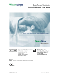
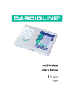
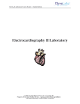
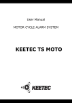
Gorgon G3O3 CONTENTS CONTENTS Delivery set ......................................................................................................................3 Specifications ..................................................................................................................4 Status LED readings......................................................................................................... 4 System control .................................................................................................................5 Remote unit’s buttons designation ...................................................................................5 Batteries replacement.......................................................................................................6 Arming the system ............................................................................................................6 Arming the system with sensors deactivation.....................................................................6 Arming the system with a running engine......................................................................... 6 Rearming the system .......................................................................................................6 Immobilizer........................................................................................................................6 Work of the system in security mode ................................................................................7 Disarming the system........................................................................................................7 Locking/unlocking the doors............................................................................................8 Passenger compartment light activation delay...................................................................8 Car tracing feature............................................................................................................8 “Panic” mode ...................................................................................................................8 Timer channel #1 .............................................................................................................8 Timer channel #2..............................................................................................................8 Distant radio alert channel ...............................................................................................9 System control via a secret code .....................................................................................9 Technical maintenance mode ........................................................................................10 Manual programming of the system................................................................................10 Table of the programmable settings of the system..........................................................11 Description of the programmable settings of the system ................................................12 Level 1 - storing remote control units to the system memory..........................................12 Level 2 - entering a secret code ....................................................................................12 Levels 3 - 7....................................................................................................................12 Level 8 – adjustment of the shock sensor sensitivity ......................................................13 Storage and transportation.............................................................................................13 Warranty .........................................................................................................................14 Acceptance certificate....................................................................................................15 Warranty counterfoils .....................................................................................................15 Technical support: www.gorgon.ru Gorgon G3O3 We thank you for purchasing GORGON G303 car alarm system. Please, read this manual carefully for the sake of proper installation and use. The system is intended to signal about the attempt of unauthorized penetration inside a vehicle or any unlawful physical act in its respect. It is also equipped with a built-in device of engine start-up interlocking. Furthermore, the system offers you a wide range of options to control the auxiliaries such as radio pager, lighting, electric locks of the doors and trunk, window lifters etc. The remote’s radio channel is protected from scanning and interception by the algorithm of dynamic encoding «KEELOQ»® owned by Microchip Technology Inc. USA. The system has got six areas of protection: - along the doors perimeter; - hood and trunk; - ignition; - feeding shut-off; - built-in bi-level shock sensor; - external shock (volume, motion) sensor. When buying this product make sure that the set box is complete, the system operates properly and the warranty counterfoil is filled in correctly. The alarm system is installed stationary on the vehicle and is connected to the regular +12V wiring with the general negative output of accumulator led out to the mass (ground). The system complies with the climatic requirements U-2.1 (N-2.1) according to GOST 15150-69 standard and is intended for the use within the environment temperature range of -40 to +85�С. All the system components should be installed only inside the passenger compartment. Water resistance of the main unit and remote controls complies with the category IP40 according to GOST 14254-96 standard. The system is designed and manufactured in compliance with the State Standard Requirements GOST R 41.97-99, GOST R 50789-95, GOST R 28279-89, GOST 28751-90, GOST 29157-91, GOST R 50607-93. The alarm system GORGON G303 is a sophisticated electronic device and is intended for professional installation only by the authorized dealers. Please make sure that the installation certificate is filled in correctly. Due to the constant improvements in the system construction some slight alterations can take place in our product. They may be not described in this document, but they will not deteriorate the technical characteristics of the product. This product is subject to mandatory certification. DELIVERY SET 1. Main unit..........................................................................1 2. Remote control unit with 3 buttons....................................2 3. Main cable.......................................................................1 4. Limit switch.......................................................................1 5. Cable with a status LED ....................................................1 6. Cable with the “VALET” button ..........................................1 7. Setscrew О4,2х13 ...........................................................2 8. Ground terminal ...............................................................2 9. User’s manual ..................................................................1 10.Installation manual ...........................................................1 11.Siren................................................................................1 12.Package............................................................................1 Gorgon G3O3 INTRODUCTION INTRODUCTION SPECIFICATIONS SPECIFICATIONS Parameter Consumption in security mode, мА �� Main unit supply voltage, V Radio channel frequency��, М�� ��� Hz Frequency deviation��, М�� ��� Hz Emission power��, м�� ��� Wt Operative temperature range Remote control encoding type Max. peak load current , switched in output: - Siren, А � - Warning lights, А � - Interlock circuit, А � - Door locks, � А - Remote radio alert channel, timer channel №3, А � - Timer channel №1, А � - Timer channel №2, А � Remote control buttons qty. Remote control operation range (depends on the battery charge level), м � Shock sensor Dimensions�: - ����������� Main unit��, �� мм - ���������������� Remote control��, мм �� - ��������� Package��, мм �� Electric circuits protection�: - ������������� Feed circuits - ��������������� Output circuits - �������������� Input circuits - �������������� Repolarisation Precious metals content Remote��������� �������� ����� control� feed� Gross weight, not more than, kg Description Not more than� �� 20 9..15 433,92 433,075М������������� Hz����������� ���������� to�������� 434,79� ��� MHz Less than��� 10 –40°С to� ��� +85°С ����� Dynamic� «Keeloq» ��������� ® � 3 7,5+7,5 25 15 0,�3 0,3 0,3 3 30 Built-in, adaptive 9������� 0������ ×9���� 5��� ×�� 29 62������ ×����� 2���� 9×�� 11 140�������� ×1������ 95���� ×��� 105 Fuses Schematic ground� ��������������� fault���������� shielding ��������� Schematic overload/ground fault shielding Schematic repolarization� shielding No А27, 12� V 0,�� 98 NOTE: Dimensions can slightly vary depending on the applied model, but without any negative affect on the declared characteristics. STATUS INDICATOR READINGS Signals of the LED help determine the mode in which the system is in the given moment: • Single short red flashes – the system is armed; • Constantly alight with red – the system is getting ready for automatic arming; • By-turn blinking with red and green – the system is disarmed, but immobilizer is still active; • Not alight – the system is disarmed, immobilizer deactivated or the system is in the technical maintenance mode (with ignition turned on); • Constant dim green light while ignition is active – the system is in the maintenance mode; Gorgon G3O3 SYSTEM CONTROL • Distantly – over the radio channel by means of a three-button remote control unit; • With ignition key; • With “VALET” button; • By the signals of sensors in automatic mode; Button 1 Indicator Button 2 Button 3 REMOTE’S BUTTONS DESIGNATION Button (combination) System is disarmed «1» Silent arming. One signal of the parking lights. «1» → pause not longer than (1,5sec) → «2» Arming with a sonic signal. One signal of the parking lights. «1» → pause not longer than (1,5sec) → «1» Arming with a built-in shock sensor deactivation. Two signals of the parking lights. «1» → pause not longer than (1,5sec) → «3» Arming with an external double-area sensor deactivation. Three signals of the parking lights. «1» → pause not longer than (1,5sec) → «1» + «3»� simultaneously System is armed “Search” (Tracing) mode. Two sonic signals, one signal of the parking lights. Arming with both built-in and external sensors deactivation. Four signals of the parking lights. «2» Silent disarming. Two signals of the parking lights. «2» → pause not longer than (1,5sec) → «2» Disarming with a sonic signal. Two signals of the parking lights. «2» → pause not longer than (1,5sec) → «1» (��������������������� Ignition is switched ��� on�) «1» + «2» ��������� simultaneously «1» + «3» simultaneously «3» Silent arming with ignition turned on. One signal of the parking lights. “Panic” mode – the system continuously produces sonic and light alarm signals. Activate timer channel #1. Activate timer channel #2. In “Panic” mode – press any button to mute siren without the system disarming. Gorgon G3O3 REMOTE’S BATTERIES REPLACEMENT Low battery symptoms are as follow: dimming of the remote’s indicator or decreasing of its operative range. In this case you should replace the battery in the remote control unit. • unscrew the fastening and remove the upper part of the remote’s case; • keeping the PCB on its place, change the battery for a new one (A27 +12V type) observing polarity; • put the upper part of the case back on its place, check the buttons pressing and screw the fastening. ARMING THE SYSTEM The system can be armed either with the ignition turned on or off. With ignition turned off the system can be transferred either to the complete security mode with a control over all available sensors, or to the security mode with one or several sensors deactivation. In both of these modes the system LED signals with a short red flashes. To turn the system to the complete security mode - just press button “1” of the remote control. The system will confirm the performance of command by a single flash of parking lights. To get a sonic confirmation of the command performance – press button “1” again within a 1,5 seconds period. ARMING THE SYSTEM WITH THE SENSORS DEACTIVATION To arm the system with a built-in shock sensor deactivation: press button “1” of the remote unit, release it within a 1,5 seconds period and then press button “2”. The system will produce two signals of the parking lights. To arm the system with an external double-area sensor deactivation: press button “1” of the remote unit, release it within a 1,5 seconds period and then press button “3”. The system will produce three signals of the parking lights. To arm the system with both built-in and external double-area sensors deactivation (perimeter security): press button “1” of the remote unit, release it within a 1,5 seconds period and then press buttons “1”& “3” simultaneously. The system will produce four signals of the parking lights. ARMING THE SYSTEM WITH A RUNNING ENGINE With ignition turned on the system can be transferred to the perimeter protection mode with a running engine. For this purpose press and release remote’s button “1” and then, within a 1,5 seconds period, press and release button “1”. The system will produce one signal of the parking lights. In this case the engine interlock circuit will be DISABLED and the system will automatically deactivate external built-in shock sensor to avoid system response from the engine’s vibration. REARMING THE SYSTEM If within 30 seconds upon the system disarming neither doors nor hood and trunk have been opened, then the system automatically turns to the mode of complete security (if such option was set during programming-sublevel 4.2). During the countdown of this period the LED shines with red light. Each pressing of the button “2” extends for 30 seconds the time left to rearming activation. The system produces two signals of the parking lights, sends command to open the locks and, if it’s allowed by a pre-programmed feature (sublevels 6.1, 6.4), gives command to turn on the pager or timer channel #3. If within a 1,5 seconds period the button “2” is pressed twice the system additionally activates a double signal of siren. IMMOBILIZER If within a 25 seconds period upon opening of a door, hood or trunk the ignition has not been activated, then the system interlocks the engine start-up and turns to the immobilizer mode (if this feature has been assigned during programming – sublevel 4.1). In this mode the LED flashes with red and green lights alternately. Press any button of the remote unit to exit this mode. System’s LED will go down. Gorgon G3O3 WORK OF THE SYSTEM IN SECURITY MODE The main objective of the system in this mode is control over the limit switches and sensors allowed for operations. When a shock or volume sensor’s warning level is activated the system produces a precautionary single sonic & single light signal. The sonic signal can be canceled while programming (sublevel 3.1). The system can also generate a corresponding signal of control over the pager’s transmitter if it is allowed by the programming (sublevels 6.1, 6.3). The system turns to the alarm mode: • if the shock and volume sensors alarm level is activated; • when the hood or trunk is opened; • when the door is opened; • when the ignition is turned on (except for perimeter security mode with a running engine); • after temporal shut-off of the main supply. The light and sonic signals are active in the alarm mode. At the same time sonic signaling can be cancelled on the sublevel 3.2 of programming. Generation of continuous or intermittent sonic signal can be set on sublevel 3.3 of programming. On sublevel 3.4 the duration of alarm signal can be set as 30 or 15 seconds. Besides, the pager’s transmitter is switched on by the system if it is allowed by programming (sublevels 6.1, 6.6). If at the moment of alert activation the system was in the mode of perimeter security with a running engine, then the engine interlock takes place and upon the alert cessation the system turns to the mode of complete security. In other cases the system goes to the previous mode of security. To exit the alarm mode and to stop generating all alert signals – just press any button of the remote control unit. If the warning level of the system’s sensor has been activated three times consequently the system will switch off a corresponding level of the sensor. At the same time, deactivated level of the sensor will be armed once again 15 seconds upon recovery of its operative capacity. Built-in shock sensor. The system disables a warning level of the shock sensor for 15 seconds if after a twofold response of the warning level its alert level was activated. The system disables a warning level of the shock sensor for 15 seconds if it has been in alert mode for three successive times due to response of the shock sensor. DISARMING THE SYSTEM To disarm the system simply press the remote’s button “2”. This will be followed by a double signal of the parking lights. To get a double sonic signal of the system disarming confirmation press the button”2” once again within a 1,5 seconds period. Moreover, during disarming the system provides doors unlocking and generates a respective signal of control over the pager’s transmitter in case it is allowed by programming (sublevels 6.1, 6.4). To disarm the system when it is in alert mode – deactivate this mode first by pressing any button of the remote control. If the alert mode (including the one that was interrupted by a remote’s button pressing) has been activated during the security period, then during disarming the system additionally produces a triple sonic signal and within the same period of time – one continuous signal by the turn lights. The system does not generate any extra signals during disarming if the warning levels of sensors have been activated within the security period. Gorgon G3O3 LOCKING/UNLOCKING OF THE DOORS The system operates the door locks, locking them during arming and unlocking them when disarming the system. Besides, the system is able to lock the doors automatically upon the ignition activation and to unlock them after ignition shut-off, if these operations are allowed by the programming (sublevels 7.2, 7.3). If you need to unlock the doors when ignition is active – shortly press the “VALET” button. COMPARTMENT LIGHT DELAY If the option of the compartment light turning off delay is allowed by the programming (sublevel 3.5) then the system arms door unlocking sensors 15 seconds upon the doors closing. At that the system does not produce any sonic signal if a door was not closed during the system arming. VEHICLE TRACING Pressing of the remote’s button “1” in security mode activates the vehicle tracing function. The system produces a single light and double sonic signal and then returns to the security mode. “PANIC” MODE Regardless of whether the system is armed, armed with a running engine or disarmed, the simultaneous pressing of the remote’s buttons “1” & “2” will activate the “Panic” function - the system produces the light and sonic alarm signals and also sends alarm message to the pager. If the system is disarmed and the engine is running, then turn the system to the perimeter security mode with a running engine to activate the “Panic” mode. That is to say, to activate the “Panic” mode in this case you have to: - press and then release the remote’s button “2”; - press and then release the remote’s button “1”; - press and hold buttons “1” & “2” of the remote control unit simultaneously; - release buttons “1” & “2” upon the “Panic” mode activation; Generation of the sonic signals in “Panic” mode can be cancelled by programming (sublevel 3.2). Moreover, a message transmitting to the pager can be allowed by the programming (sublevel 6.6). Press any button of the remote unit to exit “Panic” mode. The system turns to the security mode even if it was disarmed at the moment of the “Panic” mode activation. TIMER CHANNEL #1 Timer channel #1 is designed to perform one extra option, subject to your choice. Algorithm of this channel is set during the system programming (level 5). The channel can be activated during arming, disarming and by simultaneous pressing of the buttons “1” & “3” of the remote control. Duration of the signal on the timer channel #1 is set during programming. During the time of the timer channel #1 work as well as within 10 seconds upon its cessation, the system does not respond to the status of the shock and volume sensors. You can apply the channel #1 for one of the following purposes: - dim light turning on during the arming; - the compartment timed lighting during the disarming; TIMER CHANNEL #2 ТTimer channel is designed to control the work of the hood or trunk lock. The channel is activated by the remote’s button “3”. Signal duration appearing on the channel #2 is 1 second. If the channel #2 has been activated during security mode then, during the time of its work and within the 10 seconds upon its cessation the system, still staying armed, does not respond to the status of the shock sensor and the limit switch of the hood or trunk. If within this period of time neither hood nor trunk Gorgon G3O3 has been opened, the system arms temporally deactivated switches again. But if the hood or trunk were opened the system will wait until they are closed and then will start a new 10 seconds countdown. DISTANT RADIO ALERT CHANNEL The system has the channel of control over the pager’s radio transmitter and can generate the following control signals: - arming signal; - disarming signal; - signal of control over the pager’s radio channel; - warning signal (activation of the shock or volume sensor’s warning level); - alarm signal; Generation of each of these signals can be allowed or prohibited during the system programming (sublevels 6.1 – 6.6). Radio channel control signal is sent 4 minutes upon the system arming. Signal duration is 5 seconds. If the system has been transferred to the alarm mode before the radio channel control signal was generated then there will be no control over the pager’s radio channel. The system does not control the status of shock and volume sensors during radio channel control signal generation. The radio alert channel can be reassigned to the timer channel #3 (sublevel 6.1). In this mode the signal of the timer channel #3 can be generated in the following cases: - during disarming (sublevel 6.4); - during arming (sublevel 6.5); - in alarm situation (sublevel 6.6); The duration of the timer channel signal is set by sublevel 6.7. SYSTEM CONTROL OVER A SECRET CODE If the remote unit is not available or damaged the system can be operated by entering of a secret code. When entering a secret code you have an option to switch between the following system modes: - from armed or alert modes to disarmed mode; - from immobilizer turned on to immobilizer turned off; - from disarming with ignition turned off to the mode of system programming. In case of loss or failure of the available remotes this feature allows you to record and use new remote units. To enter a secret code (two digits from 1 to 16 set on the second level of programming) you have to do the following: - shortly press the “VALET” button the number of times equal to the first digit of a secret code. Each pressing of the button is reported by a green flash of the LED. The intervals between button pressings should not exceed 1 second; - when the code’s first digit is entered make an interval until a red flash appears on the system LED thus reporting reception of the code’s first digit; - immediately after this enter the second digit of a secret code by pressing shortly the “VALET” button the required number of times with intervals not longer than 1 second. At this again each pressing will be followed by a green flash of the LED; - if you have entered the code correctly the LED is blinking for 2 seconds by-turn with red and green lights, whereupon the necessary switching of the system mode is performed. - if you have failed to enter a correct code the system will return to the mode in which it used to be before your attempt to enter a secret code. TECHNICAL MAINTENANCE MODE This mode is designed for placing a vehicle to the technical maintenance service. In this mode the vehicle is disarmed and automatic arming, immobilizer door locks controls are disabled. To turn the car to this mode: - disarm a car (see “Disarming the System” clause); Gorgon G3O3 - turn the ignition on; - press and hold the “VALET” button for at least 3 seconds; - press the remote’s button “2”; - release the “VALET” button. The transfer of the system to the maintenance mode will be reported a by dim green light of the LED with ignition turned on. With ignition turned off the LED will be put out. To exit this mode simply press any button of the remote control unit. MANUAL PROGRAMMING OF THE SYSTEM Some of the system’s settings can be adjusted in a service (secondary) mode of programming. Eight levels of programming are envisaged by the system, each of them having several sublevels. The sublevels are denoted by a combination of two digits the first of which corresponds to the number of a level and the second one to the number of a sublevel. There are two methods to enter the mode of programming. Method one: - disarm a car (see “Disarming the System” clause); - open and the close the door; - with the engine turned off press and hold the button “VALET”. The LED must light with green. - holding the “VALET” button, press the remote’s button “2”; - release button “VALET”. Alternative: - enter a secret code (see “System Control Over a Secret Code”); The transfer of the system to the mode of programming is reported by frequent LED red and green flashes whereupon the indicator goes down. Press the “VALET” button a corresponding number of times to choose the required level of programming. The interval between the pressings should not exceed 1 second. Each pressing is reported by a green flash of the LED. Upon accomplishment of code dialing the system will confirm the entered number by the LED’s red flashes. Then the LED produces a green flash; this corresponds to the first sublevel on a chosen level, and after this the light is set according to the current meaning on the given sublevel. On most of sublevels the setting allows or prohibits the performance of a certain function. At this a green LED’s lights means that the given function is allowed and the red light means that it is prohibited. The setting can be changed by remote’s buttons pressing: button “1” allows performance of the function, button “2” – prohibits. During pressing the “VALET” button and holding it until frequent LED’s red and green flashes the system stores a current setting to its memory and proceeds to the next sublevel of a chosen level. LED will indicate the number of a new sublevel by green flashes whereupon its light will be set in accordance with its current meaning. If this didn’t happen and the LED turned off, then it means that all sublevels have been used and the system is waiting for entering of the number of a new level. To exit this mode at any sublevel simply turn the ignition on. 10 Gorgon G3O3 TABLE OF PROGRAMMABLE SETTINGS OF THE SYSTEM Indicator Level name Level & sublevel Storing remotes 1. By-turn recording (up to 3 units) to the system’s memory Entering a 2. Entering a new secret code secret code 3.1 Signal at the warning level of sensors 3.2 Signal in “Alert” & “Panic” modes Work of siren 3.3 Signal choice 3.4 Signal duration 3.5 Compartment light switch-off delay Immobilizer activation after Immobilizer’s 4.1 disarming functions & automatic 4.2 Automatic rearming arming Work of the timer channel #1 5.1 Timer channel activation during arming 5.2 Timer channel activation during disarming 5.3 Timer channel on/off by the remote’s buttons “1” + “3” 5.4 Timer channel work duration (max. 40 minutes) 6.1 Work of the radio alert channel 6.2 Control over the channel Work of the distant radio alert channel (timer channel #3) Door locks control 6.3 Alert (warning) message transmission 6.4 Channel activation when disarming GREEN See description See description PROHIBITED ALLOWED PROHIBITED ALLOWED INTERMITTENT CONTINUOUS 30 seconds 15 seconds PROHIBITED ALLOWED PROHIBITED ALLOWED PROHIBITED ALLOWED PROHIBITED ALLOWED PROHIBITED ALLOWED PROHIBITED ALLOWED 1 second PROHIBITED ALLOWED PROHIBITED ALLOWED PROHIBITED ALLOWED PROHIBITED ALLOWED 6.5 Channel activation when arming PROHIBITED ALLOWED 6.6 Channel activation in alert mode PROHIBITED ALLOWED 6.7 Radio alert channel work duration (max. 40 minutes) 7.1 Door locks control signal duration 5 seconds 0,8 seconds 7.2 Doors locking when ignition is on PROHIBITED ALLOWED 7.3 Doors unlocking when ignition is off 7.4 Doors sensor polarity PROHIBITED ALLOWED NEGATIVE POSITIVE NEGATIVE POSITIVE 7.5 Trunk sensor polarity Shock sensor sensitivity RED 1 second 8.1 Warning level adjustment See description 8.2 Alert level adjustment See description Factory settings are marked with grey background Gorgon G3O3 11 DESCRIPTION OF THE PROGAMMABLE SETTINGS OF THE SYSTEM LEVEL 1 – storing the remote units to the system’s memory. The system is capable to keep in memory the codes of three remote control units – one at each of the sublevels. Every time it is necessary to record the codes of all the remote units that will be used later on. If one remote unit is in use then its code must be recorded three times (at each of the sublevels). When two units are in use the code of one of them must be recorded twice. If a remote unit is lost the codes of the remaining units must be recorded anew in order to erase from their memory the code of the lost one. Sublevel 1.1 - recording the first remote unit LED shines with red light. Press and release any button of the remote control, the LED keeps on shining with red. Press any button of the remote unit once again. Frequent red and green flashes correspond to a successful storing of the first unit to the system’s memory. After that the system automatically goes on to the next sublevel of the first level. Sublevel 1.2 - recording the second remote unit The second unit is stored to the memory of the system the same way as the first one. Sublevel 1.3 – recording the third remote unit The third unit is stored to the memory of the system the same way as the first one. Upon completion of recording the LED goes down and the system is waiting for a new level entry. LEVEL 2 – entering a secret code. Secret code, composed of two digits from 1 to 16, provides control over the system when the remote unit is not available (see “System Control over a Secret Code” clause). Factory setting of a secret code is «1 – 1». CAUTION! Remember and write your secret code down and keep it some place outside the vehicle. You won’t be able to control the system and to change its settings without the remote control unit. Change the preset secret code for the safety sake before you start using the system. Sublevel 2.1 The LED is not alight. Enter the first digit of a secret code by entering the “VALET” button consequently with the required number of times with the interval not more than 1 second. The system will repeat the entered number by the LED’s green flashes. Enter the second digit in the same manner as the first one and the system will also reproduce it. Upon completion of both digits entering the LED will be shining with a dim green light – this means that the system is waiting for repeated code entering for the purpose of its comparison and confirmation. Repeat the code entering by the “VALET” button with an interval between the first and the second digits of approx. 2 seconds. If the code does not coincide with the one that has been inserted before, the LED will produce a red signal on the background of a dim green light. For a new attempt press and hold the “VALET” button until the LED stops flashing. If the second entering is correct the system will report acceptance with frequent red and green flashes. After that, the LED goes down and the system is waiting for a new level number entering. My personal secret code is: - LEVELS 3 -7 LED status: green- work is allowed, red- work is prohibited. Settings change: remote’s button “1” – to allow, button “2” – to prohibit. “VALET” button pressing: to store the current setting and go to the next sublevel. Sublevels 5.4, 6.7- timer duration setting The LED shines with red light. Press and hold the “VALET” (the LED will shine with green light) for a period equal to the required by the timer duration. During the “VALET” button releasing the timer work duration is captured, the system confirms a successful recording by frequent red and green lights of the LED, whereupon the LED goes down and the system is waiting for a new level number entry. Timer work duration range: 1 second to 40 minutes. Turn the ignition on if you don’t want to change the sublevel settings. 12 Gorgon G3O3 LEVEL 8 – Shock sensor sensitivity adjustment. Sublevel 8.1 - adjustment of a built-in shock sensor’s operation threshold by a warning level. During the sensor’s threshold of sensitivity adjustment the LED blinks with red and green light. At this, the higher the sensor’s sensitivity, the more green light is available on the LED. All in all, the sensor has got 256 gradations of sensitivity. Each pressing of the remote’s button “1” decreases sensitivity per one gradation; each pressing of the button “2” increases it. At the up most sensitivity level the system produces a triple sonic signal while the LED goes down. At the low-level of sensitivity that corresponds to this level deactivation the system also produces a triple sonic signal while the LED is shining with red light. During the adjustment an actual sensitivity of the sensor can be verified. At that, the sensor’s triggering will be followed by a single signal of the siren. At the “VALET” button pressing the system stores a current setting and goes to the next level. Sublevel 8.2 - adjustment of a built-in shock sensor’s operation threshold by alert level. This adjustment is identical to the setting described in Sublevel 8.1. At the “VALET” button pressing the system stores a current setting and is waiting for a new level number entry. At the moment of sensitivity adjustment the main block (unit) with a built-in shock sensor should be already installed and fixed in the vehicle to provide precision of adjustment. Do not set a very high level of sensitivity otherwise it may cause false triggering of the system. STORAGE AND TRANSPORTATION The alarm systems, packed according to the required norms, should be stored at the environmental temperature of 1 to 400 C at relative humidity of 80% (rated at 250 C). The indoor air must not contain acidity or alkali vapors which cause corrosion. Warranty shelf life is 6 months. The alarm system packed in shipper container can be transported by motor or railway transport in house cars or containers as well as by air or water transport in waterproof isothermal compartments or holds for any distance and at any speed. Transportation should be performed in accordance with the regulations and rules applicable to the respective type of transport. All the warning writings on the package should be strictly followed during loading and transportation. Gorgon G3O3 13 WARRANTY The manufacturer guarantees correspondence of the alarm system to the Technical Requirements with the observance of operating conditions, installation, storage, transportation, stipulated in the given manual. The item should pass the Quality Control department of the manufacturer. The item should be used only in accordance with operation and installation manual. The item is subject to qualified professional installation with the authorized service centers. The fitter of the system must fill in the certificate of installation, enclosed to the set box. The malfunctioned during the warranty period through the fault of the manufacturer composite devices of the system are subject to replacement or repair by the fitter (manufacturer or a company, accomplishing complex maintenance). The consumer is deprived of the right to the after-sales service in the following cases: • upon the warranty period expiry; • in case of the violation of the rules of installation, operation, transportation and storage; • in case of the presence of the mechanical damages of the external components of the system appeared after the moment of sale, including the fire impact, breakdown, penetration of the aggressive liquids and water, misconduct; • in case of the presence of the damages caused by improper setting or adjustment; • in case of the system’s composite devices replacement for those which are not recommended by the manufacturer; • if the factory sealing is broken; • in case of the duly filled in installation certificate or the warranty counterfoil absence; Warranty operation life is 1 year from the date of sale, but not longer than 1,5 years since the moment of manufacture. This warranty does not apply to the batteries of remote control units, which have a natural limited service life. Repair and maintenance of the system with an expired warranty period should be performed for the account of consumer according to the separate agreements between the supplier/fitter and the consumer. Resolutions of the manufacturer (fitter) in respect of the questions, connected with the claims are final. The defective parts which have been replaced are the property of the manufacturer (fitter). 14 Gorgon G3O3 CERTIFICATE OF ACCEPTANCE The car alarm system GORGON G303 corresponds to the Technical Requirements TU 4372-004-55684712-2005 and is found suitable for operation. Factory number _______________________________________________ Date of manufacture ____________________________________________ Signatures of the responsible for acceptance Seal Packer _______________________________________________________ Signature (personal stamp) WARRANTY COUNTERFOIL Item model GORGON G303 Factory number ________________________________________________ Date of purchase «____» ______________________ 200___. _____________________________________________________________ Stamp of the trading enterprise (maintenance/fitting centre) Signature of sales person _______________________________________________ ____ CERTIFICATE OF INSTALLATION I, undersigned ___________________________________________ the professional fitter, verify that the installation of the car alarm system, described below, was performed by myself according to the installation instructions provided by the system manufacturer. Vehicle description: Model __________________________________________________________ Type ____________________________________________________________ VIN _____________________________________________________________ Registration number ________________________________________________ Description of the vehicle alarm system Model GORGON G303 Name of organization, address and fitter’s seal ________________________________________________________________ ________________________________________________________________ ________________________________________________________________ Signature ________________________ ____________________________ Accepted by______________________ ____________________________ Gorgon G3O3 15 16 Made in Russia Gorgon G3O3