1
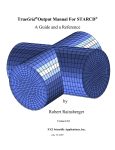
TrueGrid®Output Manual For KIVA4
A Guide and a Reference
by
David J. Torres and Robert Rainsberger
Version 2.3.0
XYZ Scientific Applications, Inc.
February 1, 2007
Copyright © 2007 by XYZ Scientific Applications, Inc. All rights reserved.
TrueGrid,® the TrueGrid® Output Manual for KIVA4, and related products of XYZ Scientific Applications, Inc. are
copyrighted and distributed under license agreements. Under copyright laws, they may not be copied in whole or in part
without prior written approval from XYZ Scientific Applications, Inc. The license agreements further restrict use and
redistribution.
XYZ Scientific Applications, Inc. makes no warranty regarding its products or their use, and reserves the right to change its
products without notice. This manual is for informational purposes only, and does not represent a commitment by XYZ
Scientific Applications, Inc. XYZ Scientific Applications, Inc. accepts no responsibility or liability for any errors or
inaccuracies in this document or any of its products.
TrueGrid ®is a registered trademark of XYZ Scientific Applications, Inc.
Some other product names appearing in this book may also be trademarks or registered trademarks of their trademark holders.
Copyright © 2007 by XYZ Scientific Applications, Inc. All Rights Reserved
ii
February 1, 2007
TrueGrid® Output Manual For KIVA4
Table of Contents
Table of Contents . . . . . . . . . . . . . . . . . . . . . . . . . . . . . . . . . . . . . . . . . . . . . . . . . . . . . . . . . . . . . 3
I. Introduction . . . . . . . . . . . . . . . . . . . . . . . . . . . . . . . . . . . . . . . . . . . . . . . . . . . . . . . . . . . . . . . 5
II. KIVA4 Output Guide . . . . . . . . . . . . . . . . . . . . . . . . . . . . . . . . . . . . . . . . . . . . . . . . . . . . . 11
III. Example Problem 1 . . . . . . . . . . . . . . . . . . . . . . . . . . . . . . . . . . . . . . . . . . . . . . . . . . . . . . . 13
IV. Example Problem 2 . . . . . . . . . . . . . . . . . . . . . . . . . . . . . . . . . . . . . . . . . . . . . . . . . . . . . . . 31
V. KIVA4 Output Reference . . . . . . . . . . . . . . . . . . . . . . . . . . . . . . . . . . . . . . . . . . . . . . . . . . 35
kivabc
KIVA4 Boundary Condition (Part Phase) . . . . . . . . . . . . 35
kivabci
KIVA4 Boundary Condition (Part Phase) . . . . . . . . . . . . 35
kivabc
KIVA4 Boundary Condition (Merge Phase) . . . . . . . . . . 36
co kivabc
KIVA4 Boundary Conditions Display (Merge Phase) . . . 37
VI. INDEX . . . . . . . . . . . . . . . . . . . . . . . . . . . . . . . . . . . . . . . . . . . . . . . . . . . . . . . . . . . . . . . . . 39
Copyright © 2007 by XYZ Scientific Applications, Inc. All Rights Reserved
TrueGrid® Output Manual For KIVA4
February 1, 2007
3
Copyright © 2007 by XYZ Scientific Applications, Inc. All Rights Reserved
4
February 1, 2007
TrueGrid® Output Manual For KIVA4
I. Introduction
KIVA-4 is an engine simulation code which accommodates unstructured grids. KIVA-4 does impose
restrictions on the unstructured grid if the snapping routines are used. The snapping routines allow
layers of cells within the piston to be added or removed and layers of cells to alternately assume a
role of solid valve surfaces. If the snapping routines are used, the mesh must be vertically layered
in the cylinder. Specifically a vertical column of cells in the cylinder must be composed of only
hexahedra or only prisms if the mesh is to be snapped. KIVA-4 assumes all elements (including
tetrahedra, prisms and pyramids) are logically equivalent to a hexahedra. Figure 1 shows the node
ordering for a hexahedral cell. One can create non-hexahedral cells by degenerating nodes. Figures
2-4 show how nodes can be degenerated in KIVA-4 to create other types of elements.
Figure 1 Node ordering for hexahedral cell
Copyright © 2007 by XYZ Scientific Applications, Inc. All Rights Reserved
TrueGrid® Output Manual For KIVA4
February 1, 2007
5
Figure 2 Node ordering for a prism cell. The left face
has been collapsed to an edge.
Figure 3 Possible node ordering for pyramid cell.
Copyright © 2007 by XYZ Scientific Applications, Inc. All Rights Reserved
6
February 1, 2007
TrueGrid® Output Manual For KIVA4
Figure 4 Possible node ordering for tetrahedral cell.
KIVA-4’s mesh format requires one to define cell types and face types. Figure 5 shows the face
conventions used for a cell in KIVA-4. Each face of a cell needs to be defined with a face type.
Figure 6 shows the cell types that would be defined in a typical engine mesh. Figure 7 shows the
corresponding exterior faces types that would be defined. Interior face types would be defined to be
fluid.
Copyright © 2007 by XYZ Scientific Applications, Inc. All Rights Reserved
TrueGrid® Output Manual For KIVA4
February 1, 2007
7
Figure 5 Face conventions in KIVA-4 for a cell.
Figure 6 Cell types in a typical engine mesh.
Copyright © 2007 by XYZ Scientific Applications, Inc. All Rights Reserved
8
February 1, 2007
TrueGrid® Output Manual For KIVA4
Figure 7 Face types in a typical engine mesh. The boundary between
the bowl and the squish region should be a fluid boundary but the
walls of the bowl should be moving boundaries.
KIVA-4 uses the following cell types with their numerical values in parenthesis:
squish (10):
flbowl (11):
fldome (14):
flfluid (20,30,40,50):
Cells in the cylinder region should be of squish type.
Cells in a piston bowl should be of flbowl type.
A separate dome region can be created, if desired.
Cells in ports should be identified as flfluid cells. The exact value of
flfluid to be used depends on the port ordering (the first port should
have cells with type 20, the second port should have cells with type
30, etc.).
KIVA-4 uses the following face types with their respective numerical values in parenthesis:
moving (10,11,12,13,14, ...): For faces that reside on a moving surface (e.g. piston crown, bowl
faces, top and bottom of valves).
solid (20):
For faces that reside on a solid non-moving surface (e.g. cylinder
walls, port walls). The sides of valves are considered solid surface
despite the fact that they move.
Copyright © 2007 by XYZ Scientific Applications, Inc. All Rights Reserved
TrueGrid® Output Manual For KIVA4
February 1, 2007
9
solidh(21):
axis(30):
fluid(40):
periodf(50):
periodd(60):
inflow(70):
outflow(80):
presin(90):
presout(100):
For faces that reside on the top or head of the cylinder. These surfaces
can be labeled solid if the piston does not move. However if the
piston does move, the faces should be labeled solidh surfaces.
For faces that coincide with an axis. The axis faces are only used in
2D or 3D sector geometries. These faces are actually edges because
they are faces of hexahedra that have been collapsed to a line
segment.
For any non-periodic face through which fluid can freely pass.
For faces on the front periodic boundary of a mesh.
For faces on the derriere periodic boundary of a mesh.
For faces on an inflow boundary.
For faces on a continuative outflow boundary.
For cell faces on a pressure inflow boundary.
For faces on a pressure outflow boundary.
The mesh file name in KIVA-4 is called kiva4grid. The input deck is called itape5. Valve
movement can be specified using a file called itape18.
Copyright © 2007 by XYZ Scientific Applications, Inc. All Rights Reserved
10
February 1, 2007
TrueGrid® Output Manual For KIVA4
II. KIVA4 Output Guide
The kiva command selects the KIVA4 output option. It can be issued in the control or merge phase.
In the merge phase, use the write command to write the kiva4grid file. Be sure to merge the nodes
using one of the merging commands such as stp before you write the output file. This is the standard
procedure in TrueGrid®.
There are a few special considerations required when building a KIVA4 model. There are no
material properties to specify. However, the mt, mti, and mate commands are used to assign
predefined materials to the mesh. The following material numbers can be used:
1
2
10
11
14
20
30
40
50
for squish (TrueGrid® default)
for inactive
for squish
for bowl
for dome
for port 1
for port 2
for port 3
for port 4
Use the kivabc or the kivabci commands in the part phase or the kivabc command in the merge
phase to set face types, except for periodic conditions. The default interior face type is fluid. The
default exterior face type is solid.
Care is needed in assigning the axis boundary condition. The edge that is placed on the axis must
be a degenerate face. From outward appearances, this will be an edge of a wedge element. However,
the internal representation of the wedge is be a hex element with 6 faces. When building the part that
falls on the axis, use the computation window to select the degenerate face. Then use the kivabc
command to assign the axis boundary condition to this face.
The Block Boundary (bb) and the Transitional Block Boundary (trbb) commands have the periodf
(for the front of a periodic boundary condition) and the periodd (for the derriere of a periodic
boundary condition) options. The periodic boundary condition cannot be set using the kivabc
command. The bb and trbb commands with these options accomplishes 3 things.
1. When an appropriate coordinate transformation is applied either to the master or the slave side
of the block boundary, the nodal coordinates of the slave side are forced to be periodic with the
master side.
2. This command, using the periodf and periodh options, produce the periodic boundary condition.
Copyright © 2007 by XYZ Scientific Applications, Inc. All Rights Reserved
TrueGrid® Output Manual For KIVA4
February 1, 2007
11
3. The same options also produce the node-to-node correspondence for the periodic constraints. The
nodes of a master block boundary interface will appear first in the list of paired periodic vertices.
You can generate prisms, tetrahedrons, and pyramid elements by attaching some nodes of an element
to other nodes of the same element. This is the way to create what is referred to in TrueGrid® as
degenerate hexahedral elements. Only prism (or wedge) elements are allowed on the axis of a
periodic boundary condition. All four types are allowed elsewhere in the mesh. Only the axis
boundary condition has meaning on a degenerate face and only if it degenerates to an edge. Some
of these conditions are due to the requirement that the periodf and periodd faces, when found on
a single element, must be on opposing faces.
If precision is an issue, you may need to use the double precision version of TrueGrid®. This can
become an issue with periodic boundaries because the slave side (derriere) must be exactly the
master side (front) when the inverse periodic transformation is applied to the slave side. The single
precision version of TrueGrid® may produce errors in the last digit.
Copyright © 2007 by XYZ Scientific Applications, Inc. All Rights Reserved
12
February 1, 2007
TrueGrid® Output Manual For KIVA4
III. Example Problem 1
This is a simple example of a piston with 2 valves. When creating a model, Figures 8-12 can
help in designing the mesh. Figures 8-10 show the cell types used, and Figures 11-12 show the
face types used in the mesh. Figure 7 is also helpful in determining what face types should be
used.
Figure 8 Cell types used for 2-valve engine mesh. The cylinder region is designated squish
(10), the first port and runner are designated flfluid (20) and the second port and runner are
designated (30).
Copyright © 2007 by XYZ Scientific Applications, Inc. All Rights Reserved
TrueGrid® Output Manual For KIVA4
February 1, 2007
13
Figure 9 Cross-section view of cell types used in 2-valve engine mesh.
Copyright © 2007 by XYZ Scientific Applications, Inc. All Rights Reserved
14
February 1, 2007
TrueGrid® Output Manual For KIVA4
Figure 10 Top view of cell types in 2-valve engine mesh. Note the use of O-grids in the
valve and cylinder perimeters.
Copyright © 2007 by XYZ Scientific Applications, Inc. All Rights Reserved
TrueGrid® Output Manual For KIVA4
February 1, 2007
15
Figure 11 Cross -section view of face types for the first valve.
Note that the valve and the valve stem are solid.
Figure 12 Cross-section view of face types for the second
valve. Note that the edges of the valve and the valve stem are
solid.
Copyright © 2007 by XYZ Scientific Applications, Inc. All Rights Reserved
16
February 1, 2007
TrueGrid® Output Manual For KIVA4
The problem is broken into 6 parts. Parts 1 and 3 form
the stem. The part is extended through the entire
model and the material below the extent of the stem is
set to squish. The other parts are built around the stem
parts.
Figure 13 Stem parts
The valve heads and the fluid around them are formed
by parts 2 and 4. The cores are missing because they
are formed by parts 1 and 3. Transitions are used for
increase the mesh density out from the stem as the
radius increases.
Figure 14 Valve head parts
Copyright © 2007 by XYZ Scientific Applications, Inc. All Rights Reserved
TrueGrid® Output Manual For KIVA4
February 1, 2007
17
Part 5 forms the two ports that connect to the fluid
around the valve ports. To assure that these parts
match, nod for node, block boundary interfaces were
formed.
Figure 15 Port parts
The last part is the bulk of cylinder around parts 1-5.
Care was taken to form a topology that gave a nearly
perfect o-grid at the outer radius while giving a nearly
orthogonal mesh around the two ports. The elliptic
smoothing was used extensively for this effect.
Figure 16 Cylinder part
Copyright © 2007 by XYZ Scientific Applications, Inc. All Rights Reserved
18
February 1, 2007
TrueGrid® Output Manual For KIVA4
Figure 17 Fully merged parts
Copyright © 2007 by XYZ Scientific Applications, Inc. All Rights Reserved
TrueGrid® Output Manual For KIVA4
February 1, 2007
19
Figure 18 Final mesh with temperature contours in computational simulation with KIVA-4.
The final mesh contains 129,768 nodes and 124096 hex elements. The model is parametric, so both
shape and size are easily adjusted.
Copyright © 2007 by XYZ Scientific Applications, Inc. All Rights Reserved
20
February 1, 2007
TrueGrid® Output Manual For KIVA4
The following is the resulting session file with comments inserted to help the reader. The TrueGrid®
User’s Manual for a full discussion on generating a mesh. These commands are included to
demonstrate a complete model for KIVA4.
title TrueGrid test problem for KIVA4
c Choose KIVA4 as the output format
kiva
c Simplify the part commands since there are no shells
intyp 2
parameter
r1 1 c radius of the valve stem
r2 5 c radius of the port
r3 7 c radius of the valve head
r4 30 c radius of the cylinder
d1 12 c offset from center of the valve
d2 8 c width of the inlet/outlet
d3 1 c thickness of the valve head
d4 9 c depth of valve 1
d5 12 c depth of valve 2
d6 .4 c thickness of first transition region
z1 50 c hieght of cylinder
z2 60 c hieght of bottom of inlet/outlet
z3 68 c hieght of top of inlet/outlet
r5 [sqrt(%d1*%d1+%r3*%r3+2*%d1*%r3/sqrt(2))]
;
c Surfaces needed to form the mesh
sd 1 cy 0 0 0 0 0 1 %r4 c cylinder wall
sd 2 cy [-%d1] 0 0 0 0 1 %r1 c valve stem port 1
sd 3 cy [-%d1] 0 0 0 0 1 %r2 c port 1
sd 4 cy [-%d1] 0 0 0 0 1 %r3 c valve head port 1
sd 5 cy %d1 0 0 0 0 1 %r1 c valve stem port 2
sd 6 cy %d1 0 0 0 0 1 %r2 c port 2
sd 7 cy %d1 0 0 0 0 1 %r3 c valve head port 2
sd 8 plan 0 [-%d2/2] 0 0 1 0 c back face of inlet/outlet
sd 9 plan 0 [%d2/2] 0 0 1 0 c front face of inlet/outlet
sd 10 plan 0 0 0 0 0 1 c bottom of cylinder
sd 11 plan 0 0 %z1 0 0 1 c top of cylinder
sd 12 plan 0 0 %z2 0 0 1 c bottom of inlet/outlet
Copyright © 2007 by XYZ Scientific Applications, Inc. All Rights Reserved
TrueGrid® Output Manual For KIVA4
February 1, 2007
21
sd 13 plan 0 0 %z3 0 0 1 c top of inlet/outlet
sd 14 plan 0 0 [%z1-%d4] 0 0 1 c depth of top face of valve 1
sd 15 plan 0 0 [%z1-%d4-%d3] 0 0 1 c depth of bottom of valve 1
sd 16 plan 0 0 [%z1-%d5] 0 0 1 c depth of top face of valve 2
sd 17 plan 0 0 [%z1-%d5-%d3] 0 0 1 c depth of bottom of valve 2
sd 18 cy 0 0 0 0 0 1 %r5
sd 19 cy [-%d1] 0 0 0 0 1 [(%r2+%r3)/2] c construction port 1
sd 20 cy %d1 0 0 0 0 1 [(%r2+%r3)/2] c construction port 2
sd 21 cy [-%d1] 0 0 0 0 1 [%r1+%d6] c valve stem port 1
sd 22 cy %d1 0 0 0 0 1 [%r1+%d6] c valve stem port 2
c Valve stem 1
block 1 2 5 6;
1 2 5 6;
1 51 61 69;
[-%r1/3-%d1] [-%r1/3-%d1] [%r1/3-%d1] [%r1/3-%d1]
[-%r1/3] [-%r1/3] [%r1/3] [%r1/3]
0 %z1 %z2 %z3
c Delete the corners of the butterfly topology
dei 1 2 0 3 4;1 2 0 3 4;;
c Project to the cylinder
sfi -1 -4;-1 -4;;sd 2
c Save the interfaces
bb 2 1 1 3 1 4 1;
bb 4 2 1 4 3 4 2;
bb 2 4 1 3 4 4 3;
bb 1 2 1 1 3 4 4;
c Insert additional partitions to connect to the port
insprt 1 5 2 9
insprt 1 5 2 1
c Project to the cylinders
sfi ;; -2;sd 15
sfi ;; -3;sd 14
c Assign material numbers
mt 1 1 2 0 0 6 2 c valve stem inactive
mt 1 1 1 0 0 2 10 c fluid below valve stem
Copyright © 2007 by XYZ Scientific Applications, Inc. All Rights Reserved
22
February 1, 2007
TrueGrid® Output Manual For KIVA4
c Glue the exposed faces together for smoothing
bb 1 2 1 2 2 6 40; bb 2 1 1 2 2 6 40;
bb 3 1 1 3 2 6 41; bb 3 2 1 4 2 6 41;
bb 3 3 1 4 3 6 42; bb 3 3 1 3 4 6 42;
bb 2 3 1 2 4 6 43; bb 1 3 1 2 3 6 43;
c Smoothe the mesh
unifm 1 2 1 4 3 1 & 2 3 1 3 4 1 & 2 1 1 3 2 1 20 0.001 1 ;
unifm 1 2 2 4 3 2 & 2 3 2 3 4 2 & 2 1 2 3 2 2 20 0.001 1 ;
unifm 1 2 3 4 3 3 & 2 3 3 3 4 3 & 2 1 3 3 2 3 20 0.001 1 ;
unifm 1 2 4 4 3 4 & 2 3 4 3 4 4 & 2 1 4 3 2 4 20 0.001 1 ;
unifm 1 2 5 4 3 5 & 2 3 5 3 4 5 & 2 1 5 3 2 5 20 0.001 1 ;
unifm 1 2 6 4 3 6 & 2 3 6 3 4 6 & 2 1 6 3 2 6 20 0.001 1 ;
c Assign non-default boundary conditions
kivabci -1 -4;-1 -4;3 -6;solid
kivabc 1 1 2 4 4 2 movingb1
endpart
c Valve 1
block 1 3 8 9 18 19 24 26;
1 3 8 9 18 19 24 26;
1 51 61 69;
[-%r1/3-%d1] [-%r1/3-%d1] [-%r1/3-%d1] [-%r1/3-%d1]
[%r1/3-%d1] [%r1/3-%d1] [%r1/3-%d1][%r1/3-%d1]
[-%r1/3][-%r1/3] [-%r1/3] [-%r1/3]
[%r1/3] [%r1/3] [%r1/3] [%r1/3]
0 %z1 %z2 %z3
c Delete regions to form a butterfly topology
dei 1 4 0 5 8;1 4 0 5 8;;
dei 4 5;4 5;;
c Nodal distributions for smoother mesh
res 2 4 1 3 5 4 i .85
res 6 4 1 7 5 4 i [1/.85]
res 4 2 1 5 3 4 j .85
res 4 6 1 5 7 4 j [1/.85]
c Project to surfaces
sfi -1 -8;-1 -8;;sd 4
Copyright © 2007 by XYZ Scientific Applications, Inc. All Rights Reserved
TrueGrid® Output Manual For KIVA4
February 1, 2007
23
sfi -2 -7;-2 -7;;sd 3
sfi -3 -6;-3 -6;;sd 21
c Transition from a coarse mesh in the stem
trbb 4 4 1 5 4 4 1;
trbb 5 4 1 5 5 4 2;
trbb 4 5 1 5 5 4 3;
trbb 4 4 1 4 5 4 4;
c Save interfaces
bb 4 1 1 5 1 2 5;
bb 8 4 1 8 5 2 6;
bb 4 8 1 5 8 2 7;
bb 1 4 1 1 5 2 8;
c Insert partitions
insprt 1 4 4 1
insprt 1 4 5 7
c Project
sfi -1; -6; 3 4;sd 9
sfi -1; -5; 3 4;sd 8
c Save interface
bb 1 5 3 1 6 4 30;
c More inserted partitions
insprt 1 5 2 9
insprt 1 5 2 1
c More projections
sfi ;; -2;sd 15
sfi ;; -3;sd 14
c Assign material numbers
mt 1 1 2 0 0 3 2
mt 1 1 4 0 0 6 20
mt 1 1 1 0 0 2 10
mt 1 1 3 0 0 4 10
c Assign boundary conditions
kivabc 1 1 2 8 10 2 movingb1
Copyright © 2007 by XYZ Scientific Applications, Inc. All Rights Reserved
24
February 1, 2007
TrueGrid® Output Manual For KIVA4
kivabc 1 1 3 8 10 3 movingt1
kivabci -1 -8;-1 -10;2 3;solid
endpart
c Valve stem 2
block 1 2 5 6;
1 2 5 6;
1 51 61 69;
[-%r1/3+%d1] [-%r1/3+%d1] [%r1/3+%d1] [%r1/3+%d1]
[-%r1/3] [-%r1/3] [%r1/3] [%r1/3]
0 %z1 %z2 %z3
c Delete the corners of the butterfly topology
dei 1 2 0 3 4;1 2 0 3 4;;
c Project to the cylinder
sfi -1 -4;-1 -4;;sd 5
c Save the interfaces
bb 2 1 1 3 1 4 11;
bb 4 2 1 4 3 4 12;
bb 2 4 1 3 4 4 13;
bb 1 2 1 1 3 4 14;
c Insert additional partitions to connect to the port
insprt 1 5 2 12
insprt 1 5 2 1
c Project to the cylinders
sfi ;; -2;sd 17
sfi ;; -3;sd 16
c Assign material numbers
mt 1 1 2 0 0 6 2
mt 1 1 1 0 0 2 10
c Glue the exposed faces together for smoothing
bb 1 2 1 2 2 6 44;bb 2 1 1 2 2 6 44;
bb 3 1 1 3 2 6 45;bb 3 2 1 4 2 6 45;
bb 3 3 1 4 3 6 46;bb 3 3 1 3 4 6 46;
bb 2 3 1 2 4 6 47;bb 1 3 1 2 3 6 47;
Copyright © 2007 by XYZ Scientific Applications, Inc. All Rights Reserved
TrueGrid® Output Manual For KIVA4
February 1, 2007
25
c Smoothe the mesh
unifm 1 2 1 4 3 1 & 2 3 1 3 4 1 & 2 1 1 3 2 1 20 0.001 1 ;
unifm 1 2 2 4 3 2 & 2 3 2 3 4 2 & 2 1 2 3 2 2 20 0.001 1 ;
unifm 1 2 3 4 3 3 & 2 3 3 3 4 3 & 2 1 3 3 2 3 20 0.001 1 ;
unifm 1 2 4 4 3 4 & 2 3 4 3 4 4 & 2 1 4 3 2 4 20 0.001 1 ;
unifm 1 2 5 4 3 5 & 2 3 5 3 4 5 & 2 1 5 3 2 5 20 0.001 1 ;
unifm 1 2 6 4 3 6 & 2 3 6 3 4 6 & 2 1 6 3 2 6 20 0.001 1 ;
c Assign non-default boundary conditions
kivabci -1 -4;-1 -4;3 -6;solid
kivabc 1 1 2 4 4 2 movingb2
endpart
c Valve 2
block 1 3 8 9 18 19 24 26;
1 3 8 9 18 19 24 26;
1 51 61 69;
[-%r1/3+%d1] [-%r1/3+%d1] [-%r1/3+%d1] [-%r1/3+%d1]
[%r1/3+%d1] [%r1/3+%d1] [%r1/3+%d1][%r1/3+%d1]
[-%r1/3][-%r1/3] [-%r1/3] [-%r1/3]
[%r1/3] [%r1/3] [%r1/3] [%r1/3]
0 %z1 %z2 %z3
c Delete regions to form a butterfly topology
dei 1 4 0 5 8;1 4 0 5 8;;
dei 4 5;4 5;;
c Nodal distributions for smoother mesh
res 2 4 1 3 5 4 i .85
res 6 4 1 7 5 4 i [1/.85]
res 4 2 1 5 3 4 j .85
res 4 6 1 5 7 4 j [1/.85]
c Project to surfaces
sfi -1 -8;-1 -8;;sd 7
sfi -2 -7;-2 -7;;sd 6
sfi -3 -6;-3 -6;;sd 22
c Transition from a coarse mesh in the stem
trbb 4 4 1 5 4 4 11;
trbb 5 4 1 5 5 4 12;
Copyright © 2007 by XYZ Scientific Applications, Inc. All Rights Reserved
26
February 1, 2007
TrueGrid® Output Manual For KIVA4
trbb 4 5 1 5 5 4 13;
trbb 4 4 1 4 5 4 14;
c Save interfaces
bb 4 1 1 5 1 2 15;
bb 8 4 1 8 5 2 16;
bb 4 8 1 5 8 2 17;
bb 1 4 1 1 5 2 18;
c Insert partitions
insprt 1 4 4 1
insprt 1 4 5 7
c Project
sfi -8; -6; 3 4;sd 9
sfi -8; -5; 3 4;sd 8
c Save interface
bb 8 5 3 8 6 4 31;
c More inserted partitions
insprt 1 5 2 12
insprt 1 5 2 1
c More projections
sfi ;; -2;sd 17
sfi ;; -3;sd 16
c Assign material numbers
mt 1 1 2 0 0 3 2
mt 1 1 4 0 0 6 30
mt 1 1 1 0 0 2 10
mt 1 1 3 0 0 4 10
c Assign boundary conditions
kivabc 1 1 2 8 10 2 movingb2
kivabc 1 1 3 8 10 3 movingt2
kivabci -1 -8;-1 -10;2 3;solid
endpart
c inlet/outlet
Copyright © 2007 by XYZ Scientific Applications, Inc. All Rights Reserved
TrueGrid® Output Manual For KIVA4
February 1, 2007
27
block 1 21 0 22 42;
1 8;
1 9;
[-1.5*%r4] [-%d1-%r3] 0 [%d1+%r3] [1.5*%r4]
[-%d2/2] [%d2/2]
%z2 %z3
c Save interfaces
bb 2 1 1 2 2 2 30;
bb 4 1 1 4 2 2 31;
c Assign material numbers
mt 1 1 1 2 2 2 20
mt 4 1 1 5 2 2 30
c Assign boundary conditions
kivabc 1 1 1 1 2 2 presin
kivabc 5 1 1 5 2 2 presout
endpart
c Main cylinder
block 1 3 12 21 30 32;
1 3 12 14 23 25 34 36;
1 51;
[-%r4] [-%r5] [-%d1+%r3] [%d1-%r3] %r5 %r4
[-%r4] [-%r5] [-%d1] [-%r3] %r3 %d1 %r5 %r4
0 %z1
c Add elements
mseq i 5 0 9 0 5
mseq j 5 0 5 0 5 0 5
c Delete blocks to form a butterfly topology
dei 1 3 0 4 6; 1 3 0 6 8;;
dei 2 3 0 4 5; 4 5;;
c Move some of the key vertices inti position
pb 3 5 1 3 5 2 xy [-%d1+%r3*cos(45)] [%r3*sin(45)]
pb 1 6 1 3 8 2 xy [-%d1+%r3*cos(45)] [%r3*sin(45)+5]
pb 4 5 1 4 5 2 xy [%d1-%r3*cos(45)] [%r3*sin(45)]
pb 4 6 1 6 8 2 xy [%d1-%r3*cos(45)] [%r3*sin(45)+5]
Copyright © 2007 by XYZ Scientific Applications, Inc. All Rights Reserved
28
February 1, 2007
TrueGrid® Output Manual For KIVA4
pb 3 4 1 3 4 2 xy [-%d1+%r3*cos(45)] [-%r3*sin(45)]
pb 1 1 1 3 3 2 xy [-%d1+%r3*cos(45)] [-%r3*sin(45)-5]
pb 4 4 1 4 4 2 xy [%d1-%r3*cos(45)] [-%r3*sin(45)]
pb 4 1 1 6 3 2 xy [%d1-%r3*cos(45)] [-%r3*sin(45)-5]
c Node distribution other than equal spacing for smoothness
res 6 3 1 6 6 2 j 1
res 1 3 1 1 6 2 j 1
res 1 3 1 2 6 2 i .85
res 3 1 1 4 2 2 j .85
res 3 7 1 4 8 2 j [1/.85]
res 5 3 1 6 6 2 i [1/.85]
c Project
sfi -1 -6; -1 -8;;sd 1
sfi -2 -5; -2 0 3 4 0 5 6 0 -7; 1 2;sd 18
c Glue to saved interfaces
bb 2 4 1 2 5 2 8;
bb 2 5 1 3 5 2 7;
bb 3 4 1 3 5 2 6;
bb 2 4 1 3 4 2 5;
bb 4 4 1 4 5 2 18;
bb 4 5 1 5 5 2 17;
bb 5 4 1 5 5 2 16;
bb 4 4 1 5 4 2 15;
c Glue the exposed faces together for smoothing
bb 1 3 1 3 3 2 60; bb 3 1 1 3 3 2 60;
bb 4 1 1 4 3 2 61; bb 4 3 1 6 3 2 61;
bb 4 6 1 6 6 2 62; bb 4 6 1 4 8 2 62;
bb 3 6 1 3 8 2 63; bb 1 6 1 3 6 2 63;
c Smooth the mesh
unifm 2 5 1 5 6 1 & 2 3 1 5 4 1 &
3 6 1 4 7 1 & 3 4 1 4 5 1 & 3 2 1 4 3 1 50 0 1 ;
unifm 2 5 2 5 6 2 & 2 3 2 5 4 2 &
3 6 2 4 7 2 & 3 4 2 4 5 2 & 3 2 2 4 3 2 50 0 1 ;
c Assign a material number to this part
mate 10
Copyright © 2007 by XYZ Scientific Applications, Inc. All Rights Reserved
TrueGrid® Output Manual For KIVA4
February 1, 2007
29
endpart
c Enter the merge phase
merge
c Merge the nodes
stp .01
Copyright © 2007 by XYZ Scientific Applications, Inc. All Rights Reserved
30
February 1, 2007
TrueGrid® Output Manual For KIVA4
IV. Example Problem 2
This example has a periodic boundary condition with elements on the axis. When creating a
model, it is best to have a diagram (Figure 19) shown below. Figure 20 shows vertical velocities
computed with KIVA-4 in a compression-expansion calculation.
Figure 19 Face types used in periodic sector mesh. All cells would be
designated squish (100.
Copyright © 2007 by XYZ Scientific Applications, Inc. All Rights Reserved
TrueGrid® Output Manual For KIVA4
February 1, 2007
31
Figure 20 Vertical velocity computed with KIVA-4 in
compression-expansion calculation
Copyright © 2007 by XYZ Scientific Applications, Inc. All Rights Reserved
32
February 1, 2007
TrueGrid® Output Manual For KIVA4
Periodic Mesh Construction with TrueGrid®
The following is the resulting session file with comments inserted to help the reader. The TrueGrid®
User’s Manual for a full discussion on generating a mesh. These commands are included to
demonstrate a complete model for KIVA4.
title KIVA 4 test problem using periodic conditions
c First part is one element thick and on the axis
cylinder 1 2;1 2;1 21;0 .5;0 60;0 10;
c Create the periodic boundary condition
bb 1 1 1 2 1 2 1 periodf ; ;
bb 1 2 1 2 2 2 1 periodd rz -60;;
c Identify face for transition to next part
bb 2 1 1 2 2 2 2;
c Set the material to squish
mate 10
c Set the boundary
kivabc 1 1 1 1 2 2
kivabc 1 1 2 2 2 2
kivabc 1 1 1 2 2 1
conditions
axis
solidh
moving
endpart
Figure 21 Transitions
c Second part will be attached to the first
with more elements
cylinder 1 4;1 4;1 21;.5 2;0 60;0 10;
c Transition from the first part
trbb 1 1 1 1 2 2 2;
c Transition to the third part
bb 2 1 1 2 2 2 3;
c Periodic boundary condition
bb 1 1 1 2 1 2 4 periodf ; ;
bb 1 2 1 2 2 2 4 periodd rz -60 ; ;
c Squish material
mate 10
Copyright © 2007 by XYZ Scientific Applications, Inc. All Rights Reserved
TrueGrid® Output Manual For KIVA4
February 1, 2007
33
c Set the boundary conditions
kivabc 1 1 1 2 2 1 moving
kivabc 1 1 2 2 2 2 solidh
endpart
c Third part like the second part with more elements
cylinder 1 7;1 10;1 21;2 5;0 60;0 10;
c Geometric increase in element size in radial direction
res 1 1 1 2 2 2 i 1.075
c Transition from second part
trbb 1 1 1 1 2 2 3;
c Periodic boundary condition
bb 1 1 1 2 1 2 5 periodf ; ;
bb 1 2 1 2 2 2 5 periodd rz -60 ; ;
c Squish material
mate 10
c Set the boundary
kivabc 1 1 1 2 2 1
kivabc 1 1 2 2 2 2
kivabc 2 1 1 2 2 2
conditions
moving
solidh
solid
Figure 22 Merged parts
endpart
merge
c Merge the nodes
stp .001
c Write the output file
kiva
write
To view any of the boundary conditions, except axis, use the
co command. For example, you can view the solidh boundary
condition on this problem with the following command:
co kivabc solidh
Figure 23 Boundary conditions
Copyright © 2007 by XYZ Scientific Applications, Inc. All Rights Reserved
34
February 1, 2007
TrueGrid® Output Manual For KIVA4
V. KIVA4 Output Reference
The syntax and remarks for the KIVA4 specific commands can be found below.
kivabc
KIVA4 Boundary Condition for a Region (Part Phase)
kivabc region type
where type can be
moving
movingb1
movingt1
movingb2
movingt2
movingb3
movingt3
movingb4
movingt4
solid
solidh
axis
fluid
inflow
outflow
presin
presout
for moving piston
for moving bottom face of 1st valve
for moving top face of 1st valve
for moving bottom face of 2nd valve
for moving top face of 2nd valve
for moving bottom face of 3rd valve
for moving top face of 3rd valve
for moving bottom face of 4th valve
for moving top face of 4th valve
for a face of a solid
for a solid face of a cylinder head
for a face on the axis
for a fluid face (default)
for an inlet
for an outlet
for pressure inflow
for pressure outflow
Remarks
An interior face can be assigned a boundary condition. Since an interior face can be found on to
elements, it is possible to assign different boundary conditions to the same face. This would be
flagged as an error. Use the bb or trbb command to assign periodic boundary conditions.
kivabci
KIVA4 Boundary Condition for a Progression (Part Phase)
kivabci progression type
where type can be
moving
movingb1
movingt1
movingb2
for moving piston
for moving bottom face of 1st valve
for moving top face of 1st valve
for moving bottom face of 2nd valve
Copyright © 2007 by XYZ Scientific Applications, Inc. All Rights Reserved
TrueGrid® Output Manual For KIVA4
February 1, 2007
35
movingt2
movingb3
movingt3
movingb4
movingt4
solid
solidh
axis
fluid
inflow
outflow
presin
presout
for moving top face of 2nd valve
for moving bottom face of 3rd valve
for moving top face of 3rd valve
for moving bottom face of 4th valve
for moving top face of 4th valve
for a face of a solid
for a solid face of a cylinder head
for a face on the axis
for a fluid face (default)
for an inlet
for an outlet
for pressure inflow
for pressure outflow
Remarks
An interior face can be assigned a boundary condition. Since an interior face can be found on to
elements, it is possible to assign different boundary conditions to the same face. This would be
flagged as an error. Use the bb or trbb command to assign periodic boundary conditions.
kivabc
KIVA4 Boundary Condition (Merge Phase)
kivabc fset set_name type
where type can be
moving for moving piston
movingb1
for moving bottom face of 1st valve
movingt1
for moving top face of 1st valve
movingb2
for moving bottom face of 2nd valve
movingt2
for moving top face of 2nd valve
movingb3
for moving bottom face of 3rd valve
movingt3
for moving top face of 3rd valve
movingb4
for moving bottom face of 4th valve
movingt4
for moving top face of 4th valve
solid
for a face of a solid
solidh
for a solid face of a cylinder head
axis
for a face on the axis
fluid
for a fluid face (default)
inflow
for an inlet
outflow
for an outlet
presin
for pressure inflow
presout
for pressure outflow
Copyright © 2007 by XYZ Scientific Applications, Inc. All Rights Reserved
36
February 1, 2007
TrueGrid® Output Manual For KIVA4
Remarks
An interior face can be assigned a boundary condition. Since an interior face can be found on to
elements, it is possible to assign different boundary conditions to the same face. This would be
flagged as an error. Use the bb or trbb command to assign periodic boundary conditions.
co kivabc
KIVA4 Boundary Conditions Display (Merge Phase)
co kivabc type
where type can be
moving
movingb1
movingt1
movingb2
movingt2
movingb3
movingt3
movingb4
movingt4
solid
solidh
axis
fluid
periodf
periodd
inflow
outflow
presin
presout
for moving piston
for moving bottom face of 1st valve
for moving top face of 1st valve
for moving bottom face of 2nd valve
for moving top face of 2nd valve
for moving bottom face of 3rd valve
for moving top face of 3rd valve
for moving bottom face of 4th valve
for moving top face of 4th valve
for a face of a solid
for a solid face of a cylinder head
for a face on the axis
for a fluid face (default)
for the periodic front
for the periodic derriere
for an inlet
for an outlet
for pressure inflow
for pressure outflow
Remarks
The co command has many other options. For a complete list see the TrueGrid® User’s Manual. An
axis cannot be displayed at this time.
Copyright © 2007 by XYZ Scientific Applications, Inc. All Rights Reserved
TrueGrid® Output Manual For KIVA4
February 1, 2007
37
Copyright © 2007 by XYZ Scientific Applications, Inc. All Rights Reserved
38
February 1, 2007
TrueGrid® Output Manual For KIVA4
VI. INDEX
adding layers . . . . . . . . . . . . . . . . . . . . . . . . 5
axis . . . . . . . . . . . . . . . . . . . . . . . 10-12, 31, 35
bb . . . . . . . . . . . . . . . . . . . . . . . . . . . . . 11, 35
block boundaries . . . . . . . . . . . . . . . . . . . . 11
bottom . . . . . . . . . . . . . . . . . . . . . . . . . . . . . 7
boundary conditions . . . . . . . . . . . . . . . . . . 35
bowl . . . . . . . . . . . . . . . . . . . . . . . . . . . . 8, 11
cell types . . . . . . . . . . . . . . . . . . . . . . . . . . . 7
co kivabc . . . . . . . . . . . . . . . . . . . . . . . . . . 37
coordinate transformation . . . . . . . . . . . . . 11
defaults . . . . . . . . . . . . . . . . . . . . . . . . . . . . 11
degenerate edge . . . . . . . . . . . . . . . . . . . . . 12
degenerate face . . . . . . . . . . . . . . . . . . . 11, 12
degenerating nodes . . . . . . . . . . . . . . . . . . . . 5
derriere . . . . . . . . . . . . . . . . . . . . . . . . . . . . . 7
derriere periodic . . . . . . . . . . . . . . . . . . . . . 31
dome . . . . . . . . . . . . . . . . . . . . . . . . . . . . . . 11
element types . . . . . . . . . . . . . . . . . . . . . . . . 5
exterior . . . . . . . . . . . . . . . . . . . . . . . . . . . . . 7
face conventions . . . . . . . . . . . . . . . . . . . . . . 7
face types . . . . . . . . . . . . . . . . . . . . . . . . . . . 7
file name . . . . . . . . . . . . . . . . . . . . . . . . . . . 10
flbowl . . . . . . . . . . . . . . . . . . . . . . . . . . . . . . 9
fldome . . . . . . . . . . . . . . . . . . . . . . . . . . . . . 9
flfluid . . . . . . . . . . . . . . . . . . . . . . . . . . . 9, 13
fluid . . . . . . . . . . . . . . . . . . . . . . . . . . . 10, 35
front . . . . . . . . . . . . . . . . . . . . . . . . . . . . . . . 7
front periodic . . . . . . . . . . . . . . . . . . . . . . . 31
hexahedra . . . . . . . . . . . . . . . . . . . . . . . . 5, 12
inactive . . . . . . . . . . . . . . . . . . . . . . . . . . . . 11
inflow . . . . . . . . . . . . . . . . . . . . . . . . . . 10, 35
input deck . . . . . . . . . . . . . . . . . . . . . . . . . . 10
interior . . . . . . . . . . . . . . . . . . . . . . . . . . . . . 7
itape18 . . . . . . . . . . . . . . . . . . . . . . . . . . . . 10
itape5 . . . . . . . . . . . . . . . . . . . . . . . . . . . . . 10
kiva . . . . . . . . . . . . . . . . . . . . . . . . . . . . . . . 11
kiva4grid . . . . . . . . . . . . . . . . . . . . . . . 10, 11
kivabc . . . . . . . . . . . . . . . . . . . . . . . 11, 35, 36
kivabci . . . . . . . . . . . . . . . . . . . . . . . . . 11, 35
layers . . . . . . . . . . . . . . . . . . . . . . . . . . . . . . 5
left . . . . . . . . . . . . . . . . . . . . . . . . . . . . . . . . 7
master side . . . . . . . . . . . . . . . . . . . . . . . . . 11
mate . . . . . . . . . . . . . . . . . . . . . . . . . . . . . . 11
materials . . . . . . . . . . . . . . . . . . . . . . . . . . . 11
merge nodes . . . . . . . . . . . . . . . . . . . . . . . . 11
moving . . . . . . . . . . . . . . . . . . . . . . . 9, 31, 35
movingb1 . . . . . . . . . . . . . . . . . . . . . . . . . . 35
movingb2 . . . . . . . . . . . . . . . . . . . . . . . . . . 35
movingb3 . . . . . . . . . . . . . . . . . . . . . . . . . . 35
movingb4 . . . . . . . . . . . . . . . . . . . . . . . . . . 35
movingt1 . . . . . . . . . . . . . . . . . . . . . . . . . . 35
movingt2 . . . . . . . . . . . . . . . . . . . . . . . . . . 35
movingt3 . . . . . . . . . . . . . . . . . . . . . . . . . . 35
movingt4 . . . . . . . . . . . . . . . . . . . . . . . . . . 35
mt . . . . . . . . . . . . . . . . . . . . . . . . . . . . . . . . 11
mti . . . . . . . . . . . . . . . . . . . . . . . . . . . . . . . 11
O-grids . . . . . . . . . . . . . . . . . . . . . . . . . . . . 14
opposing faces . . . . . . . . . . . . . . . . . . . . . . 12
ourput file . . . . . . . . . . . . . . . . . . . . . . . . . . 11
outflow . . . . . . . . . . . . . . . . . . . . . . . . . 10, 35
periodd . . . . . . . . . . . . . . . . . . . . . . . . . 10, 11
periodf . . . . . . . . . . . . . . . . . . . . . . . . . 10, 11
periodh . . . . . . . . . . . . . . . . . . . . . . . . . . . . 11
periodic . . . . . . . . . . . . . . . . . . . . . . . . 31, 35
port . . . . . . . . . . . . . . . . . . . . . . . . . . . . 11, 13
precision . . . . . . . . . . . . . . . . . . . . . . . . . . . 12
presin . . . . . . . . . . . . . . . . . . . . . . . . . . 10, 35
presout . . . . . . . . . . . . . . . . . . . . . . . . . 10, 35
prism . . . . . . . . . . . . . . . . . . . . . . . . . . . . . 12
prisms . . . . . . . . . . . . . . . . . . . . . . . . . . . . . . 5
pyramid . . . . . . . . . . . . . . . . . . . . . . . . . 5, 12
removing layers . . . . . . . . . . . . . . . . . . . . . . 5
restrictions . . . . . . . . . . . . . . . . . . . . . . . . . . 5
right . . . . . . . . . . . . . . . . . . . . . . . . . . . . . . . 7
runner . . . . . . . . . . . . . . . . . . . . . . . . . . . . . 13
slave side . . . . . . . . . . . . . . . . . . . . . . . . . . 11
snapping routines . . . . . . . . . . . . . . . . . . . . . 5
solid . . . . . . . . . . . . . . . . . . . . . . . . . 9, 31, 35
solidh . . . . . . . . . . . . . . . . . . . . . . . 10, 31, 35
squish . . . . . . . . . . . . . . . . . . . 8, 9, 11, 13, 31
stp . . . . . . . . . . . . . . . . . . . . . . . . . . . . . . . . 11
temperatures . . . . . . . . . . . . . . . . . . . . . . . . 19
Copyright © 2007 by XYZ Scientific Applications, Inc. All Rights Reserved
TrueGrid® Output Manual For KIVA4
February 1, 2007
39
tetrahedra . . . . . . . . . . . . . . . . . . . . . . . . 5, 12
top . . . . . . . . . . . . . . . . . . . . . . . . . . . . . . . . 7
transitions . . . . . . . . . . . . . . . . . . . . . . . . . . 11
trbb . . . . . . . . . . . . . . . . . . . . . . . . . . . . 11, 35
unstructured . . . . . . . . . . . . . . . . . . . . . . . . . 5
valve movement . . . . . . . . . . . . . . . . . . . . . 10
velocities . . . . . . . . . . . . . . . . . . . . . . . . . . 31
vertically layered . . . . . . . . . . . . . . . . . . . . . 5
wedge . . . . . . . . . . . . . . . . . . . . . . . . . . . . . 11
write . . . . . . . . . . . . . . . . . . . . . . . . . . . . . . 11
Copyright © 2007 by XYZ Scientific Applications, Inc. All Rights Reserved
40
February 1, 2007
TrueGrid® Output Manual For KIVA4