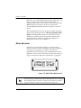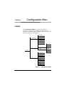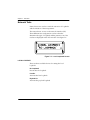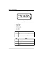
1
ESU LT
User Manual
Part Number 1200410L1
Document Number 61200410L1-1A
June 1999
901 Explorer Boulevard
P.O. Box 140000
Huntsville, AL 35814-4000
Phone: (256) 963-8000
© 1999 ADTRAN, Inc.
All rights reserved.
Printed in USA.
ADTRAN Year 2000 (Y2K) Readiness Disclosure
ADTRAN has established a Year 2000 program to ensure that our products will
correctly function in the new millennium. ADTRAN warrants that all products
meet Y2K specifications regardless of model or revision.
Information about ADTRAN’s Y2K compliance program is available at the following locations:
ADTRAN Web Site
www.adtran.com
Product Matrix
www.adtran.com/y2kfax.html
Faxback Document
Line
(256) 963-8200
Y2K plans and product certifications are
listed in the matrix.
Y2K Project Line
(256) 963-2200
E-mail
[email protected]
iii
Federal Communications Commission Radio Frequency Interference
Statement:
This equipment has been tested and found to comply with the limits for a Class
B digital device, pursuant to Part 15 of the FCC Rules. These limits are designed
to provide reasonable protection against harmful interference when the equipment is operated in a commercial environment. This equipment generates, uses,
and can radiate radio frequency energy and, if not installed and used in accordance with the instruction manual, may cause harmful interference to radio frequencies. Operation of this equipment in a residential area is likely to cause
harmful interference, in which case the user will be required to correct the interference at his own expense.
Shielded cables must be used with this unit to ensure compliance with Class B
FCC limits.
Changes or modifications to this unit not expressly approved by
the party responsible for compliance could void the user’s authority to operate the equipment.
Canadian Class B Products
The following information must be placed on the label and in the user’s manual
for all Class B products shipped into Canada.
This Class B digital apparatus meets all requirements of the Canadian Interference Equipment Regulations.
Cet appareil numerique dela class B respecte les exigences du Reglement sur le
Materiel Brouilleur du Canada.
iv
IMPORTANT SAFETY INSTRUCTIONS
When using your telephone equipment, please follow these
basic safety precautions to reduce the risk of fire, electrical
shock, or personal injury:
1
Do not use this product near water, such as near a bath
tub, wash bowl, kitchen sink, laundry tub, in a wet basement, or near a swimming pool.
2
Avoid using a telephone (other than a cordless-type) during an electrical storm. There is a remote risk of shock
from lightning.
3
Do not use the telephone to report a gas leak in the vicinity of the leak.
4
Use only the power cord, power supply, and/or batteries
indicated in the manual. Do not dispose of batteries in a
fire. They may explode. Check with local codes for special disposal instructions.
SAVE THESE INSTRUCTIONS
v
International Cordset Selection
The following list is a selection of recommended cordset configurations to
ensure protective earthing continuity when utilizing this product internationally. This list gives the proper rating, cordage type, and plug/connector configuration for the specific country where the product is to be utilized.
Country
Mimimum
Cordage Type
Rating
250 VAC, 10A
HAR
Plug Type
CEE 7/7
Connector
Type
IEC 60320 C13
Australia, China
Denmark
India/South Africa
Israel
Italy
Japan
250 VAC, 10A
250 VAC, 10A
250 VAC, 10A
250 VAC, 10A
250 VAC, 10A
125 VAC, 7 A
AS 3112
Afsnit 107-2-D1
BS 546
SI-32
CEI-23-16/VII
JIS 8303
IEC 60320 C13
IEC 60320 C13
IEC 60320 C13
IEC 60320 C13
IEC 60320 C13
IEC 60320 C13
Russian Federation
Switzerland
Ireland, United
Kingdom
Korea
North America
250 VAC, 10A
250 VAC, 10A
250 VAC, 10A
V76419
HAR
HAR
HAR
HAR
12-1367
Yukita 300 V
HAR
HAR
HAR
GOST 7396
SEV 1011
BS 1363
IEC 60320 C13
IEC 60320 C13
IEC 60320 C13
125 VAC, 10A
125 VAC, 10A
HAR
AWG
KSC 8305
NEMA 5-15
IEC 60320 C13
IEC 60320 C13
Austria
Belgium
Czech Republic
Finland
France
Germany
Greece
Hungary
Iceland
Luxembourg
Netherlands
Norway
Poland
Portugal
Slovenia
Spain
Sweden
Yugoslavia
vi
Warranty and Customer Service
ADTRAN will replace or repair this product within five years from the date of
shipment if the product does not meet its published specifications or if it fails
while in service. For detailed warranty, repair, and return information, see the
ADTRAN Equipment Warranty and Repair and Return Policy Procedure.
Return Material Authorization (RMA) is required prior to returning equipment
to ADTRAN.
For Service, RMA requests, or more information, contact one of the numbers
found at the inside back page of this manual.
vii
viii
Table of Contents
List of Figures ............................................................................................................ xv
List of Tables ...........................................................................................................xvii
Chapter 1. Introduction ..........................................................................................1-1
ESU LT Overview .....................................................................................................1-1
Functional Description ......................................................................................1-1
ESU LT Rear Panel .............................................................................................1-2
ESU LT Features ................................................................................................1-3
ESU LT Interfaces ...............................................................................................1-3
Network Interface (NI) .............................................................................. 1-4
Network Test Interface .............................................................................. 1-4
Nx56/64 Serial Interface ........................................................................... 1-4
Control Port Input ......................................................................................1-4
Chain Port Output ..................................................................................... 1-4
Software Management.......................................................................................1-4
Front Panel ..................................................................................................1-4
T-Watch Pro Management Software Program ....................................... 1-5
ESU LT Testing ...................................................................................................1-5
Self-test ........................................................................................................1-5
Loopback Tests ...........................................................................................1-6
Network Loopbacks ........................................................................... 1-6
Payload Loopback .............................................................................. 1-6
DTE Interface Loopbacks ..........................................................................1-7
DTE Loopback ..................................................................................... 1-7
Pattern Generation .............................................................................................1-8
Bridge/Router Application .............................................................................. 1-9
Chapter 2. Installation ............................................................................................2-1
Inspecting for Shipping Damages ......................................................................... 2-1
Items Shipped by ADTRAN ............................................................................. 2-1
Items Provided by Customer............................................................................ 2-1
Power Connection..............................................................................................2-2
61200410L1-1
ESU LT User Manual
ix
Table of Contents
Power Up Testing and Initialization ...............................................................2-2
Chapter 3. Operation...............................................................................................3-1
Operation ...................................................................................................................3-1
General Menu Operation ..................................................................................3-1
Menu Structure ...................................................................................................3-2
Four Opening Menu Functions ................................................................3-3
STATUS .......................................................................................................3-3
NI PERF RPTS (REPORTS) ................................................................3-3
CURR ERR/ALM ................................................................................3-3
ERR/ALM HIST ..................................................................................3-3
CONFIG .......................................................................................................3-3
NETWORK (NI) ..................................................................................3-3
UNIT .....................................................................................................3-3
PORT .....................................................................................................3-3
UTIL .............................................................................................................3-3
TIME/DATE ........................................................................................3-4
SOFTWARE REV ................................................................................3-4
REINIT UNIT .......................................................................................3-4
ADDRESS .............................................................................................3-4
SET PASSCODE ..................................................................................3-4
KEYPAD ...............................................................................................3-4
FACT RESTORE ..................................................................................3-4
TEST .............................................................................................................3-4
NETWORK TESTS ..............................................................................3-4
RUN SELF TEST ..................................................................................3-4
PORT TESTS ........................................................................................3-5
CANCEL TESTS ..................................................................................3-5
Menu Features ....................................................................................................3-5
Data Field ....................................................................................................3-5
Display Field ...............................................................................................3-5
Arrows .........................................................................................................3-5
Example Menu Operations .......................................................................3-5
To select a menu item... ......................................................................3-5
To select a submenu item ...................................................................3-6
To Set the Data Field ...........................................................................3-7
To View Display-Only Data Fields ...................................................3-7
To Exit Any Menu Field Operation or Display .............................. 3-7
Front Panel ..........................................................................................................3-8
Chapter 4. Status Menu ..........................................................................................4-1
STATUS ......................................................................................................................4-1
x
ESU LT User Manual
61200410L1-1
Table of Contents
NI PERF RPTS.....................................................................................................4-2
Reset Perf CNTRS ...............................................................................4-2
%AS .......................................................................................................4-2
%EF .......................................................................................................4-2
ES ...........................................................................................................4-2
BES ........................................................................................................4-2
SES .........................................................................................................4-3
DM ........................................................................................................4-3
UAS .......................................................................................................4-3
CURR ERR/ALM ...............................................................................................4-3
Alarms and Errors ......................................................................................4-4
LOSS OF SIGNAL ...............................................................................4-4
LOSS OF FRAME ................................................................................ 4-4
LOSS OF TS16 MF ...............................................................................4-4
LOSS OF CRC-4 .................................................................................. 4-4
AIS RECEIVED ....................................................................................4-4
TS16 AIS RCV ................................................................................... 4-4
REMOTE ALARM .............................................................................. 4-4
REMOTE MF ALARM ....................................................................... 4-4
EXT CLOCK ALARM ........................................................................4-4
BPV/CV RCVD ................................................................................... 4-4
FAS WORD ERROR ........................................................................... 4-5
E-BIT ERROR .......................................................................................4-5
PLL ALARM ........................................................................................4-5
ERR/ALM Hist...................................................................................................4-5
Chapter 5. Configuration Menu ........................................................................... 5-1
CONFIG .....................................................................................................................5-1
Network (NI) ......................................................................................................5-2
INTERFACE ................................................................................................5-2
FRAMING ...................................................................................................5-3
CCS ........................................................................................................5-3
CAS/TS16 ............................................................................................5-3
UNFRAMED ........................................................................................5-3
LINE CODE ...............................................................................................5-4
CRC-4 ...........................................................................................................5-4
NFAS WORD ..............................................................................................5-4
RFA GEN .....................................................................................................5-4
TIMING MODE ..........................................................................................5-4
Network Timing .................................................................................. 5-5
Internal Timing ................................................................................... 5-5
DTE Timing .........................................................................................5-6
61200410L1-1
ESU LT User Manual
xi
Table of Contents
Unit .......................................................................................................................5-6
CNTRL PORT .............................................................................................5-7
POSITION ............................................................................................5-7
MODEM INIT ......................................................................................5-7
DATA RATE ........................................................................................5-7
ALARMS .....................................................................................................5-8
TRAPS ...................................................................................................5-8
OUTPUT ...............................................................................................5-8
TEL NUM .............................................................................................5-8
Port Config (Port Configuration) .....................................................................5-9
INTERFACE .........................................................................................5-9
TS0 RATE .............................................................................................5-9
MAPPING ............................................................................................5-9
DTE TX CLOCK ..................................................................................5-9
START TS0 .........................................................................................5-10
NUMBER OF TS0s ............................................................................5-10
DATA ..................................................................................................5-10
CTS ......................................................................................................5-10
DCD ....................................................................................................5-10
DSR ......................................................................................................5-10
INBAND .............................................................................................5-11
Chapter 6. Utility Menu..........................................................................................6-1
UTIL ............................................................................................................................6-1
Time/Date ...........................................................................................................6-2
Software Rev ......................................................................................................6-3
Reinit Unit ...........................................................................................................6-3
Address ................................................................................................................6-3
Set Passcode ........................................................................................................6-3
Keypad .................................................................................................................6-4
Fact Restore .........................................................................................................6-4
Chapter 7. Test Menu..............................................................................................7-1
TEST ............................................................................................................................7-1
Network Tests .....................................................................................................7-2
LOCAL LOOPBCK ....................................................................................7-2
No Loopback ........................................................................................7-2
Line On .................................................................................................7-2
Payload On ...........................................................................................7-2
REMOTE LOOPBCK .................................................................................7-3
No Loopback ........................................................................................7-3
FE1 Loopback ......................................................................................7-3
xii
ESU LT User Manual
61200410L1-1
Table of Contents
TEST PATTERN .........................................................................................7-3
1:8 ALL TS0s ........................................................................................7-3
QRSS ACT TS0s ................................................................................... 7-3
511 Active TS0s ................................................................................... 7-3
All Zeros ...............................................................................................7-3
All Ones ................................................................................................7-3
CLR ERRORS ..............................................................................................7-4
INSERT QRSS or 511 ERRORS ................................................................. 7-4
Run Self-test ........................................................................................................7-5
Port Tests .............................................................................................................7-6
Cancel Tests.........................................................................................................7-6
Chapter 8. Example Operations ............................................................................ 8-1
Testing Examples ......................................................................................................8-1
Far End Looped Back Test ................................................................................ 8-1
Network Interface Test ......................................................................................8-1
Appendix A. ESU LT Menu Tree ....................................................................... A-1
Appendix B. DTE Data Rate Chart ..................................................................... B-1
Appendix C. Pinouts............................................................................................. C-1
Index ..................................................................................................................Index-1
61200410L1-1
ESU LT User Manual
xiii
Table of Contents
xiv
ESU LT User Manual
61200410L1-1
List of Figures
Figure 1-1. ESU LT Unit - Front View .................................................................... 1-1
Figure 1-2. ESU LT Rear Panel ................................................................................ 1-2
Figure 1-3. ESU LT Interfaces.................................................................................. 1-3
Figure 1-4. Network Loopback Tests ..................................................................... 1-6
Figure 1-5. DTE Interface Loopback ...................................................................... 1-7
Figure 1-6. Simple Bridge Application on a E1 or FE1 Circuit........................... 1-9
Figure 3-1. ESU LT Main Menu .............................................................................. 3-1
Figure 3-2. ESU LT Main Menu Screen.................................................................. 3-2
Figure 3-3. Cursor on Menu Item........................................................................... 3-6
Figure 3-4. Submenu Fields..................................................................................... 3-6
Figure 3-5. Front Panel Layout ...............................................................................3-8
Figure 4-1. Status Menu..........................................................................................4-1
Figure 4-2. Severely Errored Seconds Scree ........................................................ 4-2
Figure 4-3. Loss of Signal (Current Errors/Alarms) Screens ............................. 4-3
Figure 4-4. Clear History Screen............................................................................. 4-5
Figure 5-1. Configuration Menu............................................................................. 5-1
Figure 5-2. Network Submenu ...............................................................................5-2
Figure 5-3. Network Timed Clock Source ............................................................. 5-5
Figure 5-4. Internal Timing Clock Source ............................................................. 5-5
Figure 5-5. DTE Clock Source ................................................................................. 5-6
Figure 5-6. Configuration Submenu ...................................................................... 5-6
Figure 5-7. Inband Remote Configuration...........................................................5-11
Figure 6-1. Utility Menu ..........................................................................................6-1
Figure 6-2. Time/Date Screen ................................................................................. 6-2
Figure 6-3. Address Screen......................................................................................6-3
Figure 7-1. Test Menu...............................................................................................7-1
Figure 7-2. Local Loopback Screen......................................................................... 7-2
61200410L1-1
ESU LT User Manual
xv
List of Figures
Figure 7-3. Clear Errors Screen ...............................................................................7-4
Figure 7-4. Self Test Results Screen.........................................................................7-5
Figure 7-5. Loopback Setting Screen ......................................................................7-6
Figure 8-1. Main Menu with TEST Selected .........................................................8-2
Figure 8-2. Test Menu with NETWORK TESTS Selected.................................... 8-2
Figure 8-3. Local Loopback Test Menu ..................................................................8-3
Figure 8-4. Remote Loopback Test Menu ..............................................................8-3
Figure 8-5. Test Pattern Scree ................................................................................8-4
Figure 8-6. Clear Errors Screen ...............................................................................8-5
Figure A-1. ESU LT Menu Tree (Status and Config)...........................................A-1
Figure A-2. ESU LT Menu Tree (Util and Test) ....................................................A-2
xvi
ESU LT User Manual
61200410L1-1
List of Tables
Table 5-1. Normal Mode Operation for Port Control Signals......................... 5-11
Table 6-1. Editing the Time/Date ..........................................................................6-2
Table B-1. DTE Data Rate vs. TS0s.........................................................................B-1
Table C-1. Network Pinouts................................................................................... C-1
Table C-2. Control-In/Chain-In Pin Assignments ............................................. C-2
Table C-3. Chain-Out Pin Assignments ............................................................... C-3
Table C-4. Nx56/64 Pin Assignments for EIA-530 and V.36 ............................ C-4
Table C-5. Nx56/64 Pin Assignments for V.35 Mode ........................................ C-5
Table C-6. Adapter Cable, DB 25 to V.35, 34-Pin Winchester ........................... C-6
Table C-7. Nx56/64 Pin Assignments for V.11/x.21 Mode .............................. C-7
Table C-8. Adapter Cable DB25 to X.21, DB15 Connector ................................ C-8
61200410L1-1
ESU LT User Manual
xvii
List of Tables
xviii
ESU LT User Manual
61200410L1-1
Introduction
Chapter 1
ESU LT OVERVIEW
This section provides a functional description of the ESU LT,
describes its features, and illustrates its four interfaces.
Functional Description
The ADTRAN ESU LT is one of several E1 CSU/DSUs that
offer complete flexibility for connection of various data
sources to E1 or FE1 facilities. This family of ESU products
includes the following:
•
ESU LT - E1 CSU/DSUs with a single Nx56K/64K serial
port.
•
ESU 120e - Same as the ESU LT with the added feature of
a G.703 Drop port and a slot in the rear panel to house a
option module. Each module offers up to four additiona
data ports.
ENTER
TEST
ALM
ERR
PWR
CANCEL
ESU LT
TD
RD
RS
CS
Figure 1-1. ESU LT Unit - Front View
61200410L1-1
ESU LT User Manual
1-1
Chapter 1. Introduction
The ESU LT serves as the link between user data sources such
as local area network (LAN) bridges and routers, computers,
CAD systems, and teleconferencing equipment. The amount
of bandwidth allocated to the port is user-programmable.
The data terminal equipment (DTE) data can occupy
contiguous or alternate channels in the E1 stream, and the
channels may start at any position.
ESU LT Rear Panel
Number Identification for ESU LT Rear Panel
No.
Item
Function
1
Network
E1-FE1 network interface
2
MON (Monitor)
Bantam test jack
3
Chain-In
Interface of chain-in
4
Chain-Out
Connects to chain-in of another ESU LT
5
Nx56/64
DTE port
6
Power Switch
Used to turn power on or off
7
Power Cord Connector
IEC connector for power cord
1
2
3
4
5
6
7
CONTROL
NETWORK
MON
CHAIN IN CHAIN OUT
NX 56/64
90-240 VAC 50/60 HZ.24A
Figure 1-2. ESU LT Rear Panel
1-2
ESU LT User Manual
61200410L1-1
Chapter 1. Introduction
ESU LT Features
•
An E1 interface and an Nx56/64 DTE serial interface port.
•
Easy configuration capabilities using simplistic menus
displayed in a liquid crystal display (LCD) window operated by a front panel keypad.
•
Data port supports V.35, EIA-530, V.36 and X.21 electrical
interfaces.
•
Selectable timing from the network, the Nx56/64 DTE
port, or internally.
•
All ones, all zeros, 511, QRSS, and 1:8 test patterns.
•
Extensive self-testing and monitoring ensures proper operation.
•
Flexible channel allocation (any starting channel and alternate or contiguous).
ESU LT Interfaces
The ESU LT is equipped with four interfaces:
•
E1 Network interface per ITU G.703
•
Nx56/64 high-speed, multiprotocol serial interface
•
Control input (EIA-232)/Chain port input
•
Chain port output
See Figure 1-3 and the following descriptions in this section.
ESU LT
ESU LT
Figure 1-3. ESU LT Interfaces
61200410L1-1
ESU LT User Manual
1-3
Chapter 1. Introduction
Network Interface (NI)
The Network Interface (NI) port provides the connection to
the E1. This port complies with the applicable ANSI and
CCITT standards. Either the 120Ω DB15 or the 75Ω BNC
interface (adapter provided) may be used for the Network
Interface. The 75/120 selection must be made with the front
panel menus. For more information, see Wiring on page C-1.
Network Test Interface
The MON test jack provides a bridges access jack for nonintrusive monitoring of the incoming E1.
Nx56/64 Serial Interface
The Nx56/64 provides a serial interface that operates from
56kbps to 2.048 Mbps. The Nx56/64 can be configured as a
V.35,V.36, EIA-530, or V.11 electrical interface through the
front panel menus.
Control Port Input
The control port input provides an EIA 232 input from a PC
or a modem for control of the ESU LT. You can also use it as a
chain input from another ESU LT or ESU 120e. For more
information, see Wiring on page C-1.
Chain Port Output
The chain port output provides an EIA-232 output to chain
control to other ESU LTs or ESU 120es. For more information,
see Wiring on page C-1.
Software Management
Front Panel
The front panel provides complete and easy control of all
items that can be configured through menu-guided options.
The front panel LCD also displays the status of operation and
performance reports for the unit. A complete discussion of
the operation of the front panel is found in Chapter 3,
Operation on page 3-1. The menu options are found in
Chapters 4 through 7.
1-4
ESU LT User Manual
61200410L1-1
Chapter 1. Introduction
T-Watch Pro Management Software Program
T-Watch Pro is the ADTRAN management software program
that allows the user to control the ESU LT from a PC. It
provides complete control over the configuration of the ESU
LT using a graphic interface. The T-Watch Pro program
displays the same status and performance data as the front
panel LCD. This data is displayed as tables and graphs.
The T-Watch Pro program has the following capabilities:
•
Interfaces with a modem which permits dialing into a remote ESU LT location to configure the unit or read the
unit’s status or performance.
•
The performance data read from the units can be exported
in a file which is compatible with common spread sheet
programs.
ESU LT Testing
The ESU LT offers three forms of testing:
•
Self-test
•
Loopback tests
•
Pattern generation and check
Self-test
The self-test checks the integrity of the internal operation of
the electronic components by performing memory tests and
by sending and verifying data test patterns through all
internal interfaces. Although actual user data cannot be
passed during these tests, the self-test can run with the
network and DTE interfaces in place, without disturbing any
external interface.
The self-test automatically executes upon power up. It can
also be commanded from a front panel menu or from the
control port.
In addition to the specified self-tests, background tests are
also run on various parts of the internal electronics. These
61200410L1-1
ESU LT User Manual
1-5
Chapter 1. Introduction
run during normal operation to confirm continued correct
functioning. The background tests include:
•
Monitoring the phase-locked loop for lock.
•
Standard background network performance monitoring.
Loopback Tests
A number of different loopbacks can be invoked locally from
the front panel, by T-Watch commands, or remotely using
V.54 loopback code.
Network Loopbacks
There are two types of network loopbacks. See Figure 1-4.
Payload Loopback
Similar to line loopback, except that the framing is extracted
from the received data and then regenerated for the
transmitted data.
Line Loopback
Loops all of the received data back toward the network. The
transmitted data is the identical line code that was received,
including any bipolar violations or framing errors.
ESU
E1
Figure 1-4. Network Loopback Tests
1-6
ESU LT User Manual
61200410L1-1
Chapter 1. Introduction
DTE Interface Loopback
The Nx56K/64K serial interface offers a DTE loopback. See
Figure 1-5.
DTE Loopback
Loops all data from the DTE back towards the DTE. This
loopback may be initiated by using the front panel or T-Watch
commands. The DTE (or the external test equipment) must
provide a test pattern to check the DTE interface.
ESU
Figure 1-5. DTE Interface Loopback
61200410L1-1
ESU LT User Manual
1-7
Chapter 1. Introduction
Pattern Generation
The ESU LT offers five test patterns: 511, QRSS, 1:8, All Ones,
and All Zeros.
511
The 511 pattern is generated and checked by the Nx56K/
64K serial interface. It only appears in the TS0s assigned to
the Nx56K/64K port.
When used in conjunction with the payload loopback at
the far end, an end-to-end integrity check can be made on
the DTE ports.
QRSS
The ESU LT has an internal QRSS pattern generator and
detector. The pattern appears only in the TS0s assigned to
the Nx56K/64K port. The QRSS test pattern can be used in
conjunction with network loopbacks to perform end-toend tests.
1:8
The 1:8 is a stress pattern which places the maximum number of 0s in the transmitted data. This is always done over
all time slots.
This pattern is used in conjunction with external test equipment to determine if the E1 line is performing acceptably
under a stress condition. Each channel of the E1 has only
one bit set.
All Zeros Generates an all zeros pattern in every channel.
All Ones
1-8
Generates an all ones pattern in every channel.
ESU LT User Manual
61200410L1-1
Chapter 1. Introduction
Bridge/Router Application
A bridge or router can be interfaced to the network by using
the DTE interface. The bandwidth used is programmable at
Nx56 or Nx64 data rates for E1 or FE1 service. The
bandwidth can be selected as contiguous or alternate. Figure
1-6 shows a simple bridge application.
Bridge Router
Nx56/64
High-speed
serial interface
ESU LT
ESU LT
E1
Nx56/64
Bridge Router
High-speed
serial interface
Figure 1-6. Simple Bridge Application on a E1 or FE1 Circuit
61200410L1-1
ESU LT User Manual
1-9
Chapter 1. Introduction
1-10
ESU LT User Manual
61200410L1-1
Installation
Chapter 2
INSPECTING FOR SHIPPING DAMAGES
Carefully inspect the ESU LT for any shipping damage. If
damage is suspected, file a claim immediately with the
carrier and then contact ADTRAN Customer Service. If
possible, keep the original shipping container for use in
shipping the ESU LT back for repair or for verification of
damage during shipment.
Items Shipped by ADTRAN
The following items are included in the ADTRAN shipment:
•
ESU LT unit
•
DB-15 to BNC adapter
•
ESU LT User Manual
•
DB-15 to solid conductor cable
Items Provided by Customer
•
61200410L1-1
DTE cable(s)
•
Cable for supervisory port, if used
•
Power cable
•
Cable for connection to either the 120Ω DB-15 or 75Ω BNC
network interface
ESU LT User Manual
2-1
Chapter 2. Installation
Power Connection
Power is supplied to the ESU LT through an IEC-type power
connector on the rear of the unit.
Power to the ESU LT must be from a grounded 90-240 VAC, 50/60 Hz
power source.
Power Up Testing and Initialization
When shipped from the factory, the ESU LT is set to factory
default conditions. At the first application of power, the unit
automatically executes self-tests followed by an initializatio
sequence which sets up the unit. The following chart explains
how Self-tests work.
When
Then
A power-up or commanded self-test occurs
The LCD displays ADTRAN ESU LT INITIALIZING and the LEDs illuminate sequentially.
The self-test is comThe LCD momentarily displays ALL TESTS
pleted with no failures PASSED.
detected
A failure is detected
2-2
It is displayed in the LCD window.
The automatic self-test consists of the following tests:
Board level tests
Random access memory (RAM) tests; erasable programmable read only memory
(EPROM) checksum.
On-board data path. Sending a known test
pattern through an on-board loop.
Unit level tests
Front panel LED verification.
Phase lock loop verify.
ESU LT User Manual
61200410L1-1
Operation
Chapter 3
OPERATION
The ESU LT can be configured and controlled from either the
local front panel or from a PC using the T-Watch
Management Software Program.
General Menu Operation
The ESU LT uses a multilevel menu structure containing both
menu items and data fields. All menu operations and data
are displayed in the LCD window. The menu items are
numbered and can be viewed by using the Up and Down
arrows.
1) NI PERF RPTS
1) STATUS
2) CURR ERR/ALM
3) ERR/ALM HIST
1) NETWORK (NI)
MAIN MENU 2) CONFIG
2) UNIT
3) PORT
1) TIME/DAY
3) UTIL
2) SOFTWARE REV
3) REINIT UNIT
4) TEST
1) NETWORK TESTS
4) ADDRESS
2) RUN SELFTEST
5) SET PASSCODE
3) PORT TESTS
6) KEYPAD
4) CANCEL TESTS
7) FACT RESTORE
Figure 3-1. ESU LT Main Menu
61200410L1-1
ESU LT User Manual
3-1
Chapter 3. Operation
Menu flow is normally depicted from left to right. Arrows on
the lower right of the screen indicate the direction of
additional menu items. At every level of the menu, pressing
Cancel returns the system to the previous menu level.
Pressing Cancel repeatedly returns the system to the main
menu.
The opening menu is the access point to all other operations.
There are four main menu items, 1)STATUS, 2)C ONFIG, 3)UTIL,
4)TEST. Each Main Menu item has several functions and
submenus to identify and access specific parameters. Eac
main item menu contains a complete menu diagram to
identify the location of each operation.
Menu Structure
The ESU LT uses hierarchical menus to access its many
features. The main menu level (Figure 3-2) leads to submenus
(see Figure 3-1 on page 3-1). All menu operations are
displayed in the LCD window. The complete ESU LT menu
diagram is shown in ESU LT MenuTree (Status and Config) on
page A-1 and ESU LT Menu Tree (Util and Test) on page A-2.
Figure 3-2. ESU LT Main Menu Screen
This menu structure diagram is a limited overview. A brief description of
each menu item, presented in menu order, immediately follows. A complete
menu diagram is shown in ESU LT Menu Tree (Status and Config) on
page A-1 and ESU LT Menu Tree (Util and Test) on page A-2.
3-2
ESU LT User Manual
61200410L1-1
Chapter 3. Operation
Four Opening Menu Functions
STATUS
The S TATUS MENU provides the ability to view the status of
the ESU LT operation. This menu includes the followin
items:
NI PERF RPTS (REPORTS)
Used to display the user’s copy of the Network Interface
performance reports. The ESU LT maintains this performance
data based on G.821. Data that is displayed is based on
performance over the last 15 minute interval and over the last
24 hours.
CURR ERR/ALM
Used to view current errors/alarms which are being reported
by the ESU LT.
ERR/ALM HIST
Used to view and clear history errors and alarms.
CONFIG
The CONFIGURATION MENU is used to set the ESU LT
operational configuration. This menu includes the following
sub-items.
NETWORK (NI)
Used to set all of the parameters associated with the network
interface.
UNIT
Used to control ESU LT control port baud rate and to set up
the dial out function.
PORT
Used to configure the parameters associated with the highspeed serial interface port.
UTIL
The UTILITY M ENU is used to view and to set system
parameters. This menu includes the following sub-items:
61200410L1-1
ESU LT User Manual
3-3
Chapter 3. Operation
TIME/DATE
Accesses the display and allows the setting of the current
time and date.
SOFTWARE REV
Displays the version number of the current software revision
level. This information is required when requesting
assistance from ADTRAN Customer Service or when
updates are needed.
REINIT UNIT
Used to reinitialize the unit. This menu item is not used to
restore the factory default settings for all parameters.
ADDRESS
Used to view and change the current Unit Address used for
control port access.
SET PASSCODE
Allows a passcode to be set.
KEYPAD
Used to lock the front panel keypad. With the keypad locked,
the unit’s configuration can be viewed but not changed.
FACT RESTORE
Restores factory default settings for all unit parameters.
TEST
The TEST MENU is used to initiate different types of tests of
the unit and to view test results. Test results are displayed in
the LCD window. The menu contains three sub-items.
Test execution disrupts some normal operations. See individual menu
items concerning tests before executing.
NETWORK TESTS
Control the activation of loopbacks and the initiation of data
test patterns.
RUN SELF TEST
Used to execute an internal self-test.
3-4
ESU LT User Manual
61200410L1-1
Chapter 3. Operation
PORT TESTS
Used for the testing of the DTE port.
CANCEL TESTS
Deactivates all active tests, including those on option
modules.
Menu Features
Data Field
A menu item followed by a colon (:) identifies an editable
data field.
Display Field
A menu field followed by alarm or error information.
Arrows
Menus that display small Up or Down Arrows in the lower
right corner indicate there are more menu items than are
viewable on a two-line LCD. The additional menu items are
accessed with the Up or Down Arrows. (Undisplayed menu
items are also available by using the appropriate menu
number.)
Example Menu Operations
To select a menu item...
Step
Action
1
Use the Up and Down arrows to place the cursor on the
desired menu item (in this example CONFIG). See Figure 3-3.
2
Place the cursor on the number 2 and press Enter.
The unit responds by displaying the first two available submenu fields. The cursor is on the first field. If there are mor
than two menu fields, a Down arrow is visible on the lower
right corner. See Figure 3-4.
61200410L1-1
ESU LT User Manual
3-5
Chapter 3. Operation
Figure 3-3. Cursor on Menu Item
Figure 3-4. Submenu Fields
To select a submenu item
Step
Action
1
Use the same operation used to select an opening
menu item.
2
Use the Up and Down Arrows to place the cursor on the
desired menu item. In this example, NETWORK (NI).
The unit responds by displaying the first two available data
field items. The cursor is on the number of the first item.
When there are more than two data field items for the selected submenu, a Down Arrow is visible on the lower right corner.
3-6
ESU LT User Manual
61200410L1-1
Chapter 3. Operation
To Set the Data Field
Data fields that are available for editing are preceded by a
colon (:).
Step
1
Action
Press Enter while the cursor is located on the submenu
item number. The cursor moves to the data field, to the
right of the submenu item name.
You can use the Up and Down Arrows to scan the available
value settings which display in the data field position, one
at a time.
2
When the desired value is in the data field position,
press Enter to set the value.
The unit is set for the value shown in the data field and the
cursor moves back to the submenu item position indicating
the operation is complete.You can select another submenu
field or press Cancel to return to the submenu.
Cancel is available any time during the operation. If used prior to pressing Enter after making a data change, the original
data value is restored and the cursor returns to the submenu
field.
To View Display-Only Data Fields
An example of a DISPLAY ONLY data field is found by
selecting the following menu choices:
Step
1
2
Action
Select STATUS from the MAIN MENU.
Select submenu CURR ERR/ALM.
LOSS OF SIGNAL INACTIVE/ACTIVE is displayed, giv-
ing the current state of the alarm.
To Exit Any Menu Field Operation or Display
Press Cancel as many times as required to return to the
desired menu level.
61200410L1-1
ESU LT User Manual
3-7
Chapter 3. Operation
Front Panel
The ESU LT front panel is shown in Figure 3-5. Unit features
are identified by call-outs.
10
1
2
3
4
PWR
ERR
ALM
TEST
TD
RD
RS
CS
5
6
12
ENTER
CANCEL
ESU LT
9
11
13
7
8
Figure 3-5. Front Panel Layout
Item
Displays
Function
1
PWR
LED ON when power is received by ESU LT.
2
ERR
LED ON when errors such as BPV, CRC-4, FAS word or E-bit errors have
occurred in the last second.
3
ALM
LED ON when an alarm condition exists.
4
TEST
LED ON when unit is in test mode.
5
TD
LED ON when DTE data is being transmitted.
6
RD
LED ON when DTE data is being received.
7
RS
LED ON when request to send (RTS) active from DTE.
8
CS
LED ON when ESU LT has clear to send (CTS) active toward DTE.
9
LCD
A 2X16 LCD window that displays menu items used in configuration and
displays information useful in monitoring the unit.
Operation Keys:
10 & 11
3-8
Up/Down
Keyboard arrows used to travel up/down menu trees.
Arrows increase/decrease numeric values and scroll through selections.
12
Enter
Used to choose paths and make selections.
13
Cancel
Used to exit selections or menu tree branches.
ESU LT User Manual
61200410L1-1
Status Menu
Chapter 4
STATUS
The STATUS MENU branch provides the ability to view the
status of the ESU LT operation. See Figure 4-1.
RESET PERF CNTRS
%AS
%EF
1) NI PERF RPTS
ES
BES
SES
LOSS OF SIGNAL
DM
LOSS OF FRAME
UAS
LOSS OF TS16 MF
2) CURR ERR/AL
LOSS OF CRC-4
1)STATUS
AIS RECEIVED
3) ERR/ALM HIST
CLEAR HISTORY
TS16 AIS RCVD
LOSS OF SIGNAL
REMOTE ALARM
LOSS OF FRAME
REMOTE MF ALARM
LOSS OF TS16 MF
EXT CLOCK ALARM
LOSS OF CRC-4
BPV/CV RCVD
OUT OF FRAME
FAS WORD ERROR
AIS RECEIVED
E-BIT ERROR
TS16 AIS RCVD
PLL ALARM
REMOTE ALARM
REMOTE MF ALARM
EXT CLOCK ALARM
BPV/CV RCVD
FAS WORD ERROR
E-BIT ERROR
PLL ALARM
Figure 4-1. Status Menu
61200410L1-1
ESU LT User Manual
4-1
Chapter 4. Status Menu
NI PERF RPTS
The Network Interface Performance Reports display the
user’s copy of the performance data. The ESU LT maintains
this performance data on the network based on G.821. The
data displayed is data accumulated over the last 15 minutes
and over the last 24 hours.
These fields cannot be edited, only cleared as previously
discussed. Only the user copy of performance data is cleared.
See Figure 4-2. Continue with standard operating procedures
to exit the display.
Figure 4-2. Severely Errored Seconds Screen
Reset Perf CNTRS
Resets the user’s copy of the performance data.
%AS
Percentage of available seconds.
%EF
Percentage of error-free seconds.
ES
Number of errored seconds (1 or more errors/second).
BES
Between 2 and 832 errored/seconds
4-2
ESU LT User Manual
61200410L1-1
Chapter 4. Status Menu
SES
Number of severely errored seconds (more than 832 CRC
errors/sec. Approximately equivalent to a bit error rate of
1x10⁻³.)
DM
Number of minutes with bit error rate 1x10⁻⁶.
UAS
Number of unavailable seconds (10 or more consecutive
seconds).
Since only the user’s copy of performance data is cleared by the ESU LT,
the data displayed here might be different from the data being sent to the
network as performance report message (PRM) data.
CURR ERR/ALM
The CURRENT E RROR/ALARM MENU is used for viewing
currently Active/Inactive errors and alarms (see Figure 4-3).
Figure 4-3. Loss of Signal (Current Errors/Alarms) Screens
The Up and Down Arrows are used to access the complete
display of the errors/alarms that are currently active.
61200410L1-1
ESU LT User Manual
4-3
Chapter 4. Status Menu
Alarms and Errors
The following are alarms and errors which can be seen.
LOSS OF SIGNAL
No signal detected at NI
LOSS OF FRAME
NI unable to frame align with incoming FAS /NFAS framing
pattern. Remote Alarm (Bit 3 of NFAS word) is transmitted out
the network interface.
LOSS OF TS16 MF
NI unable to sync on TS16 multiframe signal. Valid only when
CAS/TS16 framing enabled. Remote multiframe Alarm is
transmitted out the network interface.
LOSS OF CRC-4
NI unable to sync on CRC-4 multiframe signal. Valid only when
CRC-4 framing is enabled. Remote Alarm is transmitted out the
network interface.
AIS RECEIVED
Unframed ones being received at network interface.
TS16 AIS RCVD
Unframed ones being received in TS16 on network interface.
Remote multiframe alarm transmitted out network interface.
REMOTE ALARM
Remote alarm signal (Bit 3 of NFAS word) being received at
network interface.
REMOTE MF ALARM
Remote multiframe alarm signal (Bit 6 of TS16 for three
consecutive multiframes) being received at network interface.
EXT CLOCK ALARM
No external clock at DTE.
BPV/CV RCVD
Indicates that a Bipolar violation has occurred when set for
AMI line coding. Indicates that a code violation has occurred
when set for HDB3 line coding.
4-4
ESU LT User Manual
61200410L1-1
Chapter 4. Status Menu
FAS WORD ERROR
Indicates word errors have occurred in the Frame Alignment
Signal.
E-BIT ERRO
Indicates that a Far End Block Error (FEBE) has occurred.
This is reported by the first bit of frames 13 and 15 on E1 lines
that are configured for CAS with CRC-4.
PLL ALARM
Unable to sync up to selected clock.
ERR/ALM Hist
The ERROR/ALARM H ISTORY menu is used for viewing history
of errors and alarms. If an alarm has occurred since the last
CLEAR HISTORY selection, the menu is active. If the condition
has not occurred then the menu is inactive (see Figure 4-4).
Figure 4-4. Clear History Screen
These conditions are the same as for the CURR ERR/ALM
submenu except that these are history Alarm/Errors instead
of current Alarm/Errors.
61200410L1-1
ESU LT User Manual
4-5
Chapter 4. Status Menu
4-6
ESU LT User Manual
61200410L1-1
Chapter 5
Configuration Men
CONFIG
The CONFIGURATION MENU is used to set the ESU LT
operational configuration, including all of the network
interface parameters, and the allocation of the time slots and
the port parameters. See Figure 5-1.
1) INTERFACE
2) FRAMING
1) NETWORK (NI)
3) LINE CODE
4) CRC-4
5) NFAS WORD
6) RFA GEN
7) TIMING MODE
1) POSITION
2) MODEM INIT
1) CONTROL PORT
3) DATA RATE
2) UNIT
2) ALARMS
2) CONFIG
1) TRAPS
2) OUTPUT
3) TEL NUM
1) INTERFACE
2) TS0 RATE
3) MAPPING
4) DTE TX CLOCK
3) PORT
5) START TS0
6) # OF TSOs
7) DATA
8) CTS
9) DCD
10) DSR
11) INBAND
Figure 5-1. Configuration Menu
61200410L1-1
ESU LT User Manual
5-1
Chapter 5. Configuration Menu
Network (NI)
This menu is used to access the configuration of parameters
associated with the network interface in the ESU LT. There
are seven submenu items that include setting the framing
type, the line code, and the clock source. See Figure 5-2.
Figure 5-2. Network Submenu
The fields and parameters available are:
INTERFACE
Selects either the 120Ω DB15 interface or the 75Ω BNC
interface. The DB15 to BNC adapter must be used for 75Ω
operation.
Choices: 120Ω BAL; 75Ω BAL; 75Ω UNBAL
In 75Ω UNBAL mode, both Tx and Rx are shield grounded.
5-2
ESU LT User Manual
61200410L1-1
Chapter 5. Configuration Menu
FRAMING
The ESU LT can operate in three different framing modes:
Common Channel Signaling (CCS), Channel Associated
Signaling (CAS), or unframed.
CCS
CCS uses a 7-bit pattern called the Frame Alignment Signal
(FAS) in order to establish and maintain frame
synchronization. The FAS word is located in timeslot 0 of
even frames. Odd numbered frames may contain the Not
FAS word (NFAS) in timeslot 0. The ESU LT can be
configured to require the NFAS word for frame sync.
In CCS mode, there are 31 channels (timeslots 1-32) available
for user data. Timeslot 16 cannot be used to carry signaling
information in this mode.
CAS/TS16
CAS, also known as timeslot 16 multiframing, requires a
multiframe alignment signal to be present for frame sync.
The Multiframe Alignment Signal (MFAS) is inserted into the
16th timeslot of frame 0 of the 16-frame multiframe. The
MFAS word consists of four zeros, an unused bit, the
multiframe alarm bit and two more unused bits. Frames 1
through 15 carry the A,B,C and D bits for timeslots 1-15 and
17-32.
The ESU LT is designed for data transmission; therefore, the
signaling bits used for voice traffic are set to all ones.
In CAS mode, there are 30 channels available for user data. If
timeslot 16 is included in the unit’s mapping, it will be
disregarded. For example, if the starting TSO is set to 1 and
the number of TSOs is set to 20. User data will be mapped to
timeslots 1-15 and 17-21.
UNFRAME
The ESU LT can operate in unframed mode. In this mode,
user data is inserted into all 32 channels of the E1 stream.
Since the object of running without framing is to utilize the
full bandwidth of the E1 line, the starting TSO and number of
TSOs option settings are ignored.
61200410L1-1
ESULT User Manual
5-3
Chapter 5. Configuration Menu
Other option settings that have no effect in unframed mode
include: CRC4, NFAS WORD, RFA GEN, AUTO DTE TX
CLK, MAPPING, DATA INVERT, INBAND.
Choices: CCS; CAS/TS16; UNFRAMED
LINE CODE
Selects either AMI or HDB3 line coding.
Choices: HDB3; AMI
CRC-4
When enabled, the CRC-4 checksum bits are transmitted in
the outgoing E1 data stream. Also the received signal is
checked for errors. CRC-4 can be enabled in both CCS and
CAS modes. A CRC-4 checksum cannot be sent in unframed
mode.
Choices: Enable; Disable
NFAS WORD
If enabled, the network interface receiver requires the NFAS
word (time slot 0 in odd frames) and the FAS word
(time slot 0 in even frames) for frame sync. When disabled,
only the FAS word is needed for frame sync.
Choices: Enable; Disable
RFA GEN
When enabled, remote frame alarm is transmitted toward the
network during alarm.
Choices: Enable; Disable
TIMING MODE
Selects the clock source for transmission toward the network
from the NI.
Choices: Network, Internal; DTE
The clocking option selected always designates the clock source for
transmission. Clocking necessary for receiving data is always recovered from incoming data.
5-4
ESU LT User Manual
61200410L1-1
Chapter 5. Configuration Menu
Network Timing
The network is the source of timing. The received data
clocking is looped back to the network where it is used to
determine the transmission timing. This option is also
referred to as looped timed as the transmission clock is
derived from the received clock. See Figure 5-3.
.
Figure 5-3. Network Timed Clock Source
Internal Timing
The ESU LT is the source of timing. The ESU LT is configured
to use its own internal oscillator as the source of timing.
Applications include private line driver circuits where one
end is set to network and the other to internal.
See Figure 5-4.
Figure 5-4. Internal Timing Clock Source
61200410L1-1
ESULT User Manual
5-5
Chapter 5. Configuration Menu
DTE Timing
The DTE is the source of timing. The ESU LT uses th
incoming DTE clock to determine the transmission timing.
This is typically used in applications such as limited distance
line drivers, where it is necessary to have the DTE as the
primary clock source. See Figure 5-5.
Figure 5-5. DTE Clock Source
Unit
The UNIT S UBMENU is used to change control port and alarm
options.
Follow standard operating procedure to access the UNIT
MENU items. See Figure 5-6.
Figure 5-6. Configuration Submenu
5-6
ESU LT User Manual
61200410L1-1
Chapter 5. Configuration Menu
CNTRL PORT
Used to set the unit up as the master or slave on a chain of
units, and to initialize a modem and the control port data
rate. Sets baud rate for communications with PC or modem.
POSITION
Determines if this ESU LT is at the head of a chain of units
(directly connected to the modem or PC). The head of the
chain is referred to as the master unit. Units down the chain
are referred to as slaves or a slave unit. The setting of the
Position Selection is necessary only when using a modem, in
which case the head unit should be MASTER. For all other
cases, select SLAVE. (The master is in charge of control of the
modem.)
Choices: MASTER, SLAVE
MODEM INIT
The ESU LT is capable of initializing a modem. This menu
selection is used to perform this initialization and should be
selected only when the ESU LT is serving as the MASTER
unit. Prior to modem initialization it should be physically
connected to the ESU LT and the power turned on. At this
point, an industry-standard AT command string is used to
initialize the modem. The string is also used following future
power-up sequences.
Choices: ENA, DISA
DATA RATE
Selects the data rate for the control port. This should be
consistent with all units on a chain and with the modem
and/or PC serial port.
Choices: 1200, 2400, 9600
61200410L1-1
ESULT User Manual
5-7
Chapter 5. Configuration Menu
ALARMS
Used to initialize the method by which the control port
handles alarm conditions.
TRAPS
Determines if alarm conditions should automatically send
alarm messages (traps) to the controlling PC. The setting is
for this unit, or for slaves if this unit is a master.
Choices: ENA, DISA
OUTPUT
Selects whether the alarm traps (if enabled) are sent directly,
or if the telephone number stored in the ESU LT should be
dialed first (industry-standard AT dial command sent to
modem).
Choices: DIRECT, DIAL
TEL NUM
This is the telephone number which is dialed to obtain alarm
traps. The string can be up to 20 characters in length and is
terminated with a semicolon (;) as the last character. A colon
(:) character is used to represent a pause in the dial string.
For example, for number 9:5551212; dial 9, pause
momentarily and then dial 5551212. This pause could be
necessary to access an outside line, such as a PBX.
When editing a specific character, the arrows are used to
scroll from 0 to 9, then colon (:) and semicolon (;). The new
telephone number is entered into the ESU LT only upon
pressing Enter after typing the semicolon.
Choices: 20 digits (0-9, :, and ;)
The typed digits are accepted only after pressing Enter.
5-8
ESU LT User Manual
61200410L1-1
Chapter 5. Configuration Menu
Port Config (Port Configuration)
The menu item PORT is used to select and then to configure
the parameters associated with the high-speed serial
interface.
INTERFACE
This option sets the electrical interface for the Nx56/64 port.
TS0 RATE
This sets the base rate of the interface. The actual data rate
depends on the number of time slots that are used.
Choices: 56K; 64K
MAPPING
This sets the unit to use alternate or contiguous channels in
the E1 data stream. If more than 16 channels are used in CCS
mode, contiguous must be used. If more than 15 channels are
used in CAS mode, contiguous must be used. If other than a
private network is used, the carrier must be notified of this
choice.
Choices: ALT (alternate); CONT (contiguous)
DTE TX CLOCK
Controls the clock used by the ESU L to accept the transmit
(TX) data from the DTE. Most applications will allow for this
to be set to INTERNAL. If the interface cable is long (causing a
phase shift in the data) the clock can be selected as INT/INV
(Internal/Inverted). This switches the phase of the clock
which should compensate for a long cable.
The factory default setting for this option is AUTO. The AUTO
DTE TX CLK setting will allow the ESU LT to automatically
detect the delay from the DTE device to the ESU LT and set
the proper phase of the clock. AUTO DTE TX CLK is not
available in unframed mode.
This feature will automatically select between the INTERNAL
and INT-INV settings. If the DTE provides a clock with TX
data, the clock selection is set to EXTERNAL . The ESU LT will
depend on an externally supplied clock to accept the TX data.
Choices: INTERNAL; INT-INV; EXTERNAL; AUTO
61200410L1-1
ESULT User Manual
5-9
Chapter 5. Configuration Menu
START TS
Used to select the time slot in which the E1 data stream will
start. In CAS mode, time slot 16 may not be used as the
starting time slot. This option setting is ignored in unframed
mode since all time slots are automatically used.
Choices: CCS mode: 01 through 31;
CAS mode: 01 through 15 and 17 through 31
NUMBER OF TS0
Used to select the number of time slots that are to be used.
The DTE rate will be this number time 56K or 64K,
depending on the TS0 rate setting. This option setting is
ignored in unframed mode since all time slots are
automatically used.
Choices: CCS mode: 01 through 31;
CAS mode: 01 through 30
DATA
Used to control the inverting of the DTE data. This inversion
can be useful when operating with an HDLC protocol. Often
used as a means to ensure ones (1s) density. ESU LTs on both
ends of the circuit must have this option configured the same
way. This option is ignored in unframed mode.
Choices: Normal; Invert
CTS
Used to control characteristics of CTS.
Choices: Normal (seeTable 5-1); Force On
DCD
Data Carrier Detect - Indicates to the DTE when a valid
signal is being received at the Network Interface.
Choices: Normal (seeTable 5-1); Force On
DSR
Data Set Ready - This signal indicates to the DTE when the
DCE is turned ON and ready for operations.
Choices: Normal (seeTable 5-1); Force On
5-10
ESU LT User Manual
61200410L1-1
Chapter 5. Configuration Menu
Table 5-1.
Normal Mode Operation for Port Control Signals
NORMAL MODE OPERATION
Conditions which cause the Port
V.54 LOOP
SIGNAL
RTS
BK
CTS
Follows OFF
DCD
—
—
DSR
—
OFF
Where “ — “ = don’t care
Control Signals to be deactivated
511 TST
SELF-TEST NETWK TEST NO TS0
NETWORK
ON
OFF
—
OFF
ACTIVE
OFF
OFF
OFF
ALARM
OFF
OFF
—
ACTIVE
OFF
—
OFF
MAPPED
OFF
OFF
OFF
INBAND
Inband Configuration Channel - Used to enable/disable an 8
kbps remote configuration channel. (See Figure 5-7 on page
5-11). When this option is set to ON, the first time slot
occupied operates in 56K mode and the DTE clock rate is
reduced by 8 kbps. The ESU LT uses this 8 kbps channel to
send and receive configuration data across an E1 span. As
shown in Figure 5-7 on page 5-11, this allows the PC
connected to the chain-in port on ESU LT A to monitor/
configure both ESU LT A and B.
The 8 kbps channel is only taken out of the first time slot. If
two 64K TS0s are mapped, the DTE rate would be 120 kbps
instead of 128 kbps. This menu option can also be set to
AUTO, which activates the Inband Channel only when
commands are sent from T-Watch to the remote unit (ESU LT
B in Figure 5-7). If no T-Watch activity is detected for 10
minutes, the Inband Channel is deactivated.
The Inband channel is not available in unframed mode.
T-WATCH
ESU LT A
CHAIN IN
E1
NETWORK
ESU LT B
Figure 5-7. Inband Remote Configuration
61200410L1-1
ESULT User Manual
5-11
Chapter 5. Configuration Menu
5-12
ESU LT User Manual
61200410L1-1
Utility Menu
Chapter 6
UTIL
The UTILITY MENU is used to view and to set system
parameters. See Figure 6-1. This includes setting the time and
date and resetting all parameters to factory values or to reinitialize the unit. This menu is also used to view the unit’s
software revision and the unit ID setting.
TIME: HH:MM:SS
1) TIME/DATE
DATE: MM/DD/YY
2) SOFTWARE REV
Displays current
software revision
3) UTIL
3) REINIT UNIT
4) ADDRESS
5) SET PASSCODE
6) KEYPAD
7) FACT RESTORE
(Returns all configurations to factory
settings)
Figure 6-1. Utility Menu
61200410L1-1
ESULT User Manual
6-1
Chapter 6. Utility Menu
Time/Date
Time/Date is used to view or to edit the current time and date.
The time and date are maintained during power off
conditions (see Figure 6-2).
Figure 6-2. Time/Date Screen
Table 6-1. Editing the Time/Date
To....
Do this...
Record the entry and move to
the next editing position
Press Enter (after any numeric
change).
Move to the next editing position or field
Press Enter without making any
changes at the cursor.
Press the up and down arrow keys.
End the editing process
6-2
Press Cancel
ESU LT User Manual
61200410L1-1
Chapter 6. Utility Menu
Software Rev
Use the SOFTWARE REVISION submenu to access the displa
of the current software revision level. This information is
required when requesting assistance from ADTRAN
Customer Service or when updates are needed.
Reinit Unit
R EINIT UNIT submenu is used to reinitialize the unit. This
menu item is not used to restore the factory default settings
for all parameters.
Address
A DDRESS is used to access the current UNIT ADDRESS setting.
Unit identification numbers must be between 000 and 256.
See Figure 6-3.
Figure 6-3. Address Screen
Set Passcode
Set Passcode allows a passcode to be set for T-Watch and
keypad lockout. When the keypad is locked, the LCD will
display ???? in place of the passcode.
61200410L1-1
ESU LT User Manual
6-3
Chapter 6. Utility Menu
Keypad
Allows the user to lock or unlock the front panel keypad.
This feature keeps the unit configuration from being changed
by unauthorized personal.
When the keypad is LOCKED, option settings can be viewed
but not changed. The user-selected passcode is not required
to lock the keypad.
When UNLOCKED is selected, the user is required to enter the
four-digit passcode. If an incorrect passcode is entered, the
unit will remain locked.
Fact Restore
The FACTORY RESTORE submenu is used to restore the
factory default setting for all unit parameters. This restores
all parameters to the factory settings.
6-4
ESU LT User Manual
61200410L1-1
Test Menu
Chapter 7
TEST
The TEST MENU is used to initiate different types of tests and
to view test results (see Figure 7-1).Test results are displayed
in the LCD window. The menu contains three sub-items.
Test execution will disrupt some of the normal operation. See individual menu items concerning tests before executing.
.
NO LOOPBACK
1) LOCAL LOOPBK
LINE ON
PAYLOAD ON
2) REMOTE LOOPBK
NO LOOPBACK
1) NETWORK TESTS
FE1 LOOPBACK
3) TEST PATTERN
NO PATTERN
1:8 ALL TS0s
QRSS ACT. TS0s
4) TEST
511 ACT. TS0s
ALL ZEROS
ALL ONES
4) CLR ERRS (and error display)
5) INSERT QRSS or 511 ERRORS
2) RUN SELFTEST
3) PORT TESTS
(Displays results)
1) DTE LOOPBK:
ON
OFF
4) CANCEL TESTS
Figure 7-1. Test Menu
61200410L1-1
ESULT User Manual
7-1
Chapter 7. Test Menu
Network Tests
Network tests are used to control the activation of loopbacks
and the initiation of data test patterns.
The network tests are run on the network interface (NI).
Three different test configurations can be selected to
determine the type of loopback and the pattern to run. Test
results are displayed in the LCD window. See Figure 7-2.
Figure 7-2. Local Loopback Screen
LOCAL LOOPBCK
There are three available choices for setting the local
loopback:
No Loopback
Deactivates the loopback.
Line On
Activates the line loopback.
Payload On
Activates the payload loopback
7-2
ESU LT User Manual
61200410L1-1
Chapter 7. Test Menu
REMOTE LOOPBCK
No Loopback
Deactivates the loopback.
FE1 Loopback
FE1 loopback sends V.54 loopback code in all mapped TS0s
toward the network. The far end unit will respond by
initiating a local line loopback. This loopback is not available
when operating in unframed mode.
TEST PATTERN
Sets the pattern for the test and initiates the transmission of
the pattern. There are four patterns available. The test is
terminated by selecting NO PATTERN.
1:8 ALL TS0s
Generates a 1 in 8 pattern in all TS0s.
QRSS ACT TS0
The ESU LT has an internal QRSS pattern generator and
detector. The pattern only appears in the TS0s assigned to the
Nx56K/64K port. The QRSS test pattern can be used i
conjunction with network loopbacks to perform end-to-end
tests.
511 Active TS0s
Generates a 511 test pattern and inserts the pattern into
currently active channels.
All Zeros
Generates an all zero's pattern in every channel.
All Ones
Generates an all one’s pattern in every channel.
61200410L1-1
ESU LT User Manual
7-3
Chapter 7. Test Menu
CLR ERRORS
CLR ERRORS
has two functions.
1.
It clears out the 511 error total when you press Enter.
2.
It displays a total of the 511 errors. If 511 errors are being
received, the display is updated accordingly. See Figure
7-3.
Figure 7-3. Clear Errors Screen
This menu function is very useful for testing end-to-end
integrity of the network. First loop up the far end ESU LT.
Then send a 511 pattern from the local ESU LT. The CLR
ERRORS screen can then be used to determine if the link is
functioning properly by verifying that no errors are being
counted.
INSERT QRSS or 511 ERRORS
When running a 511 or QRSS pattern test, press Enter to
insert an error into the pattern.
7-4
ESU LT User Manual
61200410L1-1
Chapter 7. Test Menu
Run Self-test
This menu selection is used to execute an internal self-test.
This is the same self-test that is performed automatically at
power up. The results of the self-tests are displayed in the
LCD. Upon invoking the command, the LCD displays
INITIALIZING and test failures are displayed in the LCD
window (see Figure 7-4). The following board-level tests are
performed during self-test.
Order
Test
1
RAM tests; EPROM checksum
2
On-board data path; sending a known test pattern
through an on-board loop
3
Front panel LED verification
4
Phase lock loop verify
If a failure is detected, note the failure number and contact
ADTRAN Technical Support.
Executing self-test disrupts normal data flow and prevents remot
communication until the self-test is completed (approximately 15
seconds)
Figure 7-4. Self Test Results Screen
61200410L1-1
ESU LT User Manual
7-5
Chapter 7. Test Menu
Port Tests
Port Tests are used to control the activation of a DTE
loopback. This test loops data received at the high-speed
serial interface back towards the DTE. See Figure 7-5.
Figure 7-5. Loopback Setting Screen
Cancel Tests
Use to deactivate all active tests.
7-6
ESU LT User Manual
61200410L1-1
Example Operations
Chapter 8
TESTING EXAMPLES
Before using the ESU LT to pass data, it is recommended to
run tests on the circuit. Testing consists of sending a test
pattern from end-to-end and checking for errors in the
pattern. There are two types of tests used to accomplish this:
•
Loop-up the far end and then send a test pattern.
•
Send a test pattern from both ends and check at bot
ends.
Far End Looped Back Test
Two types of tests can be executed with the far end looped.
The first is a check of the network and the network interfaces
at both ends. The second is a check of the DTE port.
Network Interface Test
The Network Interface Test can be run with any channel
setup because the 511 and QRSS patterns are always sent i
the occupied channels.
Step
Action
1
Select TEST from the MAIN MENU. See Figure 8-1.
2
Use the Up and Down arrows to place the cursor
on TEST and press Enter to select.
Result: The first two TEST submenu items display.
See Figure 8-2.
61200410L1-1
ESULT User Manual
8-1
Chapter 8. Example Operations
Figure 8-1. Main Menu with TEST Selected
Figure 8-2. Test Menu with NETWORK TESTS Selected
Step
Action
1
Using the Up and Down arrows, place the cursor
on NETWORK TESTS.
2
Press Enter to enter the NETWORK TEST menu.
Result: Beginning display of the submenu items.
Each menu item can be selected with th Up and
Down arrows.
8-2
ESULT User Manual
61200410L1-1
Chapter 8. Example Operations
The LOCAL LOOPBACK TEST MENU is shown in Figure 8-3.
Figure 8-3. Local Loopback Test Menu
The menu offers the following options:
•
Line On
•
Payload On
•
No Loopback
The menu options for the REMOTE LOOPBACK TEST MENU are
shown in Figure 8-4 on page 8- 3.
Figure 8-4. Remote Loopback Test Menu
The menu options for the REMOTE LOOPBACK are:
61200410L1-1
•
No Loopback
•
FE1 Loopback
ESU LT User Manual
8-3
Chapter 8. Example Operations
The TEST PATTERN screen is shown in Figure 8-5.
Figure 8-5. Test Pattern Screen
The menu options available for the TEST PATTERN SCREEN are:
•
NO PATTERN
•
1:8 ALL TS0s
•
QRSS ACT. TS0s
•
511 ACTIVE TS0s
•
ALL ZEROS
•
ALL ONES
Step
Action
1
Use the Up and Down arrows to place the cursor
on REMOTE LOOPBK.
2
Press Enter to select FE1 Loopback.
When completed, do the following:
Step
1
Action
Use the Up and Down arrows to select
TEST PATTERN.
8-4
2
Press Enter again to activate the TEST P ATTERN
submenu.
3
Use the Up and Down arrows to select 511 ACT.
TS0S.
ESULT User Manual
61200410L1-1
Chapter 8. Example Operations
Step
4
Action
Press Enter to activate the selection.
Results: The ESU LT always checks for 511 errors.
The results of this check are shown under submenu
item 4 (see Figure 8-6).
Figure 8-6. Clear Errors Screen
When through viewing the results, do the following:
Step
1
Action
Press Cancel to return to submenu item
TEST PATTERN.
2
Select NO PATTERN to terminate the test and the
511 pattern generation.
Result: The far end remains in loopback until th
network REMOTE LOOPBK is set to NO LOOPBACK
under submenu ite REMOTE LOOPBK.
61200410L1-1
ESU LT User Manual
8-5
Chapter 8. Example Operations
8-6
ESULT User Manual
61200410L1-1
ESULT MenuTree
Appendix A
The complete menu tree for the ESU LT is shown in Figures
A-1 and A-2.
1) NI PERF RPTS
RESET PERF CNTRS
% AS
LOSS OF SIGNAL
2) CURR ERR/ALM
1) STATUS
MAIN MENU
%EF
LOSS OF FRAME
ES
LOSS OF TS16 MF
BES
LOSS OF CRC-4
CLEAR HISTORY
SES
AIS RECIEVED
LOSS OF SIGNAL
DM
TS16 AIS RCVD
LOSS OF FRAME
UAS
REMOTE ALARM
LOSS OF TS16 MF
REMOTE MF ALARM
LOSS OF CRC-4
EXT CLOCK ALARM
AIS RECVD
BPV/CV RCVD
TS16 AIS RCVD
FAS WORD ERROR
REMOTE ALARM
E-BIT ERROR
REMOTE MF ALARM
PLL ALARM
EXT CLOCK ALARM
3) ERR ALM HIST
BPV/CV RCVD
1) INTERFACE
FAS WORD ERROR
2) FRAMING
E-BIT ERROR
3) LINE CODE
PLL ALARM
4) CRC4
5) NFAS WORD
1) NETWORK (NI)
6) RFA GEN
7) TIMING MODE
2) CONFIG
1) POSITION
1) CNTRL PORT
2) UNIT
2) MODEM INIT
3) DATA RATE
1) INTERFACE
2) TS0 RATE
3) MAPPING
1) TRAPS
2) ALARMS
4) DTE TX CLK
2) OUTPUT
5) START TS0
3) TEL NUM
6) # OF TS0s
3) PORT
7) DATA
8) CTS
9) DCD
10) DSR
11) INBAND
Figure A-1. ESU LT Menu Tree (Status and Config)
61200410L1-1
ESULT User Manual
A-1
Appendix A. ESU LT Menu Tree
TIME: HH:MM:SS
1) TIME/DATE
DATE: MM/DD/YY
2) SOFTWARE REV
3) UTIL
Displays current software revision
3) REINIT UNIT
4) ADDRESS
5) SET PASSCODE
6) KEYPAD
7) FACT RESTORE
Returns all configurations to factory settings
NO LOOPBACK
MAIN MENU
1) LOCAL LOOPBK
LINE ON
PAYLOAD ON
NO LOOPBACK
2) REMOTE LOOPBK
FE1 LOOPBACK
1) NETWORK TESTS
NO PATTERN
3) TEST PATTERN
1:8 ALL TS0S
QRSS ACT. TS0s
511 ACT. TS0S
4) TEST
ALL ZEROS
ALL ONES
4) CLR ERRS (and error display)
5) INSERT QRSS or 511 ERR
2) RUN SELF-TEST (Displays Results)
3) PORT TESTS
DTE LOOPBK
ON
OFF
4) CANCEL TESTS
Figure A-2. ESU LT Menu Tree (Util and Test)
A-2
ESU LT User Manual
61200410L1-1
Appendix B
DTE Data Rate Chart
The DTE data rate chart is shown in Table B-1.
Table B-1. DTE Data Rate vs. TS0s
# OF TS0s (N)
DTE RATE=56K
DTE RATE=64K
N=1
56K
64K
N=2
112K
128K
N=3
168K
192K
N=4
224K
256K
N=5
280K
320K
N=6
336K
384K
N=7
392K
448K
N=8
448K
512K
N=9
504K
576K
N=10
560K
640K
N=11
616K
704K
N=12
672K
768K
N=13
728K
832K
N=14
784K
896K
N=15
840K
960K
N=16
896K
1024K
N=17
952K
1088K
N=18
1008K
1152K
N=19
1064K
1216K
N=20
1120K
1280K
N=21
1176K
1344K
N=22
1232K
1408K
N=23
1288K
1472K
continued on next page
61200410L1-1
ESU LT User Manual
B-1
Appendix B. DTE Data Rate Chart
B-2
# OF TS0s (N)
DTE RATE=56K
DTE RATE=64K
N=24
1344K
1536K
N=25
1400K
1600K
N=26
1456K
1664K
N=27
1512K
1728K
N=28
1568K
1792K
N=29
1624K
1856K
N=30
1680K
1920K
N=31
1736K
1984K
N=32
1792K
2048K
ESULT User Manual
61200410L1-1
Appendix C
Pinouts
WIRING
Network interface Connector
The network connections are as follows:
Connector type 15-pin female D connector
Table C-1. Network Pinouts
Pin
Name
1
Tx data (output)
2
Frame ground
3
Rx data (input)
4
Frame ground
5
Frame ground
7
Frame ground
9
Tx data (output)
11
Rx data (input)
6,8,10,12,13,1 Not Used
4,15
61200410L1-1
ESULT User Manua l
C-1
Appendix C. Pinouts
Control-In/Chain-In
Use this as an EIA-232 port for connection to a computer or
modem (chain-in) or another ESU (chain-out). See Table C-2
for the pin assignment for this connector.
Connector Type
Product Number
RJ-48
AMP# 555164-2
Table C-2. Control-In/Chain-In Pin Assignments
Pin
C-2
Name
Description
1
GND
Ground connected to unit chassis
2
UNUSED
—
3
RXDATA
Data received by the ESU
4
UNUSED
—
5
TXDATA
Data transmitted by the ESU
6
UNUSED
—
7
RI
Ring indicate from modem
8
UNUSED
—
ESU LT User Manual
61200410L1-1
Appendix C. Pinouts
Chain-Out
Use this to connect to another ESULT chain-in connector. The
pinout for this connector is shown in Table C-3.
Connector Type
Product Number
RJ-48
AMP# 555164-2
Table C-3. Chain-Out Pin Assignments
Pin
61200410L1-1
Name
Description
1
GND
Ground-connected to unit chassis.
Connect to GND of next unit (pin 1)
2
UNUSED
—
3
TXDATA
Data transmitted to chained units
by the ESU. Connect to RX DATA
of the next unit (chain-in pin 3)
4
UNUSED
—
5
RXDATA
Data received from chained units
by the ESU. Connect to TX DATA
of the next unit (chain-in pin 3)
6, 7, 8
UNUSED
—
ESU LT User Manual
C-3
Appendix C. Pinouts
Data Port Interface
Connector type
25-pin female D connector
Table C-4. Nx56/64 Pin Assignments for EIA-530and V.36
C-4
Pin
1
2
3
4
5
6
7
8
EIA/CCITT
Shield
BA (A)/103
BB (A)/104
CA (A) /10
CB (A) /10
CC (A)/10
AB /102
CF (A) /109
Description
Source
_
Transmitted Data (TD-A)
DTE
Received Data A (RD-A)
DCE
Request to Send A (RTS-A) DTE
Clear to Send A (CTS-A)
DCE
DCE Ready (DSR-A)
DCE
Signal Ground
DTE
Received Line Detector
DCE
(DCD-A)
Receiver Element Timing
DCE
(RC-B)
Received Line Detector
DCE
(DCD-B)
External Clock B (ETC-B)
DTE
Transmit Element Timing
DCE
(TC-B)
Clear to Send (CTS-B)
DCE
Transmitted Data (TD-B)
DTE
Transmit Element Timing
DCE
(TC-A)
Received Data (RD-B)
DCE
Receiver Element Timing
DCE
(RC-A)
9
DD (B) /115
10
CF (B)/109
11
12
DA (B) /11
DB (B)/114
13
14
15
CB (B)/106
BA (B)/103
DB (A)/114
16
17
BB (B) /10
DD (A) /115
18
19
20
21
22
23
24
25
Not supported
CA (B)/105
Request to Send (RTS-B)
Not supported
Not supported
CC (B)/10
DCE Ready (DSR-B)
Not supported
DA (A) /11
External Clock A (ETC-A)
Not supported
ESU LT User Manual
DTE
DCE
DTE
61200410L1-1
Appendix C. Pinouts
Table C-5. Nx56/64 Pin Assignments for V.35 Mode
Pin
Name
CCITT
Source
1
GND
Protective GND
_
2
TD-A
Tx Data A
DTE
3
RD-A
4
RTS
104
Rx Data A
DCE
105
RTS
DTE
5
CTS
106
CTS - Clear to Send DCE
6
DSR
107
DSR - Data Set
Ready
DCE
7
GND
102
Signal GND
DTE
8
DCD
109
Rec Line Det
DCE
9
RC-B
115
Rx Timing B
DCE
103
10
Not Used
11
ETC-B
113
External Clock B
DTE
12
TC-B
114
Tx Timing B
DCE
Not Used
DCE
13
14
TD-A
103
Tx Data B
DTE
15
TC-A
114
Tx Timing A
DCE
16
RD-B
104
Rx Data B
DCE
17
RC-A
115
Rx Timing A
DCE
18
Not Supported
19
Not Used
20
108
Not Supported
21
Not Supported
22
Not Supported
23
24
25
61200410L1-1
Description
Not Used
ETC-A
113
External Clk A
DTE
Not supported
ESU LT User Manual
C-5
Appendix C. Pinouts
Table C-6. Adapter Cable, DB 25 toV.35, 34-Pin Winchester
Part # 1200285L1
DB25P Pin 34 Pin
1
A
Protective GND
2
P
Tx Data A
3
R
Rx Data A
4
C
RTS or RR
5
D
CTS
6
E
DSR
7
B
Signal GND
8
F
Rec Line Sig Det
(DCD)
9
X
Rx Signal Timing B
10
Not Connecte
11
W
External Clock B
12
AA
Tx Signal Timing B
14
S
Tx Data B
15
Y
Tx Signal Timing A
16
T
Rx Data B
13
Not Connecte
17
V
Rx Signal Timing A
18
J
Local Loopback
19
C-6
Name
Not Connecte
20
H
21
B
DTR
Remote Loopback
22
Not Connecte
23
Not Connecte
24
U
External Clk A
25
K
Test Mod
ESU LT User Manual
61200410L1-1
Appendix C. Pinouts
Table C-7. Nx56/64 Pin Assignments for V.11/x.21 Mode
Pin
Name
1
Description
Protective GND
Source
_
2
T(A)
Transmit A (TD-A)
DTE
3
R(A)
Receive A (RD-A)
DCE
4
C(A)
Control A (RTS-A)
DTE
5
I(A)
Indication A (CTS-A)
DCE
6
DSR-A
DCE
7
G
Signal GND
DTE
9
S(B)
Signal Timing B ( RC-B)
DCE
11
X(B)
DTE Tx Signal Timing B (ETC-B) DTE
13
I(B)
Indication B (CTS-B)
DCE
14
T(B)
Transmit B (TD-B)
DTE
16
R(B)
Receive B (RD-B)
DCE
17
S(A)
Signal Timing A (RC-A)
DCE
19
C(B)
22
24
X(A)
Control B (RTS-B)
DTE
DSR-B
DCE
DTE Tx Signal Timing (ETC-A)
DTE
Pins 8, 10, 12, 15, 20, 21,22,23,25 are not used in this mode
61200410L1-1
ESU LT User Manual
C-7
Appendix C. Pinouts
Table C-8. Adapter Cable DB25 to X.21, DB15 Connector
Name
Protective GND
(Shield)
DA15S Pin
1
1
Signal GND
7
8
Control A
4
3
Control B
19
10
Indication A
8
5
Indication B
10
12
Transmit A
2
2
Transmit B
14
9
Receive A
3
4
Receive B
C-8
DB25Pin
16
11
Signal Timing A
15/17
6
Signal Timing B
9/12
13
ESU LT User Manual
61200410L1-1
Index
Numerics
1-8 pattern 1-8
1-8 test pattern 7-3
511 Active TS0s, test pattern 7-3
511 patttern 1-8
A
Adapter Cable DB25 to X.21, Db15
Connector C-8
Adapter Cable, DB 25 to V.35, 34-Pi
Winchester C-6
address, on utility menu 6-3
ADDRESS, util menu 3-4
ADTRAN Management Software 1-4
ADTRAN Web Site ii
ADTRAN Year 2000 (Y2K) Readiness Disclosure iii
AIS RECEIVED 4-4
Alarms and Errors, status menu 4-4
alarms, config menu 5-8
all ones pattern 1-8
All Ones, test pattern 7-3
all zeros pattern 1-8
All Zeros, test pattern 7-3
B
BPV/CV RCVD 4-4
Bridge/Router Application 1-9
D
C
Cancel Tests, cancels active tests 7-6
CAPS Department vii
CAS/TS16, framing mode, config
menu 5-3
61200410L1-1
CCS, framing mode, config menu 5-3
chain port output 1-4
chain-in
pin assignments C-2
chain-out
pin assignments C-3
clear to send, config menu 5-10
clock source, internal timing 5-5
clock source, network timing 5-5
CLR ERRORS, test menu 7-4
CNTRL PORT, config menu 5-7
CNTRL PORT, config menu, unit 5-7
Compliance, Y2K iii
CONFIG, menu 3-3
Config, menu 5-1
Configuration 5-1
Configuration Menu, menu tree 5-1
contents of package 2-1
control port input 1-4
control-in
pin assignments C-2
cordset selection vi
CRC-4, config menu 5-4
CTS, config menu 5-10
CURR ERR/ALM, status menu 3-3,
4-3
current error/alarm menu 4-3
Customer Service vii
data carrier detect, port config 5-10
data field 3-5
data loopback 1-6
Data Port Interface C-4
data rate, config menu 5-7
ESU LT User Manual
Index-1
Index
data set ready, port config 5-10
DATA, port config menu 5-10
DCD, data carrier detect 5-10
DCD, port config 5-10
description, ESU LT 1-1
display field, menu field 3-5
display-only data fields, about 3-7
DSR, port config 5-10
DTE interface loopbacks 1-7
DTE loopback 1-7
DTE Timing 5-6
DTE timing, config menu 5-5
DTE TX CLOCK, port config option 59
DTE, timing mode 5-4
E
E-BIT ERROR 4-5
Editing the Time/Date on utility
menu, how to 6-2
EIA-232 C-2
E-mail, for Y2K information iii
ERR/ALM HIST, status men 3-3
ERR/ALM Hist, Submenu of Status
4-5
Error/Alarm History, menus 4-5
ESU LT Features 1-3
ESU LT pattern generation 1-8
ESU LT testing 1-5
ESU LT, description 1-1
ESU LT, main menu 3-1
ESU LT, network interfaces 1-4
ESU LT, overview 1-1
ESU LT, packing list 2-1
exiting menus, how to 3-7
EXT CLOCK ALARM 4-4
F
FACT RESTORE, util menu 3-4
factory restore, restoring factory de-
Index-2
fault settings 6-4
far end looped back test 8-1
FAS WORD ERROR 4-5
Faxback Document Line, Y2K iii
FE1 Loopback,in remote loopbck in
test menu 7-3
Features, ESU LT 1-3
FRAMING, config menu 5-3
front panel, description of 3-8
front panel, software management 14
I
inband configuration channel 5-11
INBAND, port config option 5-11
initialization, power up 2-2
INSERT 511 ERRORS, test menu 7-4
Installation 2-1
INTERFACE, port config option 5-9
interfaces, ESU LT 1-3
interfaces, Nx56/64 1-4
internal self-test 7-5
internal timing 5-5
Internal, timing mode 5-4
international cordset selection vi
K
Keypad, for locking and unlockin
front panel keypad 6-4
L
line code, config men 5-4
line loopback 1-6
Line On, for local loopbc 7-2
local loopback, test menu 7-2
loopback
local 7-2
loopback tests 1-6
LOSS OF CRC-4 4-4
LOSS OF FRAME 4-4
ESU LT User Manual
61200410L1-1
Index
LOSS OF SIGNAL 4-4
LOSS OF TS16 MF 4-4
M
management software 1-5
MAPPING, port config option 5-9
Menu Features 3-5
Menu Functions, status, config, uti,
test 3-3
menu item, how to select 3-5
menu operation, example 3-5
menu options, for remote loopback,
remote loopback, menu options 8-3
menu options, test pattern scree 8-4
menu tree, config menu 5-1
menu tree, for ESU LT A-1
menu tree, utility menu 6-1
MODEM INIT, config menu 5-7
N
NETWORK (NI), config menu 3-3
network (NI), config menu 5-2
network interface connector, 15-pin
female D C-1
network interface performance report, about 4-2
network interface test 8-1
network interfaces 1-4
network loopbacks 1-6
Network Pinout C-1
network tests, test menu 3-4, 7-2
Network Timed Clock Source 5-5
Network Timing, clock source 5-5
NFAS WORD, config menu 5-4
NI PERF REPORTS, status menu 3-3
NI PERF RPTS, status menu 4-2
NI, network interfaces 1-4
No Loopback, in remote loopbck in
test menu 7-3
No Loopback, setting the local loop-
61200410L1-1
bck 7-2
NUMBER OF TS0s, port config option 5-10
Nx56/64 Pin Assignments for EIA530 Mode C-4
Nx56/64 Pin Assignments for V.11/
x.21 Mode C-7
Nx56/64 Pin Assignments for V.35
Mode C-5
Nx56/64 serial interface 1-4
O
output, config menu alarm 5-8
P
passcode, for T-Watch 6-3
passcode, keypad lockout 6-3
pattern generation, ESU LT 1-8
payload loopback 1-6
Payload On, for local loopbck 7-2
PC management 1-5
pin assignments
chain-in C-2
chain-out C-3
control-in C-2
PLL ALARM 4-5
port configuration menu 5-9
port tests, DTE loopback activation
7-6
PORT, config menu 3-3
POSITION, CNTRL Port, config
menu 5-7
power connection, ESU LT 2-2
power-up 2-2
power-up, self-test 7-5
Q
QRSS ACT TS0s, test pattern 7-3
QRSS, pattern generation 1-8
ESU LT User Manual
Index-3
Index
R
REINIT UNIT, util menu 3-4
reinit unit, utility menu 6-3
REMOTE ALARM 4-4
REMOTE LOOPBCK, test menu 7-3
REMOTE LOOPBK, test menu 7-3
REMOTE MF ALARM 4-4
Repair and Return information vii
repair and return information vii
RFA GEN, config menu 5-4
RJ-48 C-3
run self-test, test menu 7-5
run self-test, test menu, test, run selftest 3-4
S
Safety Instructions v
select a menu item, how to 3-5
self-test 1-5
Self-tests, during power up 2-2
SET PASSCODE, util menu 3-4
setting the data field, how to 3-7
shipping contents 2-1
shipping damages 2-1
software management 1-4
Software Management, front panel 14
SOFTWARE REV, util menu 3-4
software rev, utility menu 6-3
START TS0, port config option 5-10
Status, menu 4-1
submenu item, how to select 3-6
T
tel num, for alarm traps, config menu
5-8
test
far end loopbacked 8-1
test menu 7-1
Index-4
test pattern screen, menu options 8-4
test pattern, 1-8 all TS0s, QRSS ACT
TS0s, 511 active TS0s, all zeros, all
ones. 7-3
test pattern, 1-8, all TS0s 7-3
test, ESU LT 1-5
TEST, menu 3-4
test, network tests 3-4
testing
power up 2-2
testing examples 8-1
time/data screen, how to edit 6-2
TIME/DATE, util menu 3-4
Time/Date, util men 6-2
time/date, util menu 6-2
TIMING MODE, config menu 5-4
timing, DTE 5-5
traps, config menu alarm conditions
5-8
TS0 RATE, port config option 5-9
TS16 AIS RCVD 4-4
T-Watch Pro 1-5
T-Watch Pro, software management
1-4
U
UNFRAMED, framing mode, config
menu 5-3
UNIT, config menu 3-3
Unit, config submenu 5-6
up and down arrows, menu features
3-5
Util menu, description 6-1
UTIL, menu 3-3
Utility Menu, menu tree 6-1
V
Viewing display-only data fields 3-7
ESU LT User Manual
61200410L1-1
Index
W
Y
Warranty and Customer Service vii
Y2K Compliance iii
Y2K Project Line iii
Y2K, Faxback Document Line iii
61200410L1-1
ESU LT User Manual
Index-5
Index
Index-6
ESU LT User Manual
61200410L1-1
Product Support Information
Presales Inquiries and Applications Support
Please contact your local distributor, ADTRAN Applications Engineering, or
ADTRAN Sales:
Applications Engineering
(800) 615-1176
Sales
(800) 827-0807
Post-Sale Support
Please contact your local distributor first. If your local distributor cannot help,
please contact ADTRAN Technical Support and have the unit serial number
available.
Technical Support
(888) 4ADTRA
Repair and Return
If ADTRAN Technical Support determines that a repair is needed, Technical
Support will coordinate with the Customer and Product Service (CAPS) department to issue an RMA number. For information regarding equipment currentl
in house or possible fees associated with repair, contact CAPS directly at the following number:
CAPS Department
(256) 963-8722
Identify the RMA number clearly on the package (below address), and return to
the following address:
ADTRAN Customer and Product Service
6767 Old Madison Pike
Progress Center
Building #6, Suite 690
Huntsville, AL 35807
RMA # _____________