1
User’s
Manual
AXF
Magnetic Flowmeter
Integral Flowmeter/
Remote Flowtube
[Hardware Edition]
IM 01E20D01-01E
IM 01E20D01-01E
Yokogawa Electric Corporation
13th Edition
CONTENTS
Contents
1.
INTRODUCTION ................................................................................................... 1-1
1.1
1.2
1.3
1.4
2.
HANDLING PRECAUTIONS ............................................................................... 2-1
2.1
2.2
2.3
2.4
3.
Using the Magnetic Flowmeter Safely ........................................................... 1-2
Warranty .......................................................................................................... 1-4
Combination Remote Converters .................................................................... 1-4
ATEX Documentation .................................................................................... 1-5
Checking Model and Specifications ............................................................... 2-1
Accessories ...................................................................................................... 2-1
Storage Precautions ......................................................................................... 2-2
Installation Location Precautions .................................................................... 2-2
INSTALLATION .................................................................................................... 3-1
3.1
3.2
Piping Design Precautions .............................................................................. 3-1
Handling Precautions ...................................................................................... 3-3
3.2.1 General Precautions ................................................................................. 3-3
3.2.2 Flowmeter Piping ..................................................................................... 3-4
3.3 Mounting Procedures ...................................................................................... 3-4
3.3.1 Nominal Diameter 2.5 mm (0.1 in.) to 10 mm (0.4 in.),
Union Joint Type ...................................................................................... 3-4
3.3.2 Nominal Diameter 2.5 mm (0.1 in.) to 40 mm (1.5 in.),
Wafer Type ............................................................................................... 3-6
3.3.3 Nominal Diameter 50 mm (2.0 in.) to 300 mm (12.0 in.),
Wafer Type ............................................................................................. 3-10
3.3.4 Nominal Diameter 2.5 mm (0.1 in.) to 400 mm (16 in.),
Flange Type ............................................................................................ 3-15
3.3.5 Gaskets Size ........................................................................................... 3-19
3.3.6 Nominal Diameter 15 mm (0.5 in.) to 125 mm (5.0 in.),
Sanitary Type ......................................................................................... 3-20
4.
WIRING ................................................................................................................... 4-1
4.1
Wiring the Integral Flowmeter ....................................................................... 4-1
4.1.1 Wiring Precautions .................................................................................. 4-1
4.1.2 Power Cable/Output Cable ...................................................................... 4-1
4.1.3 Wiring Ports ............................................................................................. 4-2
4.1.4 Wiring Connections ................................................................................. 4-3
4.2 Wiring the Remote Flowtube .......................................................................... 4-8
4.2.1 Wiring Precautions .................................................................................. 4-8
4.2.2 Cables ...................................................................................................... 4-9
4.2.3 Wiring Ports ........................................................................................... 4-10
4.2.4 Wiring Connections ............................................................................... 4-11
13th Edition: Sep. 2015 (KP)
All Rights Reserved, Copyright © 2003, Yokogawa Electric Corporation
i
IM 01E20D01-01E
CONTENTS
5.
MAINTENANCE .................................................................................................... 5-1
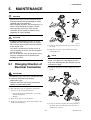
5.1
5.2
Changing Direction of Electrical Connection ................................................ 5-1
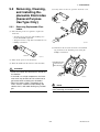
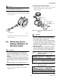
Removing, Cleaning, and Installing Replaceable Electrodes
(General-Purpose Use Type Only) ................................................................. 5-2
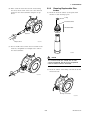
5.2.1 Removing Replaceable Electrodes .......................................................... 5-2
5.2.2 Cleaning Replaceable Electrodes ............................................................ 5-3
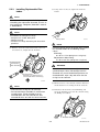
5.2.3 Installing Replaceable Electrodes ............................................................ 5-4
5.3 Removing and Installing Adapters for Sanitary Types .................................. 5-5
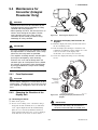
5.4 Maintenance for Converter (Integral Flowmeter Only) ................................. 5-7
5.4.1 Fuse Replacement .................................................................................... 5-7
5.4.2 Changing the Direction of the Display Unit ............................................ 5-7
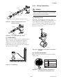
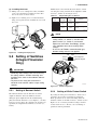
5.5 Setting of Switches (Integral Flowmeter Only) ............................................. 5-8
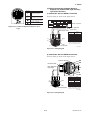
5.5.1 Setting of Burnout Switch ....................................................................... 5-8
5.5.2 Setting of Write Protect Switch ............................................................... 5-8
5.6 Regular Inspection Items ................................................................................ 5-9
5.7 Excitation Coil and Insulation Resistance Check
(Remote Flowtube Only) ................................................................................ 5-9
5.8 Maintenance of the LCD Display ................................................................... 5-9
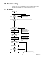
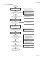
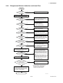
5.9 Troubleshooting ............................................................................................. 5-10
5.9.1 No Indication ......................................................................................... 5-10
5.9.2 Unstable Zero ......................................................................................... 5-11
5.9.3 Disagreement Between Indication and Actual Flow .............................. 5-12
6.
OUTLINE................................................................................................................. 6-1
7.
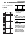
PED (PRESSURE EQUIPMENT DIRECTIVE) ................................................ 7-1
8.
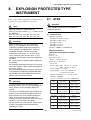
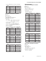
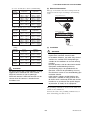
EXPLOSION PROTECTED TYPE INSTRUMENT ......................................... 8-1
8.1
8.2
8.3
8.4
8.5
ATEX .............................................................................................................. 8-1
FM ................................................................................................................... 8-5
CSA ................................................................................................................. 8-6
IECEx .............................................................................................................. 8-8
TIIS ................................................................................................................ 8-12
INSTALLATION AND OPERATING PRECAUTIONS
FOR TIIS FLAMEPROOF EQUIPMENT ......................................................... EX-B03E
REVISION RECORD
ii
IM 01E20D01-01E
1. INTRODUCTION
1.
INTRODUCTION
This instrument has been adjusted at the factory before
shipment.
• All rights are reserved. No part of this manual may
be reproduced in any form without Yokogawa's
written permission.
• Yokogawa makes no warranty of any kind with
regard to this material, including, but not limited to,
implied warranties of merchantability and suitability
for a particular purpose.
• All reasonable effort has been made to ensure the
accuracy of the contents of this manual. However,
if any errors or omissions are found, please inform
Yokogawa.
• Yokogawa assumes no responsibilities for this
product except as stated in the warranty.
• Please note that this user's manual may not be
revised for any specification changes, construction
changes or operating part changes that are not
considered to affect function or performance.
• If the customer or any third party is harmed by the
use of this product, Yokogawa assumes no responsibility for any such harm owing to any defects in the
product which were not predictable, or for any
indirect damages.
To ensure correct use of the instrument, please read
this manual thoroughly and fully understand how to
operate the instrument before operating it.
NOTE
This manual describes the hardware configuration of integral flowmeter and remote flowtube of
the AXF magnetic flowmeters.
For details of the “basic operating procedures”,
“parameter description”, “operation via BRAIN
terminal (BT200)”, “operation via HART communicator”, and “actual operation” for the AXF
integral flowmeter, see the user’s manual of the
AXF Integral Flowmeter [Software Edition] (IM
01E20C02-01E).
For FOUNDATION Fieldbus protocol (Converter
Output Signal and Communication suffix code; F), please refer to IM 01E20F02-01E.
For PROFIBUS PA protocol (Converter Output
Signal and Communication suffix code; -G),
please refer to IM 01E20F12-01E.
Safety and Modification Precautions
• The following general safety precautions must be
observed during all phases of operation, service, and
repair of this instrument. Failure to comply with
these precautions or with specific WARNINGS
given elsewhere in this manual violates safety
standards of design, manufacture, and intended use
of the instrument. Yokogawa assumes no liability for
the customer's failure to comply with these requirements. If this instrument is used in a manner not
specified in this manual, the protection provided by
this instrument may be impaired.
• Yokogawa will not be liable for malfunctions or
damage resulting from any modification made to this
instrument by the customer.
• The following safety symbol marks are used in this
user's manual and instrument.
NOTE
For details of the AXFA11G magnetic flowmeter
converter, see the IM 01E20C01-01E instruction
manual. For details of the AXFA14G and
AXFA14C magnetic flowmeter converter, see the
IM 01E20C02-01E instruction manual.
NOTE
When describing the model name like
AXFC in this manual, "" means any of
the following.
002, 005, 010, 015, 025, 032, 040, 050, 065,
080, 100, 125, 150, 200, 250, 300, 350, 400
WARNING
Regarding This User’s Manual
• This manual should be provided to the end user.
• Before use, read this manual thoroughly to comprehend its contents.
• The contents of this manual may be changed
without prior notice.
A WARNING sign denotes a hazard. It calls
attention to procedure, practice, condition or the
like, which, if not correctly performed or adhered
to, could result in injury or death of personnel.
1-1
IM 01E20D01-01E
1. INTRODUCTION
1.1 Using the Magnetic
Flowmeter Safely
CAUTION
A CAUTION sign denotes a hazard. It calls
attention to procedure, practice, condition or the
like, which, if not correctly performed or adhered
to, could result in damage to or destruction of
part or all of the product.
(1) Installation
WARNING
• Installation of the magnetic flowmeter must be
performed by expert engineer or skilled personnel. No operator shall be permitted to perform
procedures relating to installation.
• The magnetic flowmeter must be installed
within the specification conditions.
• The magnetic flowmeter is a heavy instrument.
Be careful that no damage is caused to personnel through accidentally dropping it, or by
exerting excessive force on the magnetic
flowmeter. When moving the magnetic flowmeter, always use a trolley and have at least two
people carry it.
• When the magnetic flowmeter is processing hot
fluids, the instrument itself may become extremely hot. Take sufficient care not to get
burnt.
• Where the fluid being processed is a toxic
substance, avoid contact with the fluid and
avoid inhaling any residual gas, even after the
instrument has been taken off the piping line for
maintenance and so forth.
• Do not apply excessive weight, for example, a
person stepping on the magnetic flowmeter.
• All procedures relating to installation must
comply with the electrical code of the country
where it is used.
IMPORTANT
An IMPORTANT sign denotes that attention is
required to avoid damage to the instrument or
system failure.
NOTE
A NOTE sign denotes information necessary for
essential understanding of operation and features.
Protective grounding terminal
Functional grounding terminal
(This terminal should not be used as a protective
grounding terminal.)
Alternating current
Direct current
(2) Wiring
WARNING
• The wiring of the magnetic flowmeter must be
performed by expert engineer or skilled personnel. No operator shall be permitted to perform
procedures relating to wiring.
• When connecting the wiring, check that the
supply voltage is within the range of the voltage
specified for this instrument before connecting
the power cable. In addition, check that no
voltage is applied to the power cable before
connecting the wiring.
• The protective grounding must be connected
securely at the terminal with the
mark to
avoid danger to personnel.
1-2
IM 01E20D01-01E
1. INTRODUCTION
(3) Operation
(5) Explosion Protected Type Instrument
WARNING
WARNING
• When opening the cover, wait for more than 10
minutes after turning off the power. Only
expert engineer or skilled personnel are permitted to open the cover.
• Do not open the cover in wet weather or humid
environment. When the cover is open, stated
enclosure protection is not applicable.
• Be sure to set parameters as “Protect” on the
write protect function after finish of parameter
setting work.
Under extremely rare case, the infra-red
switches may respond unexpectedly in such
conditions as sticking ball of water or extraneous substances on the surface of display panel
glass according to the principle of infra-red
switch operation.
Its probability rises in such cases as sticking
rain water by storm or other similar situation
and washing up work near flowmeter installation place.
Either to illuminate or stop illuminating the infrared switches by the flashlight may cause the
malfunction.
Refer to “Parameter Description” in the manual
IM 01E20C02-01E and Subsection 5.5.2
reading the write protect function in detail.
• Magnetic flowmeters with the model name
AXFC are products which have been
certified as explosion proof type instruments.
Strict limitations are applied to the structures,
installation locations, external wiring work,
maintenance and repairs, etc. of these instruments. Sufficient care must be taken, as any
violation of the limitations may cause dangerous situations.
Be sure to read Chapter 8 before handling the
instruments. The description in Chapter 8 is
prior to the other description in this user’s
manual.
For TIIS flameproof type instruments, be sure
to read “INSTALLATION AND OPERATING
PRECAUTIONS FOR TIIS FLAMEPROOF
EQUIPMENT” at the end of this manual.
• Only trained persons use this instrument in the
industrial location.
• The protective grounding
must be connected
to a suitable IS grounding system.
• Take care not to generate mechanical spark
when access to the instrument and peripheral
devices in hazardous locations.
(6) European Pressure Equipment Directive
(PED)
(4) Maintenance
WARNING
WARNING
• When using the instrument in compliance with
PED, be sure to read Chapter 7 before use.
• Maintenance of the magnetic flowmeter should
be performed by the trained personnel having
knowledge of safety standard. No operator
shall be permitted to perform any operations
relating to maintenance.
• When opening the cover, wait for more than 10
minutes after turning off the power.
• Do not open the cover in wet weather or humid
environment. When the cover is open, stated
enclosure protection is not applicable.
• Always conform to maintenance procedures
outlined in this manual. If necessary, contact
Yokogawa.
• Care should be taken to prevent the buildup of
dirt, dust or other substances on the display
panel glass or name plate. If these surfaces do
get dirty, wipe them clean with a soft dry cloth.
(7) Modification
WARNING
• Yokogawa will not be liable for malfunctions or
damage resulting from any modification made
to this instrument by the customer.
(8) Product Disposal
The instrument should be disposed of in accordance
with local and national legislation/regulations.
(9) Authorized Representative in EEA
In relation to the CE Marking, The authorized
representative for this product in the EEA (European
Economic Area) is:
Yokogawa Europe B.V.
Euroweg 2, 3825 HD Amersfoort, The Netherlands
1-3
IM 01E20D01-01E
1. INTRODUCTION
1.2 Warranty
1.3 Combination Remote
Converters
• The terms of this instrument that are guaranteed are
described in the quotation. We will make any repairs
that may become necessary during the guaranteed
term free of charge.
• Please contact our sales office if this instrument
requires repair.
• If the instrument is faulty, contact us with concrete
details about the problem and the length of time it
has been faulty, and state the model and serial
number. We would appreciate the inclusion of
drawings or additional information.
• The results of our examination will determine
whether the meter will be repaired free of charge or
on an at-cost basis.
IMPORTANT
• According to suffix codes, AXF remote flowtube
should be combined with one of the following
remote converters.
AXFA11G remote converter
AXFA14G remote converter
AXFA14C remote converter
Contact Yokogawa before using it in combination with flowtubes other than those listed
above.
• For ATEX, IECEx or TIIS certified AXF remote
flowtube, it is only approved to be combined
with AXFA14 converter.
• If the converter combined with AXF magnetic
flowmeter's remote flowtube is changed from
AXFA11 to AXFA14 or vice versa, the meter
factor of the remote flowtube must be readjusted according to its flow calibration.
The guarantee will not apply in the following
cases:
• Damage due to negligence or insufficient maintenance on the part of the customer.
• Problems or damage resulting from handling,
operation or storage that violates the intended use
and specifications.
• Problems that result from using or performing
maintenance on the instrument in a location that
does not comply with the installation location
specified by Yokogawa.
• Problems or damage resulting from repairs or
modifications not performed by Yokogawa or
someone authorized by Yokogawa.
• Problems or damage resulting from inappropriate
reinstallation after delivery.
• Problems or damage resulting from disasters such as
fires, earthquakes, storms, floods, or lightning strikes
and external causes.
Trademarks:
• All the brands or names of Yokogawa Electric’s
products used in this manual are either trademarks or
registered trademarks of Yokogawa Electric Corporation.
• All other company and product names mentioned in
this manual are trade names, trademarks or registered trademarks of their respective companies.
• In this manual, trademarks or registered trademarks
are not marked with ™ or ®.
1-4
IM 01E20D01-01E
1. INTRODUCTION
1.4 ATEX Documentation
This is only applicable to the countries in European Union.
1-5
IM 01E20D01-01E
2. HANDLING PRECAUTIONS
2.
HANDLING PRECAUTIONS
This instrument has been inspected carefully at the
factory before shipment. When the instrument is
delivered, visually check that no damage has occurred
during transportation and check that mounting parts are
attached.
Read this section carefully as it contains important
information on handling this instrument. Refer to the
relevant sections for information not contained in this
section. If you have any problems or questions, please
contact Yokogawa sales office.
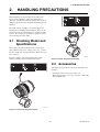
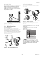
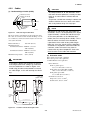
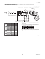
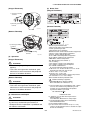
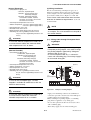
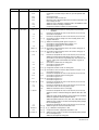
2.1 Checking Model and
Specifications
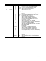
The model code and specifications are found on the
name plate located on the outside of the case. Check
that the model code and specifications match what you
have ordered.
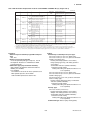
F0202.EPS
Be sure you have your model number and serial
number available when contacting Yokogawa.
Figure 2.1.2 Name Plate (Remote Flowtube)
2.2 Accessories
Check that the parts shown below are included in the
package:
• Centering device (wafer type only): 1 pc.
• Hexagonal wrench: 2 pcs. (one each of 1.5 mm and 3
mm nominal sizes)
F0201.EPS
Figure 2.1.1 Name Plate (Integral Flowmeter)
2-1
IM 01E20D01-01E
2. HANDLING PRECAUTIONS
Explosion protected type:
Explosion protect types can be installed in hazardous areas according to the types of gases for which
they are certified. See the description in Chapter 8
and “INSTALLATION AND OPERATING PRECAUTIONS FOR TIIS FLAMEPROOF EQUIPMENT” in this user's manual.
2.3 Storage Precautions
If the instrument is to be stored for a long period of
time after delivery, observe the following points.
The instrument should be stored in its original
packing condition in the storage location.
Select a storage location that fulfils the following
conditions:
• A place where it will not be exposed to rain or
water
• A place subject to minimal vibrations or shocks
• Temperature and humidity levels should be as
follows:
Temperature: -30 to 70°C
Humidity: 5 to 80% RH (no condensation)
The preferred ambient temperature and
humidity levels are 25°C and approximately
65% RH.
If the AXF magnetic flowmeter is transferred to the
installation site and stored without being installed,
its performance may be impaired due to the infiltration of rainwater and so forth. Be sure to install and
wire the AXF magnetic flowmeter as soon as
possible after transferring it to the installation
location.
2.4 Installation Location
Precautions
Select the installation location with consideration to the
following items to ensure long-term stable operation of
the instrument.
Ambient Temperature:
Avoid installing the instrument in locations with
constantly fluctuating temperatures. If the location is
subject to radiant heat from the plant, provide heat
insulation or improve ventilation.
Atmospheric Condition:
Avoid installing the instrument in a corrosive
atmosphere. In situations where this is unavoidable,
consider ways to improve ventilation and to prevent
rainwater from entering and being retained in the
conduit pipes.
Vibrations or Shocks:
Avoid installing the instrument in a place subject to
shocks or vibrations.
2-2
IM 01E20D01-01E
3. INSTALLATION
3.
INSTALLATION
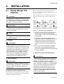
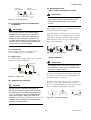
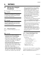
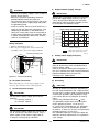
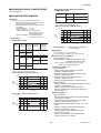
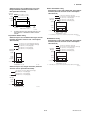
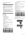
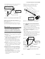
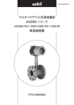
3.1 Piping Design Precautions
Based on JIS B 7554 and our piping condition test
data, we recommend the piping conditions as shown in
the following figures.
When installing two or more magnetic flowmeters on a
single pipe, provide a run of at least 10D between
them.
WARNING
Installation of the magnetic flowmeter must be
performed by expert engineer or skilled personnel. No operator shall be permitted to perform
procedures relating to installation.
Gate valve
fully open
5D or more
Tee
IMPORTANT
Reducer
pipe
D: Flowtube Size
Expander
pipe
2D
or more 0 is allowable. 0 is allowable. 10D or more 2D or more
90-degree bent
Various valves
2D
5D or more 0 is allowable. 5D or more 0 is allowable.10D or more or more
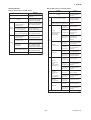
Design piping correctly, referring to the following
to prevent damage to flowtube and to assure
accurate measuring.
F08.EPS
Figure 3.1.1
Required Lengths of Straight Runs
*1: Do not install anything in the vicinity that may
interfere with the magnetic field, induced
signal voltages, or flow velocity distributions of
the flowmeter.
NOTE
This chapter describes the remote flowtube as
an example. The same attention must be paid to
the integral flowmeter.
*2: A straight run may not be required on the
downstream side of the flowmeter. However, if
a downstream valve or other fitting causes
irregularity or deviation in flows, provide a
straight run of 2D to 3D on the downstream
side.
(1) Location
IMPORTANT
Install the flowmeter in a location where it is not
exposed to direct sunlight. The minimum ambient temperature is limited by the minimum fluid
temperature of the flowtube (the lining). For
more information, refer to Chapter 6. The flowmeter may be used in an ambient humidity
where the relative humidity ranges from 0 to
100%. However, avoid long-term continuous
operation at relative humidity above 95%.
*3: The valves shall be mounted on the downstream side so that deviated flows do not
occur in the flowtube and to avoid startup from
an empty condition.
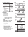
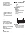
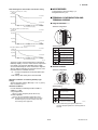
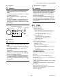
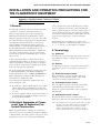
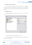
(4) Maintaining Stable Fluid Conductivity
IMPORTANT
Do not install the flowmeter where fluid conductivity tends to become uneven. If chemicals are
fed near the upstream side of a magnetic
flowmeter, they may affect the flow rate’s indications. To avoid this situation, it is recommended
that the chemical feed ports be located on the
downstream side of the flowmeter. If it is unavoidable that chemicals must be fed on the
upstream side, provide a sufficient length of
straight run (approximately 50D) to ensure the
proper mixture of fluids.
(2) Noise Avoidance
IMPORTANT
The flowmeter should be installed away from
electrical motors, transformers, and other power
sources in order to avoid interference with
measurement.
(3) Required Lengths of Straight Runs
To maintain accurate measurement, see JIS B 7554
which explains the requirements for upstream piping
conditions of magnetic flowmeters.
3-1
IM 01E20D01-01E
3. INSTALLATION
(Incorrect)
Upstream side
(9) Mounting Positions
• Pipes must be fully filled with liquids.
(Correct)
Downstream side
IMPORTANT
It is essential that pipes remain fully filled at all
times, otherwise flow rate indications may be
affected and measurement errors may be
caused.
F0302.EPS
Figure 3.1.2
Chemical Injection
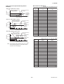
(5) Precautions for Use of Liquid Sealing
Compounds
Piping shall be designed so as to maintain the interior
of the flowtube filled with fluids.
IMPORTANT
Care must be taken in using liquid sealing
compounds on the piping, as it may have a
negative influence on the flow indications by
flowing out and covering the surfaces of an
electrode or grounding ring. In particular, care
must be taken if a liquid sealing compound is
used in the case of vertical piping.
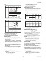
Vertical mounting is effective in such cases as when
fluids tend to separate or solid matter may be precipitated. When employing vertical mounting, direct the
fluids from the bottom to the top to ensure that the
pipes remain fully filled.
(Correct)
(Incorrect)
(Correct)
h
h>0
(Incorrect)
h
(6) Service Area
Select locations where there is adequate space to
service installing, wiring, overhauling, etc.
h>0
F0304.EPS
Figure 3.1.4
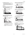
(7) Bypass Line
It is recommended to install a bypass line to facilitate
maintenance and zero adjustment.
Mounting Positions
• Avoid air bubbles.
IMPORTANT
Bypass valve
If air bubbles enter a measurement pipe, flow
rate indications may be affected and measurement errors may be caused.
Block valve
Block valve
Figure 3.1.3
In cases where fluids contain air bubbles, piping must
be designed to prevent them from accumulating in the
measurement pipe of a flowtube.
F0303.EPS
Bypass Line
(8) Supporting the Flowmeter
If a valve exists near the flowmeter, try to mount the
flowmeter on the valve’s upstream side in order to
prevent a possible reduction of pressure inside the pipe,
thereby avoiding the possibility of air bubbles.
CAUTION
Do not secure the flowmeter separately to
prevent the vibrations, shocks, and expansion
and contraction forces of the piping from affecting it. Fix the pipes first, then support the flowmeter with the pipes. With extra small-sized
flowmeters (size 2.5 to 10 mm (0.1 to 1.0 in.)), in
particular, fix the flowmeter in parallel with the
piping on a mounting base.
(Incorrect)
(Correct)
(Correct)
(Incorrect)
Valve
F10.EPS
Figure 3.1.5
3-2
Avoiding Air Bubbles
IM 01E20D01-01E
3. INSTALLATION
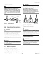
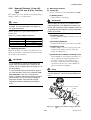
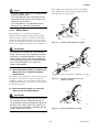
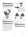
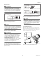
• Mounting orientation
CAUTION
In order to lift a magnetic flowmeter that is fitted
with eyebolts, proceed as in Figure 3.2.1. Never
lift it using a bar passed through the flowtube as
this damages the liner severely.
When lifting the magnetic flowmeter in vertical
position, eyebolts (or eyenuts and bolts) are
necessary. Attach them to the flange bolt holes,
and then lift the magnetic flowmeter.
IMPORTANT
If electrodes are perpendicular to the ground, air
bubbles near the top or precipitates at the
bottom may cause measurement errors. Ensure
that the terminal box of a remote flowtube and
converter of an integral flowmeter are mounted
above the piping to prevent water from entering
them.
Correct
Incorrect
Incorrect
Air bubble
Electrode
Electrode
Precipitate
Water can
seep into
the terminal
box.
F0306.EPS
Figure 3.1.6
Horizontal position
Mounting Orientation
Vertical position
F0307.EPS
Figure 3.2.1
3.2 Handling Precautions
Lifting Flowmeter
(2) Avoid Shocks from Impact
CAUTION
WARNING
Care should be taken not to drop the flowmeter
or expose it to excessive shock. In particular, be
careful not to subject the flange surface to
shock. This may lead to liner damage which will
result in inaccurate readings.
The magnetic flowmeter is a heavy instrument.
Be careful that no damage is caused to personnel through accidentally dropping it, or by
exerting excessive force on the magnetic flowmeter. When moving the magnetic flowmeter,
always use a trolley and have at least two
people carry it.
(3) Flange Protection Covers
IMPORTANT
NOTE
Keep the protective covering (i.e. the corrugated
cardboard or other cushioning material) in place
over the flange except when mounting the
flowmeter to the pipe.
This chapter describes the remote flowtube as
an example. The same attention must be paid to
the integral flowmeter.
3.2.1
General Precautions
(1) Precaution during Transportation
The magnetic flowmeter is packed tightly. When it is
unpacked, pay attention to prevent damaging the
flowmeter. To prevent accidents while it is being
transported to the installing location, transport it to the
site in its original packing.
3-3
IM 01E20D01-01E
3. INSTALLATION
(4) Terminal Box Cover
(2) Inside a newly installed pipeline, there may be
some foreign substances such as residue from
welding or wood chips. Remove them by flushing
the piping before mounting the flowmeter. This
prevents the lining from being damaged, as well as
the occurrence of erroneous measured signals
resulting from foreign substances passing through
the flowtube during measurement.
IMPORTANT
As it is possible that the insulation will deteriorate, do not open the terminal box cover until it
is time to wire it.
(5) Long-term Non-use
3.3 Mounting Procedures
IMPORTANT
It is not desirable to leave the flowmeter unused
for a long term after installation. If this situation
is unavoidable, take care of the flowmeter by
observing the following.
IMPORTANT
Do not forget to insert gaskets from Yokogawa
between pipes and flowmeter, which shall be
supplied when the flowmeter has ceramics lining
with no grounding rings.
In case of grounding rings to be supplied and
attached later, these gaskets shall be inserted
between grounding rings and flowmeter.
• Confirmation of sealing conditions for the
flowmeter
Confirm that the terminal box screw and wiring ports
are well sealed. Equip the conduit piping with drain
plugs or waterproof glands to prevent moisture or
water from penetrating into the flowmeter through the
conduit.
NOTE
• The tightening torque value to which gaskets
must be tightened varies depending on the
type and external dimensions of the lining and
the gasket. In this section, the tables indicating
tightening torque values include the corresponding gasket types. The internal diameters
of the gaskets are close to those of the grounding rings.
• For fluids capable of potentially permeating
PFA linings (such as nitric acid, hydrofluoric
acid, or sodium hydrate at high temperatures),
different tightening torque values must be
applied. The tables of these torque values is
indicated in this section.
• For replacement models for the earlier ADMAG
or ADMAG AE, the tightening torque values in
the tables can be applied if their process
connections, the lining types, and the nominal
sizes are the same.
• Regular inspections
Inspect the sealing conditions as mentioned above, and
the inside of the terminal box at least once a year.
Also, due to rain, etc. when it is suspected that water
may have penetrated into the inside flowmeter perform
supplementary inspections.
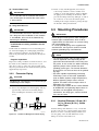
3.2.2
Flowmeter Piping
CAUTION
Misaligned or slanted piping can lead to leakage
and damage to the flanges.
(1) Correct any misaligned or slanted piping, and any
gaps that may exist between mounting flanges
before installing the flowmeter (refer to Figure
3.2.2).
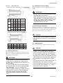
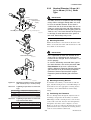
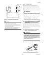
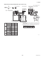
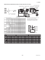
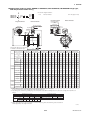
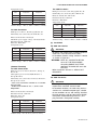
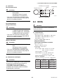
3.3.1
Slanted
Ceramics linings with diameters of 2.5, 5 or 10 mm
(0.1, 0.2 or 0.4 in.) are connected using union joints.
Weld or screw the connecting fittings in Table 3.3.1
onto the piping. The external dimensions of the
fittings are shown in the Table 3.3.1.
Misaligned
F0308.EPS
Figure 3.2.2
Nominal Diameter 2.5 mm (0.1
in.) to 10 mm (0.4 in.), Union
Joint Type
Slanted and Misaligned Flowmeter Piping
3-4
IM 01E20D01-01E
3. INSTALLATION
Table 3.3.1
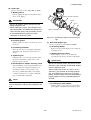
(2) Connecting Process Piping
Weld or screw the connection fittings to the process
piping.
Fitting Dimensions
Screw joint (process connection codes: GUR and GUN)
Unit: mm (inch)
D
0
A
B C -0.1
4
(0.16)
Size
IMPORTANT
• Be sure to pass the connection fittings through
the union joint nuts in advance.
• When welding the fittings, pay attention to the
edge preparation, level differences between the
fittings and the piping, and the welding current
to avoid deforming the piping or causing
stagnation portion of the fluid.
11.5(0.45)
30(1.18)
Code
2.5
(0.1)
GUR
5
(0.2)
GUR
10
(0.4)
GUR
GUN
GUN
GUN
A
B
C
22
(0.87)
22
(0.87)
22
(0.87)
22
(0.87)
25
(0.98)
25
(0.98)
8
(0.31)
8
(0.31)
8
(0.31)
8
(0.31)
10
(0.39)
10
(0.39)
18.5
(0.73)
18.5
(0.73)
18.5
(0.73)
18.5
(0.73)
22.5
(0.89)
22.5
(0.89)
D
R1/4
NPT1/4
R1/4
(3) Positioning the Flowmeter
Install the flowmeter on a mounting base and position
it so that the center axis of the flowtube is aligned with
that of the process piping. Then screw the union joint
nuts to the connecting ports of the flowmeter.
NPT1/4
R3/8
NPT3/8
T0301.EPS
Weld joint (process connection code: GUW)
Unit: mm (inch)
CAUTION
+0.3
0
A B
C
Ceramics pipes may be damaged if the nuts are
tightened when the center axes are not properly
aligned.
D
10(0.39)
4
(0.16)
Size
0
-0.1
35(1.38)
Code
A
B
C
(4) Tightening Nuts
Use a torque wrench to tighten the union joint nuts.
D
2.5 (0.1) GUW 22(0.87) 8(0.31) 14.3(0.56) 18.5(0.73)
5 (0.2)
GUW 22(0.87) 8(0.31) 14.3(0.56) 18.5(0.73)
10 (0.4) GUW 25(0.98) 10(0.39) 17.8(0.70) 22.5(0.89)
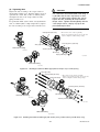
CAUTION
T0302.EPS
Tighten the nuts according to the torque values
in Table 3.3.2 when the gaskets are Valqua
#7020 (standard) or alkali-resistant gaskets for
the metal piping (optional code GF). For permeable fluid (such as nitric acid, hydrofluoric acid or
sodium hydrate at high temperature), tighten the
nuts according to the torque values in Table
3.3.3.
As the gasket material is fluorocarbon PTFE, it is
possible that the nuts may loosen as time
passes. Retighten the nuts if this is the case. Be
sure to use the gasket (thickness is 1.5 mm)
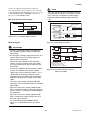
which comes with the flowmeter.
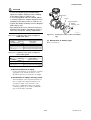
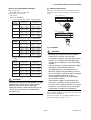
(1) Mounting Direction
Mount the flowmeter so that the flow direction of the
fluid to be measured is in line with the direction of the
arrow mark on the flowmeter.
IMPORTANT
If it is impossible to match the direction of the
arrow mark, the direction of the electrical connection can be changed. Refer to Section 5.1 to
do this properly.
In case the fluid being measured flows against
the arrow direction, refer to the parameter J20:
Flow Direction in the user’s manual of the
AXFA11 Magnetic Flowmeter Remote Converter
(IM 01E20C01-01E) or the AXFA14 Magnetic
Flowmeter Remote Converter/AXF Integral
Flowmeter [Software Edition] (IM 01E20C0201E).
3-5
IM 01E20D01-01E
3. INSTALLATION
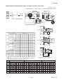
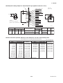
3.3.2
IMPORTANT
Gasket
Connecting fitting
Union joint nut
Use bolts and nuts in compliance with the flange
ratings. When stud-type through-bolts are used,
be sure the outside diameter of the shank is
smaller than that of the thread ridge. Be sure to
choose a gasket with inner and outer diameters
that does not protrude inside the piping (refer to
Table 3.3.16). If the inner diameter of the gasket
is too large, or outer diameter of the gasket is
too small, fluid leakage may result.
*Piping
*Mounting base
Nominal Diameter 2.5 mm (0.1
in.) to 40 mm (1.5 in.), Wafer
Type
*: To be provided by user
F0309a.EPS
(1) Mounting Direction
Mount the flowmeter so that the flow direction of the
fluid to be measured is in line with the direction of the
arrow mark on the flowmeter.
IMPORTANT
If it is impossible to match the direction of the
arrow mark, the direction of the electrical connection can be changed. Refer to Section 5.1 to
do this properly.
In case the fluid being measured flows against
the arrow direction, refer to the parameter J20:
Flow Direction in the user’s manual of the
AXFA11 Magnetic Flowmeter Remote Converter
(IM 01E20C01-01E) or the AXFA14 Magnetic
Flowmeter Remote Converter/AXF Integral
Flowmeter [Software Edition] (IM 01E20C0201E).
Horizontal mounting
F0309b.EPS
Vertical mounting
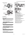
(2) Mounting Centering Devices
To maintain concentricity of the flowmeter with the
pipes, install centering devices on the Mini-flanges of
the flowmeter. Use the appropriate centering devices
according to the nominal diameter and the flange
ratings.
F0309c.EPS
Figure 3.3.1
Mounting Procedure for Union Joint Type
(size: 2.5 mm (0.1 in.) to 10 mm (0.4 in.))
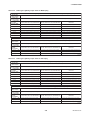
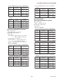
Table 3.3.2
Tightening torque values for Union Joint
Type
Torque (N-m / {kgf-cm} / [in-lbf])
Size mm (inch)
2.5 (0.1)
9 to 12 / {91.77 to 122.4} / [79.66 to 106.2]
5 (0.2)
9 to 12 / {91.77 to 122.4} / [79.66 to 106.2]
10 (0.4)
14 to 18 / {142.8 to 183.5} / [123.9 to 159.3]
(3) Positioning the Flowmeter
Pass two through-bolts through the adjacent holes of
both flanges and position the flowmeter so that the
Mini-flanges and the centering devices come in close
contact with each other. Pass the other through-bolts
through the other holes (refer to Figure 3.3.2 and
Figure 3.3.3). In case stud-type through-bolts are used,
position them in such a way that the centering devices
come in contact with the bolt threads.
T0303.EPS
Table 3.3.3
Tightening torque values for Union Joint
Type and Permeable Fluids
Torque (N-m / {kgf-cm} / [in-lbf])
Size mm (inch)
2.5 (0.1)
11 to 15 / {112.2 to 153} / [97.36 to 132.8]
5 (0.2)
11 to 15 / {112.2 to 153} / [97.36 to 132.8]
10 (0.4)
17 to 23 / {173.4 to 234.5} / [150.5 to 203.6]
T0304.EPS
3-6
IM 01E20D01-01E
3. INSTALLATION
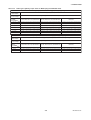
(4) Tightening Nuts
Tighten the nuts according to the torque values for
metal piping in Table 3.3.4. For PVC piping, select an
optional code of GA, GC, or GD, use rubber gaskets
and tighten the nuts to the torque values for PVC
piping in Table 3.3.5.
For permeable fluids (such as nitric acid, hydrofluoric
acid, or sodium hydrate at high temperatures), tighten
the nuts according to the torque values in Table 3.3.6.
CAUTION
For a flowmeter with fluorocarbon PFA lining, it
is possible that the nuts may loosen as time
passes, so tighten them regularly. Be sure to
tighten the nuts according to the prescribed
torque values. Tighten them diagonally with the
same torque values, step by step up to the
prescribed torque value.
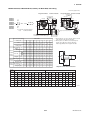
*Through-bolt (four units)
*: These items can be ordered optionally.
If they are provided by the user, choose nuts and
bolts in compliance with the flange ratings.
Centering device (two units)
*Nut (eight units)
Horizontal mounting
*Gasket (two units)
F0310b.EPS
Mini-flange
Piping-side flange
F0310a.EPS
Vertical mounting
F0310c.EPS
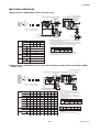
Figure 3.3.2
Mounting Procedure for Wafer Type (size: 2.5 mm (0.1 in.) to 15 mm (0.5 in.))
*Nut (eight units)
*Through-bolt (four units)
Piping-side flange
*: These items can be ordered optionally.
If they are provided by the user, choose nuts and
bolts in compliance with the flange ratings.
Centering device (two units)
Mini-flange
Horizontal mounting
F0311b.EPS
*Gasket (two units)
F0311a.EPS
Vertical mounting
F0311c.EPS
Figure 3.3.3
Mounting Procedure for Wafer Type (size: 25 mm (1.0 in.), 32 mm (1.25 in.), and 40 mm (1.5 in.))
3-7
IM 01E20D01-01E
3. INSTALLATION
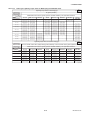
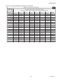
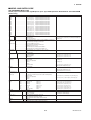
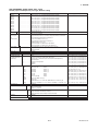
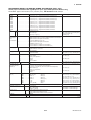
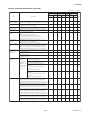
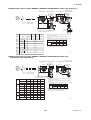
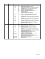
Table 3.3.4
Wafer Type Tightening Torque Values for Metal Piping
Tightening torque values for PFA/Polyurethane Rubber lining type (N-m / {kgf-cm} / [in-lbf])
Gasket types
within flowtube
No gasket (standard)
Gasket types
for user’s flange
Non-asbestos fiber gasket, PTFE-sheathed non-asbestos gasket (optional codes BCF and BSF), or the equivalent in hardness
Flange ratings
Size
JIS 10K, ANSI Class 150, and DIN PN10
mm (inch)
JIS 20K, ANSI Class 300, and DIN PN16
DIN PN40
2.5 (0.1)
7.2 to 8.4 / {73.42 to 85.66} / [63.72 to 74.35]
7.3 to 8.4 / {74.44 to 85.66} / [64.61 to 74.35]
7.6 to 8.4 / {77.5 to 85.66} / [67.26 to 74.35]
5 (0.2)
7.2 to 8.4 / {73.42 to 85.66} / [63.72 to 74.35]
7.3 to 8.4 / {74.44 to 85.66} / [64.61 to 74.35]
7.6 to 8.4 / {77.5 to 85.66} / [67.26 to 74.35]
10 (0.4)
7.2 to 8.4 / {73.42 to 85.66} / [63.72 to 74.35]
7.3 to 8.4 / {74.44 to 85.66} / [64.61 to 74.35]
7.6 to 8.4 / {77.5 to 85.66} / [67.26 to 74.35]
15 (0.5)
7.2 to 8.4 / {73.42 to 85.66} / [63.72 to 74.35]
7.3 to 8.4 / {74.44 to 85.66} / [64.61 to 74.35]
7.6 to 8.4 / {77.5 to 85.66} / [67.26 to 74.35]
25 (1.0)
23.5 to 27.3 / {239.6 to 278.4} / [208 to 241.6]
32 (1.25)
26.2 to 30.5 / {267.2 to 311} / [231.9 to 269.9]
23.7 to 27.3 / {241.7 to 278.4} / [209.8 to 241.6] 22.3 to 27.3 / {227.4 to 278.4} / [197.4 to 241.6]
26.6 to 30.5 / {271.2 to 311} / [235.4 to 269.9]
28.0 to 30.5 / {285.5 to 311} / [247.8 to 269.9]
36.2 to 42.4 / {369.1 to 432.4} / [320.4 to 375.3] 36.9 to 42.4 / {376.3 to 432.4} / [326.6 to 375.3] 39.1 to 42.4 / {398.7 to 432.4} / [346.1 to 375.3]
40 (1.5)
Tightening torque values for Ceramics lining type (N-m / {kgf-cm} / [in-lbf])
Gasket types
within flowtube
Fluororesin with ceramic fillers (Valqua #7020) (standard) gasket, or fluororesin with carbon gasket (optional code GF)
Gasket types
Non-asbestos gasket, PTFE-sheathed non-asbestos gasket (optional codes BCF and BSF), or the equivalent in hardness
for user’s flange
Flange ratings
Size
JIS 10K, ANSI Class 150, and DIN PN10 JIS 20K, ANSI Class 300, and DIN PN16
DIN PN40
mm (inch)
15 (0.5)
6.8 to 11.0 / {69.3 to 112.2} / [60.2 to 97.4]
6.8 to 11.0 / {69.3 to 112.2} / [60.2 to 97.4]
6.6 to 11.0 / {67.3 to 112.2} / [58.4 to 97.4]
25 (1.0)
18.9 to 24.5 / {192.7 to 249.8} / [167.3 to 216.8] 19.1 to 24.5 / {194.8 to 249.8} / [169.0 to 216.8] 14.7 to 24.5 / {149.9 to 249.8} / [130.1 to 216.8]
40 (1.5)
34.5 to 45.7 / {351.8 to 466.0} / [305.4 to 404.5] 41.7 to 57.4 / {425.2 to 585.3} / [369.1 to 508.0] 34.5 to 57.4 / {351.8 to 585.3} / [305.4 to 508.0]
T0305.EPS
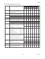
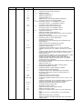
Table 3.3.5
Wafer Type Tightening Torque Values for PVC Piping
Tightening torque values for PFA lining type (N-m / {kgf-cm} / [in-lbf])
Gasket types
within flowtube
Fluororubber gasket (optional codes GA, GC, and GD)
Gasket types
for user’s flange
Fluororubber gasket, chloroprene rubber gasket (optional codes BSC and BCC), or the equivalent in hardness
Flange ratings
Size
JIS 10K, ANSI Class 150, and DIN PN10
mm (inch)
1.5 to 2.5 / {15.3 to 25.49} / [13.28 to 22.13]
2.5 (0.1)
JIS 20K, ANSI Class 300, and DIN PN16
DIN PN40
1.5 to 2.5 / {15.3 to 25.49} / [13.28 to 22.13]
1.5 to 2.4 / {15.3 to 24.47} / [13.28 to 21.24]
5 (0.2)
1.5 to 2.5 / {15.3 to 25.49} / [13.28 to 22.13]
1.5 to 2.5 / {15.3 to 25.49} / [13.28 to 22.13]
1.5 to 2.4 / {15.3 to 24.47} / [13.28 to 21.24]
10 (0.4)
1.5 to 2.5 / {15.3 to 25.49} / [13.28 to 22.13]
1.5 to 2.5 / {15.3 to 25.49} / [13.28 to 22.13]
1.5 to 2.4 / {15.3 to 24.47} / [13.28 to 21.24]
15 (0.5)
1.5 to 2.5 / {15.3 to 25.49} / [13.28 to 22.13]
1.5 to 2.5 / {15.3 to 25.49} / [13.28 to 22.13]
1.5 to 2.4 / {15.3 to 24.47} / [13.28 to 21.24]
25 (1.0)
4.9 to 8.1 / {49.97 to 82.6} / [43.37 to 71.69]
5.0 to 8.3 / {50.99 to84.64 } / [44.25 to 73.46]
4.3 to 7.2 / {43.85 to 73.42} / [38.06 to 63.72]
32 (1.25)
5.5 to 9.2 / {56.08 to 93.81} / [48.68 to 81.43] 5.7 to 9.5 / {58.12 to 96.87} / [50.45 to 84.08]
5.4 to 8.9 / {55.06 to 90.75} / [47.79 to 78.77]
40 (1.5)
7.7 to 12.9 / {78.52 to 131.5} / [68.15 to 114.2] 8.1 to 13.4 / {82.6 to 136.6} / [71.69 to 118.6] 7.5 to 12.5 / {76.48 to 127.5} / [66.38 to 110.6]
Tightening torque values for Ceramics lining type (N-m / {kgf-cm} / [in-lbf])
Gasket types
within flowtube
Fluororubber gasket (optional codes GA, GC, and GD)
Gasket types
Fluororubber gasket, chloroprene rubber gasket (optional codes BSC and BCC), or the equivalent in hardness
for user’s flange
Flange ratings
Size
JIS 10K, ANSI Class 150, and DIN PN10 JIS 20K, ANSI Class 300, and DIN PN16
DIN PN40
mm (inch)
15 (0.5)
0.8 to 1.4 / {8.2 to 14.3} / [7.1 to 12.4]
0.8 to 1.4 / {8.2 to 14.3} / [7.1 to 12.4]
0.8 to 1.4 / {8.2 to 14.3} / [7.1 to 12.4]
25 (1.0)
2.3 to 3.1 / {23.5 to 31.6} / [20.4 to 27.4]
2.4 to 3.1 / {24.5 to 31.6} / [21.2 to 27.4]
1.9 to 3.1 / {19.4 to 31.6} / [16.8 to 27.4]
40 (1.5)
4.4 to 6.0 / {44.9 to 61.2} / [38.9 to 53.1]
5.2 to 7.3 / {53.0 to 74.4} / [46.0 to 64.6]
4.4 to 7.3 / {44.9 to 74.4} / [38.9 to 64.6]
T0306.EPS
3-8
IM 01E20D01-01E
3. INSTALLATION
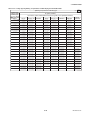
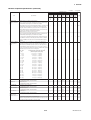
Table 3.3.6
Wafer Type Tightening Torque Values for Metal Piping and Permeable Fluids
Tightening torque values for PFA lining type (N-m / {kgf-cm} / [in-lbf])
Gasket types
within flowtube
No gasket (standard)
Gasket types
for user’s flange
PTFE-sheathed non-asbestos gasket (optional codes BCF and BSF), or the equivalent in hardness
Flange ratings
Size
JIS 10K, ANSI Class 150, and DIN PN10 JIS 20K, ANSI Class 300, and DIN PN16
DIN PN40
mm (inch)
10.8 to 12.4 / {110.1 to 126.4} / [95.59 to 109.7] 10.8 to 12.4 / {110.1 to 126.4} / [95.59 to 109.7] 11.1 to 12.4 / {113.2 to 126.4} / [98.24 to 109.7]
2.5 (0.1)
5 (0.2)
10.8 to 12.4 / {110.1 to 126.4} / [95.59 to 109.7] 10.8 to 12.4 / {110.1 to 126.4} / [95.59 to 109.7] 11.1 to 12.4 / {113.2 to 126.4} / [98.24 to 109.7]
10 (0.4)
10.8 to 12.4 / {110.1 to 126.4} / [95.59 to 109.7] 10.8 to 12.4 / {110.1 to 126.4} / [95.59 to 109.7] 11.1 to 12.4 / {113.2 to 126.4} / [98.24 to 109.7]
15 (0.5)
10.8 to 12.4 / {110.1 to 126.4} / [95.59 to 109.7] 10.8 to 12.4 / {110.1 to 126.4} / [95.59 to 109.7] 11.1 to 12.4 / {113.2 to 126.4} / [98.24 to 109.7]
25 (1.0)
34.9 to 40.1 / {355.9 to 408.9} / [308.9 to 354.9] 35.2 to 40.1 / {358.9 to 408.9} / [311.5 to 354.9] 32.3 to 37.1 / {329.4 to 378.3} / [285.9 to 328.4]
32 (1.25)
38.8 to 44.6 / {395.6 to 454.8} / [343.4 to 394.7] 39.2 to 44.6 / {399.7 to 454.8} / [346.9 to 394.7] 40.6 to 46.7 / {414.0 to 476.2} / [359.3 to 413.3]
40 (1.5)
53.5 to 61.5 / {545.5 to 627.1} / [473.5 to 544.3] 54.2 to 61.5 / {552.7 to 627.1} / [479.7 to 544.3] 56.4 to 61.5 / {575.1 to 627.1} / [499.2 to 544.3]
Tightening torque values for Ceramics lining type (N-m / {kgf-cm} / [in-lbf])
Gasket types
within flowtube
Fluororesin with ceramic fillers (Valqua #7020) gasket (standard), or fluororesin with carbon gasket (optional code GF)
Gasket types
PTFE-sheathed non-asbestos gasket (optional codes BCF and BSF), or the equivalent in hardness
for user’s flange
Flange ratings
Size
JIS 10K, ANSI Class 150, and DIN PN10 JIS 20K, ANSI Class 300, and DIN PN16
DIN PN40
mm (inch)
15 (0.5)
8.1 to 13.1 / {82.6 to 133.6} / [71.7 to 115.9]
8.1 to 13.1 / {82.6 to 133.6} / [71.7 to 115.9]
7.9 to 13.1 / {80.6 to 133.6} / [69.9 to 115.9]
25 (1.0)
22.5 to 29.0 / {229.4 to 295.7} / [199.1 to 256.7] 22.7 to 29.0 / {231.5 to 295.7} / [200.9 to 256.7]
17.4 to 29.0 / {177.4 to 295.7} / [154.0 to 256.7]
40 (1.5)
40.6 to 53.8 / {414.0 to 548.6} / [359.3 to 476.2] 49.3 to 67.7 / {502.7 to 690.3} / [436.3 to 599.2]
40.6 to 67.7 / {414.0 to 690.3} / [359.3 to 599.2]
T0307.EPS
3-9
IM 01E20D01-01E
3. INSTALLATION
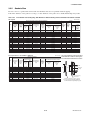
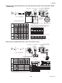
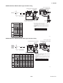
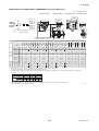
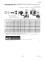
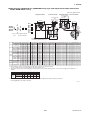
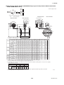
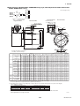
3.3.3
Nominal Diameter 50 mm (2.0
in.) to 300 mm (12.0 in.), Wafer
Type
(3) Positioning the Flowmeter
Position the flowmeter so that the Mini-flanges and the
centering devices come in close contact with each
other. Be careful to prevent the four centering devices
from coming into contact with the housing. If stud-type
through-bolts are used, position them in such a way
that the four centering devices come in contact with the
bolt threads (refer to Figure 3.3.4). Pass the other
through-bolts through from the process piping side.
IMPORTANT
Use bolts and nuts in compliance with the flange
ratings. When stud-type through-bolts are used,
be sure the outside diameter of the shank is
smaller than that of the thread ridge. Be sure to
choose a gasket with inner and outer diameters
that does not protrude inside the piping (refer to
Table 3.3.16). If the inner diameter of the gasket
is too large, or outer diameter of the gasket is
too small, fluid leakage may result.
NOTE
Precautions for size 125 mm (5 in.), 150 mm
(6 in.), replaceable electrode type
When installing this type of flowmeter with JIS
F12 (JIS 75M) flanges, turn the flowmeter
slightly because the cover of the electrode
chambers will interfere with the bolts.
(1) Mounting Direction
Mount the flowmeter so that the flow direction of the
fluid to be measured is in line with the direction of the
arrow mark on the flowmeter.
(4) Tightening Nuts
Tighten the nuts according to the torque values for
metal piping in Table 3.3.7. For PVC piping, select an
optional code of GA, GC, or GD, use rubber gaskets
and tighten the nuts to the torque values for PVC
piping in Table 3.3.8.
For permeable fluids (such as nitric acid, hydrofluoric
acid, or sodium hydrate at high temperatures), tighten
the nuts according to the torque values in Table 3.3.9.
IMPORTANT
If it is impossible to match the direction of the
arrow mark, the direction of the electrical connection can be changed. Refer to Section 5.1 to
do this properly.
In case the fluid being measured flows against
the arrow direction, refer to the parameter J20:
Flow Direction in the user’s manual of the
AXFA11 Magnetic Flowmeter Remote Converter
(IM 01E20C01-01E) or the AXFA14 Magnetic
Flowmeter Remote Converter/AXF Integral
Flowmeter [Software Edition] (IM 01E20C0201E).
CAUTION
For a flowmeter with fluorocarbon PFA lining, it
is possible that the nuts may loosen as time
passes, so tighten them regularly. Be sure to
tighten the nuts according to the prescribed
torque values. Tighten them diagonally with the
same torque values, step by step up to the
prescribed torque value.
(2) Mounting Centering Devices
To maintain concentricity of the flowmeter with the
pipes, install centering devices. From the process
piping side, pass two through-bolts through the four
centering devices (two for each bolt) and the adjacent
two holes (the lower two holes for horizontal mounting) of both of the flanges (refer to Figure 3.3.4). Use
the appropriate centering devices according to the
nominal diameter and the flange ratings. The centering
devices are engraved with an identifying character. Use
the appropriate ones which meet the required specifications by referring to Table 3.3.10 and Table 3.3.11
(AXF standard models) and Table 3.3.12 (replacement
models for the earlier ADMAG or ADMAG AE).
3-10
IM 01E20D01-01E
3. INSTALLATION
*Nut
*Through-bolt
Piping-side flange
*Gasket
(two units)
*: These items can be ordered optionally.
If they are provided by the user, choose nuts and
bolts in compliance with the flange ratings.
Housing
Miniflange
Horizontal mounting
F0312c.EPS
Centering device
(four units)
F0312a.EPS
Vertical mounting
F0312b.EPS
Figure 3.3.4
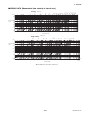
Table 3.3.7
Mounting Procedure for Wafer Type (size: 50 mm (2 in.) to 300 mm (12 in.))
Wafer Type Tightening Torque Values for Metal Piping
Tightening torque values for PFA/Polyurethane Rubber/Natural Soft Rubber/EPDM Rubber lining type
Gasket types
within flowtube
Gasket types
for user’s flange
Flange ratings
Size
mm (inch)
50 (2.0)
65 (2.5)
80 (3.0)
100 (4.0)
125 (5.0)
150 (6.0)
200 (8.0)
250 (10)
300 (12)
N-m
Unit: {kgf-cm}
[in-lbf]
No gasket (standard)
Non-asbestos fiber gasket, PTFE-sheathed non-asbestos gasket
(optional codes BCF and BSF), or the equivalent in hardness
JIS 10K
ANSI Class 150
45.0 to 56.8
{458.9 to 579.2}
[398.3 to 502.7]
61.3 to 70.5
{625.1 to 718.9}
[542.5 to 624.0]
35.0 to 40.3
{356.9 to 410.9}
[309.8 to 356.7]
46.1 to 53
{470.1 to 540.5}
[408.0 to 469.1]
73.7 to 84.8
{751.5 to 864.7}
[652.3 to 750.5]
85.4 to 98.2
{870.8 to 1001}
[755.8 to 869.1]
78.8 to 90.6
{803.5 to 923.9}
[697.4 to 801.8]
119.4 to 137.3
{1218 to 1400}
[1057 to 1215]
83.0 to 99.2
{846.4 to 1012}
[734.6 to 878]
45.0 to 56.8
{458.9 to 579.2}
[398.3 to 502.7]
61.3 to 70.5
{625.1 to 718.9}
[542.5 to 624.0]
76.0 to 80.9
{775.0 to 825.0}
[672.6 to 716.0]
46.1 to 53
{470.1 to 540.5}
[408.0 to 469.1]
73.7 to 84.8
{751.5 to 864.7}
[652.3 to 750.5]
85.4 to 98.2
{870.8 to 1001}
[755.8 to 869.1]
113.6 to 135.8
{1158 to 1385}
[1005 to 1202]
119.4 to 137.3
{1218 to 1400}
[1057 to 1215]
105.2 to 121.0
{1073 to 1234}
[931.1 to 1071]
DIN PN10
—
—
—
—
—
—
113.6 to 135.8
{1158 to 1385}
{1005 to 1202]
119.4 to 137.3
{1218 to 1400}
{1057 to 1215]
105.2 to 121.0
{1073 to 1234}
{931.1 to 1071]
DIN PN16
DIN PN40
JIS F12
(JIS 75M)
—
50.0 to 57.5
{509.9 to 586.3}
[442.5 to 508.9}
—
JIS20K
ANSI Class 300
22.5 to 25.9
{229.4 to 264.1}
[199.1 to 229.2]
30.8 to 35.4
{314.1 to 361.0}
[272.6 to 313.3]
39.9 to 45.9
{406.9 to 468.1}
[353.1 to 406.2]
52.9 to 60.8
{539.4 to 620.0}
[468.2 to 538.1]
80.5 to 92.6
{820.9 to 944.3}
[712.5 to 819.5]
61.0 to 70.2
{622.0 to 715.8}
[539.9 to 621.3]
87.5 to 100.6
{892.3 to 1026}
[774.4 to 890.3]
56.1 to 70.8
{572.1 to 722.0}
[496.5 to 626.6]
39.9 to 45.9
{406.9 to 468.1}
[353.1 to 406.2]
52.9 to 60.8
{539.4 to 620.0}
[468.2 to 538.1]
80.5 to 92.6
{820.9 to 944.3}
[712.5 to 819.5]
91.2 to 96.3
{930.0 to 982.0}
[807.2 to 852.3]
87.5 to 100.6
{892.3 to 1026}
[774.4 to 890.3]
—
—
—
—
—
—
—
—
—
—
—
—
—
—
—
68.4 to 78.7
{697.5 to 802.5}
[605.4 to 696.5]
88.6 to 101.9
{903.5 to 1039}
[784.1 to 901.9]
75.1 to 86.4
{765.8 to 881.0}
[664.7 to 764.7]
86.3 to 99.2
{880.0 to 1012}
[763.8 to 878.0]
88.6 to 101.9
{903.5 to 1039}
[784.1 to 901.9]
158.1 to 181.8
{1612 to 1854}
[1399 to 1609]
146.6 to 168.6
{1495 to 1719}
[1297 to 1492]
N-m
Unit: {kgf-cm}
[in-lbf]
Tightening torque values for Ceramics lining type
Gasket types
Fluororesin with ceramic fillers (Valqua #7020) gasket (standard), or fluororesin with carbon gasket (optional code GF)
within flowtube
Gasket types
Non-asbestos gasket, PTFE-sheathed non-asbestos gasket (optional codes BCF and BSF), or the equivalent in hardness
for user’s flange
Flange ratings
JIS F12
Size
ANSI Class 150
DIN PN10
JIS20K
ANSI Class 300
DIN PN16
DIN PN40
JIS 10K
(JIS 75M)
mm (inch)
50 (2.0)
80 (3.0)
100 (4.0)
150 (6.0)
200 (8.0)
48.2 to 80.3
{491.5 to 818.8}
[426.6 to 710.7]
31.5 to 52.4
{321.2 to 534.3}
[278.8 to 463.8]
36.0 to 59.9
{367.1 to 610.8}
[318.6 to 530.2]
75.5 to 125.9
{769.9 to 1283.8}
[668.2 to 1114.3]
72.9 to 121.6
{743.4 to 1240.0}
[645.2 to 1076.3]
48.6 to 81.0
{495.6 to 826.0}
[430.1 to 716.9]
64.2 to 107.0
{654.7 to 1091.1}
[568.2 to 947.0]
36.3 to 60.4
{370.2 to 615.9}
[321.3 to 534.6]
74.4 to 123.9
{758.7 to 1263.4}
[658.5 to 1096.6]
109.1 to 181.8
{1112.5 to 1853.8}
[965.6 to 1609.1]
—
—
—
—
110.9 to 184.9
{1130.9 to 1885.5}
[981.5 to 1636.5]
23.5 to 39.1
{239.6 to 398.7}
[208.0 to 346.1]
38.8 to 64.7
{395.6 to 659.8}
[343.4 to 572.6]
44.3 to 73.8
{451.7 to 752.6}
[392.1 to 653.2]
53.4 to 89.1
{544.5 to 908.6}
[472.6 to 788.6]
79.0 to 131.6
{805.6 to 1341.9}
[699.2 to 1164.8]
23.7 to 39.5
{241.7 to 402.8}
[209.8 to 349.6]
38.2 to 63.7
{389.5 to 649.6}
[338.1 to 563.8]
43.6 to 72.7
{444.6 to 741.3}
[385.9 to 643.4]
48.8 to 81.3
{497.6 to 829.0}
[431.9 to 719.6]
80.0 to 133.3
{815.8 to 1359.3}
[708.1 to 1179.8]
—
31.5 to 52.4
{321.2 to 534.3}
[278.8 to 463.8]
36.0 to 59.9
{367.1 to 610.8}
[318.6 to 530.2]
75.5 to 125.9
{769.9 to 1283.8}
[668.2 to 1114.3]
72.9 to 121.6
{743.4 to 1240.0}
[645.2 to 1076.3]
48.2 to 80.3
{491.5 to 818.8}
[426.6 to 710.7]
—
—
—
—
—
63.7 to 106.2
{649.6 to 1082.9}
[563.8 to 939.9]
73.0 to 121.6
{744.4 to 1240.0}
[646.1 to 1076.3]
82.3 to 137.1
{839.2 to 1398.0}
[728.4 to 1213.4]
89.7 to 149.5
{914.7 to 1524.5}
[793.9 to 1323.2]
T0308.EPS
3-11
IM 01E20D01-01E
3. INSTALLATION
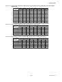
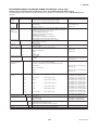
Table 3.3.8
Wafer Type Tightening Torque Values for PVC Piping
N-m
Unit: {kgf-cm}
[in-lbf]
Tightening torque values for PFA lining type
Gasket types
within flowtube
Gasket types
for user’s flange
Fluororubber gasket (optional codes GA, GC, and GD)
Fluororubber gasket, chloroprene rubber gasket (optional codes BSC and BCC), or the equivalent in hardness
Flange ratings
Size
mm (inch)
50 (2.0)
65 (2.5)
80 (3.0)
100 (4.0)
125 (5.0)
150 (6.0)
200 (8.0)
JIS 10K
ANSI Class 150
9.9 to 16.5
{101.0 to 168.3}
[87.6 to 146.0]
14.2 to 23.7
{144.8 to 241.7}
[125.7 to 209.8]
8.0 to 13.3
{81.6 to 135.6}
[70.8 to 117.7]
11.3 to 18.8
{115.2 to 191.7}
[100.0 to 166.4]
18.8 to 31.3
{191.7 to 319.2}
[166.4 to 277.0]
22.5 to 37.6
{229.4 to 383.4}
[199.1 to 332.8]
22.1 to 36.9
{225.4 to 376.3}
[195.6 to 326.6]
9.9 to 16.5
{101.0 to 168.3}
[87.6 to 146.0]
14.2 to 23.7
{144.8 to 241.7}
[125.7 to 209.8]
17.4 to 26.7
{177.4 to 272.3}
[154.0 to 236.3]
11.3 to 18.8
{115.2 to 191.7}
[100.0 to 166.4]
18.8 to 31.3
{191.7 to 319.2}
[166.4 to 277.0]
22.5 to 37.6
{229.4 to 383.4}
[199.1 to 332.8]
31.9 to 55.3
{325.3 to 563.9}
[282.3 to 489.4]
DIN PN10
—
—
—
—
—
—
31.9 to 55.3
{325.3 to 563.9}
[282.3 to 489.4]
JIS20K
ANSI Class 300
10.6 to 17.6
{108.1 to 179.5}
[93.8 to 155.8]
15.5 to 25.9
{158.1 to 264.1}
[137.2 to 229.2]
9.7 to 16.1
{98.9 to 164.2}
[85.8 to 142.5]
14.2 to 23.6
{144.8 to 240.7}
[125.7 to 208.9]
22.3 to 37.2
{227.4 to 379.3}
[197.4 to 329.2]
27.2 to 45.3
{277.4 to 461.9}
[240.7 to 400.9]
27.3 to 45.3
{278.4 to 461.9}
[241.6 to 400.9]
DIN PN16
DIN PN40
JIS F12
(JIS 75M)
—
9.5 to 15.9
{96.9 to 162.1}
[84.1 to 140.7]
—
28.2 to 51.8
{287.6 to 528.2}
[249.6 to 458.4]
9.7 to 16.1
{98.9 to 164.2}
[85.8 to 142.5]
14.2 to 23.6
{144.8 to 240.7}
[125.7 to 208.9]
22.3 to 37.2
{227.4 to 379.3}
[197.4 to 329.2]
40.7 to 62.1
{415.0 to 633.2}
[360.2 to 549.6]
27.3 to 45.3
{278.4 to 461.9}
[241.6 to 400.9]
—
—
—
—
—
—
N-m
Unit: {kgf-cm}
[in-lbf]
Tightening torque values for Ceramics lining type
Gasket types
within flowtube
Gasket types
for user’s flange
Fluororubber gasket (optional codes GA, GC, and GD)
Fluororubber gasket, chloroprene rubber gasket (optional codes BSC and BCC), or the equivalent in hardness
Flange ratings
Size
mm (inch)
50 (2.0)
80 (3.0)
100 (4.0)
150 (6.0)
200 (8.0)
—
15.4 to 25.6
{157.0 to 261.0}
[136.3 to 226.6]
21.1 to 35.1
{215.2 to 357.9}
[186.7 to 310.6]
18.5 to 30.8
{188.6 to 314.1}
[163.7 to 272.6]
21.8 to 36.3
{222.3 to 370.2}
[192.9 to 321.3]
23.8 to 39.6
{242.7 to 403.8}
[210.6 to 350.5]
JIS 10K
ANSI Class 150
6.2 to 10.4
{63.2 to 106.1}
[54.9 to 92.0]
4.4 to 7.3
{44.9 to 74.4}
[38.9 to 64.6]
5.2 to 8.6
{53.0 to 87.7}
[46.0 to 76.1]
10.7 to 17.8
{109.1 to 181.5}
[94.7 to 157.5]
10.2 to 17.1
{104.0 to 174.4}
[90.3 to 151.3]
6.3 to 10.5
{64.2 to 107.1}
[55.8 to 92.9]
10.6 to 17.7
{108.1 to 180.5}
[93.8 to 156.7]
5.7 to 9.5
{58.1 to 96.9}
[50.4 to 84.1]
11.6 to 19.3
{118.3 to 196.8}
[102.7 to 170.8]
18.9 to 31.5
{192.7 to 321.2}
[167.3 to 278.8]
DIN PN10
—
—
—
—
18.7 to 31.2
{190.7 to 318.2}
[165.5 to 276.1]
JIS20K
ANSI Class 300
2.9 to 4.9
{29.6 to 50.0}
[25.7 to 43.4]
5.3 to 8.8
{54.0 to 89.7}
[46.9 to 77.9]
6.0 to 10.0
{61.2 to 102.0}
[53.1 to 88.5]
7.0 to 11.6
{71.4 to 118.3}
[62.0 to 102.7]
10.6 to 17.7
{108.1 to 180.5}
[93.8 to 156.7]
2.9 to 4.9
{29.6 to 50.0}
[25.7 to 43.4]
5.2 to 8.7
{53.0 to 88.7}
[46.0 to 77.0]
6.0 to 10.0
{61.2 to 102.0}
[53.1 to 88.5]
6.6 to 11.0
{67.3 to 112.2}
[58.4 to 97.4]
10.8 to 18.0
{110.1 to 183.5}
[95.6 to 159.3]
DIN PN16
DIN PN40
—
6.2 to 10.4
{63.2 to 106.1}
[54.9 to 92.0]
4.4 to 7.3
{44.9 to 74.4}
[38.9 to 64.6]
5.2 to 8.6
{53.0 to 87.7}
[46.0 to 76.1]
10.7 to 17.8
{109.1 to 181.5}
[94.7 to 157.5]
10.2 to 17.1
{104.0 to 174.4}
[90.3 to 151.3]
—
—
—
—
JIS F12
(JIS 75M)
—
9.6 to 16.0
{97.9 to 163.2}
[85.0 to 141.6]
11.7 to 19.5
{119.3 to 198.8}
[103.6 to 172.6]
13.3 to 22.2
{135.6 to 226.4}
[117.7 to 196.5]
15.3 to 25.5
{156.0 to 260.0}
[135.4 to 225.7]
T0309.EPS
3-12
IM 01E20D01-01E
3. INSTALLATION
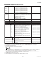
Table 3.3.9
Wafer Type Tightening Torque Values for Metal Piping and Permeable Fluids
N-m
Unit: {kgf-cm}
[in-lbf]
Tightening torque values for PFA lining type
Gasket types
within flowtube
Gasket types
for user’s flange
No gasket (standard)
PTFE-sheathed non-asbestos gasket (optional codes BCF and BSF), or the equivalent in hardness
Flange ratings
Size
mm (inch)
50 (2.0)
65 (2.5)
80 (3.0)
100 (4.0)
125 (5.0)
150 (6.0)
200 (8.0)
250 (10)
300 (12)
JIS 10K
ANSI Class 150
66.2 to 76.1
{675.1 to 776.0}
[585.9 to 673.5]
89.5 to 102.9
{912.6 to 1049}
[792.1 to 910.7]
51.3 to 59.0
{523.1 to 601.6}
[454.0 to 522.2]
66.7 to 76.7
{680.2 to 782.1}
[590.3 to 678.8]
106.1 to 122.0
{1082 to 1244}
[939.0 to 1080]
122.2 to 140.5
{1246 to 1433}
[1082 to 1243]
111.6 to 128.3
{1138 to 1308}
[987.7 to 1136]
167.7 to 192.9
{1710 to 1967}
[1484 to 1707]
115.2 to 137.6
{1175 to 1403}
[1020 to 1218]
66.2 to 76.1
{675.1 to 776.0}
[585.9 to 673.5]
89.5 to 102.9
{912.6 to 1049}
[792.1 to 910.7]
111.3 to 118.4
{1135 to 1207}
[985.0 to 1048]
66.7 to 76.7
{680.2 to 782.1}
[590.3 to 678.8]
106.1 to 122.0
{1082 to 1244}
[939.0 to 1080]
122.2 to 140.5
{1246 to 1433}
[1082 to 1243]
161.0 to 192.3
{1642 to 1961}
[1425 to 1702]
167.7 to 192.9
{1710 to 1967}
[1484 to 1707]
146.0 to 167.9
{1489 to 1712}
[1292 to 1486]
DIN PN10
—
—
—
—
—
—
161.0 to 192.3
{1642 to 1961}
[1425 to 1702]
167.7 to 192.9
{1710 to 1967}
[1484 to 1707]
146.0 to 167.9
{1489 to 1712}
[1292 to 1486]
DIN PN16
DIN PN40
JIS F12
(JIS 75M)
—
71.2 to 118.6
{726.0 to 1209}
[630.1 to 1050]
—
JIS20K
ANSI Class 300
33.1 to 38.0
{337.5 to 387.5}
[292.9 to 336.3]
44.9 to 51.6
{457.9 to 526.2}
[397.4 to 456.7]
58.1 to 66.8
{592.5 to 681.2}
[514.2 to 591.2]
76.1 to 87.5
{776.0 to 892.3}
[673.5 to 774.4]
114.5 to 131.7
{1168 to 1343}
[1013 to 1166]
86.8 to 99.8
{885.1 to 1018}
[768.2 to 883.3]
122.0 to 140.3
{1244 to 1431}
[1080 to 1242]
81.8 to 103.2
{834.1 to 1052}
{724.0 to 913.4]
58.1 to 66.8
{592.5 to 681.2}
{514.2 to 591.2]
76.1 to 87.5
{776.0 to 892.3}
{673.5 to 774.4]
114.5 to 131.7
{1168 to 1343}
{1013 to 1166]
129.8 to 136.9
{1324 to 1396}
{1149 to 1212]
122.0 to 140.3
{1244 to 1431}
{1080 to 1242]
—
—
—
—
—
—
—
—
—
—
100.8 to 115.9
{1028 to 1182}
[892.1 to 1026]
129.8 to 149.3
{1324 to 1522}
[1149 to 1321]
109.6 to 126.0
{1118 to 1285}
[970.0 to 1115]
125.6 to 144.4
{1281 to 1472}
[1112 to 1278]
128.0 to 147.2
{1305 to 1501}
[1133 to 1303]
227.6 to 261.7
{2321 to 2669}
[2014 to 2316]
209.1 to 240.5
{2132 to 2452}
[1851 to 2129]
—
—
—
—
—
N-m
Unit: {kgf-cm}
[in-lbf]
Tightening torque values for Ceramics lining type
Gasket types
within flowtube
Gasket types
for user’s flange
Fluororesin with ceramic fillers (Valqua #7020) gasket (standard), or fluororesin with carbon gasket (optional code GF)
PTFE-sheathed non-asbestos gasket (optional codes BCF and BSF), or the equivalent in hardness
Flange ratings
Size
mm (inch)
50 (2.0)
80 (3.0)
100 (4.0)
150 (6.0)
200 (8.0)
JIS 10K
ANSI Class 150
56.5 to 94.2
{576.1 to 960.6}
[500.1 to 833.7]
37.3 to 62.2
{380.4 to 634.3}
[330.1 to 550.5]
42.2 to 70.3
{430.3 to 716.9}
[373.5 to 622.2]
87.8 to 146.4
{895.3 to 1492.9}
[777.1 to 1295.7]
84.0 to 140.1
{856.6 to 1428.6}
[743.5 to 1240.0]
57.0 to 95.0
{581.2 to 968.7}
[504.5 to 840.8]
76.0 to 126.7
{775.0 to 1292.0}
[672.7 to 1121.4]
42.5 to 70.8
{433.4 to 722.0}
[376.2 to 626.6]
86.4 to 144.0
{881.0 to 1468.4}
[764.7 to 1274.5]
125.4 to 209.1
{1278.7 to 2132.2}
[1109.9 to 1850.7]
DIN PN10
—
—
—
—
127.6 to 212.7
{1301.2 to 2168.9}
[1129.4 to 1882.6]
JIS20K
ANSI Class 300
27.7 to 46.1
{282.5 to 470.1}
[245.2 to 408.0]
46.2 to 77.0
{471.1 to 788.2}
[408.9 to 681.5]
52.0 to 86.7
{530.3 to 884.1}
[460.2 to 767.4]
62.4 to 104.0
{636.3 to 1060.5}
[552.3 to 920.5]
91.1 to 151.9
{929.0 to 1548.9}
[806.3 to 1344.4]
27.9 to 46.5
{284.5 to 474.2}
[246.9 to 411.6]
45.4 to 75.7
{463.0 to 771.9}
[401.8 to 670.0]
51.2 to 85.3
{522.1 to 869.8}
[453.2 to 755.0]
56.8 to 94.7
{579.2 to 965.7}
[502.7 to 838.2]
92.3 to 153.8
{941.3 to 1568.3}
[816.9 to 1361.2]
JIS F12
(JIS 75M)
DIN PN16
DIN PN40
—
56.5 to 94.2
{576.1 to 960.6}
[500.1 to 833.7]
37.3 to 62.2
{380.4 to 634.3}
[330.1 to 550.5]
42.2 to 70.3
{430.3 to 716.9}
[373.5 to 622.2]
87.8 to 146.4
{895.3 to 1492.9}
[777.1 to 1295.7]
84.0 to 140.1
{856.6 to 1428.6}
[743.5 to 1240.0]
—
—
—
—
—
75.5 to 125.8
{769.9 to 1282.8}
[668.2 to 1113.4]
85.4 to 142.3
{870.8 to 1451.1}
[755.9 to 1259.5]
95.4 to 159.0
{972.8 to 1621.3}
[844.4 to 1407.3]
103.0 to 171.7
{1050.3 to 1750.9}
[911.6 to 1519.7]
T0310.EPS
3-13
IM 01E20D01-01E
3. INSTALLATION
Table 3.3.10
Centering Device Identification (AXF Standard Models, PFA/Polyurethane Rubber/Natural Soft Rubber/EPDM
Rubber lining)
Flange
ratings
Size
mm (inch)
10K
20K
F12 (75M)
150
300
PN10
PN16
PN40
50 (2.0)
B
B
—
B
F
—
—
F
65 (2.5)
B
B
—
B
G
—
F
—
80 (3.0)
B
F
H
F
C
—
G
—
100 (4.0)
B
F
H
C
H
—
F
—
125 (5.0)
B
C
C
G
D
—
F
—
150 (6.0)
C
D
D
C
E
—
C
—
200 (8.0)
C
D
D
D
E
C
C
—
250 (10)
C
—
D
N
—
C
C
—
300 (12)
C
—
D
P
—
C
C
—
JIS
DIN
ANSI
*: Each centering device is engraved with a character as identification.
Table 3.3.11
T0311.EPS
Centering Device Identification (AXF Standard Models, Ceramics lining)
Flange
ratings
Size
mm (inch)
10K
20K
F12(75M)
150
300
PN10
PN16
50 (2.0)
B
B
—
B
F
—
—
F
80 (3.0)
B
F
H
F
C
—
G
—
100 (4.0)
B
F
H
C
H
—
F
—
150 (6.0)
B
C
G
B
D
—
B
—
200 (8.0)
B
C
C
G
J
B
B
JIS
DIN
ANSI
—
T0312-1.EPS
*: Each centering device is engraved with a character as identification.
Table 3.3.12
PN40
Centering Device Identification (Replacement Models, PFA/Polyurethane Rubber lining)
Flange
ratings
Size
mm (inch)
10K
20K
F12(75M)
150
300
PN10
PN16
PN40
50 (2.0)
B
B
—
B
F
—
—
F
80 (3.0)
B
F
H
F
C
—
G
—
100 (4.0)
B
F
H
C
H
—
F
—
150 (6.0)
C
D
D
C
E
—
C
—
200 (8.0)
C
D
D
D
E
C
C
JIS
DIN
ANSI
*: Each centering device is engraved with a character as identification.
3-14
—
T0312-2.EPS
IM 01E20D01-01E
3. INSTALLATION
3.3.4
Nominal Diameter 2.5 mm (0.1
in.) to 400 mm (16 in.), Flange
Type
CAUTION
For a flowmeter with fluorocarbon PFA lining, it
is possible that the nuts may loosen as time
passes, so tighten them regularly. Be sure to
tighten the nuts according to the prescribed
torque values. Tighten them diagonally with the
same torque values, step by step up to the
prescribed torque value.
IMPORTANT
Use bolts and nuts in compliance with the flange
ratings. Be sure to choose a gasket with inner
and outer diameters that does not protrude
inside the piping (refer to Table 3.3.16). If the
inner diameter of the gasket is too large, or outer
diameter of the gasket is too small, fluid leakage
may result.
(1) Mounting Direction
Mount the flowmeter so that the flow direction of the
fluid to be measured is in line with the direction of the
arrow mark on the flowmeter.
IMPORTANT
If it is impossible to match the direction of the
arrow mark, the direction of the electrical connection can be changed. Refer to Section 5.1 to
do this properly.
In case the fluid being measured flows against
the arrow direction, refer to the parameter J20:
Flow Direction in the user’s manual of the
AXFA11 Magnetic Flowmeter Remote Converter
(IM 01E20C01-01E) or the AXFA14 Magnetic
Flowmeter Remote Converter/AXF Integral
Flowmeter [Software Edition] (IM 01E20C0201E).
(2) Tightening Nuts
Tighten the bolts according to the torque values for the
metal piping in Table 3.3.13. For PVC piping, select an
optional code of GA, GC, or GD, use rubber gaskets
and tighten the nuts to the torque values for the PVC
piping in Table 3.3.14.
For permeable fluids (such as nitric acid, hydrofluoric
acid, or sodium hydrate at high temperatures), tighten
the nuts according to the torque values in Table 3.3.15.
3-15
IM 01E20D01-01E
3. INSTALLATION
*Piping-side flange
*Gasket (two units)
*: These items must be provided by the user.
Choose nuts and bolts in compliance with
the flange ratings.
Flowmeter-side flange
*Bolt
*Nut
F0313.EPS
Figure 3.3.5
Table 3.3.13
Mounting Procedure for Flange Type (size: 2.5 mm (0.1 in.) to 400 mm (16 in.))
Flange Type Tightening Torque Values for Metal Piping
N-m
Unit: {kgf-cm}
[in-lbf]
Tightening torque values for PFA/Polyurethane Rubber/Natural Soft Rubber/EPDM Rubber lining type
Gasket types
within flowtube
Gasket types
for user’s flange
No gasket (standard)
Non-asbestos gasket, PTFE-sheathed non-asbestos gasket, or the equivalent in hardness
Flange ratings
Size
mm (inch)
2.5 (0.1)
(with 10-mm flanges)
2.5 (0.1)
(with 15-mm flanges)
5 (0.2)
(with 10-mm flanges)
5 (0.2)
(with 15-mm flanges)
10 (0.4)
(with 10-mm flanges)
10 (0.4)
(with 15-mm flanges)
15 (0.5)
25 (1.0)
32 (1.25)
40 (1.5)
50 (2.0)
65 (2.5)
80 (3.0)
100 (4.0)
125 (5.0)
150 (6.0)
200 (8.0)
250 (10)
300 (12)
350 (14)
400 (16)
JIS 10K
ANSI Class 150
3.8 to 6.3
{38.75 to 64.24}
[33.63 to 55.76]
4.6 to 7.7
{46.91 to 78.52}
[40.71 to 68.15]
3.8 to 6.3
{38.75 to 64.24}
[33.63 to 55.76]
4.6 to 7.7
{46.91 to 78.52}
[40.71 to 68.15]
3.8 to 6.3
{38.75 to 64.24}
[33.63 to 55.76]
4.6 to 7.7
{46.91 to 78.52}
[40.71 to 68.15]
4.6 to 7.7
{46.91 to 78.52}
[40.71 to 68.15]
13.1 to 15.1
{133.6 to 154.0}
[115.9 to 133.6]
14.4 to 15.6
{146.8 to 159.1}
[127.4 to138.1]
21.9 to 25.2
{223.3 to 257.0}
[193.8 to 223.0]
28.0 to 32.2
{285.5 to 328.3}
[247.8 to 285.0]
41.6 to 47.8
{424.2 to 487.4}
[368.2 to 423.0]
23.2 to 26.7
{236.6 to 272.3}
[205.3 to 236.3]
30.9 to 35.5
{315.1 to 362.0}
[273.5 to 314.2]
45.6 to 52.4
{465.0 to 534.3}
[403.6 to 463.8]
64.5 to 74.2
{657.7 to 756.6}
[570.8 to 656.7]
59.2 to 68.1
{603.7 to 694.4}
[523.9 to 602.7]
144.0 to 165.6
{1468 to 1689}
[1274 to 1466]
119.3 to 137.2
{1217 to 1399}
[1056 to 1214]
164.7 to 189.4
{1679 to 1931}
[1458 to 1676]
225.2 to 258.9
{2296 to 2640}
[1993 to 2291]
3.8 to 6.3
{38.75 to 64.24}
[33.63 to 55.76]
4.6 to 7.7
{46.91 to 78.52}
[40.71 to 68.15]
3.8 to 6.3
{38.75 to 64.24}
[33.63 to 55.76]
4.6 to 7.7
{46.91 to 78.52}
[40.71 to 68.15]
3.8 to 6.3
{38.75 to 64.24}
[33.63 to 55.76]
4.6 to 7.7
{46.91 to 78.52}
[40.71 to 68.15]
4.6 to 7.7
{46.91 to 78.52}
[40.71 to 68.15]
13.1 to 15.1
{133.6 to 154.0}
[115.9 to 133.6]
14.4 to 15.6
{146.8 to 159.1}
[127.4 to138.1]
21.9 to 25.2
{223.3 to 257.0}
[193.8 to 223.0]
28.0 to 32.2
{285.5 to 328.3}
[247.8 to 285.0]
41.6 to 47.8
{424.2 to 487.4}
[368.2 to 423.0]
52.7 to 53.6
{536.9 to 546.2}
[466.0 to 474.1]
30.9 to 35.5
{315.1 to 362.0}
[273.5 to 314.2]
45.6 to 52.4
{465.0 to 534.3}
[403.6 to 463.8]
64.5 to 74.2
{657.7 to 756.6}
[570.8 to 656.7]
100.3 to 102.1
{1023 to 1041}
[887.8 to 903.3]
144.0 to 165.6
{1468 to 1689}
[1274 to 1466]
163.1 to 197.4
{1663 to 2013}
[1443 to 1747]
256.4 to 293.3
{2615 to 2991}
[2269 to 2596]
225.2 to 258.9
{2296 to 2640}
[1993 to 2291]
DIN PN10
—
—
—
—
—
—
—
—
—
—
—
—
—
—
—
—
100.3 to 102.1
{1023 to 1041}
[887.8 to 903.3]
144.0 to 165.6
{1468 to 1689}
[1274 to 1466]
163.1 to 197.4
{1663 to 2013}
[1443 to 1747]
164.7 to 189.4
{1679 to 1931}
[1458 to 1676]
225.2 to 258.9
{2296 to 2640}
[1993 to 2291]
JIS20K
ANSI Class 300
DIN PN16
3.8 to 6.3
{38.75 to 64.24}
[33.63 to 55.76]
4.7 to 7.8
{47.93 to 79.54}
[41.6 to 69.03]
3.8 to 6.3
{38.75 to 64.24}
[33.63 to 55.76]
4.7 to 7.8
{47.93 to 79.54}
[41.6 to 69.03]
3.8 to 6.3
{38.75 to 64.24}
[33.63 to 55.76]
4.7 to 7.8
{47.93 to 79.54}
[41.6 to 69.03]
4.7 to 7.8
{47.93 to 79.54}
[41.6 to 69.03]
13.2 to 15.2
{134.6 to 155.0}
[116.8 to 134.5]
14.6 to 16.8
{148.9 to 171.3}
[129.2 to 148.7]
22.2 to 25.5
{226.4 to 260.0}
[196.5 to 225.7]
27.8 to 32.0
{283.5 to 326.3}
[246.0 to 283.2]
19.5 to 28.5
{198.8 to 290.6}
[172.6 to 252.2]
26.1 to 30.0
{266.1 to 305.9}
[231.0 to 265.5]
34.8 to 40.0
{354.9 to 407.9}
[308.0 to 354.0]
48.6 to 55.9
{495.6 to 570.0}
[430.1 to 494.7]
44.8 to 51.5
{456.8 to 525.2}
[396.5 to 455.8]
63.6 to 73.1
{648.5 to 745.4}
[562.9 to 647.0]
156.3 to 179.7
{1594 to 1832}
[1383 to 1590]
123.1 to 136.3
{1255 to 1390}
[1089 to 1206]
3.8 to 6.3
{38.75 to 64.24}
[33.63 to 55.76]
4.7 to 7.8
{47.93 to 79.54}
[41.6 to 69.03]
3.8 to 6.3
{38.75 to 64.24}
[33.63 to 55.76]
4.7 to 7.8
{47.93 to 79.54}
[41.6 to 69.03]
3.8 to 6.3
{38.75 to 64.24}
[33.63 to 55.76]
4.7 to 7.8
{47.93 to 79.54}
[41.6 to 69.03]
4.7 to 7.8
{47.93 to 79.54}
[41.6 to 69.03]
13.2 to 15.2
{134.6 to 155.0}
[116.8 to 134.5]
14.6 to 16.8
{148.9 to 171.3}
[129.2 to 148.7]
22.2 to 25.5
{226.4 to 260.0}
[196.5 to 225.7]
27.8 to 32.0
{283.5 to 326.3}
[246.0 to 283.2]
19.5 to 28.5
{198.8 to 290.6}
[172.6 to 252.2]
26.1 to 30.0
{266.1 to 305.9}
[231.0 to 265.5]
34.8 to 40.0
{354.9 to 407.9}
[308.0 to 354.0]
48.6 to 55.9
{495.6 to 570.0}
[430.1 to 494.7]
44.8 to 51.5
{456.8 to 525.2}
[396.5 to 455.8]
63.6 to 73.1
{648.5 to 745.4}
[562.9 to 647.0]
127.2 to 148.8
{1297 to 1517}
[1126 to 1317]
152.3 to 169.4
{1553 to 1727}
[1348 to 1499]
41.4 to 47.6
{422.2 to 485.4}
[366.4 to 421.3]
26.1 to 30.0
{266.1 to 305.9}
[231.0 to 265.5]
34.8 to 40.0
{354.9 to 407.9}
[308.0 to 354.0]
48.6 to 55.9
{495.6 to 570.0}
[430.1 to 494.7]
66.7 to 80.8
{680.2 to 823.9}
[590.3 to 715.1]
63.6 to 73.1
{648.5 to 745.4}
[562.9 to 647.0]
156.3 to 179.7
{1594 to 1832}
[1383 to 1590]
173.3 to 199.3
{1767 to 2032}
[1534 to 1764]
—
—
—
—
—
—
—
—
—
—
—
—
—
—
—
—
—
—
—
DIN PN40
3.8 to 6.4
{38.75 to 65.26}
[33.63 to 56.64]
4.7 to 7.9
{47.93 to 80.56}
[41.6 to 69.92]
3.8 to 6.4
{38.75 to 65.26}
[33.63 to 56.64]
4.7 to 7.9
{47.93 to 80.56}
[41.6 to 69.92]
3.8 to 6.4
{38.75 to 65.26}
[33.63 to 56.64]
4.7 to 7.9
{47.93 to 80.56}
[41.6 to 69.92]
4.7 to 7.9
{47.93 to 80.56}
[41.6 to 69.92]
11.9 to 13.7
{121.3 to 139.7}
[105.3 to 121.3]
15.0 to 17.3
{153.0 to 176.4}
[132.8 to 153.1]
23.2 to 26.7
{236.6 to 272.3}
[205.3 to 236.3]
28.8 to 33.1
{293.7 to 337.5}
[254.9 to 293.0]
—
—
—
—
—
—
—
—
JIS F12
(JIS 75M)
—
—
—
—
—
—
—
—
—
—
—
—
46.0 to 52.9
{469.1 to 539.4}
[407.1 to 468.2]
60.9 to 70.0
{621.0 to 713.8}
[539.0 to 619.5]
48.1 to 55.3
{490.5 to 563.9}
[425.7 to 489.4]
67.5 to 77.6
{688.3 to 791.3}
[597.4 to 686.8]
69.9 to 80.4
{712.8 to 819.9}
[618.6 to 711.6]
190.5 to 219.1
{1943 to 2234}
[1686 to 1939]
168.0 to 193.2
{1713 to 1970}
[1487 to 1710]
238.6 to 274.4
{2433 to 2798}
[2112 to 2429]
305.8 to 351.7
{3118 to 3586}
[2706 to 3113]
T0314.EPS
3-16
IM 01E20D01-01E
3. INSTALLATION
Table 3.3.14
Flange Type Tightening Torque Values for PVC Piping
N-m
Unit: {kgf-cm}
[in-lbf]
Tightening torque values for PFA lining type
Gasket types
within flowtube
Gasket types
for user’s flange
Fluororubber gasket (optional codes GA, GC, and GD)
Fluororubber gasket, chloroprene rubber gasket, or the equivalent in hardness
Flange ratings
Size
mm (inch)
2.5 (0.1)
(with 10-mm flanges)
2.5 (0.1)
(with 15-mm flanges)
5 (0.2)
(with 10-mm flanges)
5 (0.2)
(with 15-mm flanges)
10 (0.4)
(with 10-mm flanges)
10 (0.4)
(with 15-mm flanges)
15 (0.5)
25 (1.0)
32 (1.25)
40 (1.5)
50 (2.0)
65 (2.5)
80 (3.0)
100 (4.0)
125 (5.0)
150 (6.0)
200 (8.0)
JIS 10K
ANSI Class 150
0.8 to 1.3
{8.158 to 13.26}
[7.08 to 11.51]
0.9 to 1.6
{9.177 to 16.32}
[7.966 to 14.16]
0.8 to 1.3
{8.158 to 13.26}
[7.08 to 11.51]
0.9 to 1.6
{9.177 to 16.32}
[7.966 to 14.16]
0.8 to 1.3
{8.158 to 13.26}
[7.08 to 11.51]
0.9 to 1.6
{9.177 to 16.32}
[7.966 to 14.16]
0.9 to 1.6
{9.177 to 16.32}
[7.966 to 14.16]
2.7 to 4.5
{27.53 to 45.89}
[23.9 to 39.83]
3.0 to 4.9
{30.59 to 49.97}
[26.55 to 43.37]
4.5 to 7.6
{45.89 to 77.5}
[39.83 to 67.26]
5.9 to 9.8
{60.16 to 99.93}
[52.22 to 86.74]
9.0 to 15.0
{91.8 to 153.0}
[79.7 to 132.8]
4.9 to 8.1
{50.0 to 82.6}
[43.4 to 71.7]
6.7 to 11.2
{68.3 to 114.2}
[59.3 to 99.1]
9.9 to 16.5
{101.0 to 168.3}
[87.6 to 146.0]
14.4 to 24.0
{146.8 to 244.7}
[127.4 to 212.4]
13.4 to 22.3
{136.6 to 227.4}
[118.6 to 197.4]
0.8 to 1.3
{8.158 to 13.26}
[7.08 to 11.51]
0.9 to 1.6
{9.177 to 16.32}
[7.966 to 14.16]
0.8 to 1.3
{8.158 to 13.26}
[7.08 to 11.51]
0.9 to 1.6
{9.177 to 16.32}
[7.966 to 14.16]
0.8 to 1.3
{8.158 to 13.26}
[7.08 to 11.51]
0.9 to 1.6
{9.177 to 16.32}
[7.966 to 14.16]
0.9 to 1.6
{9.177 to 16.32}
[7.966 to 14.16]
2.7 to 4.5
{27.53 to 45.89}
[23.9 to 39.83]
3.0 to 4.9
{30.59 to 49.97}
[26.55 to 43.37]
4.5 to 7.6
{45.89 to 77.5}
[39.83 to 67.26]
5.9 to 9.8
{60.16 to 99.93}
[52.22 to 86.74]
9.0 to 15.0
{91.8 to 153.0}
[79.7 to 132.8]
11.1 to 16.3
{113.2 to 166.2}
[98.2 to 144.3]
6.7 to 11.2
{68.3 to 114.2}
[59.3 to 99.1]
9.9 to 16.5
{101.0 to 168.3}
[87.6 to 146.0]
14.4 to 24.0
{146.8 to 244.7}
[127.4 to 212.4]
22.7 to 33.4
{231.5 to 340.6}
[200.9 to 295.6]
DIN PN10
—
—
—
—
—
—
—
—
—
—
—
—
—
—
—
—
22.7 to 33.4
{231.5 to 340.6}
[200.9 to 295.6]
JIS20K
ANSI Class 300
0.8 to 1.3
{8.158 to 13.26}
[7.08 to 11.51]
0.9 to 1.6
{9.177 to 16.32}
[7.966 to 14.16]
0.8 to 1.3
{8.158 to 13.26}
[7.08 to 11.51]
0.9 to 1.6
{9.177 to 16.32}
[7.966 to 14.16]
0.8 to 1.3
{8.158 to 13.26}
[7.08 to 11.51]
0.9 to 1.6
{9.177 to 16.32}
[7.966 to 14.16]
0.9 to 1.6
{9.177 to 16.32}
[7.966 to 14.16]
2.7 to 4.5
{27.53 to 45.89}
[23.9 to 39.83]
3.0 to 5.0
{30.59 to 50.99}
[26.55 to 44.25]
4.7 to 7.8
{47.93 to 79.54}
[41.6 to 69.03]
2.9 to 4.8
{29.57 to 48.95 }
[25.67 to 42.48]
2.1 to 4.4
{21.4 to 44.9}
[18.6 to 38.9]
5.5 to 9.1
{56.1 to 92.8}
[48.7 to 80.5]
7.5 to 12.6
{76.5 to 128.5}
[66.4 to 111.5]
10.7 to 17.8
{109.1 to 181.5}
[94.7 to 157.5]
9.8 to 16.3
{99.9 to 166.2}
[86.7 to 144.3]
14.6 to 24.3
{148.9 to 247.8}
[129.2 to 215.1]
0.8 to 1.3
{8.158 to 13.26}
[7.08 to 11.51]
0.9 to 1.6
{9.177 to 16.32}
[7.966 to 14.16]
0.8 to 1.3
{8.158 to 13.26}
[7.08 to 11.51]
0.9 to 1.6
{9.177 to 16.32}
[7.966 to 14.16]
0.8 to 1.3
{8.158 to 13.26}
[7.08 to 11.51]
0.9 to 1.6
{9.177 to 16.32}
[7.966 to 14.16]
0.9 to 1.6
{9.177 to 16.32}
[7.966 to 14.16]
2.7 to 4.5
{27.53 to 45.89}
[23.9 to 39.83]
3.0 to 5.0
{30.59 to 50.99}
[26.55 to 44.25]
4.7 to 7.8
{47.93 to 79.54}
[41.6 to 69.03]
2.9 to 4.8
{29.57 to 48.95 }
[25.67 to 42.48]
2.1 to 4.4
{21.4 to 44.9}
[18.6 to 38.9]
5.5 to 9.1
{56.1 to 92.8}
[48.7 to 80.5]
7.5 to 12.6
{76.5 to 128.5}
[66.4 to 111.5]
10.7 to 17.8
{109.1 to 181.5}
[94.7 to 157.5]
9.8 to 16.3
{99.9 to 166.2}
[86.7 to 144.3]
14.6 to 24.3
{148.9 to 247.8}
[129.2 to 215.1]
DIN PN16
—
—
—
—
—
—
—
—
—
—
—
4.4 to 7.3
{44.9 to 74.4}
[38.9 to 64.6]
5.5 to 9.1
{56.1 to 92.8}
[48.7 to 80.5]
7.5 to 12.6
{76.5 to 128.5}
[66.4 to 111.5]
10.7 to 17.8
{109.1 to 181.5}
[94.7 to 157.5]
14.6 to 25.6
{148.9 to 261.0}
[129.2 to 226.6]
14.6 to 24.3
{148.9 to 247.8}
[129.2 to 215.1]
DIN PN40
0.8 to 1.3
{8.158 to 13.26}
[7.08 to 11.51]
0.9 to 1.6
{9.177 to 16.32}
[7.966 to 14.16]
0.8 to 1.3
{8.158 to 13.26}
[7.08 to 11.51]
0.9 to 1.6
{9.177 to 16.32}
[7.966 to 14.16]
0.8 to 1.3
{8.158 to 13.26}
[7.08 to 11.51]
0.9 to 1.6
{9.177 to 16.32}
[7.966 to 14.16]
0.9 to 1.6
{9.177 to 16.32}
[7.966 to 14.16]
2.3 to 3.9
{23.45 to 39.77}
[20.36 to 34.52]
2.9 to 4.9
{29.57 to 49.97}
[25.67 to 43.37]
4.4 to 7.4
{44.87 to 75.46}
[38.94 to 65.49]
5.5 to 9.2
{56.08 to 93.81 }
[48.68 to 81.43]
—
—
—
—
—
—
JIS F12
(JIS 75M)
—
—
—
—
—
—
—
—
—
—
—
—
9.7 to 12.2
{98.9 to 124.4}
[85.8 to 108.0]
13.3 to 22.2
{135.6 to 226.4}
[117.7 to 196.5]
10.5 to 17.6
{107.1 to 179.5}
[92.9 to 155.8]
15.2 to 25.3
{155.0 to 258.0}
[134.5 to 223.9]
16.1 to 26.9
{164.2 to 274.3}
[142.5 to 238.1]
T0315.EPS
3-17
IM 01E20D01-01E
3. INSTALLATION
Table 3.3.15
Flange Type Tightening Torque Values for Metal Piping and Permeable Fluids
N-m
Unit: {kgf-cm}
[in-lbf]
Tightening torque values for PFA lining type
Gasket types
within flowtube
Gasket types
for user’s flange
No gasket (standard)
Non-asbestos gasket, PTFE-sheathed non-asbestos gasket, or the equivalent in hardness
Flange ratings
Size
mm (inch)
2.5 (0.1)
(with 10-mm flanges)
2.5 (0.1)
(with 15-mm flanges)
5 (0.2)
(with 10-mm flanges)
5 (0.2)
(with 15-mm flanges)
10 (0.4)
(with 10-mm flanges)
10 (0.4)
(with 15-mm flanges)
15 (0.5)
25 (1.0)
32 (1.25)
40 (1.5)
50 (2.0)
65 (2.5)
80 (3.0)
100 (4.0)
125 (5.0)
150 (6.0)
200 (8.0)
250 (10)
300 (12)
350 (14)
400 (16)
JIS 10K
ANSI Class 150
5.7 to 6.6
{58.12 to 67.3}
[50.45 to 58.41]
6.9 to 7.9
{70.36 to 80.56}
[61.07 to 69.92]
5.7 to 6.6
{58.12 to 67.3}
[50.45 to 58.41]
6.9 to 7.9
{70.36 to 80.56}
[61.07 to 69.92]
5.7 to 6.6
{58.12 to 67.3}
[50.45 to 58.41]
6.9 to 7.9
{70.36 to 80.56}
[61.07 to 69.92]
6.9 to 7.9
{70.36 to 80.56}
[61.07 to 69.92]
19.6 to 22.5
{199.9 to 229.4}
[173.5 to 199.1]
21.5 to 24.7
{219.2 to 251.9}
[190.3 to 218.6]
32.5 to 37.4
{331.4 to 381.4}
[287.6 to 331.0]
41.3 to 47.5
{421.1 to 484.4}
[365.5 to 420.4]
61.2 to 70.4
{624.1 to 717.9}
[541.6 to 623.1]
34.2 to 39.3
{348.7 to 400.7}
[302.7 to 347.8]
45.2 to 52.0
{460.9 to 530.3}
[400.0 to 460.2]
66.8 to 76.8
{681.2 to 783.1}
[591.2 to 679.7]
93.9 to 108.8
{957.5 to 1109}
[831.1 to 962.9]
85.8 to 98.7
{874.9 to 1006}
[759.4 to 873.5]
207.8 to 239.0
{2119 to 2437}
[1839 to 2115]
171.0 to 196.7
{1744 to 2006}
[1513 to 1741]
234.7 to 269.9
{2393 to 2752}
[2077 to 2389]
320.0 to 368.0
{3263 to 3753}
[2832 to 3257]
5.7 to 6.6
{58.12 to 67.3}
[50.45 to 58.41]
6.9 to 7.9
{70.36 to 80.56}
[61.07 to 69.92]
5.7 to 6.6
{58.12 to 67.3}
[50.45 to 58.41]
6.9 to 7.9
{70.36 to 80.56}
[61.07 to 69.92]
5.7 to 6.6
{58.12 to 67.3}
[50.45 to 58.41]
6.9 to 7.9
{70.36 to 80.56}
[61.07 to 69.92]
6.9 to 7.9
{70.36 to 80.56}
[61.07 to 69.92]
19.6 to 22.5
{199.9 to 229.4}
[173.5 to 199.1]
21.5 to 24.7
{219.2 to 251.9}
[190.3 to 218.6]
32.5 to 37.4
{331.4 to 381.4}
[287.6 to 331.0]
41.3 to 47.5
{421.1 to 484.4}
[365.5 to 420.4]
61.2 to 70.4
{624.1 to 717.9}
[541.6 to 623.1]
77.6 to 78.8
{791.3 to 803.5}
[686.8 to 697.4]
45.2 to 52.0
{460.9 to 530.3}
[400.0 to 460.2]
66.8 to 76.8
{681.2 to 783.1}
[591.2 to 679.7]
93.9 to 108.8
{957.5 to 1109}
[831.1 to 962.9]
145.4 to 147.9
{1483 to 1508}
[1287 to 1309]
207.8 to 239.0
{2119 to 2437}
[1839 to 2115]
233.7 to 283.0
{2383 to 2886}
[2068 to 2505]
365.4 to 418.0
{3726 to 4262}
[3234 to 3699]
320.0 to 368.0
{3263 to 3753}
[2832 to 3257]
DIN PN10
—
—
—
—
—
—
—
—
—
—
—
—
—
—
—
—
145.4 to 147.9
{1483 to 1508}
{1287 to 1309]
207.8 to 239.0
{2119 to 2437}
{1839 to 2115]
233.7 to 283.0
{2383 to 2886}
{2068 to 2505]
234.7 to 269.9
{2393 to 2752}
{2077 to 2389]
320.0 to 368.0
{3263 to 3753}
{2832 to 3257]
JIS20K
ANSI Class 300
5.7 to 6.6
{58.12 to 67.3}
[50.45 to 58.41]
7.0 to 8.1
{71.38 to 82.6}
[61.95 to 71.69]
5.7 to 6.6
{58.12 to 67.3}
[50.45 to 58.41]
7.0 to 8.1
{71.38 to 82.6}
[61.95 to 71.69]
5.7 to 6.6
{58.12 to 67.3}
[50.45 to 58.41]
7.0 to 8.1
{71.38 to 82.6}
[61.95 to 71.69]
7.0 to 8.1
{71.38 to 82.6}
[61.95 to 71.69]
19.7 to 22.7
{200.9 to 231.5}
[174.4 to 200.9]
21.6 to 24.8
{220.3 to 252.9}
[191.2 to 219.5]
32.8 to 37.7
{334.5 to 384.4}
[290.3 to 333.7]
20.6 to 23.7
{210.1 to 241.7}
[182.3 to 209.8]
14.3 to 21.0
{145.8 to 214.1}
[126.6 to 185.9]
38.5 to 44.3
{392.6 to 451.7}
[340.7 to 392.1]
51.0 to 58.7
{520.1 to 598.6}
[451.4 to 519.5]
70.8 to 81.4
{722.0 to 830.1}
[626.6 to 720.4]
65.4 to 75.2
{666.9 to 766.8}
[578.8 to 665.5]
91.5 to 105.2
{933.0 to 1073}
[809.8 to 931.1]
222.9 to 256.3
{2273 to 2614}
[1973 to 2268]
130.7 to 144.8
{1333 to 1477}
[1157 to 1282]
5.7 to 6.6
{58.12 to 67.3}
[50.45 to 58.41]
7.0 to 8.1
{71.38 to 82.6}
[61.95 to 71.69]
5.7 to 6.6
{58.12 to 67.3}
[50.45 to 58.41]
7.0 to 8.1
{71.38 to 82.6}
[61.95 to 71.69]
5.7 to 6.6
{58.12 to 67.3}
[50.45 to 58.41]
7.0 to 8.1
{71.38 to 82.6}
[61.95 to 71.69]
7.0 to 8.1
{71.38 to 82.6}
[61.95 to 71.69]
19.7 to 22.7
{200.9 to 231.5}
[174.4 to 200.9]
21.6 to 24.8
{220.3 to 252.9}
[191.2 to 219.5]
32.8 to 37.7
{334.5 to 384.4}
[290.3 to 333.7]
20.6 to 23.7
{210.1 to 241.7}
[182.3 to 209.8]
14.3 to 21.0
{145.8 to 214.1}
[126.6 to 185.9]
38.5 to 44.3
{392.6 to 451.7}
[340.7 to 392.1]
51.0 to 58.7
{520.1 to 598.6}
[451.4 to 519.5]
70.8 to 81.4
{722.0 to 830.1}
[626.6 to 720.4]
65.4 to 75.2
{666.9 to 766.8}
[578.8 to 665.5]
91.5 to 105.2
{933.0 to 1073}
[809.8 to 931.1]
181.4 to 212.2
{1850 to 2164}
[1605 to 1878]
161.8 to 180.0
{1650 to 1835}
[1432 to 1593]
DIN PN16
30.5 to 35.1
{311.0 to 357.9}
[269.9 to 310.6]
38.5 to 44.3
{392.6 to 451.7}
[340.7 to 392.1]
51.0 to 58.7
{520.1 to 598.6}
[451.4 to 519.5]
70.8 to 81.4
{722.0 to 830.1}
[626.6 to 720.4]
97.3 to 118.0
{992.2 to 1203}
[861.1 to 1044]
91.5 to 105.2
{933.0 to 1073}
[809.8 to 931.1]
222.9 to 256.3
{2273 to 2614}
[1973 to 2268]
184.1 to 211.7
{1877 to 2159}
[1629 to 1874]
—
—
—
—
—
—
—
—
—
—
—
—
—
—
—
—
—
—
—
DIN PN40
5.7 to 6.6
{58.12 to 67.3}
[50.45 to 58.41]
7.0 to 8.1
{71.38 to 82.6}
[61.95 to 71.69]
5.7 to 6.6
{58.12 to 67.3}
[50.45 to 58.41]
7.0 to 8.1
{71.38 to 82.6}
[61.95 to 71.69]
5.7 to 6.6
{58.12 to 67.3}
[50.45 to 58.41]
7.0 to 8.1
{71.38 to 82.6}
[61.95 to 71.69]
7.0 to 8.1
{71.38 to 82.6}
[61.95 to 71.69]
17.5 to 20.1
{178.5 to 205.0}
[154.9 to 177.9]
22.1 to 25.4
{225.4 to 259.0}
[195.6 to 224.8]
33.8 to 38.9
{344.7 to 396.7}
[229.2 to 344.3]
42.2 to 48.5
{430.3 to 494.6}
[373.5 to 429.3]
—
—
—
—
—
—
—
—
JIS F12
(JIS 75M)
—
—
—
—
—
—
—
—
—
—
—
—
68.1 to 78.3
{694.4 to 798.4}
[602.7 to 693.0]
89.6 to 103.0
{913.7 to 1050}
[793.0 to 911.6]
70.7 to 81.3
{720.9 to 829.0}
[625.7 to 719.5]
98.8 to 113.6
{1007 to 1158}
[874.4 to 1005]
101.8 to 117.1
{1038 to 1194}
[901.0 to 1036]
277.9 to 319.6
{2834 to 3259}
[2460 to 2829]
243.8 to 280.4
{2486 to 2859}
[2158 to 2482]
350.6 to 403.2
{3575 to 4112}
[3103 to 3568]
448.3 to 515.5
{4571 to 5257}
[3968 to 4562]
T0316.EPS
3-18
IM 01E20D01-01E
3. INSTALLATION
3.3.5
Gaskets Size
Be sure to choose a gasket with an inner and outer diameter that does not protrude inside the piping.
If the inner diameter of the gasket is too large, or outer diameter of the gasket is too small, fluid leakage may result.
Table 3.3.16
Inner Diameter of Grounding Ring, Outer Diameter for Effective Sealing and Recommended Inner Diameter of Gasket
AXF Standard:
Unit : mm (in.)
PFA/ Polyurethane Rubber/ Natural Soft Rubber/ EPDM Rubber
Flange
Water
Recommended Inner
Diameter of Gasket
Size
Inner Diameter Outer Diameter
PTFEof Grounding
for Effective
sheathed
Ring
Sealing
Flat Gasket
Non[øA]
[øB]
[øC]
asbestos
Gasket
[øD]
Ceramics
Recommended Inner Diameter of Gasket
Inner Diameter of
Grounding Ring
[øA]
Outer
Diameter
for Effective
Sealing
[øB]
Flat Gasket
[øC]
PTFE-sheathed
Non-asbestos
Gasket
[øD]
Outer
Inner
Diameter of Diameter for
Effective
Grounding
Sealing
Ring
[øB]
[øA]
Recommended Inner
Diameter of Gasket
PTFEsheathed
Nonasbestos
Gasket
[øD]
Flat Gasket
[øC]
2.5 (0.1)
15 (0.59)
38 (1.50)
17 (0.67)
22 (0.87)
15 (0.59) [12 (0.47)] *1
30 (1.18)
17 (0.67) [15 (0.59)]*1
22 (0.87) [19 (0.75)]*1
–
–
–
5 (0.2)
15 (0.59)
38 (1.50)
17 (0.67)
22 (0.87)
15 (0.59) [12 (0.47)] *1
30 (1.18)
17 (0.67) [15 (0.59)]*1
22 (0.87) [19 (0.75)]*1
–
–
–
10 (0.4)
15 (0.59)
38 (1.50)
17 (0.67)
22 (0.87)
15 (0.59) [12 (0.47)] *1
30 (1.18)
17 (0.67) [15 (0.59)]*1
22 (0.87) [19 (0.75)]*1
–
–
–
15 (0.5)
15 (0.59)
38 (1.50)
22 (0.87)
15 (0.59)
34 (1.34)
22 (0.87)
15 (0.59)
33 (1.30)
22 (0.87)
35 (1.38)
25 (1.0)
28 (1.10)
53 (2.09)
35 (1.38)
28 (1.10)
53 (2.09)
35 (1.38)
27 (1.06)
50 (1.97)
32 (1.25)
34 (1.34)
58 (2.28)
43 (1.69)
34 (1.34)
58 (2.28)
43 (1.69)
–
–
–
40 (1.5)
41 (1.61)
71 (2.80)
49 (1.93)
41 (1.61)
71 (2.80)
49 (1.93)
40 (1.57)
68 (2.68)
49 (1.93)
50 (2.0)
53 (2.09)
84 (3.31)
61 (2.40)
53 (2.09)
84 (3.31)
61 (2.40)
52 (2.05)
82 (3.23)
61 (2.40)
65 (2.5)
66 (2.60)
103 (4.06)
84 (3.31)
66 (2.60)
103 (4.06)
84 (3.31)
–
–
–
80 (3.0)
77 (3.03)
114 (4.49)
90 (3.54)
77 (3.03)
114 (4.49)
90 (3.54)
81 (3.19)
112 (4.41)
90 (3.54)
100 (4.0)
102 (4.02)
140 (5.51)
115 (4.53)
102 (4.02)
140 (5.51)
115 (4.53)
98 (3.86)
134 (5.28)
115 (4.53)
125 (5.0)
128 (5.04)
165 (6.50)
141 (5.55)
128 (5.04)
165 (6.50)
141 (5.55)
–
–
–
150 (6.0)
146.1 (5.75)
190 (7.48)
167 (6.57)
146.1 (5.75)
190 (7.48)
167 (6.57)
144 (5.67)
188 (7.40)
167 (6.57)
200 (8.0)
193.6 (7.62)
240 (9.45)
218 (8.58)
193.6 (7.62)
240 (9.45)
218 (8.58)
192 (7.56)
240 (9.45)
218 (8.58)
250 (10)
243.7 (9.59)
300 (11.81)
270 (10.63)
243 (9.57)
315 (12.40)
270 (10.63)
–
–
–
300 (12)
294.7 (11.60)
348 (13.70)
321 (12.64)
291.3 (11.47)
360 (14.17)
321 (12.64)
–
–
–
350 (14)
–
–
–
323.4 (12.73)
405 (15.94)
359 (14.13)
–
–
–
400 (16)
–
–
–
373.5 (14.70)
465 (18.31)
410 (16.14)
–
–
–
*1: The inner diameter of the process connection code: DD4, DJ, DJ2 is values in brackets [ ].
T25.EPS
Replacement Model for earlier ADMAG or ADMAG AE:
Unit : mm (in.)
PFA/ Polyurethane Rubber
Water
Size
Flange
Recommended Inner
Diameter of Gasket
Inner Diameter Outer Diameter
PTFEof Grounding
for Effective
sheathed
Ring
Sealing
NonFlat Gasket
[øA]
[øB]
asbestos
[øC]
Gasket
[øD]
Size of Inner Diameter of Grounding Ring,
Outer Diameter for Effective Sealing and
Recommended Inner Diameter of Gasket:
Recommended Inner Diameter of Gasket
Inner Diameter of
Grounding Ring
[øA]
Outer
Diameter
for Effective
Sealing
[øB]
PTFE-sheathed
Non-asbestos
Gasket
[øD]
Flat Gasket
[øC]
2.5 (0.1)
15 (0.59)
38 (1.50)
17 (0.67)
22 (0.87)
–
–
–
5 (0.2)
15 (0.59)
38 (1.50)
17 (0.67)
22 (0.87)
–
–
–
10 (0.4)
15 (0.59)
38 (1.50)
17 (0.67)
22 (0.87)
–
–
–
15 (0.5)
15 (0.59)
38 (1.50)
22 (0.87)
–
–
–
25 (1.0)
27 (1.06)
56 (2.20)
35 (1.38)
–
–
–
40 (1.5)
40 (1.57)
71 (2.80)
49 (1.93)
–
–
–
50 (2.0)
52 (2.05)
85 (3.35)
61 (2.40)
–
–
–
80 (3.0)
81 (3.19)
115 (4.53)
90 (3.54)
–
–
–
100 (4.0)
98 (3.86)
144 (5.67)
115 (4.53)
–
–
–
150 (6.0)
140.7 (5.54)
190 (7.48)
167 (6.57)
140.7 (5.54)
205 (8.07)
167 (6.57)
200 (8.0)
188.9 (7.44)
240 (9.45)
218 (8.58)
188.9 (7.44)
255 (10.04)
218 (8.58)
250 (10)
–
–
–
243 (9.57)
315 (12.40)
270 (10.63)
øD *2
øB
AXF
Flowtube
Lining
Grounding Ring
Flat Gasket
PTFE-sheathed Non-asbestos Gasket
T16-3.EPS
3-19
øC øA
*2: Do not have this length be smaller than
the inner diameter of grounding ring (øA).
IM 01E20D01-01E
3. INSTALLATION
3.3.6
Nominal Diameter 15 mm (0.5
in.) to 125 mm (5.0 in.), Sanitary
Type
(2) Mounting Procedure
(a) Clamp type
(process connection codes: HAB, HDB, and HKB)
The sanitary type can be mounted to the piping using a
clamps, a unions, or a welded joints.
1) Welding ferrule
Weld a ferrule to the piping.
IMPORTANT
NOTE
When welding the ferrule, pay attention to the
edge preparation, level differences between the
ferrule and the piping, and the welding current to
avoid deforming the piping or causing stagnation
portion of the fluid.
This section describes the remote flowtube as an
example. The same procedure also applies to
the integral flowmeter.
Sanitary adapters are engraved with character as
identification.
Table 3.3.17
2) Installing gasket
Install a gasket for clamp to fit in the groove on
the ferrule.
Sanitary Adapter Identification
Identification Character
No mark
F
L
FL
Material for Adapter
SUS304
SUSF304
SUS316L
SUSF316L
3) Positioning flowmeter
Position the flowmeter between the two ferrules.
4) Tightening clamp
Install a clamp to cover the tapered parts of the
flowmeter-side adapter and the ferrule, and
tighten the clamp screw.
T3.3.20.EPS
(1) Mounting Direction
Mount the flowmeter so that the flow direction of the
fluid to be measured is in line with the direction of the
arrow mark on the flowmeter.
5) Confirmation of adapter mounting screw
After installation of the magnetic flowmeter, be
sure to retighten the adapter mounting screw
according to Table 3.3.18 or Table 3.3.19.
Be sure to confirm that leakage from adapter
connection point does not occur by filling the
pipe of the flowtube with fluid.
IMPORTANT
If it is impossible to match the direction of the
arrow mark, the direction of the electrical connection can be changed. Refer to Section 5.1 to
do this properly.
In case the fluid being measured flows against
the arrow direction, refer to the parameter J20:
Flow Direction in the user’s manual of the
AXFA11 Magnetic Flowmeter Remote Converter
(IM 01E20C01-01E) or the AXFA14 Magnetic
Flowmeter Remote Converter/AXF Integral
Flowmeter [Software Edition] (IM 01E20C0201E).
NOTE
The ferrule, clamp, and gasket are not provided
with the flowmeter, and must be provided by the
user.
Adapter for clamp connection
Clamp
Gasket
Ferrule
Adapter mounting screw
F0314.EPS
Figure 3.3.6
3-20
Mounting Procedure for Clamp Connection
Type
IM 01E20D01-01E
3. INSTALLATION
(b) Union type
(process connection codes: JDB, JKB, and JSB)
1) Welding sleeve
Pass the piping through a nut and then weld a
sleeve to the piping.
Adapter for union connection
Gasket
IMPORTANT
Sleeve
• Be sure to weld the sleeve after passing the
piping through the nut.
• When welding the sleeve, pay attention to the
edge preparation, level differences between the
sleeve and the piping, and the welding current
to avoid deforming the piping or causing
stagnation of some of the fluid.
Nut
Adapter mounting screw
F0315.EPS
Figure 3.3.7
2) Installing gasket
Install a gasket for union to fit in the groove on
the sleeve.
Mounting Procedure for Union Connection
Type
(c) Butt weld adapter type
(process connection codes: KDB and KKB)
1) Removing adapter
Remove the butt weld adapter by loosening the
mounting screws.
3) Positioning flowmeter
Move the nut closer to the piping temporarily
and position the flowmeter between the two
sleeves.
2) Welding ferrule or sleeve
Weld a ferrule, a sleeve, or an alternative
(provided by the user) to the butt weld adapter.
4) Tightening nut
Install the nut to cover the tapered parts of the
flowmeter-side adapter and the sleeve, and
tighten it using a wrench.
IMPORTANT
• Be sure to weld the ferrule, the sleeve, or the
alternative after removing the butt weld adapter
from the flowmeter itself.
• When welding the ferrule, the sleeve, or the
alternative, pay attention to the edge preparation, level differences between them and the
piping, and the welding current to avoid deforming the piping or causing stagnation portion of
the fluid.
5) Confirmation of adapter mounting screw
After installation of the magnetic flowmeter, be
sure to retighten the adapter mounting screw
according to Table 3.3.18 or Table 3.3.19.
Be sure to confirm that leakage from adapter
connection point does not occur by filling the
pipe of the flowtube with fluid.
NOTE
The sleeve, nut, and gasket are not provided
with the flowmeter, and must be provided by the
user.
3) Installing butt weld adapter
Install a gasket to fit in the groove of the butt
weld adapter, and tighten the mounting screws.
3-21
IM 01E20D01-01E
3. INSTALLATION
CAUTION
• In case of standard gasket (EPDM rubber),
tighten the adapter mounting screw according
to the torque values in Table 3.3.18.
• In case that optional code GH (Silicon rubber)
is selected, tighten the adapter mounting screw
according to the torque values in Table 3.3.19.
• Tighten the adapter mounting screw in diagonal
order step by step.
• After tightening of screw, confirm that gaskets
protrude inside adapter. Protruding of gasket is
necessary to keep the sanitary requirements.
Mini-flange
Gasket
Butt weld adapter
Adapter
mounting screw
F0316.EPS
Table 3.3.18
Figure 3.3.8
Tightening Torque Values of adapter for
EPDM rubber gasket
Mounting Procedure for Weld Joint Adapter
Type
Tightening torque values (N-m / {kgf-cm} / [in-lbf])
(3) Maintenance of Sanitary Type
Refer to Section 5.3.
EPDM rubber
(standard)
15 (0.5), 25 (1.0), 32 (1.25), 40 (1.5) 3.0 to 3.5 / {30.59 to 35.69} / [26.55 to 30.98]
50 (2.0), 65 (2.5)
4.5 to 5.0 / {45.89 to 50.99} / [39.83 to 44.25]
80 (3.0)
8.0 to 9.0 / {81.58 to 91.78} / [70.81 to 79.65]
100 (4.0), 125 (5.0)
10 to 11 / {102.0 to 112.2} / [88.50 to 97.35]
Gasket type
Size mm (inch)
T0502.EPS
Table 3.3.19
Tightening Torque Values of adapter for
silicon rubber gasket
Tightening torque values (N-m / {kgf-cm} / [in-lbf])
Silicon rubber
(optional code GH)
15 (0.5), 25 (1.0), 32 (1.25), 40 (1.5) 2.0 to 2.5 / {20.39 to 25.49} / [17.70 to 22.13]
50 (2.0), 65 (2.5), 80 (3.0)
4.0 to 4.5 / {40.79 to 45.89} / [35.40 to 39.83]
100 (4.0), 125 (5.0)
6.0 to 6.5 / {61.18 to 66.28} / [53.10 to 57.53]
Gasket type
Size mm (inch)
T0503.EPS
4) Mounting flowmeter to piping
Connect the flowmeter to the piping in a manner
appropriate to the ferrule, the sleeve, or the
alternative that has been welded to the adapter.
5) Confirmation of adapter mounting screw
After installation of the magnetic flowmeter, be
sure to retighten the adapter mounting screw
according to Table 3.3.18 or Table 3.3.19.
Be sure to confirm that leakage from adapter
connection point does not occur by filling the
pipe of the flowtube with fluid.
3-22
IM 01E20D01-01E
4. WIRING
4.
WIRING
4.1 Wiring the Integral
Flowmeter
• When waterproof glands or union equipped
waterproof glands are used, avoid tightening
the glands with an excessive torque.
• When the power supply voltage is 24V and
electrical connection is a JIS G1/2 female, it
comes with a blanking plug. Use this plug to
cover the unused wiring port when wiring the
instrument with only one, four-core cable.
• Be sure to turn the power off before opening
the terminal box cover.
• Before turning the power on, tighten the
terminal box cover securely.
• The terminal box cover is locked by the special
screw. In case of opening the terminal box
cover, use the hexagonal wrench attached. For
handling the locking screw, refer to Figure
4.1.5.
• Be sure to lock the cover by the special screw
using the hexagonal wrench attached after
installing the cover. For handling the locking
screw, refer to Figure 4.1.15.
• Explosion protected types must be wired in
accordance with specific requirement (and, in
certain countries, legal regulations) in order to
preserve the effectiveness of their explosion
protected features.
This section describes the wiring of the integral flowmeter.
WARNING
The wiring of the magnetic flowmeter must be
performed by expert engineer or skilled personnel. No operator shall be permitted to perform
procedures relating to wiring.
CAUTION
Once all wiring is complete, check the connections before applying power to the instrument.
Improper arrangements or wiring may cause a
unit malfunction or damage.
4.1.1
Wiring Precautions
Be sure to observe the following precautions when
wiring:
4.1.2
CAUTION
Power Cable/Output Cable
JIS C 3401 control cable equivalent
JIS C 3312 power cable equivalent
14 AWG Belden 8720 equivalent
• In cases where the ambient temperature
exceeds 50°C (122°F), use external heatresistant wiring with a maximum allowable
temperature of 70°C (158°F) or above.
• Do not connect cables outdoors in wet weather
in order to prevent damage from condensation
and to protect the insulation, e.g. inside the
terminal box of the flowmeter.
• All the cable ends must be provided with round
crimp-on terminals and be securely wired.
• The signal cables must be routed in separate
steel conduit tubes 16 (JIS C 8305) or flexible
conduit tubes 15 (JIS C 8309).
• Always route the power and output signal
cables in separate steel conduit tubes, except
when the power supply voltage is 24V and fourcore cables are used for wiring. Keep conduits
or flexible tubes watertight using sealing tape.
Outer Diameter:
With no gland option:
6.5 to 12 mm (0.26 to 0.47 in.)
With gland options EG, EU:
10.5 or 11.5 mm (0.41 to 0.45 in.)
With gland options EP:
6 to 12 mm (0.24 to 0.47 in.)
Nominal Cross Section:
Single wire; 0.5 to 2.5 mm2
Stranded wire; 0.5 to 1.5 mm2
In case of power cable, Green/Yellow covered conductor shall be used only for connection to PROTECTIVE
CONDUCTOR TERMINALS. Conform to IEC227,
IEC245 or equivalent national authorization.
4-1
IM 01E20D01-01E
4. WIRING
For working on the electric wire tubes or the flexible
tubes (G1/2), remove the waterproof gland and attach
them directly to the wiring port.
NOTE
• For power cables, always use a crimp terminal
with an insulation cover.
• Use crimp tools from the manufacturer of the
crimp terminal you want to use to connect the
crimp terminal and cable.
• Use crimp tools that are appropriate for the
diameter of the cable to be connected.
4.1.3
Washer
Wiring Ports
This instrument is of watertight construction as
stipulated in JIS C 0920. It is shipped with a wiring
bracket (waterproof gland or waterproof gland with
union) or a plastic gland attached, only in cases where
an optional specification is selected for the wiring port.
In case of the explosion proof type, refer to Chapter 8.
Gasket
Waterproof gland
Cable
Figure 4.1.1
F0401.EPS
Waterproof Gland (Optional code EG)
IMPORTANT
The wiring port is sealed with a cap (not waterproof). Do not remove the cap from the unused
wiring port. If waterproof property is necessary,
apply a blanking plug to the unused wiring port.
The blanking plug may not be attached depending on the specification. If it is necessary,
contact YOKOGAWA.
Gasket
G1/2
Washer
Tightening gland
(1) When waterproof property is unnecessary
(When there are no particular optional
specifications)
The wiring port is sealed with a cap (not water-proof)
that must be removed before wiring. At this time,
handle the wiring port in accordance with the JIS
C 0920 mentioned above. Do not remove the cap from
the unused wiring port.
Cable
When working on conduit pipes or flexible pipes (G1/2 only)
F0402.EPS
Figure 4.1.2
Waterproof Gland with Union Joint
(Optional code EU)
(2) When waterproof property is necessary
(Wiring using waterproof glands)
Gasket
IMPORTANT
To prevent water or condensation from entering
the converter housing, waterproof glands are
recommended. Do not over-tighten the glands or
damage to the cables may result. Tightness of
the gland can be checked by confirming that the
cable is held firmly in place.
Plastic gland
Figure 4.1.3
4-2
F0403.EPS
Plastic Gland (Optional code EP)
IM 01E20D01-01E
4. WIRING
-
DIO
+
-
D
+
-
I
POWE
SUPPLY
(2) Terminal Configuration
When the cover is removed, the connection terminals
will be visible.
+ L/+ N/ -
(3) Conduit Wiring
When wiring the conduits, pass the conduit through the
wiring connection port, and utilize the waterproof
gland to prevent water from flowing in. Place the
conduit pipe on an angle as shown in Figure 4.1.4.
Install a drain valve at the low end of the vertical pipe,
and open the valve regularly.
Terminal
Label
(Back side)
Drain valve
F0406.EPS
Figure 4.1.6
F0404.EPS
Figure 4.1.4
4.1.4
Terminal Configuration
The description of the terminal symbols is shown in
Table 4.1.1.
Conduit Wiring
For FOUNDATION Fieldbus protocol, please refer to IM
01E20F02-01E.
Wiring Connections
For PROFIBUS PA protocol, please refer to IM
01E20F12-01E.
(1) Removing Cover
Loosen cover locking screw 2 clockwise using a
hexagonal wrench (nominal size 3) to unlock the cover.
(Upon shipment from the manufacturing plant, the
cover is unlocked.) Hold the flowmeter with your hand
and remove the cover by turning it in the direction of
the arrow as shown below.
Table 4.1.1 Terminal Symbols
Terminal
Symbols
Description
Functional grounding
N/L/+
I+
IDO+
DODIO+
DIO-
Power supply
Current output 4 to 20mA DC
Pulse output/Alarm output/
Status output
Alarm output/Status output
Status input
Protective grounding
(Outside of the terminal)
T0401.EPS
(3) Precautions for Wiring of Power Supply
Cables
When connecting to the power supply, observe the
points below. Failure to comply with these warnings
may result in an electric shock or damage to the
instrument.
2
1
Cover locking
screws
F0405.EPS
Figure 4.1.5
Removing the Terminal Box Cover
4-3
IM 01E20D01-01E
4. WIRING
2)
WARNING
Required Power Supply Voltages
IMPORTANT
• Ensure that the power supply is OFF in order to
prevent electric shocks.
• Ensure the protective grounding terminal is
grounded before turning the power on.
• Use insulating sleeve crimp terminals (for 4-mm
screws) for the power supply wiring and protective grounding wiring.
• Install an external switch or circuit breaker as a
means to turn the power off (capacitance; 15A,
conforming to IEC60947-1 and IEC60947-3).
Locate this switch either near the instrument or
in other places facilitating easy operation. Affix
a “Power Off Equipment” label to this external
switch or circuit breaker.
When using a 24 V power supply, the specification for the supply voltage is 24 V (–15% to
+20%), but the input voltage of the converter
drops due to cable resistance therefore it must
be used within the following ranges.
Allowable cable length m(ft)
Supply Voltage and Cable Length
Wiring Procedure
1. Turn the instrument's power off.
2. Wire the power supply cable and the functional
grounding cable to the power supply terminals.
796 (2610)
600 (1970)
446 (1460)
200 ( 660)
0
20.4
22
24
26
28.8
Usable range E (V)
Cable cross section area: 1.25 mm2
Cable cross section area: 2 mm2
F0408.EPS
Functional grounding cable
Setting Power Supply Frequency
IMPORTANT
I
POWE
SUPPLY
+ L/+ N/ -
3)
-
DIO
+
-
D
+
-
Set the local commercial power frequency in
order to eliminate the effect of induction noise
from the power supply.
Refer to “Chapter 6: Parameter Description” in
the user’s manual of the AXF Integral Flowmeter
[Software Edition] (IM 01E20C02-01E).
Parameter No.: J30 and J31
Power supply
cable
F0407.EPS
Figure 4.1.7
Electric Cable Wiring
(4) DC Power Connection
When using DC power as the power supply for the
converter, give attention to the following points.
1)
(5) Grounding
CAUTION
Connecting Power Supply
Be sure to connect the protective grounding of
the AXF integral flowmeter with a cable of 2mm2
or larger cross section in order to avoid electrical
shock to the operators and maintenance engineers and to prevent the influence of external
noise.
Connect the grounding wire to the
mark.
The grounding should satisfy Class D requirements (ground resistance, 100 or less).
In case of TIIS Flameproof type, the grounding
should satisfy Class C requirements (ground
resistance, 10 or less) or class A requirements
(ground resistance, 10 or less).
For explosion proof type except TIIS, follow the
domestic electrical requirements as regulated in
each country.
IMPORTANT
Do not connect power supply with reversed
polarities.
L/+ terminal: connect +
N/– terminal: connect –
IMPORTANT
Do not connect power supply with 100 to 240 V
AC or 100 to 120 V DC in the case of a 24 V
power supply version (power supply code 2).
It will give a damage to the converter.
4-4
IM 01E20D01-01E
4. WIRING
600 V vinyl-insulated cable
(2 mm2 or larger)
IMPORTANT
When optional code A (lighting protector) is
selected, the ground should satisfy Class C
requirements (grounding resistance, 10 or less).
are located
• The protective grounding terminals
on the inside and outside of the terminal area.
Either terminal may be used.
• Use 600 V vinyl insulation wires as the grounding
wires.
grounding ring
• Class D requirements (ground resistance,
100 or less).
Optional code A (lighting protector): Class C
requirements (ground resistance, 10 or less).
• TIIS Flameproof type: Class C requirements
(ground resistance, 10 or less) or class A
requirements (ground resistance, 10 or
less).
• Explosion proof type except TIIS: Domestic
electrical requirements as regulated in each
country.
Protective grounding
terminals
F0409.EPS
Figure 4.1.8
In case grounding rings
are used.
Protective Grounding Terminal Location
In case grounding rings are
not used.
(Available only for metal piping)
F0410.EPS
Figure 4.1.9
IMPORTANT
Improper grounding can have an adverse effect
on the flow measurement. Ensure that the
instrument is properly grounded.
Grounding
(6) Connecting to External Instruments
WARNING
The electromotive force of the magnetic flowmeter is
minute and it is easily affected by noise, and the
reference electric potential is the same as that of the
measuring fluid. Therefore, the reference electric
potential (terminal potential) of the flowtube and
converter also need to be the same as that of the
measuring fluid. Moreover, the potential must be the
same as the ground. The magnetic flowmeter is
equipped with an grounding ring that makes a connection with the charge of the measured fluid for grounding and protects the lining. Be sure to ground the
flowmeter according to Figure 4.1.9.
Before wiring with external instruments, be sure
to turn off the magnetic flowmeter and any
external instruments.
4-5
IM 01E20D01-01E
4. WIRING
Connect the AXF integral flowmeter terminal to
external instruments, giving attention to the following
points. For FOUNDATION Fieldbus protocol, please refer
to IM 01E20F02-01E. For PROFIBUS PA protocol,
please refer to IM 01E20F12-01E.
NOTE
For pulse output from the DO terminals, parameters must be set. Refer to “Parameter Description” in the user’s manual of the AXF Integral
Flowmeter [Software Edition] (IM 01E20C0201E).
4 to 20 mA DC Current Output
AXF integral flowmeter
l+
l-
Protective diode
AXF integral flowmeter DO+
Receiver
Instrument
Mechanical Counter
PULSE OUT
Resistive load max. 750 Ω
DO-
Communication Resistive load
BRAIN
250 to 450 Ω
HART
250 to 600 Ω
AXF integral flowmeter DO+
F0411.EPS
PULSE OUT
Load
Electronic Counter
DO-
Figure 4.1.10 4 to 20 mA DC Output Connection
30V DC, 0.2A. max
F0412.EPS
Pulse Output
Figure 4.1.11 Pulse Output Connection
AXF integral flowmeter
IMPORTANT
• As this is a transistor contact (insulated type),
give attention to proper voltage and polarity
when wiring.
• Do not apply a voltage larger than 30V DC or a
current larger than 0.2A in order to prevent
damage to the instrument.
• When input filter constant of the electronic
counter is large in relation to the pulse width,
the signal will decrease and the count will not
be accurate.
• If the input impedance of the electronic counter
is large, an induction noise from the power
supply may result in inaccurate counts. Use a
shield cable or sufficiently reduce the input
impedance of the electronic counter within the
magnetic flowmeter pulse output specification
range.
• The active pulse output (Optional code EM)
cannot be used in conjunction with the standard
pulse output.
• When the active pulse output (Optional code
EM) is selected, do not be short-circuit between
the DO+ and DO– terminals to avoid damaging
the instrument.
• When the active pulse output (Optional code
EM) is selected, the range of pulse rate must
be set to 2 pps maximum.
• To avoid communication (BRAIN/ HART)
failure, it is recommended to use the shield
cable.
Protective diode
DO+
Mechanical Counter
PULSE OUT DO-
AXF integral flowmeter
DO+
PULSE OUT DO-
Load
Electronic Counter
Output voltage: 24 V DC 20%
Current: 150 mA or less
Pulse rate: 0.0001 to 2 pps
Pulse width: 20, 33, 50, 100 ms
F0413.EPS
Figure 4.1.12 Active Pulse Output Connection
(Optional code EM)
4-6
IM 01E20D01-01E
4. WIRING
Status Input
Protective diode
AXF integral flowmeter DO+ (or DIO+)
IMPORTANT
Load
DO- (or DIO-)
Status inputs are designed for use with novoltage (dry) contacts. Be careful not to connect
the status to any signal source carrying voltage.
Applying voltage may damage the input circuit.
This connection is not possible.
AXF integral flowmeter DO+ (or DIO+)
Relay
Electromagnetic
valve
DO- (or DIO-)
External power supply
30V DC, 0.2A. max
Closed: Less than 200 Ω
Open: More than 100 kΩ
DIO+
AC power supply
AXF integral flowmeter
F0415.EPS
Figure 4.1.14 Status Output/Alarm Output Connection
NOTE
DIONo-voltage status input
For status and alarm outputs from the DO or
DIO terminals, parameters must be set. Refer to
“Parameter Description” in the user’s manual of
the AXF Integral Flowmeter [Software Edition]
(IM 01E20C02-01E).
F0414.EPS
Figure 4.1.13 Status Input Connection
NOTE
For status input to the DIO terminals, parameters
must be set. Refer to “Parameter Description” in
the user’s manual of the AXF Integral Flowmeter
[Software Edition] (IM 01E20C02-01E).
(7) Installing the Cover
Install the cover to the flowmeter by turning it in the
direction of the arrow as shown below. Tighten cover
locking screw 2 counterclockwise using a hexagonal
wrench (nominal size 3) to lock the cover.
Status Output / Alarm Output
IMPORTANT
Since this is an isolated transistor output, be
careful of voltage and polarity when wiring. Do
not apply a voltage larger than 30V DC or a
current larger than 0.2A in order to prevent
damage to the instrument.
This output cannot switch an AC load. To switch
an AC load, an intermediate relay must be
inserted as shown in Figure 4.1.14.
1
2
Cover locking
screws
*The alarm output operates from open (normal) to
closed (alarm occurrence) in the default value (as setup
upon plant shipment). Changes can be made via the
parameter settings.
F0416.EPS
Figure 4.1.15 Installing the Terminal Box Cover
4-7
IM 01E20D01-01E
4. WIRING
4.2 Wiring the Remote
Flowtube
• Ground the remote flowtube and the converter
separately.
• Cover each shield of the signal cable with vinyl
tube or vinyl tape to avoid contact between two
shields or between a shield and a case.
• When waterproof glands or union equipped
waterproof glands are used, avoid tightening
the glands with an excessive torque.
• Be sure to turn the power off before opening
the terminal box cover.
• Before turning the power on, tighten the
terminal box cover securely.
• The terminal box cover is locked by the special
screw. In case of opening the terminal box
cover, use the hexagonal wrench attached. For
handling the locking screw, refer to Figure
4.2.8.
• Be sure to lock the cover by the special screw
using the hexagonal wrench attached after
installing the cover. For handling the locking
screw, refer to Figure 4.2.16.
• Explosion protected types must be wired in
accordance with specific requirement (and, in
certain countries, legal regulations) in order to
preserve the effectiveness of their explosion
protected features.
• When submersible type or optional code DHC
is selected, waterproof glands, signal and
excitation cables are attached.
In order to preserve the effectiveness of
waterproof features, the terminal box cover and
waterproof glands must not be detached from
flowmeter.
This section describes the wiring of the remote
flowtube only. For information relating to the wiring of
the converter, refer to the user’s manual of the
AXFA11 Magnetic Flowmeter Remote Converter (IM
01E20C01-01E) or the AXFA14 Magnetic Flowmeter
Remote Converter (IM 01E20C02-01E).
WARNING
The wiring of the magnetic flowmeter must be
performed by expert engineer or skilled personnel. No operator shall be permitted to perform
procedures relating to wiring.
CAUTION
Once all wiring is complete, check the connections before applying power to the instrument.
Improper arrangements or wiring may cause a
unit malfunction or damage.
4.2.1
Wiring Precautions
Be sure to observe the following precautions when
wiring:
CAUTION
• In cases where the ambient temperature
exceeds 50°C (122°F), use external heatresistant wiring with a maximum allowable
temperature of 70°C (158°F) or above.
• Do not connect cables outdoors in wet weather
in order to prevent damage from condensation
and to protect the insulation, e.g. inside the
terminal box of the flowtube.
• Do not splice the cable between the flowtube
terminal and the converter if it is too short.
Replace the short cable with a cable that is the
appropriate length.
• All the cable ends must be provided with round
crimp-on terminals and be securely wired.
• The signal cables must be routed in separate
steel conduit tubes 16 (JIS C 8305) or flexible
conduit tubes 15 (JIS C 8309).
• Keep conduits or flexible tubes watertight using
sealing tape.
IMPORTANT
Prepare the signal cable and the excitation cable
almost the same length. It is recommended to
lay them together closely.
4-8
IM 01E20D01-01E
4. WIRING
4.2.2
Cables
CAUTION
(1) Dedicated Signal Cable (AXFC)
• As crimp terminals A, B, SA, SB and C have
their own electrical potentials, securely insulate
them so as not to come in contact with one
another.
• To prevent a shield from coming in contact with
another shield or the case, cover each shield
with a vinyl tube or wrap it in vinyl tape.
Conductors (A and B)
Shields (SA and SB)
Tape
Outer jacket
10.5 (0.413")
Shield (C)
Insulation
Insulation
Figure 4.2.1
NOTE
F0417.EPS
Conductors A and B carry the signal from the
electrodes, and C is at the potential of the liquid
(signal common). Shields SA and SB are kept
at the same potentials as the individual electrodes (these are actively driven shields). This is
done to reduce the effect of the distributed
capacitance of the cable at long cable length.
Note that, since the signals from the individual
electrodes are impedance converted inside the
converter, errors will result if they come in
contact with any other component. Great care
must be taken in the cable end treatment.
Dedicated Signal Cable AXFC
The flow signal is transmitted via this dedicated cable.
The cable is constructed with double shielding over the
two conductors, and heat-resistant vinyl is used for the
outer jacket material.
Finished diameter:
10.5 mm (0.413")
Maximum length:
Combination with the AXFA11 converter:
200 m (660 ft)
Combination with the AXFA14 converter:
100 m (330 ft)
Maximum temperature: 80°C (176°F)
(2) Excitation Cable
JIS C 3401 control cable equivalent
JIS C 3312 power cable equivalent
14 AWG Belder 8720 equivalent
IMPORTANT
If the cable is longer than required, cut off any
extra length rather than coiling it up, and terminate the conductors as shown in Figure 4.2.2.
Avoid using junction terminal boards to extend
the cable length, as this will interrupt the shielding.
Outer Diameter:
With no gland option:
6.5 to 12 mm (0.26 to 0.47 in.)
With gland options EG, EU and EW:
10.5 or 11.5 mm (0.41 to 0.45 in.)
With gland options EP:
6 to 12 mm (0.24 to 0.47 in.)
Nominal Cross Section:
Single wire; 0.5 to 2.5 mm2
Stranded wire; 0.5 to 1.5 mm2
B
C
90 (3.54)
90 (3.54)
60 (2.36)
C
70 (2.76)
Black
Red
1505
(5.9)
8 (0.3) max.
L (Specified Dimensions)
20 (0.8)
On the
flowtube
side
10.5 (0.4)
(5.9)
8(0.3) max.
On the
converter
side
White
Red
Black
1505
White
55 (2.17)
A
SB
50 (1.97)
B
A
SA
25 (0.98)
Unit : mm
(approx. inch)
AXFC
F0418.EPS
Figure 4.2.2
Treatment of Dedicated Signal Cables
4-9
IM 01E20D01-01E
4. WIRING
4.2.3
Unit : mm
(approx. inch)
This instrument is of watertight construction as
stipulated in JIS C 0920. It is shipped with a wiring
bracket (waterproof gland or waterproof gland with
union) or a plastic gland attached, only in cases where
an optional specification is selected for the wiring port.
In case of the explosion proof type, refer to Chapter 8.
EX2
EX1
EX2
EX1
Crimp terminal
85 (3.35)
Wiring Ports
85 (3.35)
IMPORTANT
On the converter side
On the flowtube side
The wiring port is sealed with a cap (not waterproof). Do not remove the cap from the unused
wiring port. If waterproof property is necessary
apply a blanking plug to the unused wiring port.
The blanking plug may not be attached depending on the specification. If it is necessary,
contact YOKOGAWA.
F0419.EPS
Figure 4.2.3
End Treatment of Excitation Cable
(1) When waterproof property is unnecessary
(When there are no particular optional
specifications)
The wiring port is sealed with a cap (not water-proof)
that must be removed before wiring. At this time,
handle the wiring port in accordance with the JIS
C 0920 mentioned above. Do not remove the cap from
the unused wiring port.
NOTE
• For excitation cables, always use a crimp
terminal with an insulation cover.
• Use crimp tools from the manufacturer of the
crimp terminal you want to use to connect the
crimp terminal and cable.
• Use crimp tools that are appropriate for the
diameter of the cable to be connected.
(2) When waterproof property is necessary
(Wiring using waterproof glands)
IMPORTANT
To prevent water or condensation from entering
the converter housing, waterproof glands are
recommended. Do not over-tighten the glands or
damage to the cables may result. Tightness of
the gland can be checked by confirming that the
cable is held firmly in place.
For working on the electric wire tubes or the flexible
tubes (G1/2), remove the waterproof gland and attach
them directly to the wiring port.
Washer
Gasket
Waterproof gland
Cable
Figure 4.2.4
4-10
F0420.EPS
Waterproof Gland (Optional code EG)
IM 01E20D01-01E
4. WIRING
4.2.4
Wiring Connections
Gasket
WARNING
Before wiring, be sure that the power supply for
AXFA11 or AXFA14 converter has been turned
off to prevent an electrical shock.
G1/2
Washer
Tightening gland
Cable
(1) Removing Cover
Loosen the cover locking screw clockwise using a
hexagonal wrench (nominal size 3) to unlock the cover.
(Upon shipment from the manufacturing plant, the
cover is unlocked.) Hold the flowtube with your hand
and remove the cover by turning it in the direction of
the arrow as shown below.
When working on conduit pipes or flexible pipes (G1/2 only)
F0421.EPS
Figure 4.2.5
Waterproof Gland with Union Joint
(Optional code EU)
Gasket
Plastic gland
Figure 4.2.6
F0422.EPS
Plastic Gland (Optional code EP)
(3) Conduit Wiring
When wiring the conduits, pass the conduit through the
wiring connection port, and utilize the waterproof
gland to prevent water from flowing in. Place the
conduit pipe on an angle as shown in Figure 4.2.7.
Install a drain valve at the low end of the vertical pipe,
and open the valve regularly.
F0424.EPS
Figure 4.2.8
Removing the Terminal Box Cover (Remote
Flowtube)
(2) Terminal Configuration
When the cover is removed, the connection terminals
will be visible.
Drain valve
Terminal
Symbols
A
B
C
EX1
EX2
F0423.EPS
Figure 4.2.7
Conduit Wiring
Description
Flow signal output
Excitation current input
Protective grounding
(Outside of the terminal)
F0425.EPS
Figure 4.2.9
4-11
Terminal Configuration (General-Purpose
Use, Submersible Type, Sanitary Type)
IM 01E20D01-01E
4. WIRING
Terminal
Symbols
A
B
C
EX1
EX2
(3) Wiring the Remote Flowtube (GeneralPurpose Use, Submersible Type, Sanitary
Type with Converters
Description
1) Connection with the AXFA11 converter
Connect wiring as shown in the figure below.
Flow signal output
Excitation current input
Functional grounding
(Only for explosion proof type)
Protective grounding
(Oitside of the terminal)
I+
I–
CURRENT OUT
SO1+ SO2+ COM
STATUS OUT
N/–
L/+
POWER SUPPLY
EX1
EX2
EXCIT ATION
AL+
AL–
ALARM OUT
C
SA
A
SIGNAL
B
F042401.EPS
SB
AXFA11 converter
FUSE
2.5A 250V
P+
P–
PULSE OUT
SI1+
SI2+
COM
STATUS IN
Figure 4.2.10 Terminal Configuration (Explosion proof
Type)
Excitation cable
AXFC dedicated
signal cable
Converter
A
SA
A
B
SB
C
EX1
EX2
EX2
B
EX1
C
Remote
flowtube
Taping*
A
B
Taping*
C
EX1
EX2
* Individually tape and insulate the
shields corresponding to SA and
SB on the remote flowtube side.
Remote flowtube
F0426.EPS
Figure 4.2.11 Wiring Diagram
2) Connection with the AXFA14 converter
Connect wiring as shown in the figure below.
AXFA14 converter
EX1
EX2
Excitation cable
C
AXFC dedicated
signal cable
SA
A
B
SB
Converter
A
EX2
B
C
EX1
Remote flowtube
SA
A
B
SB
C
EX1
EX2
Remote
flowtube
Taping*
A
B
Taping*
C
EX1
EX2
* Individually tape and insulate the
shields corresponding to SA and
SB on the remote flowtube side.
F0427.EPS
Figure 4.2.12 Wiring Diagram
4-12
IM 01E20D01-01E
4. WIRING
(4) Wiring the Remote Flowtube (Explosion
Proof Type) with Converters
2) Connection with the AXFA14 converter
In case of ATEX, FM, CSA, IECEx or TIIS certified
AXF remote flowtube, connect wiring as shown in the
figure below.
IMPORTANT
In case of the explosion proof type, the protective
grounding
of remote flowtube must be connected to
a suitable IS grounding system. In that case,
(functional grounding terminal) need not be connected.
In case of ATEX, IECEx, or TIIS certified AXF
remote flowtube, it is only approved to be
combined with AXFA14 converter.
AXFA14 converter
1) Connection with the AXFA11 converter
In case of FM or CSA certified AXF remote flowtube,
connect wiring as shown in the figure below.
EX1
EX2
Excitation cable
C
AXFC dedicated
signal cable
In case of the explosion proof type, the protective
grounding
of remote flowtube must be connected to
a suitable IS grounding system. In that case,
(functional grounding terminal) need not be connected.
SA
A
B
SB
Converter
I+
I–
CURRENT OUT
SO1+ SO2+ COM
STATUS OUT
AL+
AL–
ALARM OUT
C
SA
A
SIGNAL
B
SB
N/–
L/+
POWER SUPPLY
EX1
EX2
EXCIT ATION
P+
P–
PULSE OUT
SI1+
AXFC dedicated
signal cable
Converter
A
EX2
C
EX1
Remote flowtube
EX2
B
SI2+
COM
STATUS IN
Excitation cable
B
A
AXFA11 converter
FUSE
2.5A 250V
SA
A
B
SB
C
EX1
EX2
C
EX1
Remote flowtube
Remote
flowtube
Taping*
SA
A
B
SB
C
EX1
EX2
Remote
flowtube
Taping*
A
B
Taping*
C
EX1
EX2
* Individually tape and insulate the
shields corresponding to SA and
SB on the remote flowtube side.
F0429.EPS
A
B
Taping*
C
EX1
EX2
Figure 4.2.14 Wiring Diagram
* Individually tape and insulate the
shields corresponding to SA and
SB on the remote flowtube side.
F0428.EPS
Figure 4.2.13 Wiring Diagram
4-13
IM 01E20D01-01E
4. WIRING
(5) Grounding
600 V vinyl insulated
electric cable
(2 mm2 or larger)
CAUTION
Be sure to connect the protective grounding of
the AXF remote flowtube with a cable of 2mm2
or larger cross section in order to avoid electrical
shock to the operators and maintenance engineers and to prevent the influence of external
noise.
mark.
Connect the grounding wire to the
The grounding should satisfy Class D requirements (ground resistance, 100 or less).
In case of TIIS Flameproof type, the grounding
should satisfy Class C requirements (ground
resistance, 10 or less) or class A requirements
(ground resistance, 10 or less).
For explosion proof type except TIIS, follow the
domestic electrical requirements as regulated in
each country.
Grounding ring
• Class D requirements (ground resistance.
100 or less).
• TIIS Flameproof type: Class C requirements
(ground resistance, 10 or less) or Class A
requirements (ground resistance, 10 or less)
• Explosion proof type except TIIS: Domestic
electrical requirements as regulated in each
country.
IMPORTANT
Improper grounding can have an adverse effect
on the flow measurement. Ensure that the
instrument is properly grounded.
In case grounding rings
are used.
In case grounding rings are
not used.
(Available only for metal piping)
F0430.EPS
The electromotive force of the magnetic flowmeter is
minute and it is easy to be affected by noise. And also
that reference electric potential is the same as the
measuring fluid potential. Therefore, the reference
electric potential (terminal potential) of the flowtube
and the converter also need to be the same as the
measuring fluid. Moreover, that the potential must be
the same with ground. The magnetic flowmeter is
equipped with an grounding ring that makes a connection with the charge of the measured fluid for grounding and protects the lining.
Figure 4.2.15 Protective Grounding Terminal Location
(6) Installing the Cover
Install the cover to the flowtube by turning it in the
direction of the arrow as shown below. Tighten the
cover locking screw counterclockwise using a hexagonal wrench (nominal size 3) to lock the cover.
Be sure to ground according to Figure 4.2.15.
F0431.EPS
Figure 4.2.16 Installing the Terminal Box Cover (Remote
Flowtube)
4-14
IM 01E20D01-01E
5. MAINTENANCE
5.
MAINTENANCE
WARNING
• Maintenance work must be carried out by the
trained personnel having knowledge of safety
standard and not by operators.
• When opening the cover, wait for more than 10
minutes after turning off the power. Furthermore, opening of the cover must also be
carried out by the trained personnel having
knowledge of safety standard.
CAUTION
• Explosion protected type must be, as a rule,
removed to a non-hazardous area for maintenance and be disassembled and reassembled
to the original state.
• The cover is locked by the special screw. In
case of opening the cover, use the hexagonal
wrench attached.
• Be sure to lock the cover by the special screw
using the hexagonal wrench attached after
installing the cover.
F0501.EPS
(4) Using the hexagonal wrench, loosen the screw in
the neck.
(5) Turn the converter or the terminal box in the
desired direction.
NOTE
The converter and the terminal box can be
turned –140 degree to +180 degree from the
arrow mark indicating the flow direction. Do not
exceed these angle.
5.1 Changing Direction of
Electrical Connection
(6) Using the hexagonal wrench, retighten the neck
screw.
IMPORTANT
The following types can not be changed direction
of electrical connection after delivery.
• Submersible Type.
• Optional code DHC (for district heating and
cooling or condensation-proof).
(1) The following tools are required to change the
direction of the electrical connection:
• Hexagonal wrench (nominal size 1.5): Comes
with the instrument.
• Wrench
(2) Turn off the power to the flowmeter.
(3) Using the wrench, loosen the hexagonal nut at the
neck of the instrument.
F0502.EPS
(7) Using the wrench, retighten the hexagonal nut at
the neck. After that, check that the converter or
terminal box is fixed.
5-1
IM 01E20D01-01E
5. MAINTENANCE
5.2 Removing, Cleaning,
and Installing Replaceable Electrodes
(General-Purpose
Use Type Only)
5.2.1
(4) Using end A of the tool, open the electrode cover.
End A
End B
Removing Replaceable Electrodes
(1) The following tools are required to replace the
electrodes:
• Special tool for removing and installing electrodes (F9807SK): Optional
• Torque wrench or torque driver (nominal size 12)
• Phillips screwdriver
F0504.EPS
(5) Hold down the electrode lead wire and terminal
lug and remove the mounting screw using the
Phillips screwdriver.
F9807SK
F0503.EPS
(2) Turn off the power to the flowmeter.
Electrode lead wire:
(3) Drain the fluid from the interior of the flowtube.
Red: Electrode A
White: Electrode B
WARNING
• Never fail to drain the fluid from the interior of
the flowtube.
• If the fluid is at a high temperature, the instrument itself may also be hot. Be careful not to
get burned when removing the electrodes.
• When the process fluid is hazardous to humans, exercise caution to avoid coming into
contact with it, and avoid inhaling any residual
gas.
F0505.EPS
NOTE
Always hold down the lead wire and terminal lug
when removing the mounting screw.
5-2
IM 01E20D01-01E
5. MAINTENANCE
5.2.2
(6) Move aside the electrode lead wire and avoiding
the screw, insert end A of the tool to the electrode
and loosen the electrode holder using the torque
driver.
Cleaning Replaceable Electrodes
(1) Clean the electrode surface (wetted part) with
alcohol or other cleaning agents.
O-ring
Electrode surface
Electrode holde
End A
Torque driver
F0506.EPS
(7) Screw end B of the tool into the screw block of the
electrode, and pull the tool straight out to remove
the electrode holder.
F0508.EPS
NOTE
The screw threads are coated with an antiseizing compound. Do not let the compound
come in contact with the electrode.
(2) Clean the surface of the lining seal with an alcohol
moistened swab.
End B
F0507.EPS
Lining seal surface
F0509.EPS
5-3
IM 01E20D01-01E
5. MAINTENANCE
5.2.3
Installing Replaceable Electrodes
(2) Using end A of the tool, tighten the electrode
holder.
NOTE
It is recommended to replace the O-ring when
reinstalling the replaceable electrode. Use the Oring specified by Yokogawa (G9303SE: material
is fluororubber).
NOTE
Precautions for storage of O-rings:
• Keep them in a cool, dark place.
• Wrap them well.
• Do not use O-rings after one year since their
purchase.
Torque driver
F0511.EPS
NOTE
Using the torque wrench or torque driver, tighten
the electrode holder to the following torque
values:
PFA lining:
8.0 N·m ±1 N·m (80 kgf·cm ±10 kgf·cm)
Polyurethane rubber lining:
3.0 N·m ±0.5 N·m (30 kgf·cm ±5 kgf·cm)
(1) Push the electrode holder with end B of the tool
screwed into it, straight into the flowtube.
Electrode lead wire:
Red: Electrode A
White: Electrode B
WARNING
If the electrode holder was not tightened to its
specified torque value, fluid leakage from the
electrode may result. Should fluid spill over the
electrode block, wipe it dry and check that the
O-ring has not come off.
Electrode holder:
(Electrode A is engraved with "A"
and electrode B has no markings.)
F0510.EPS
(3) Fill the interior of the flowtube with the fluid and
check that there is no leakage from the electrode.
NOTE
(4) Hold down the lead wire and terminal lug and
screw the mounting screw into the electrode using
the Phillips screwdriver.
• Check that the O-ring has not come off.
• Do not interchange electrodes A and B when
installing them. Install electrode A to the
electrode boss with the red lead wire and
electrode B to the one with the white lead wire.
Electrode mounting screw
F0512.EPS
5-4
IM 01E20D01-01E
5. MAINTENANCE
2) Installing the butt weld adapter
NOTE
Install a gasket to fit in the groove of the butt weld
adapter, and tighten in the adapter with the
mounting screws.
Always hold down the lead wire and terminal lug
when adjusting the mounting screw.
(5) Put the lead wire in the electrode boss, and install
the electrode cover to the boss and tighten it using
end A of the tool.
Mini-flange
Gasket
Butt weld adapter
Adapter
mounting screw
Electrode boss
F0316.EPS
Figure 5.3.1
Torque driver
Removing and Installing a Butt Weld
Adapter
F0513.EPS
CAUTION
(6) Turn on the power to the flowmeter and start
normal operation.
• In case of standard gasket (EPDM rubber),
tighten the adapter mounting screw according
to the torque values in Table 5.3.1.
• In case that optional code GH (Silicon rubber)
is selected, tighten the adapter mounting screw
according to the torque values in Table 5.3.2.
• Tighten the adapter mounting screw in diagonal
order step by step.
• After tightening of screw, confirm that gaskets
protrude inside adapter. Protruding of gasket is
necessary to keep the sanitary requirements.
5.3 Removing and Installing Adapters for
Sanitary Types
CAUTION
• This section describes how to remove and
install a butt weld adapter as an example.
Apply the same procedure to clamp and union
adapters.
• Turn off the power of the magnetic flowmeter,
and confirm that there is no fluid inside the pipe
before removing the instrument from the pipe
line.
• When installation, refer to Subsection 3.3.6.
Table 5.3.1
Tightening Torque Values of adapter for
EPDM rubber gasket
Tightening torque values (N-m / {kgf-cm} / [in-lbf])
EPDM rubber
(standard)
15 (0.5), 25 (1.0), 32 (1.25), 40 (1.5) 3.0 to 3.5 / {30.59 to 35.69} / [26.55 to 30.98]
50 (2.0), 65 (2.5)
4.5 to 5.0 / {45.89 to 50.99} / [39.83 to 44.25]
80 (3.0)
8.0 to 9.0 / {81.58 to 91.78} / [70.81 to 79.65]
100 (4.0), 125 (5.0)
10 to 11 / {102.0 to 112.2} / [88.50 to 97.35]
Gasket type
Size mm (inch)
T0502.EPS
Table 5.3.2
1) Removing the butt weld adapter
Tightening Torque Values of adapter for
silicon rubber gasket
Tightening torque values (N-m / {kgf-cm} / [in-lbf])
Remove the butt weld adapter by loosening the
mounting screws.
Silicon rubber
(optional code GH)
15 (0.5), 25 (1.0), 32 (1.25), 40 (1.5) 2.0 to 2.5 / {20.39 to 25.49} / [17.70 to 22.13]
50 (2.0), 65 (2.5), 80 (3.0)
4.0 to 4.5 / {40.79 to 45.89} / [35.40 to 39.83]
100 (4.0), 125 (5.0)
6.0 to 6.5 / {61.18 to 66.28} / [53.10 to 57.53]
Gasket type
Size mm (inch)
T0503.EPS
5-5
IM 01E20D01-01E
5. MAINTENANCE
CAUTION
• The lining of sanitary type uses fluorocarbon
PFA. For the property of fluorocarbon PFA, it is
possible that the adapter mounting screws may
loosen as time passes, so retighten them
regularly.
• Be sure to retighten the adapter mounting
screws according to the prescribed torque
values in Table 5.3.1 or Table 5.3.2. Retighten
them diagonally with the same torque values,
step by step up to the prescribed torque value.
• In case of leakage from adapter connection
point, retighten the adapter mounting screws. If
leakage doesn’t stop even if they are retightened, replace the gasket between mini-flange
of flowmeter and adapter.
• It is recommended to replace the gasket
periodically,
• It is necessary to decide the period between
changes with consideration for the frequency of
cleaning cycles, the cleaning temperature and
the fluid temperature.
• Use the gasket specified by Yokogawa in Table
5.3.3
Table 5.3.3 Parts number of gasket
Gasket
type
Size mm
(inch)
15 (0.5)
25 (1.0)
32 (1.25)
40 (1.5)
50 (2.0)
65 (2.5)
80 (3.0)
100 (4.0)
125 (5.0)
EPDM rubber
(standard)
F9811QA
B1002EG
B1003EG
B1004EG
B1005EG
B1006EG
B1007EG
B1008EG
F9811QC
Silicon rubber
(optional
code GH)
F9811QB
B1010EG
—
B1012EG
B1013EG
B1014EG
B1015EG
B1016EG
F9811QD
T0504.EPS
5-6
IM 01E20D01-01E
5. MAINTENANCE
5.4 Maintenance for
Converter (Integral
Flowmeter Only)
1
2
WARNING
• Maintenance work must be carried out by the
trained personnel having knowledge of safety
standard and not by operators.
• When opening the cover, wait for more than 10
minutes after turning off the power. Furthermore, opening of the cover must also be
carried out by the trained personnel having
knowledge of safety standard.
Cover locking screws
F0516.EPS
Figure 5.4.1
(b) Changing the Display Unit Direction 90
Degrees
(1) Hold the display unit with your hand and remove
the two mounting screws.
IMPORTANT
(2) Turn the display unit 90 degrees clockwise and
confirm the assembling position, taking care of the
connector and wire of the display unit.
At this time, do not remove the connector.
• As a rule, maintenance of this flowmeter should
be implemented in a maintenance service shop
where the necessary tools are provided.
• The amplifier assembly contains sensitive parts
that may be damaged by static electricity.
Exercise care so as not to directly touch the
electronic parts or circuit patterns on the board,
for example, by preventing static electrification
by using grounded wrist straps when handing
the assembly.
5.4.1
(3) Secure the display unit using its two mounting
screws.
*1
Fuse Replacement
CAUTION
Display unit
mounting
screws
(two screws)
Please contact Yokogawa’s service office for fuse
replacement. Also be sure to use the fuse that
was supplied by Yokogawa’s sales or service offices.
5.4.2
Removing the Display Cover
Changing the Direction of the
Display Unit
Figure 5.4.2
(a) Removing the Cover
(1) Turn off the power.
Clockwise 90 degrees
F0518-1.EPS
Changing the Display Unit Direction 90
Degrees
IMPORTANT
(2) Loosen cover locking screw 1 clockwise using a
hexagonal wrench (nominal size 3) to unlock the
cover. (Upon shipment from the manufacturing
plant, the cover is locked.) Hold the flowmeter
with your hand and remove the cover by turning it
in the direction of the arrow as shown below.
*1: To preserve the safety, do not touch the
electrical circuit and cable of shaded area.
5-7
IM 01E20D01-01E
5. MAINTENANCE
(c) Installing the Cover
(1) Taking care not to entangle the cables, install the
cover to the flowmeter by turning it in the direction of the arrow as shown below.
Modification of the burnout direction must be carried
out using the setting switch from the amplifier’s CPU
board (i.e., Switch 1) (See Figure 5.5.1).
Table 5.5.1
(2) Tighten cover locking screw 1 counterclockwise
using a hexagonal wrench (nominal size 3) to lock
the cover.
Output Setting Pins for Burnout
Position of
Pin
Low
Low
Burnout
Direction
Burnout
Output
High
25 mA
Set to High before
shipment
Low
0 mA
Set to Low for optional
code C1
High
High
Remarks
T0501.EPS
NOTE
2
1
• On the amplifier’s CPU board, the burnout
setting switch (i.e., Switch 1) and the write
protect switch (i.e., Switch 2) are located
adjacent to each other. Accordingly, special
care should be taken when making switch
settings.
• In the case of Fieldbus communication type,
burnout setting switch is not applied.
Cover locking
screws
F0518-2.EPS
Figure 5.4.3
Installing the Display Cover
Low
5.5 Setting of Switches
(Integral Flowmeter
Only)
Switch 1
Switch 2
Enable
High
2 ← Burnout setting switch
1 ← Write protect setting switch
Protect
IMPORTANT
• Removing and installing cover are necessary
for setting switches. Perform removing and
installing of the cover as described in Subsection 5.4.2.
• To preserve the safety, do not touch the
electrical circuit and the cables except setting
switches.
F0520.EPS
Figure 5.5.1
5.5.1
Setting of Burnout Switch
5.5.2
The burnout function sets the direction of current
output in situations where the CPU has become
damaged. Upon shipment from the manufacturing
plant, the burnout direction is set to High (i.e., 25 mA);
however, in cases where the optional code C1 has been
specified, the output direction will be set to Low (i.e.,
0 mA).
Switch Configuration
Setting of Write Protect Switch
By setting the write protect function to “Protect” it is
possible to prevent the overwriting of parameters.
Write protection can be carried out using either the
hardware switch on the CPU board (i.e., Switch 2) (See
Figure 5.5.1) or software parameter settings. If either
of these items is set to “Protect,” the overwriting of
parameters will be prohibited.
5-8
IM 01E20D01-01E
5. MAINTENANCE
(1) Excitation Coil Check (Remote Flowtube
Only)
Check that there is continuity between terminals EX1
and EX2 in the terminal box. If there is no continuity,
the coils may be broken and replacement or repair of
the flowtube is necessary. The coil resistance is
designed to be 150 or less. If it is not, this may be
an abnormal condition. Consult Yokogawa’s sales or
service offices.
NOTE
• If the hardware switch is set to “Protect,” it will
not be possible to overwrite parameters;
furthermore, this condition will be maintained
until the switch is set to “Enable.”
• In the case of Fieldbus communication type,
setting of the hardware switch (Enable or
Protect) is ineffective and write protection can
be carried out only by software parameter
settings.
(2) Insulation Resistance Check (Remote
Flowtube Only)
Check the insulation resistances in the terminal box in
accordance with the tables below. If any of them falls
below the values listed in the tables, consult
Yokogawa’s sales or service offices for investigation.
If the insulation resistance cannot be restored, replacement or repair of the flowtube is needed. In case of
submersible type flowmeters, undo the wiring connection on the converter side and measure resistance at the
cable terminals.
For more details regarding usage of the write protect
function and the software’s parameter switches, refer
to “Parameter Description” in the user’s manual of
the AXF Integral Flowmeter [Software Edition]
(IM 01E20C02-01E).
5.6 Regular Inspection
Items
Coil Circuit
Checking is possible even if the pipe is filled with
fluid.
(1) Inspection of moisture-proofing inside the
terminal box: Once/year
(2) Retightening of piping joint screws: About
twice/year
(3) Inspection of electrodes and lining (in
case of adhesive and/or abrasive fluids,
etc.)
Determine the period of regular inspection as
necessary.
Test Terminals
Test Voltage
Specification
Between terminals
EX1 and C
500 V DC (Use an insulation
tester or the equivalent.)
1 M or more
T050601.EPS
Signal Circuit
Before testing, be sure to empty and dry the interior of
the pipe, checking that there is no adhesive material.
Also undo the wiring connection on the converter side
before testing.
5.7 Excitation Coil and
Insulation Resistance Check (Remote
Flowtube Only)
Test Terminals
Between terminals
A and C
Between terminals
B and C
Test Voltage
Specification
500 V DC (Use an insulation
tester or the equivalent.)
100 M or
more for each
T050602.EPS
5.8 Maintenance of the
LCD Display
WARNING
• Before checking of the excitation coil and the
insulation resistance, be sure that the power
supply for AXFA11 or the AXFA14 converter
has been turned off.
• Before checking, be sure to disconnect the
cables from the terminals of the remote
flowtube.
CAUTION
The LCD display has certain lifespan and it may
deteriorate during operation. Please contact
Yokogawa office in this case.
5-9
IM 01E20D01-01E
5. MAINTENANCE
5.9 Troubleshooting
Although magnetic flowmeters rarely require maintenance, failures may occur when the
instrument is not operated correctly. This section describes troubleshooting procedures
where the cause of the breakdown is identified through receiver indication.
5.9.1
No Indication
START
Is an error being displayed? Check the converter display.
Is an error being
displayed?
YES
Refer to the “Alarm Functions” in
the AXFA11, AXFA14, and AXF
Integral Flowmeter [Software
Edition] user manuals.
NO
Is anything else
being displayed?
NO
YES
Does the
arrow on the tube match the
flow direction?
NO
Perform either of the following:
a. Reinstall the flowtube in
order to make the arrow and
flow direction match.
b. Reverse the setting for the
flow direction.
YES
Check whether the flowtube
is filled with fluid.
Is the flowtube
full of fluid?
NO
YES
Change the piping or the
mounting condition so that
the tube fills with the fluid.
Check the resistance between
the flowtube’s A, B, and C
terminals using a circuit tester.*1
Is the
resistance between A-C or B-C
100 M or more?
*1: Follow the warning in Section 5.7
before checking. The integral
flowmeter's resistance cannot be
checked.
NO
YES
Remove the tube and
inspect the inside of the pipe.
Is foreign
matter adhering to
the walls?
NO
YES
Remove the foreign matter.
Contact a service center.
F0521.EPS
5-10
IM 01E20D01-01E
5. MAINTENANCE
5.9.2
Unstable Zero
START
Investigate whether or not the flowtube
is filled with fluid and that it is free of
bubbles.
*1: When checking for bubbles, it is
convenient if there is a gas vent hole
on the flowtube’s downstream side.
*1
Is the flowtube
completely full of fluid?
Particular care must be taken in the case
of horizontal mounting. In order to ensure
complete filling of the tube, either adjust
the mounting position or switch to vertical
mounting.
NO
YES
Are there bubbles
in the fluid?
YES
Install a defoaming device on the
flowtube’s upstream side.
NO
Check for the presence of valve
leakage.
Are valves leaking?
YES
Replace the valve(s).
NO
• Confirm the flowmeter grounding.
• Confirm whether or not the
grounding wire is disconnected
from the earth flange.
Is the flowmeter properly
grounded?
Completely ground the converter and
flowtube (Refer to the section on
grounding in the relevant user's manual.)
NO
YES
Recheck the fluid to be measured.
• Does the fluid’s
conductivity vary?
• Is the fluid conductivity
within the limits?
• Ensure that the fluid’s conductivity
changes as little as possible.
• Do not use the meter when fluid
conductivity is out of limits.
• Whenever possible, reduce the flow
velocity to being in the vicinity of the
lower conductivity limit.
YES
NO
Is the fluid likely to
contain deposits?
• Remove dirt and scale of and near
electrodes.
• Use a soft brush or cloth to perform
scale removal, and make sure that
the lining is not damaged.
YES
NO
Is the flowmeter
located near motors, transformers,
or electric equipment?
Provide the meter with sufficient
shielding or move it away from the
electrical equipment
YES
NO
Contact a service center.
F0522.EPS
5-11
IM 01E20D01-01E
5. MAINTENANCE
5.9.3
Disagreement Between Indication and Actual Flow
START
NO
Are parameters
set correctly?
Set the parameters correctly.
YES
Examine the condition of the fluid in the
flowtube, of bubbles, and of grounding.
Was zero
adjustment carried out
correctly?
Execute zero adjustment when the
flowtube is filled completely with fluid and
when the fluid is not moving.
NO
YES
Is the tube
filled completely with
fluid?
• Change the mounting position or piping
so that the flowtube is
completely filled with fluid.
• Switch to vertical mounting.
NO
YES
Does the fluid
contain bubbles?
YES
Install a defoaming device on the
flowtube’s upstream side.
NO
Is the
flowmeter completely
grounded?
Completely ground the converter and
flowtube (Refer to the section on
grounding in the relevant user's manual.)
NO
YES
Is the
signal cable terminal
treatment of
complete?
Fully terminate the signal cable using
PVC tubing or insulation tape, thus
insuring that conductors, inner shields,
and outer shields do not make contact
with each other or with the case.
NO
YES
Does the
conductivity stay within the
specified range?
NO
Use within the specified conductivity range.
• Remove scales. Especially clean the
electrodes and their vicinity.
• Use a soft brush or cloth to perform
scale removal, and make sure that the
lining is not damaged.
YES
Is the
fluid likely to contain
deposits?
YES
NO
Confirm that a valve is located
immediately upstream of the flowtube
(i.e., on the upstream side).
Is a valve
located immediately upstream
of the flowtube?
• If any valve located immediately
upstream of the flowtube is used in a
half-open condition, the indication may
be affected by turbulence in the flow.
• Relocate the valve to the downstream
side.
• If the valve must be located on the
upstream side, ensure that the minimum
distance to the flowmeter is 10 times
the flow-tube diameter; alternatively,
use the valve fully open.
YES
NO
Remove the flowtube and examine the
insulation resistance.
Signal terminals A-C and B-C:
100 M or more?
Excitation terminals EX1-C:
1 M or more?*1
YES
Examine the operation of the converter
using an AM012 calibrator in order to
determine whether the fault lies in the
converter or in the flowtube.
NO
Dry the tube fully to restore insulation
resistance.
*1: Refer to Section 5.7 for how to check
the resistance of the remote type
flowtube. The integral flowmeter's
resistance cannot be checked.
Contact a service center.
F0523.EPS
5-12
IM 01E20D01-01E
6. OUTLINE
6.
OUTLINE
■ STANDARD SPECIFICATIONS
HART:
Load Resistance:
250 to 600Ω (including cable resistance)
Refer to IM 01E20F02-01E for FOUNDATION Fieldbus
communication type and IM 01E20F12-01E for
PROFIBUS PA communication type regarding the items
marked with “”.
Note: HART is a registered trademark of the HART
Communication Foundation.
Data Security During Power Failure:
Data (parameters, totalizer value, etc.) storage by
EEPROM. No back-up battery required.
Converter (Integral flowmeter)
The contents of (*1) and (*2) described in the converter
specifications are follows.
*1: Select two points from: one pulse output, one alarm
output, one status input, or two status outputs.
*2: For models without an indicator, the configuration tool
(Such as HHT (handheld terminal) or FieldMateTM,
etc.) is necessary to set parameters.
Indicator (*2):
Full dot-matrix LCD (32132 pixels)
Lightning Protector:
The lightning protector is built into the current output and
pulse/alarm/status input and output terminals. When
optional code A is selected, the lightning protector is
built into the power terminals.
Excitation Method:
• Standard dual frequency excitation:
Size 2.5 to 400 mm (0.1 to 16 in.)
• Enhanced dual frequency excitation:
Size 25 to 200 mm (1.0 to 8.0 in.)
(Optional code HF1 or HF2)
Protection:
General-purpose Use/Sanitary Type/TIIS Flameproof
type:
IP66, IP67
Explosion proof type except TIIS:
In case of explosion proof type except TIIS, refer to
description of "Enclosure" in "HAZARDOUS AREA
CLASSIFICATION".
Input Signal (*1) “”:
One Status Input: Dry contact
Load Resistance: 200 Ω or less (ON), 100 kΩ or more
(OFF)
Coating:
Case and Cover: Corrosion-resistant coating
Coating Color; Mint green coating (Munsell 5.6 BG
3.3/2.9 or its equivalent)
Output Signals “”:
• One Current Output: 4 to 20 mA DC (load resistance:
750Ω maximum, including cable resistance)
• One Pulse Output (*1):
Transistor contact output (open collector)
Contact capacity: 30 V DC (OFF), 200 mA (ON)
Output rate: 0.0001 to 10,000 pps (pulse/second)
• One Alarm Output (*1):
Transistor contact output (open collector)
Contact capacity: 30 V DC (OFF), 200 mA (ON)
• Two Status Outputs (*1):
Transistor contact output (open collector)
Contact capacity: 30 V DC (OFF), 200 mA (ON)
Converter Material:
Case and Cover : Aluminum alloy
Mounting/Shapes (Integral Flowmeter):
• Electrical Connection:ANSI 1/2 NPT female
ISO M20 1.5 female
JIS G1/2 female
• Direction of Electrical Connection: The direction can be
changed even after delivery.
• Terminal Connection: M4 size screw terminal
Grounding:
Grounding resistance 100 Ω or less
When optional code A is selected, grounding resistance
10 Ω or less shall be applied.
* In case of explosion proof type except TIIS, follow
the domestic electrical requirements as regulated
in each country.
* In case of TIIS Flameproof type, refer to description of “HAZARDOUS AREA CLASSIFICATION”.
Communication Signals “”:
BRAIN or HART communication signal
(Superimposed on the 4 to 20 mA DC signal)
Distance from Power Line: 15 cm (6 in.) or more
(Parallel wiring should be avoided.)
BRAIN:
Communication Distance:
Up to 1.5 km (0.93 miles), when polyethylene insulated
PVC-sheathed cables (CEV cables) are used.
Communication distance varies depending on the type
of cable and wiring used.
Load Resistance:
250 to 450Ω (including cable resistance)
Load Capacitance: 0.22 µF or less
Load Inductance: 3.3 mH or less
Input Impedance of Communicating Device:
10 kΩ or more (at 2.4 kHz)
6-1
IM 01E20D01-01E
6. OUTLINE
Functions “”
Multi-range Function (*1)(*2):
• Range switching via status input
Status input enables the switching of up to two ranges.
• Automatic range switching
When the flow rate exceeds 100 % of the range,
transition to the next range (up to four ranges) is carried
out automatically. Range switching can be confirmed by
status outputs and indicator.
How to Set Parameters (*2):
The indicator’s LCD and three infra-red switches enable
users to set parameters without opening the case
cover. Parameters can also be set with the configuration tool (Such as HHT (handheld terminal) or
FieldMate, etc.).
The language for the HHT is English only.
Forward and Reverse Flow Measurement Functions (*1)(*2):
Flows in both forward and reverse directions can be
measured. The reverse flow measurement can be
confirmed by status output and indicator.
Displayed Languages (*2):
Users can choose a language from among English,
Japanese, German, French, Italian, and Spanish.
Instantaneous Flow Rate/Totalized Value Display
Functions (for models with an indicator) (*2):
The full dot-matrix LCD enables user selections of
displays from one line to three lines for:
• Instantaneous flow rate
• Instantaneous flow rate (%)
• Instantaneous flow rate (bar graph)
• Current output value (mA)
• Totalized forward-direction flow rate
• Totalized reverse-direction flow rate
• Totalized differential flow rate
• Tag No.
• Results of electrode adhesion diagnostics
• Communication type
Totalization Switch (*1)(*2):
The status output is carried out when a totalized value
becomes equal to or greater than the set value.
Preset Totalization (*1)(*2):
The parameter setting or status input enables a totalized
value to be preset to a setting value or zero.
0% Signal Lock (*1)(*2):
Status input forcibly fixes the instantaneous flow rate
display, current output, pulse output, and flow rate
totalization to 0%.
Alarm Selection Function (*2):
Alarms are classified into the System Alarms (hard
failures), Process Alarms (such as ‘Empty Pipe’, ‘Signal
Overflow’ and ‘Adhesion Alarm’), Setting Alarms, and
Warnings.
Whether alarms should be generated or not can be
selected for each item.
The current output generated for an alarm can be
selected from among 2.4 mA or less, fixed to 4 mA, 21.6
mA or more, or HOLD.
Totalizer Display Function (*2):
The flow rate is counted one pulse at a time according to
the setting of totalization pulse weights. For forward and
reverse flow measurement functions, the totalized values
of the flow direction (forward or reverse) and the flow
direction are displayed on the indicator together with the
units. The difference of totalized values between the
forward and reverse flow rate can be displayed.
Totalization for the reverse flow rate is carried out only
when “Forward and reverse flow measurement functions”
is selected.
Alarm Output (*1)(*2):
Alarms are generated only for the items selected via the
‘Alarm Selection Function’ if relevant failures occur.
Self Diagnostics Functions (*2):
If alarms are generated, details of the System Alarms,
Process Alarms, Setting Alarms and Warnings are
displayed together with concrete descriptions of
countermeasures.
Damping Time Constant (*2):
Time constant can be set from 0.1 second to 200.0
seconds (63% response). The default is 3 seconds.
Span Setting Function (*2):
Span flows can be set in units such as volume flow rate,
mass flow rate, time, or flow rate value. The velocity unit
can also be set.
Volume Flow Rate Unit: kcf, cf, mcf, Mgal (US), kgal (US),
gal (US), mgal (US), kbbl (US)*, bbl (US)*,
mbbl (US)*, µbbl (US)*, Ml (megaliter), m3,
kl (kiloliter), l (liter), cm3
Mass Flow Rate Unit (Density must be set.):
klb (US), lb (US), t (ton), kg, g
Velocity Unit: ft, m (meter)
Time Unit: s (sec), min, h (hour), d (day)
Flow Upper/Lower Limit Alarms (*1)(*2):
If a flow rate becomes greater or smaller than the set
value, this alarm is generated. In addition, two upper limits
(H, HH) and two lower limits (L, LL) can be set.
If a flow rate becomes greater or smaller than any of the
set values, the status is output.
Electrode Adhesion Diagnostics Function (*1) (*2):
This function enables monitoring of the adhesion level of
insulating substances to the electrodes. Depending on the
status of adhesion, users are notified by a warning or an
alarm via status outputs. If replaceable electrodes are
used, they can be removed and cleaned when adhesion
occurs.
* “US oil” or “US Beer” can be selected.
Pulse Output (*1)(*2):
Scaled pulse can be output by setting a pulse weight.
Pulse Width: Duty 50% or fixed pulse width (0.05, 0.1,
0.5, 1, 20, 33, 50, 100 ms) can be selected.
Output Rate: 0.0001 to 10,000 pps (pulse/second)
6-2
IM 01E20D01-01E
6. OUTLINE
Flowtubes (Remote Flowtube/Integral Flowmeter)
Size of AXF Flowtubes: AXF Standard (Lay length code 1)
Unit: mm (in.)
Use
Process Connection
Lining
PFA
Remote Flowtube
Integral Flowmeter
2.5 (0.1), 5 (0.2), 10 (0.4), 15 (0.5),
25 (1.0), 32 (1.25), 40 (1.5), 50 (2.0),
65 (2.5), 80 (3.0), 100 (4.0), 125 (5.0),
150 (6.0), 200 (8.0), 250 (10), 300 (12)
25 (1.0), 32 (1.25), 40 (1.5), 50 (2.0),
Polyurethane 65 (2.5), 80 (3.0), 100 (4.0), 125 (5.0),
Rubber
150 (6.0), 200 (8.0), 250 (10), 300 (12)
Wafer
50 (2.0), 65 (2.5), 80 (3.0), 100 (4.0),
Natural Soft 125 (5.0), 150 (6.0), 200 (8.0), 250 (10),
Rubber 300 (12)
EPDM
Rubber
Ceramics
(*1)
Generalpurpose Use
PFA
Flange
50 (2.0), 65 (2.5), 80 (3.0), 100 (4.0),
125 (5.0), 150 (6.0), 200 (8.0), 250 (10),
300 (12)
25 (1.0), 32 (1.25),
40 (1.5), 50 (2.0),
65 (2.5), 80 (3.0),
100 (4.0), 125 (5.0),
150 (6.0), 200 (8.0)
25 (1.0), 32 (1.25),
40 (1.5), 50 (2.0), 65 (2.5),
80 (3.0), 100 (4.0), 125 (5.0),
150 (6.0), 200 (8.0)
25 (1.0), 32 (1.25), 40 (1.5),
50 (2.0), 65 (2.5), 80 (3.0),
100 (4.0), 125 (5.0), 150 (6.0),
200 (8.0), 250 (10), 300 (12)
—
25 (1.0), 32 (1.25), 40 (1.5),
50 (2.0), 65 (2.5), 80 (3.0),
100 (4.0), 125 (5.0), 150 (6.0),
200 (8.0)
25 (1.0), 32 (1.25), 40 (1.5),
50 (2.0), 65 (2.5), 80 (3.0),
100 (4.0), 125 (5.0), 150 (6.0),
200 (8.0), 250 (10), 300 (12)
—
50 (2.0), 65 (2.5),
80 (3.0), 100 (4.0),
125 (5.0), 150 (6.0),
200 (8.0)
—
—
50 (2.0), 65 (2.5),
80 (3.0), 100 (4.0),
125 (5.0), 150 (6.0),
200 (8.0)
—
25 (1.0), 40 (1.5), 50 (2.0),
25 (1.0), 40 (1.5),
80 (3.0), 100 (4.0), 150 (6.0),
50 (2.0), 80 (3.0),
100 (4.0), 150 (6.0), 200 (8.0)
200 (8.0)
2.5 (0.1), 5 (0.2), 10 (0.4), 15 (0.5), 25 (1.0),
32 (1.25), 40 (1.5), 50 (2.0), 65 (2.5),
80 (3.0), 100 (4.0), 125 (5.0), 150 (6.0),
200 (8.0), 250 (10), 300 (12), 350 (14),
400 (16)
25 (1.0), 32 (1.25),
40 (1.5), 50 (2.0),
65 (2.5), 80 (3.0),
100 (4.0), 125 (5.0),
150 (6.0), 200 (8.0)
25 (1.0), 32 (1.25),
40 (1.5), 50 (2.0),
65 (2.5), 80 (3.0),
100 (4.0), 125 (5.0),
150 (6.0), 200 (8.0),
250 (10), 300 (12),
350 (14), 400 (16)
50 (2.0), 65 (2.5), 80 (3.0), 100 (4.0),
Natural Soft 125 (5.0), 150 (6.0), 200 (8.0), 250 (10),
Rubber 300 (12), 350(14), 400(16)
Union Joint
Enhanced Dual Frequency
Replaceable Electrode
Excitation
(Electrode structure code 2)
(Optional code HF1,HF2) (*3)
15 (0.5), 25 (1.0), 40 (1.5), 50 (2.0),
80 (3.0), 100 (4.0), 150 (6.0), 200 (8.0)
25 (1.0), 32 (1.25),
40 (1.5), 50 (2.0),
65 (2.5), 80 (3.0),
Polyurethane
100 (4.0), 125 (5.0),
Rubber
150 (6.0), 200 (8.0),
250 (10), 300 (12),
350 (14), 400 (16)
EPDM
Rubber
High Grade
Accuracy 0.2% of
Rate (*3)
50 (2.0), 65 (2.5), 80 (3.0), 100 (4.0),
125 (5.0), 150 (6.0), 200 (8.0), 250 (10),
300 (12), 350(14), 400(16)
Ceramics (*2) 2.5 (0.1), 5 (0.2), 10 (0.4)
—
25 (1.0), 32 (1.25), 40 (1.5),
50 (2.0), 65 (2.5), 80 (3.0),
100 (4.0), 125 (5.0),
150 (6.0), 200 (8.0)
25 (1.0), 32 (1.25), 40 (1.5),
50 (2.0), 65 (2.5), 80 (3.0),
100 (4.0), 125 (5.0), 150 (6.0),
200 (8.0), 250 (10), 300 (12),
350 (14), 400 (16)
25 (1.0), 32 (1.25), 40 (1.5),
50 (2.0), 65 (2.5), 80 (3.0),
100 (4.0), 125 (5.0),
150 (6.0), 200 (8.0)
25 (1.0), 32 (1.25), 40 (1.5),
50 (2.0), 65 (2.5), 80 (3.0),
100 (4.0), 125 (5.0), 150 (6.0),
200 (8.0), 250 (10), 300 (12),
350 (14), 400 (16)
—
50 (2.0), 65 (2.5),
80 (3.0), 100 (4.0),
125 (5.0), 150 (6.0),
200 (8.0)
—
—
50 (2.0), 65 (2.5),
80 (3.0), 100 (4.0),
125 (5.0), 150 (6.0),
200 (8.0)
—
—
6-3
—
—
—
IM 01E20D01-01E
6. OUTLINE
Size of AXF Flowtubes: AXF Standard (Lay length code 1) (continued)
Unit: mm (in.)
Use
Process Connection
Lining
PFA
Wafer
Integral Flowmeter
15 (0.5), 25 (1.0),
32 (1.25), 40 (1.5)
50 (2.0), 65 (2.5),
80 (3.0), 100 (4.0),
125 (5.0), 150 (6.0),
200 (8.0), 250 (10),
300 (12)
—
Union Joint
Clamp:
Tri-Clamp (*4),
DIN32676
ISO2852/SMS3016
Union:
Sanitary Type
DIN11851
ISO2853 (*5)
SMS1145 (*6)
Butt Weld:
DIN11850, ISO203
25 (1.0), 32 (1.25), 40 (1.5),
50 (2.0), 65 (2.5), 80 (3.0),
100 (4.0), 125 (5.0),
150 (6.0), 200 (8.0)
50 (2.0), 65 (2.5),80 (3.0),
Natural Soft 100 (4.0),125 (5.0),
Rubber 150 (6.0), 200 (8.0),
250 (10), 300 (12)
—
—
50 (2.0), 65 (2.5),
80 (3.0), 100 (4.0),
125 (5.0), 150 (6.0),
200 (8.0)
—
EPDM
Rubber
50 (2.0), 65 (2.5),80 (3.0),
100 (4.0), 125 (5.0),
150 (6.0), 200 (8.0),
250 (10), 300 (12)
—
—
50 (2.0), 65 (2.5),
80 (3.0), 100 (4.0),
125 (5.0), 150 (6.0),
200 (8.0)
—
PFA
15 (0.5), 25 (1.0),
32 (1.25), 40 (1.5),
50 (2.0), 65 (2.5),
80 (3.0), 100 (4.0),
125 (5.0), 150 (6.0),
200 (8.0), 250 (10),
300 (12), 350 (14),
400 (16)
25 (1.0), 32 (1.25),
40 (1.5), 50 (2.0),
65 (2.5), 80 (3.0),
100 (4.0), 125 (5.0),
150 (6.0), 200 (8.0)
—
25 (1.0), 32 (1.25), 40 (1.5),
50 (2.0), 65 (2.5), 80 (3.0),
100 (4.0), 125 (5.0),
150 (6.0), 200 (8.0)
—
—
25 (1.0), 32 (1.25), 40 (1.5),
50 (2.0), 65 (2.5), 80 (3.0),
100 (4.0), 125 (5.0),
150 (6.0), 200 (8.0)
—
—
—
50 (2.0), 65 (2.5), 80(3.0),
Natural Soft 100 (4.0), 125 (5.0),
Rubber 150 (6.0), 200 (8.0), 250 (10),
300 (12), 350 (14), 400 (16)
—
—
50 (2.0), 65 (2.5),
80 (3.0), 100 (4.0),
125 (5.0), 150 (6.0),
200 (8.0)
—
—
—
50 (2.0), 65 (2.5),
80 (3.0), 100 (4.0),
125 (5.0), 150 (6.0),
200 (8.0)
—
EPDM
Rubber
50 (2.0), 65 (2.5), 80(3.0),
100 (4.0), 125 (5.0),
150 (6.0), 200 (8.0), 250 (10),
300 (12), 350 (14), 400 (16)
PFA
2.5 (0.1), 5 (0.2), 10 (0.4), 15 (0.5), 25 (1.0),
32 (1.25), 40 (1.5), 50 (2.0), 65 (2.5),
80 (3.0), 100 (4.0), 125 (5.0), 150 (6.0),
200 (8.0), 250 (10), 300 (12)
PFA
2.5 (0.1), 5 (0.2), 10 (0.4), 15 (0.5),
25 (1.0), 32 (1.25), 40 (1.5), 50 (2.0),
65 (2.5), 80 (3.0), 100 (4.0), 125 (5.0),
150 (6.0), 200 (8.0), 250 (10), 300 (12),
350 (14), 400 (16)
Ceramics (*2) 2.5 (0.1), 5 (0.2), 10 (0.4)
25 (1.0), 32 (1.25),
40 (1.5), 50 (2.0),
65 (2.5), 80 (3.0),
100 (4.0), 125 (5.0),
150 (6.0), 200 (8.0)
25 (1.0), 32 (1.25), 40 (1.5),
50 (2.0), 65 (2.5), 80 (3.0),
100 (4.0), 125 (5.0),
150 (6.0), 200 (8.0)
25(1.0),40(1.5),50(2.0),
25 (1.0), 40 (1.5),
80(3.0),100(4.0),
50 (2.0), 80 (3.0),
100 (4.0), 150 (6.0), 150(6.0),200(8.0)
200 (8.0)
25 (1.0), 32 (1.25),
40 (1.5), 50 (2.0),
65 (2.5), 80 (3.0),
100 (4.0), 125 (5.0),
150 (6.0), 200 (8.0)
—
15 (0.5), 25 (1.0), 32 (1.25), 40 (1.5),
50 (2.0), 65 (2.5), 80 (3.0), 100 (4.0),
125 (5.0)
25 (1.0), 32 (1.25),
40 (1.5), 50 (2.0), 65 (2.5),
80 (3.0), 100 (4.0),
125 (5.0), 150 (6.0),
200 (8.0)
—
25 (1.0), 32 (1.25),
40 (1.5), 50 (2.0),
65 (2.5), 80 (3.0),
Polyurethane 100 (4.0), 125 (5.0),
Rubber
150 (6.0), 200 (8.0),
250 (10), 300 (12),
350 (14), 400 (16)
15 (0.5), 25 (1.0), 40 (1.5), 50 (2.0),
Ceramics 80 (3.0), 100 (4.0), 150 (6.0), 200 (8.0)
(*1)
Flange
25 (1.0), 32 (1.25),
40 (1.5), 50 (2.0),
65 (2.5), 80 (3.0),
100 (4.0), 125 (5.0),
150 (6.0), 200 (8.0)
—
Wafer
Explosion
proof Type
Enhanced Dual Frequency
Replaceable Electrode
Excitation
(Electrode structure code 2)
(Optional code HF1,HF2) (*3)
25 (1.0), 32 (1.25),
40 (1.5), 50 (2.0),
Polyurethane 65 (2.5), 80 (3.0),
Rubber
100 (4.0), 125 (5.0),
150 (6.0), 200 (8.0),
250 (10), 300 (12)
Submersible
Type
Flange
Remote Flowtube
High Grade
Accuracy 0.2% of
Rate (*3)
25 (1.0), 32 (1.25),
40 (1.5), 50 (2.0),
65 (2.5), 80 (3.0),
100 (4.0), 125 (5.0)
25 (1.0), 32 (1.25), 40 (1.5),
50 (2.0), 65 (2.5), 80 (3.0),
100 (4.0), 125 (5.0),
150 (6.0), 200 (8.0)
—
—
—
—
—
—
25 (1.0), 32 (1.25),
40 (1.5), 50 (2.0),
65 (2.5), 80 (3.0),
100 (4.0), 125 (5.0)
—
PFA
*1: AXF standard lay length dimensions for wafer type ceramics linings are the same as those for ADMAG ceramics linings.
*2: AXF standard lay length dimensions for union joint type ceramics linings are the same as those for ADMAG ceramics linings.
*3: Enhanced dual frequency excitation is not available for models with High grade accuracy.
*4: Not available with 32 mm (1.25 in.), 125 mm (5.0 in.)
*5: Not available with 125 mm (5.0 in.)
*6: Not available with 15 mm (0.5 in.), 125 mm (5.0 in.)
6-4
T21.EPS
IM 01E20D01-01E
6. OUTLINE
Size of AXF Flowtubes: Replacement model for earlier ADMAG or ADMAG AE (Lay length code 2)
Unit: mm (in.)
Use
Process Connection
Lining
—
25 (1.0), 40 (1.5), 50 (2.0), 80 (3.0),
Polyurethane
100(4.0), 150 (6.0), 200(8.0)
rubber
—
Wafer (*6)
Flange (*7)
Wafer (*6)
Submersible
Type
150 (6.0), 200 (8.0), 250 (10)
PFA
Polyurethane
150 (6.0), 200 (8.0), 250 (10)
rubber
15 (0.5), 25 (1.0),
40 (1.5), 50 (2.0),
—
PFA
80 (3.0), 100 (4.0),
150 (6.0), 200 (8.0)
Enhanced Dual Frequency
Replaceable Electrode
Excitation
(Electrode structure code 2)
(Optional code HF1,HF2)
25 (1.0), 40 (1.5), 50 (2.0),
80 (3.0), 100 (4.0),
150 (6.0), 200 (8.0)
—
25 (1.0), 40(1.5), 50 (2.0),
80(3.0), 100 (4.0),
150 (6.0), 200 (8.0)
—
—
150 (6.0), 200 (8.0)
150 (6.0), 200 (8.0), 250 (10)
—
150 (6.0), 200 (8.0)
150 (6.0), 200 (8.0), 250 (10)
—
25 (1.0), 40 (1.5),
50 (2.0), 80 (3.0), 100 (4.0),
150 (6.0), 200 (8.0)
—
25 (1.0), 40 (1.5),
Polyurethane 50 (2.0), 80 (3.0),
rubber
100 (4.0), 150 (6.0),
200 (8.0)
—
—
25 (1.0), 40 (1.5), 50 (2.0),
80 (3.0), 100 (4.0),
150 (6.0), 200 (8.0)
—
150 (6.0), 200 (8.0),
250(10)
—
—
150 (6.0), 200 (8.0)
—
Polyurethane 150 (6.0), 200 (8.0),
250 (10)
rubber
—
PFA
Flange (*7)
Explosion
proof Type
Integral Flowmeter
2.5 (0.1), 5 (0.2), 10 (0.4), 15 (0.5),
25 (1.0), 40 (1.5), 50 (2.0), 80 (3.0),
100 (4.0), 150 (6.0), 200 (8.0)
PFA
Generalpurpose use
Remote Flowtube
High Grade
Accuracy 0.2% of
Rate
Wafer (*6)
PFA
2.5 (0.1), 5 (0.2), 10 (0.4), 15 (0.5),
25 (1.0), 40 (1.5), 50 (2.0), 80 (3.0),
100 (4.0), 150 (6.0), 200 (8.0)
Flange (*7)
PFA
150 (6.0), 200 (8.0), 250 (10)
—
150 (6.0), 200 (8.0)
—
—
25 (1.0), 40 (1.5), 50 (2.0),
80 (3.0), 100 (4.0),
150 (6.0), 200 (8.0)
—
—
150 (6.0), 200 (8.0)
—
T22.EPS
*6: ADMAG lay length dimensions for wafer type of 250 mm (10 in.), and 300 mm (12 in.) are the same as those for AXF Standard.
And, in case of “platinum-iridium (grounding ring code P) or tantalum (grounding ring code T) or None (grounding ring code N)” in wafer type of 2.5 mm (0.1 in.)
to 15 mm (0.5 in.), the lay lengths of Replacement model are the same as those for AXF Standard.
*7: ADMAG lay length dimensions for flange type of 15 mm (0.5 in.) to 100 mm (4.0 in.), or 300 mm (12 in.) to 400 mm (16 in.) are the same as those for AXF
Standard. However, in case of platinum-iridium (grounding ring code P) or tantalum (grounding ring code T) or None (grounding ring code N) in flange type of 15
mm (0.5 in.) to 100 mm (4.0 in.), the lay length of AXF Standard are longer by approx. 4mm (0.16 in) than those of earlier ADMAG or ADMAG AE.
Protection:
General-Purpose Use/Sanitary Type/TIIS Flameproof
Type:
IP66, IP67
Explosion proof type except TIIS:
In case of explosion proof type except TIIS, refer to
description of “Enclosure” in “HAZARDOUS AREA
CLASSIFICATION”.
Submersible Type (only for Remote Flowtube):
IP68 (Conforms to continuous immersion under the
following test condition)
Test Condition:
50 m below the surface of the water, equivalent to 0.5
MPa hydraulic pressure, for one month.
Cable should be protected at customer site.
Coating:
General-Purpose Use/Explosion proof Type:
Size 2.5 to 125 mm (0.1 to 5.0 in.) (Wafer type),
Size 2.5 to 125 mm (0.1 to 5.0 in.) (Process connection
code B or D of flange type):
· Housing: No coating (Stainless steel surface)
· Flange (Flange type only) : No coating (Stainless
steel surface)
· Terminal Box and Cover (Remote Flowtube):
Corrosion-resistant coating
Coating color; Mint green (Munsell 5.6 BG 3.3/2.9
or its equivalent)
Size 150 to 300 mm (6.0 to 12 in.) (Wafer type),
Size 150 to 400 mm (6.0 to 16 in.) (Process connection
code B of flange type),
Size 50 to 400 mm (2.0 to 16 in.) (Process connection
code C of flange type):
· Housing, Flange (Flange type only), Terminal Box
and Cover (Remote Flowtube):
Corrosion-resistant coating
Coating color; Mint green (Munsell 5.6 BG 3.3/2.9
or its equivalent)
Sanitary Type:
Size 15 to 125 mm (0.5 to 5.0 in.):
· Housing: No coating (Stainless steel surface)
· Adapter : No coating (Stainless steel surface)
· Terminal Box and Cover (Remote Flowtube):
Corrosion-resistant coating
Coating color; Mint green (Munsell 5.6 BG 3.3/2.9
or its equivalent)
Submersible Type: Non-tar epoxy coating (black)
6-5
IM 01E20D01-01E
6. OUTLINE
Flowtube Material:
Size 25 mm (1.0 in.) to 125 mm (5.0 in.)
Size 2.5 mm (0.1 in.) to 15 mm (0.5 in.)
Part Name
MiniFlange
Stainless steel-JIS SCS11
equivalent
Flange
Stainless steel-JIS SUS304
(AISI 304 SS/EN 1.4301
equivalent) or SUSF304
Wafer Type
PFA/Polyurethane
Rubber lining
Stainless steel-JIS SCS13
(EN 1.4308 equivalent)
Wafer Type
Ceramics lining [only
for 15 mm (0.5 in.)]
Stainless steel-JIS
SUS316L (AISI 316
SS/EN 1.4404 equivalent)
Sanitary Type
[only for 15 mm (0.5 in.)]
Stainless steel-JIS SCS13
(EN 1.4308 equivalent)
Wafer Type
PFA/Polyurethane
Rubber lining
Stainless steel-JIS SCS13
(EN 1.4308 equivalent)
Wafer Type/Union Joint
Ceramics lining
Alumina ceramics (99.9%)
Flange Type
PFA lining
Stainless steel-JIS SCS13
(EN 1.4308 equivalent)
and SUS304 (AISI 304
SS/EN 1.4301 equivalent)
Sanitary Type
[only for 15 mm (0.5 in.)]
Stainless steel-JIS SCS13
(EN 1.4308 equivalent)
Terminal Box (Remote Flowtube)
Material
Housing
Stainless steel-JIS SUS304
(AISI 304 SS/EN 1.4301
equivalent)
Material
Housing
Pipe
Part Name
Process Connection code: B**
Stainless steel-JIS SUS304
(AISI 304 SS/EN 1.4301
equivalent) or SUSF304
Process Connection code: C**
[(Size 50 mm (2.0 in.) to 125 mm (5.0 in.)]
Carbon steel-JIS SS400 or
SFVC 2A
Flange
Size
25 mm (1.0 in.)
(Lay Length code 1)
Stainless steel- EN 1.4308
(SCS13 equivalent)
Stainless steel-JIS SUS430
Size
Wafer Type
(ASTM 43000/DIN
25 mm (1.0 in.)
PFA/Polyurethane Rubber/ (Lay Length code 2) X6Cr17/EN 1.4016
Natural Soft Rubber/
equivalent)
EPDM Rubber lining
Size
Stainless steel-JIS SUS430
32 mm (1.25 in.) to (ASTM 43000/DIN
125 mm (5.0 in.)
X6Cr17/EN 1.4016
equivalent)
MiniFlange
Size
Stainless steel-JIS
25 mm (1.0 in.) to
SUS316L (AISI 316L SS/EN
50 mm (2.0 in.)
1.4404 equivalent)
Wafer Type
Ceramics lining
Aluminum alloy
Sanitary Type
T03.EPS
Wafer Type
PFA/Polyurethane
Rubber/
Natural Soft Rubber/
EPDM Rubber lining
Pipe
Flange Type
PFA/Polyurethane
Rubber/
Natural Soft Rubber/
EPDM Rubber lining
Wafer Type
Ceramics lining
Sanitary Type
Size
80 mm (3.0 in.),
100 mm (4.0 in.)
Stainless steel-JIS SUS304
(AISI 304 SS/EN 1.4301
equivalent)
Size
25 mm (1.0 in.)
Stainless steel-JIS SCS13
(EN 1.4308 equivalent)
Size
32 mm (1.25 in.) to
125 mm (5.0 in.)
Stainless steel-JIS SUS304
(AISI 304 SS/EN 1.4301
equivalent) or SUSF304
Size
25 mm (1.0 in.)
(Lay Length code 1)
Stainless steel- EN 1.4308
(SCS13 equivalent)
Size
25 mm (1.0 in.)
(Lay Length code 2)
Stainless steel-JIS SUS304
(AISI 304 SS/EN 1.4301
equivalent)
Size
32 mm (1.25 in.) to
125 mm (5.0 in.)
Stainless steel-JIS SUS304
(AISI 304 SS/EN 1.4301
equivalent)
Size
25 mm (1.0 in.)
Stainless steel- EN 1.4308
(SCS13 equivalent)
Size
32 mm (1.25 in.) to
125 mm (5.0 in.)
Stainless steel-JIS SUS304
(AISI 304 SS/EN 1.4301
equivalent)
Size
25 mm (1.0 in.) to
100 mm (4.0 in.)
Alumina ceramics (99.9%)
Size
25 mm (1.0 in.)
Stainless steel-JIS SCS13
(EN 1.4308 equivalent)
Size
32 mm (1.25 in.) to
125 mm (5.0 in.)
Stainless steel-JIS SUS304
(AISI 304 SS/EN 1.4301
equivalent)
Terminal Box (Remote Flowtube)
Aluminum alloy
T04.EPS
6-6
IM 01E20D01-01E
6. OUTLINE
Size 150 mm (6.0 in.) to 400 mm (16 in.)
Flange
Gasket:
Part Name
Material
Housing
Carbon steel-JIS SPCC
equivalent
Stainless steel-JIS SUS304
(AISI 304 SS/EN 1.4301
equivalent) or SUSF304
Carbon steel-JIS SS400 or
SFVC 2A
Process Connection code: B**
Process Connection code: C**
Use
Lining
General-Purpose Use / Submersible Type /
Explosion proof Type
PFA/Polyurethane Rubber/
Natural Soft Rubber/
EPDM Rubber
grounding
ring
Ceramics
grounding
ring
Wafer Type
Carbon steel-JIS SS400 or
PFA/Polyurethane Rubber/Natural Soft Rubber/
SFVC 2A
EPDM Rubber lining
MiniFlange Wafer Type
Ceramics lining [available with
150 mm (6.0 in.), 200 mm (8.0 in.)]
Standard
Stainless steel-JIS SUS304
(AISI 304 SS/EN 1.4301
equivalent)
No gasket within Flowtube Gasket within Flowtube
Stainless steel-JIS SUS304
Flange Type/Wafer Type
PFA/Polyurethane Rubber/Natural Soft Rubber/ (AISI 304 SS/EN 1.4301
equivalent)
EPDM Rubber lining
Pipe
Wafer Type
Ceramics lining [available with
150 mm (6.0 in.), 200 mm (8.0 in.)]
Terminal Box (Remote Flowtube)
Gasket Material (within Flowtube)
Fluororesin with
—
ceramic fillers
(Valqua #7020)
Alumina ceramics (99.9%)
grounding
ring
Aluminum alloy
grounding
ring
T05.EPS
Wetted Part Material:
Lining:
Fluorocarbon PFA*1 lining
Polyurethane Rubber lining
Natural Soft Rubber lining*2
EPDM Rubber lining*3
Alumina ceramics lining
*1:
*2:
*3:
Optional code
Gasket within Flowtube Gasket within Flowtube
(GA, GC,
GD, or GF)
Gasket Material (within Flowtube)
Only when
selecting
the PFA lining/
ceramics lining
PFA is FDA (U.S. Food and Drug Administration)
approval material.
Natural soft rubber is a material which can reduce
wear of the lining due to fluids mixed with slurries. If
the concentration of mixed slurries is high, contact
Yokogawa as necessary measures need to be taken
separately for the electrodes.
EPDM rubber lining is superior in the ozone proof.
*1: GF is applicable only for ceramics lining.
grounding
ring
Optional code
(BCF, BSF,
BCC, or
Flange of user’s
BSC)
pipe
Electrode:
Stainless steel-JIS SUS316L (AISI 316L SS/EN 1.4404
equivalent), Hastelloy*1 C276 equivalent, Titanium,
Tantalum, Platinum-Iridium, Tungsten Carbide, Platinum-Alumina cermet(only for ceramics lining)
BCF, BSF: PTFE-sheathed non-asbestos
BCC, BSC: Chloroprene rubber
Grounding Ring/Grounding Electrode:
• Grounding Ring(plate type)
Stainless steel-JIS SUS316 (AISI 316 SS/EN 1.4401
equivalent),
Stainless steel-JIS SUS316L or ASTM 316L
(AISI 316L SS/EN 1.4404 equivalent),
Hastelloy*1 C276 equivalent, Titanium
• Grounding Electrode(electrode type)
Fluorocarbon PFA lining + grounding electrode
(Tantalum, Platinum-Iridium)
*2:
Gasket for user’s flange
Gasket Material (for user’s flange)
Note : For sanitary type, SUS316L only.
*1:
GA: Fluororubber for PVC pipes (Viton®)
GC: Acid-resistant fluororubber for PVC pipes (Viton®)
GD: Alkali-resistant fluororubber for PVC pipes (Viton®)
GF*1: Fluororesin with alkali-resistant carbons for metal
pipes
T23-1.EPS
Use
Sanitary Type
Lining
PFA
Adapter for clamp
connection
Standard
Hastelloy is a registered trademark of Haynes
International Inc.
Available with sizes 2.5 to 200mm (0.1 to 8.0 in.), PFA
and ceramics linings only. However, the permeable
fluids (such as nitric acid, hydrofluoric acid, or sodium
hydroxide at high temperature) are unusable.
Adapter for union
connection
Adapter for butt
weld connection
Gasket within Flowtube
Gasket Material (within Flowtube)
EPDM (ethylene propylene) rubber
Optional code
(GH)
GH: Silicone rubber
T23-2.EPS
6-7
IM 01E20D01-01E
6. OUTLINE
Natural Soft Rubber, EPDM Rubber lining:
Internal insertion type
Ceramics lining: Integral type
Sanitary Type: Internal insertion type
Joints:
Lining
Ceramics
Union Joints (size 10 mm or less)
Replaceable Electrode Type
Electrode parts can be put into unit to facilitate replacement or mounting at customer site.
The optional dedicated tool (F9807SK) is required.
weld joint
(GUW)
nut
screw joint
(GUN, GUR)
Replaceable electrodes are available for the
following:
Standard
Gasket within Flowtube
Materials for Union Joint
Process Connection Code
GUW: Union Joint (weld joint)
Process Connection Code
GUN, GUR: union joint
(screw joint)
AXF standard:
Stainless steel
(JIS SUS316L
(ANSI 316L SS/EN
1.4404
equivalent))
Use
Process
Connection
Wafer
GeneralPurpose Use
Note: Contact Yokogawa office if PVC union joint is required.
Flange
T23-3.EPS
Available
Size
Lining
25 to 300 mm
(1.0 to 12 in.) PFA/
Polyurethane
25 to 400 mm Rubber
(1.0 to 16 in.)
Electrode
Material
JIS SUS316L
(AISI 316L
SS/EN
1.4404
equivalent)(*1)
T06.EPS
Use
Replacement model for earlier ADMAG or ADMAG AE:
Sanitary Type
Adapter for clamp
connection
Use
Adapter for union
connection
Standard
Process
Connection
GeneralFlange
Purpose Use
Available
Size
Lining
150 to 250 mm PFA/
(6.0 to 10 in.) Polyurethane
Rubber
Adapter for butt
weld connection
Electrode
Material
JIS SUS316L
(AISI 316L
SS/EN
1.4404
equivalent)(*1)
T07.EPS
*1: If any other electrode materials are required, please
contact Yokogawa office.
Materials for Adapters (clamp, union, butt weld)
Mounting/Shapes (Remote Flowtube):
• Electrical Connection: ANSI 1/2 NPT female
ISO M20 1.5 female
JIS G1/2 female
• Direction of Electrical Connection: The direction can be
changed even after delivery.
Stainless steel-JIS SUS316L or SUSF316L
(AISI 316L SS/EN 1.4404 equivalent or
ANSI F316L SS/EN 1.4435 equivalent)
T23-4.EPS
O-Ring (Replaceable electrode type only):
Fluororubber (Part number : G9303SE)
Note: In case of submersible types, an optional code DHC,
the direction can not be changed after delivery.
Recommended Gaskets Between Flowtubes
• Terminal Connection at Terminal Box: M4 size screw
And User’s Flanges:
Gaskets Type
Use compressed non-asbestos fiber gaskets, PTFEsheathed non-asbestos gaskets or gaskets which have
equivalent elasticity.
Grounding:
Grounding resistance 100 Ω or less
* In case of explosion proof type except TIIS, follow the
domestic electrical requirements as regulated in each
country.
* In case of TIIS Flameproof type, refer to description of
“HAZARDOUS AREA CLASSIFCATION”.
For optional codes GA, GC, and GD, use rubber gaskets
or others which have equivalent elasticity (such as Tefloncoated rubber gaskets).
Combined Converter:
• AXF remote flowtube can be combined with AXFA11
Converter or AXFA14 Converter. For ATEX, IECEx or
TIIS certified AXF remote flowtube, it is only approved to
be combined with AXFA14 converter.
• If a combined converter is changed from AXFA11 to
AXFA14 or vice versa, a new meter factor must be
adjusted by flow calibrations.
• In case that size 250 mm (10 in.) or larger is used in low
conductivity or high concentration slurries, please use the
AXFA11 Converter.
• Maximum Cable Length:
Combination of AXF remote Flowtube and AXFA11:
up to 200 m (660 ft)
Combination of AXF remote Flowtube and AXFA14:
up to 100 m (330 ft)
Gaskets Size
Be sure to choose a gasket with an inner and outer
diameter that does not protrude inside the piping (refer to
Subsection 3.3.5).
If the inner diameter of the gasket is too large, or outer
diameter of the gasket is too small, fluid leakage may
result.
Electrode Construction:
Non-replaceable Electrode Type
General-Purpose Use/Submersible Type/Explosion
proof Type:
PFA, Polyurethane Rubber lining:
External insertion type
6-8
IM 01E20D01-01E
6. OUTLINE
■ HAZARDOUS AREA CLASSIFICATION
Polyurethane Rubber /Natural Soft Rubber /
EPDM Rubber Lining:
Refer to Chapter 8.
Size
mm (in.)
■ STANDARD PERFORMANCE
V 0.3 (1.0)
25 (1.0)
to
400 (16)
Accuracy
Note: The accuracy of a product before shipment is
defined as totalized value at the result of calibration
test in our water actual flow test facility.
Calibrated conditions in our water actual test facility
are as follows:
Fluid temperature;
20 ± 10°C
Ambient temperature; 20 ± 5°C
Length of straight runs;10 D or more on the
upstream side; 5 D or more
on the downstream side
Reference conditions; Similar to BS EN29104
(1993); ISO 9104 (1991)
Size 25 mm (1.0 in.) to 400 mm (16 in.)
% of Rate
1.2
1.0
0.8
Pulse
0.6
Output
Accuracy 0.4
0.35
0.2
High
Standard
gradeAccuracy
Accuracy
0
0
250 (10)
to
400 (16)
0.5 mm/s
0.2% of Rate
—
Insulation Resistance (*1):
Integral Flowmeter:
Between power supply terminals and ground
terminalm : 100MΩ at 500V DC
Between power supply terminals and input /output
terminals : 100MΩ at 500V DC
Between ground terminal and input/output
terminals : 20MΩ at 100V DC
Between input/output terminals : 20MΩ at 100V DC
Remote Flowtube:
Between excitation current terminal and signal /common
terminals : 100MΩ at 500V DC
Between signal terminals : 100MΩ at 500V DC
Between signal terminals and common terminal (C) :
100MΩ at 500V DC
*: For enhanced dual frequency excitation(Option code HF2)
add 1 mm/s to the standard accuracy.
Size 2.5 mm (0.1 in.) to 15 mm (0.5 in.)
% of Rate
1.2
1.0
0.8
High
Standard
gradeAccuracy
Accuracy
0
0
1
2
6
8
Velocity[m/s]
10
F14.EPS
Withstand Voltage (*1):
Integral Flowmeter
Between power supply terminals and ground terminal :
1400V AC for 2 seconds
Between power supply terminals and input/output
terminals : 1400V AC for 2 seconds
Remote Flowtube (optional code JF3, KF21, CF1, and
SF21)
Between excitation current terminal and ground
terminal : 1500V AC for 1 minute
Between signal terminals and ground terminal :
1500V AC for 1 minute
Between signal terminals and excitation current
terminal : 2000V AC for 1 minute
Size 25 mm (1.0 in.) to 400 mm (16 in.)
% of Rate
1.2
1.0
0.8
Standard Accuracy
Pulse
0.6
Output
Accuracy 0.4
0.35
0.2
High grade Accuracy
0
0
1
2
6
Velocity[m/s]
10
F14.EPS
Note: The power consumption is the same as above
regardless of the communication type.
T08.EPS
Pulse
0.6
Output
Accuracy 0.4
0.35
0.2
8
Maximum Power Consumption:
Integral Flowmeter: 12W
Remote Flowtube: Combined with AXFA11: 20W
Combined with AXFA14: 12W
0.18% of Rate
0.2mm/s
V 0.15 (0.5) 0.5 mm/s
0.15 V 10 0.35% of
(0.5)
(33) Rate
6
Repeatability:
0.1% of Rate (V 1 m/s (3.3 ft/s))
0.05% of Rate 0.5 mm/s (V < 1 m/s (3.3 ft/s))
—
V 0.15 (0.5) 0.5 mm/s V 0.15 (0.5)
25 (1.0)
0.15 V 1
to
0.15 V 10 0.35% of (0.5)
(3.3)
200 (8.0) (0.5)
Rate
(33)
1 V 10
(3.3)
(33)
2
Current Output “”: Pulse output accuracy plus
0.05% of Span
1.0 mm/s
0.3 V 10 0.35% of
(1)
(33) Rate
1
Velocity[m/s]
High Grade
Standard
Flow Velocity Accuracy(*) Flow Velocity Accuracy
V m/s (ft/s) (Calibration V m/s (ft/s) (Calibration
code B)
code C)
V 0.3 (1)
1.0 mm/s
0.3 V 10
0.35% of Rate
(1.0)
(33)
T09.EPS
PFA/Ceramics Lining;
2.5 (0.1)
to
15 (0.5)
Standard Accuracy(*)
(Calibration code B)
*: For enhanced dual frequency excitation(Option code HF2)
add 1 mm/s to the standard accuracy.
Pulse Output:
Size
mm (in.)
Flow Velocity
V m/s (ft/s)
8
10
F15.EPS
6-9
IM 01E20D01-01E
6. OUTLINE
■ NORMAL OPERATING CONDITIONS
Remote Flowtube (optional code FF1)
Between signal terminals and ground terminal : 500V
AC for 1 minute or 600V AC for 1 second
Between signal terminals and excitation current
terminal : 2000V AC for 1 minute or 2400V AC for
1 second.
Remote Flowtube (optional code WT1)
Between excitation current terminal and ground
terminal : 1000V AC for 1 minute
Remote Flowtube (optional code WT2)
Between excitation current terminal and ground
terminal : 1500V AC for 1 minute
Between signal terminals and excitation current
terminal : 1500V AC for 1 minute
Ambient Temperature: –40 to +60°C (–40 to +140°F)
*1: Minimum temperature should also be limited according
to minimum fluid temperature of flow tube’s
specification.
Refer to description of “Fluid Temperature and
Pressure”.
*2: Indicator’s operating range (integral flowmeter): –20 to
+60°C (–4 to +140°F)
*3: Maximum temperature should be +50°C (+122°F) in the
case of power supply code 2 (integral flowmeter).
Ambient Humidity: 0 to 100%
Lengthy continuous operation at 95% or more is not
recommended.
Power Supply (integral flowmeter):
Power supply code 1:
• AC specifications
Rated power supply: 100 to 240 V AC, 50/60 Hz
(Operating voltage range: 80 to 264 V AC)
• DC specifications
Rated power supply: 100 to 120 V DC
(Operating voltage range: 90 to 130 V DC)
Power supply code 2:
• AC specifications
Rated power supply: 24 V AC, 50/60 Hz
(Operating voltage range: 20.4 to 28.8 V AC)
• DC specifications
Rated power supply: 24 V DC
(Operating voltage range: 20.4 to 28.8 V DC)
CAUTION
*1: When performing the Insulation Resistance Test or the
Withstand Voltage Test, please obey the following
caution.
• Following the relevant test, wait for more than 10
minutes after the power supply has been turned off
before removing the cover.
• Remove all wires from terminals before testing.
• When the power terminal has a lighting protector
(optional code A), remove the short bar at the ground
terminal.
• After testing, be sure to discharge by using a resistance
and return all wires and the short bar to its correct
position.
• Screws must be tightened to a torque of 1.18 N-m or
more.
• After closing the cover, the power supply can be
restored.
Allowable cable length m(ft)
Supply Voltage and
Cable Length for Power Supply Code 2
Safety Requirement Standards:
EN61010-1
EN61010-2-030
• Altitude at installation site: Max. 2000 m above sea level
• Installation category based on IEC1010:
Overvoltage category II (“II” applies to electrical equipment which is supplied from the fixed installation like
distribution board.)
• Pollution degree based on IEC1010
Pollution degree 2 (“Pollution degree” describes the
degree to which a solid, liquid, or gas which deteriorates
dielectric strength or surface resistivity is adhering. “2”
applies to a normal indoor atmosphere.)
796 (2610)
600 (1970)
446 (1460)
200 ( 660)
0
20.4
22
24
26
28.8
Usable range E (V)
Cable cross section area: 1.25 mm2
Cable cross section area: 2 mm2
F01.EPS
Fluid Conductivity:
Size 2.5 to 10 mm (0.1 to 0.4 in.): 5 µS/cm or larger
Size 15 to 125 mm (0.5 to 5 in.): 1 µS/cm or larger
Size 150 to 400 mm (6 to 16 in.): 3 µS/cm or larger
EMC Conformity Standards:
EN61326-1 Class A, Table 2 (For use in industrial locations)
EN61326-2-3
EN61326-2-5 (for FOUNDATION fieldbus/PROFIBUS only)
EN61000-3-2 ClassA
EN61000-3-3
• Performance Specification during immunity test
Flowrate output: Output fluctuation within ±5% of
default (1m/s) span
Note: Fluids with large flow noise (pure water, fluid with low
conductivity and low viscosity such as alcohol) cause
the output fluctuation. Be careful that it affects the
flow rate measurement. It is recommended to use the
CA capacitance magnetic flowmeter.
CAUTION
This instrument is a class A product, and it is designed for
use in the industrial environment.
Please use this instrument in the industrial environment
only.
6-10
IM 01E20D01-01E
6. OUTLINE
Cable Length and Liquid Conductivity (Remote
Flowtube):
Measurable Flow Rate Range:
SI Units (Size: mm, Flow rate: m3/h)
Cable length
m (ft)
Add 1% of Rate to the
accuracy shown in
accuracy description
As show in accuracy
description
100 (330)
50 (170)
5
10
20
Liquid conductivity
50
(µS/cm)
Size 15 to 125 mm (0.5 to 5.0 in.)
Add 1% of Rate to
the accuracy shown in
accuracy description
m (ft)
200 (660)
As show in accuracy
description
Cable length
Combined with
AXFA11
converter
100 (330)
25 (85)
0 (0)
1
Combined with
AXFA14
converter
50
3
5
10
20
(µS/cm)
Liquid conductivity
Size 150 to 400 mm (6.0 to 16 in.)
Add 1% of Rate to
the accuracy shown in
accuracy description
Cable length
m (ft)
200 (660)
As show in accuracy
description
Combined with
AXFA11
converter
100 (330)
50 (170)
25 (85)
0 (0)
3
5
10
0 to 0.0018 m3/h
0 to 0.1767 m3/h
5
0 to 0.0071
0 to 0.7068
10
0 to 0.0283
0 to 2.8274
15
0 to 0.0637
0 to 6.361
25
0 to 0.1768
0 to 17.671
32
0 to 0.2896
0 to 28.952
40
0 to 0.4524
0 to 45.23
50
0 to 0.7069
0 to 70.68
65
0 to 1.1946
0 to 119.45
80
0 to 1.8096
0 to 180.95
100
0 to 2.8275
0 to 282.74
125
0 to 4.418
0 to 441.7
150
0 to 6.362
0 to 636.1
200
0 to 11.310
0 to 1,130.9
250
0 to 17.672
0 to 1,767.1
300
0 to 25.447
0 to 2,544.6
350
0 to 34.64
0 to 3,463
400
0 to 45.24
0 to 4,523
T11.EPS
Combined with
AXFA14
converter
50
1
0 to Max. Span Flow Rate
(10 m/s)
2.5
Combined
with AXFA11
or AXFA14
converter
3 (10)
0 (0)
1
0 to Min. Span Flow Rate
(0.1 m/s)
Size
(mm)
Size 2.5 to 10 mm (0.1 to 0.4 in.)
20
English Units (Size: in., Flow rate: GPM)
0 to Min. Span Flow Rate
(0.33ft/s)
0 to Max. Span Flow Rate
(33ft/s)
0.1
0 to 0.0078 GPM
0 to 0.7780 GPM
0.2
0 to 0.0312
0 to 3.112
0.4
0 to 0.1245
0 to 12.44
0.5
0 to 0.1946
0 to 19.45
1.0
0 to 0.7781
0 to 77.80
1.25
0 to 1.216
0 to 121.5
1.5
0 to 1.751
0 to 175.0
2.0
0 to 3.113
0 to 311.2
2.5
0 to 4.863
0 to 486.2
3.0
0 to 7.003
0 to 700.2
4.0
0 to 12.45
0 to 1,244
5.0
0 to 19.46
0 to 1,945
6.0
0 to 28.01
0 to 2,800
8.0
0 to 49.80
0 to 4,979
10
0 to 77.81
0 to 7,780
12
0 to 112.1
0 to 11,203
14
0 to 152.5
0 to 15,249
16
0 to 199.2
0 to 19,918
Size
(in.)
(µS/cm)
Liquid conductivity
F03.EPS
Note: In case that size 250 or 300 mm (10 or 12 in.) is used
for high conductivity fluid (ex. caustic soda, seawater), please use the flange type.
T24.EPS
6-11
IM 01E20D01-01E
6. OUTLINE
Fluid Temperature and Pressure:
The following figures show maximum allowable fluid
pressure for the flowtube. Further fluid pressure should
also be limitted according to flange rating.
For fluid temperature of the explosion proof type, refer to
descriptions of “HAZARDOUS AREA CLASSIFICATION”.
General-Purpose Use, Remote Flowtube (electrode
structure code 2: replaceable electrode)
25 to 200 mm (1.0 to 8.0 in.) (flange type, wafer type)
250, 300 mm (10, 12 in.) (flange type)
250, 300 mm (10, 12 in.) (wafer type)
350, 400 mm (14 to 16 in.) (flange type)
Pressure
MPa (psi)
2 (290)
PFA Lining (*1)
1 (145)
General-Purpose Use, Submersible Type, Explosion
proof Type, Remote Flowtube (electrode structure
code 1: Non-replaceable electrode)
– 0.1 (–14.5)
–10 0
(14) (32)
65 to 200 mm (2.5 to 8.0 in.) (flange type, wafer type)
250, 300 mm (10, 12 in.) (flange type)
4 (580)
*1
2 (290)
1 (145)
1 (145)
40
(104)
– 40 –10 0
(–40) (14) (32)
100
(212)
– 0.1 (–14.5)
130 150 160
(266) (302) (320)
Temperature °C (°F)
Sanitary Type (electrode structure code 1:
Non-replaceable electrode)
Pressure
MPa (psi)
250, 300 mm (10, 12 in.) (wafer type)
350, 400 mm (14, 16 in.) (flange type)
15 to 125 mm (0.5 to 5.0 in.) (remote flowtube)
15 to 125 mm (0.5 to 5.0 in.) (integral flowmeter)
1(145)
*1
–0.1(–14.5)
2 (290)
160
(320)
Temperature °C (°F)
– 40 –10 0
(– 40) (14) (32)
40
(104)
F18-5.EPS
Note: In case of 120 to 160°C (248 to 320°F) of fluid
temperature, please select optional code GH.
100 130
(212) (266)
Temperature °C (°F)
*2:
130
(266)
–10 0
(14) (32)
1 (145)
*1:
F18-4.EPS
Note: For replaceable electrodes for fluid temperatures of
-10°C (14°F)or less, please contact Yokogawa office.
65 to 200 mm (2.5 to 8.0 in.) (flange type, wafer type)
250, 300 mm (10, 12 in.) (flange type)
– 0.1 (–14.5)
100 130
(212) (266)
Temperature °C (°F)
2.5 to 50 mm (0.1 to 2.0 in.) (flange type, wafer type)
4 (580)
40
(104)
–10 0
(14) (32)
F18-1.EPS
General-Purpose Use and Explosion proof Type,
Integral Flowmeter (electrode structure code 1:
Non-replaceable electrode)
Pressure
MPa (psi)
F18-3.EPS
25 to 200 mm (1.0 to 8.0 in.) (flange type, wafer type)
250, 300 mm (10, 12 in.) (flange type)
250, 300 mm (10, 12 in.) (wafer type)
350, 400 mm (14 to 16 in.) (flange type)
Pressure
MPa (psi)
2 (290)
– 0.1 (–14.5)
100 130 160
(212) (266) (320)
General-Purpose Use, Integral Flowmeter (electrode
structure code 2: replaceable electrode)
250, 300 mm (10, 12 in.) (wafer type)
350, 400 mm (14, 16 in.) (flange type)
Pressure
MPa (psi)
40
(104)
Temperature °C (°F)
2.5 to 50 mm (0.1 to 2.0 in.) (flange type, wafer type)
Ceramics Lining
F18-2.EPS
For wafer types of 32 mm to 300 mm(1.25 to 12 in.), and
for carbon steel flange types (process connection code:
C**) of 50 to 400 mm (2.0 to 16 in.), the minimum temperature is –10°C (14°F).
For fluid temperature of the explosion proof type, refer
to descriptions of “HAZARDOUS AREA CLASSIFICATION”.
General-Purpose Use and Explosion proof Type,
Remote Flowtube (electrode structure code 1:
Non-replaceable electrode)
2.5 to 50 mm (0.1 to 2.0 in.)
80 to 200 mm (3.0 to 8.0 in.)
Pressure
MPa (psi)
4 (580)
2 (290)
–0.1 (–14.5)
–10 0
(14) (32)
100
(212)
Temperature °C (°F)
6-12
180
(356)
F19-1.EPS
IM 01E20D01-01E
6. OUTLINE
General-Purpose Use and Explosion proof Type,
Integral flowmeter (electrode structure code 1:
Non-replaceable electrode)
Pressure
MPa (psi)
Natural Soft Rubber Lining
General-Purpose Use and Submersible Type, Remote
Flowtube (electrode structure code 1: Non-replaceable electrode)
2.5 to 50 mm (0.1 to 2.0 in.)
80 to 200 mm (3.0 to 8.0 in.)
50 mm (2.0 in.) (flange type, wafer type)
4 (580)
3.25 (471)
2 (290)
–0.1(–14.5)
250, 300 mm (10, 12 in.) (wafer type)
350, 400 mm (14 , 16 in.) (flange type)
4(580)
100 130
(212)(266)
–10 0
(14) (32)
2(290)
180
(356)
Temperature °C (°F)
*1:
65 to 200 mm (2.5 to 8.0 in.) (flange type, wafer type)
250, 300 mm (10, 12 in.) (flange type)
Pressure
MPa (psi)
1(145)
*1
– 0.05(–7.3)
F19-2.EPS
For fluid temperature of the explosion proof type, refer
to descriptions of “HAZARDOUS AREA CLASSIFICATION”.
–10 0
(14) (32)
40
(104)
80
(175)
Temperature °C (°F)
*1 : –0.04 MPa (–5.7 psi) for sizes of 350 mm (14 in.) and 400 mm (16 in.)
Polyurethane Rubber Lining
F05-2.EPS
General-Purpose Use and Submersible Type, Remote
Flowtube (electrode structure code 1: Non-replaceable electrode)
EPDM Rubber Lining
General-Purpose Use and Submersible Type, Remote
Flowtube (electrode structure code 1: Non-replaceable electrode)
25 to 50 mm (1.0 to 2.0 in.) (flange type, wafer type)
65 to 200 mm (2.5 to 8.0 in.) (flange type, wafer type)
250, 300 mm (10, 12 in.) (flange type)
50 mm (2.0 in.) (flange type, wafer type)
250, 300 mm (10, 12 in.) (wafer type)
350, 400 mm (14, 16 in.) (flange type)
Pressure
MPa (psi)
65 to 200 mm (2.5 to 8.0 in.) (flange type, wafer type)
250, 300 mm (10, 12 in.) (flange type)
Pressure
MPa (psi)
250, 300 mm (10, 12 in.) (wafer type)
350, 400 mm (14, 16 in.) (flange type)
4(580)
4 (580)
2(290)
2 (290)
1(145)
1 (145)
0.75(109)
–0.1(–14.5)
*1
– 0.05(–7.3)
–10 0
(14) (32)
40
(104)
Temperature °C (°F)
–10 0
(14) (32)
40
(104)
80
(175)
Temperature °C (°F)
F20-1.EPS
*1 : –0.04 MPa (–5.7 psi) for sizes of 350 mm (14 in.) and 400 mm (16 in.)
F05-3.EPS
General-Purpose Use, Integral Flowmeter (electrode
structure code 2: replaceable electrode)
25 to 200 mm (1.0 to 8.0 in.) (flange type, wafer type)
250, 300 mm (10, 12 in.) (flange type)
250, 300 mm (10 , 12 in.) (wafer type)
350, 400 mm (14 , 16 in.) (flange type)
Pressure
MPa (psi)
2 (290)
1 (145)
–0.1(–14.5)
–10 0
(14) (32)
40
(104)
Temperature °C (°F)
F20-2.EPS
6-13
IM 01E20D01-01E
6. OUTLINE
■ ACCESSORIES
Reasonable Figure for Thermal Shock of Ceramics Lining:
Centering device (wafer type only): 1 pc.
Hexagonal wrench: 2 pcs.
Size 2.5 to 25 mm (0.1 to 1.0 in.)
∆T°C(°F)
120 (248)
Increase
100 (212)
■ TERMINAL CONFIGURATION AND
TERMINAL WIRING
Decrease
60 (140)
Integral Flowmeter “”
10(30)
Terminal configuration
POWER
SUPPLY
Increase
+ L/+ N/ -
5(15)
Flow Velocity m/s(ft/s)
Size 40 and 50 mm (1.5 and 2.0 in.)
∆T°C(°F)
100 (212)
90 (162)
DO
+
-
I
1(3)
-
50 (122)
DIO
+
Decrease
-
30 (86)
10(30)
Terminal wiring
Terminal
Symbols
Increase
N/L/+
I+
IDO+
DODIO+
DIO-
50 (122)
Decrease
1(3)
5(15)
Flow Velocity m/s(ft/s)
10(30)
F21.EPS
“Decrease” means that the temperature of a measured
fluid drops rapidly, “Increase” means that the temperature
rises rapidly. The maximum allowable ranges in both
cases are indicated by the curves shown in the diagrams,
with the solid line indicating the maximum increase, and
the broken line the maximum decrease.
∆T: Change in temperature of measured fluid in one
second
Flow velocity: flow velocity of the measured fluid
Power supply
Current output 4 to 20mA DC
Pulse output/Alarm output/
Status output
Alarm output/Status output
Status input
Protective grounding
(Outside of the terminal)
F41.EPS
Remote Flowtube
B
EX2
A
For other than Explosion proof type
EX2
EX1
Allowable Conditions for Cleaning Sanitary Type
Linings
Steam or hot water cleaning: Max.temp.= 150 °C (302°F),
time= 60 minutes or less
EX1
C
Terminal configuration
C
30 (86)
Description
Functional grounding
B
5(15)
Flow Velocity m/s(ft/s)
Size 80 to 200 mm (3.0 to 8.0 in.)
∆T°C(°F)
70 (158)
A
1(3)
For Explosion proof type
Terminal wiring
Vibration Conditions:
Level of vibration in conformity with IEC 60068-2-6
(SAMA 31.1-1980)
• Integral Flowmeter:
9.8 m/s2 or less (frequency of 500 Hz or less)
• Remote Flowtube:
19.6 m/s2 or less (frequency of 500 Hz or less)
Terminal
Symbols
A
B
C
EX1
EX2
Description
Flow signal output
Excitation current input
Functional grounding
(Only for explosion proof type)
Note: Avoid locations with much vibration (where the pipe
vibration frequency is 500 Hz or more), which may
cause damage to the equipment.
Protective grounding
(Outside of the terminal)
F42.EPS
Note: When submersible type or optional code DHC is
selected, waterproof glands and a 30m long cable are
attached.
6-14
IM 01E20D01-01E
6. OUTLINE
■ MODEL AND SUFFIX CODE
AXF STANDARD (Wafer Type)
General-purpose Use/Submersible Type/Explosion proof Type, PFA/Polyurethane Rubber/Natural Soft Rubber/EPDM
Rubber Lining
Model
AXF002
AXF005
AXF010
AXF015
AXF025
AXF032
AXF040
AXF050
AXF065
AXF080
AXF100
AXF125
AXF150
AXF200
AXF250
AXF300
Suffix Code
·····················
·····················
·····················
·····················
·····················
·····················
·····················
·····················
·····················
·····················
·····················
·····················
·····················
·····················
·····················
·····················
Size 2.5 mm (0.1 in.)
Size 5 mm (0.2 in.)
Size 10 mm (0.4 in.)
Size 15 mm (0.5 in.)
Size 25 mm (1.0 in.)
Size 32 mm (1.25 in.)
Size 40 mm (1.5 in.)
Size 50 mm (2.0 in.)
Size 65 mm (2.5 in.)
Size 80 mm (3.0 in.)
Size 100 mm (4.0 in.)
Size 125 mm (5.0 in.)
Size 150 mm (6.0 in.)
Size 200 mm (8.0 in.)
Size 250 mm (10 in.)
Size 300 mm (12 in.)
Description
Integral Flowmeter/Remote Flowtube
Integral Flowmeter/Remote Flowtube
Integral Flowmeter/Remote Flowtube
Integral Flowmeter/Remote Flowtube
Integral Flowmeter/Remote Flowtube
Integral Flowmeter/Remote Flowtube
Integral Flowmeter/Remote Flowtube
Integral Flowmeter/Remote Flowtube
Integral Flowmeter/Remote Flowtube
Integral Flowmeter/Remote Flowtube
Integral Flowmeter/Remote Flowtube
Integral Flowmeter/Remote Flowtube
Integral Flowmeter/Remote Flowtube
Integral Flowmeter/Remote Flowtube
Integral Flowmeter/Remote Flowtube
Integral Flowmeter/Remote Flowtube
G ····················
W ····················
C ····················
-D · · · · · · · · · · · · · · · · · ·
Converter,
-E · · · · · · · · · · · · · · · · · ·
Output Signal
-F · · · · · · · · · · · · · · · · · ·
and
General-Purpose Use
Submersible Type
Explosion proof Type (*5)
Integral Flowmeter with 4 to 20mA DC Output and BRAIN Communication
Integral Flowmeter with 4 to 20 mA DC Output and HART Communication
Integral Flowmeter with Digital communication
Communication
(FOUNDATION fieldbus protocol) (*9)
-G · · · · · · · · · · · · · · · · · · Integral Flowmeter with Digital communication
(PROFIBUS PA protocol) (*10)
-N · · · · · · · · · · · · · · · · · · Remote Flowtube for Combined Use with AXFA11
-P · · · · · · · · · · · · · · · · · · Remote Flowtube for Combined Use with AXFA14 (*5)
Applicable Model
Use
Power Supply
Lining (*8)
Electrode
Material (*8)
1·················
2·················
N· · · · · · · · · · · · · · · · ·
A ···············
U ···············
D ···············
G ···············
L ··············
P ··············
H ··············
T ··············
V ··············
W ·············
Electrode
Structure
Process Connection
(*3)(*11)
Lay Length
Electrical Connection (*6)
Calibration
Option
JIS SUS316L (AISI 316L SS/EN 1.4404 Equivalent)
Platinum-iridium
Hastelloy C276 Equivalent
Tantalum
Titanium
Tungsten Carbide
1 · · · · · · · · · · · · · Non-replaceable
2 · · · · · · · · · · · · · Replaceable
Grounding Ring and
Grounding Electrode
Material (*8)
Indicator (*4)(*7)
Integral Flowmeter, 100 V to 240 V AC or 100 to 120 V DC
Integral Flowmeter, 24V AC/DC
Remote Flowtube
Fluorocarbon PFA
Polyurethane Rubber
Natural Soft Rubber
EPDM Rubber
N
S
L
P
H
T
V
···········
···········
···········
···········
···········
···········
···········
-AA1 · · · · · · ·
-AA2 · · · · · · ·
-AD1 · · · · · · ·
-AD2 · · · · · · ·
-AD4 · · · · · · ·
-AJ1 · · · · · · ·
-AJ2 · · · · · · ·
-AG1 · · · · · · ·
Size 15 mm (0.5 in.) to 300 mm (12 in.) Remote Flowtube only
PFA lining only
Size 25 mm (1.0 in.) to 300 mm (12 in.)
Size 50 mm (2.0 in.) to 300 mm (12 in.)
Size 50 mm (2.0 in.) to 300 mm (12 in.)
PFA lining only
PFA lining only
Size 15 mm (0.5 in.) to 300 mm (12 in.),
PFA/Polyurethane Rubber lining only
General-Purpose use, Size 25 mm (1.0 in.) to 300 mm (12 in.),
PFA/Polyurethane Rubber lining only
Electrode Material: JIS SUS316L only
None
JIS SUS316 (AISI 316 SS/EN 1.4401 Equivalent)
JIS SUS316L or ASTM 316L (AISI 316L SS/EN 1.4404 Equivalent)
Platinum-iridium
Hastelloy C276 Equivalent
Tantalum
Titanium
Size 2.5 mm (0.1 in.) to 200 mm (8.0 in.), PFA lining only
ANSI Class 150
ANSI Class 300
DIN PN 10
DIN PN 16
DIN PN 40
JIS 10K
JIS 20K
JIS F12 (JIS75M)
Size 2.5 mm (0.1 in.) to 300 mm (12 in.)
Size 2.5 mm (0.1 in.) to 200 mm (8.0 in.)
Size 200 mm (8.0 in.) to 300 mm (12 in.)
Size 65 mm (2.5 in.) to 300 mm (12 in.)
Size 2.5 mm (0.1in.) to 50 mm (2.0 in.)
Size 2.5 mm (0.1in.) to 300 mm (12 in.)
Size 2.5 mm (0.1in.) to 200 mm (8.0 in.)
Size 80 mm (3.0 in.) to 300 mm (12 in.)
Wafer (*1)
Wafer (*1)
Wafer (*2)
Wafer (*2)
Wafer (*1)(*2)
Wafer (*1)
Wafer (*1)
Wafer
1 · · · · · · · Standard
-0 · · · · JIS G1/2 female
-2 · · · · ANSI 1/2 NPT female
-4 · · · · ISO M201.5 female
1 · · · Integral Flowmeter with indicator (Horizontal)
2 · · · Integral Flowmeter with indicator (Vertical)
N · · · Integral Flowmeter without indicator /Remote Flowtube
B · · · Standard
C · · · High Grade (*12)
/ Optional code (See the Table of Optional Specifications)
Size 2.5 mm (0.1 in.) to 200 mm (8.0 in.), PFA lining only
Not available for Submersible Type
Not available for Submersible Type
Size 25 mm (1.0 in.) to 200 mm (8.0 in.), PFA lining only
T15.EPS
6-15
IM 01E20D01-01E
6. OUTLINE
*1: For a wafer type of 2.5 to 10 mm (0.1 to 0.4 in.), prepare 15 mm (0.5 in.) diameter nominal flanges on the process pipe side.
(Process connection codes: AA1, AA2, AD4, AJ1, and AJ2)
*2: Even when DIN PN10 or 16 is required for a model of size 2.5 to 50 mm (0.1 to 2.0 in.), select PN40 (Process connection code: AD4) because there is no
difference in the dimensions of the mating faces.
Even when DIN PN10 is required for a model of size 65 to 150 mm (2.5 to 6.0 in.), select PN16 (Process connection code: AD2) because there is no difference
in the dimensions of the mating faces.
1
2
N
*3: Mating dimensions are based on standards as follow:
ANSI:ASME B 16.5, DIN: DIN 2501, JIS:JIS B 2220 and JIS G 3443-2
*4: N shall be always selected for remote flowtubes
In the case of an integral flowmeter, select from among the figures at the right:
*5: For explosion proof types, specify types of explosion proof certification using the optional codes. For ATEX, IECEx or TIIS certified AXF remote flowtube, select
“Combined Use with AXFA14” (Converter, output signal and communication code: -P). For the TIIS flameproof type with wiring using a flameproof packing
adapter, select optional code G12 or G11. Available only for JIS G1/2 female electrical connections.
*6: For explosion proof types, JIS G1/2 female electrical connection is available only for TIIS flameproof type.
*7: In case of integral flowmeters of the TIIS flameproof type, select “with indicator”(Indicator code: 1 or 2).
*8: Users must consider the characteristics of selected wetted parts material and influence of process fluids.
The use of inappropriate materials can result in the leakage of corrosive process fluids and cause injury to personnel and/or damage to plant facilities. It is
also possible that the instrument itself can be damaged and that fragments from the instrument can contaminate the user's process fluids.
Be very careful with highly corrosive process fluids such as hydrochloric acid, sulfuric acid, hydrogen sulfide, sodium hypochlorite, and high-temperature
steam (150°C [302°F] or above). Contact Yokogawa for detailed information of the wetted parts material.
*9: For FOUNDATION fieldbus protocol, refer to IM 01E20F02-01E
*10: For PROFIBUS PA protocol, refer to IM 01E20F12-01E.
*11: Allowable fluid pressure should also be limited according to fluid temperature and pressure.
*12: In the case of calibration code C in remote type, please order a combination of flowtube and converter.
6-16
IM 01E20D01-01E
6. OUTLINE
AXF STANDARD (Wafer /Union Joint Type)
General-purpose Use/Explosion proof Type, Ceramics Lining
Model
AXF002
AXF005
AXF010
AXF015
AXF025
AXF040
AXF050
AXF080
AXF100
AXF150
AXF200
Use
Suffix Code
·····················
·····················
·····················
·····················
·····················
·····················
·····················
·····················
·····················
·····················
·····················
Size 2.5 mm (0.1 in.)
Size 5 mm (0.2 in.)
Size 10 mm (0.4 in.)
Size 15 mm (0.5 in.)
Size 25 mm (1.0 in.)
Size 40 mm (1.5 in.)
Size 50 mm (2.0 in.)
Size 80 mm (3.0 in.)
Size 100 mm (4.0 in.)
Size 150 mm (6.0 in.)
Size 200 mm (8.0 in.)
Description
Integral Flowmeter/Remote Flowtube
Integral Flowmeter/Remote Flowtube
Integral Flowmeter/Remote Flowtube
Integral Flowmeter/Remote Flowtube
Integral Flowmeter/Remote Flowtube
Integral Flowmeter/Remote Flowtube
Integral Flowmeter/Remote Flowtube
Integral Flowmeter/Remote Flowtube
Integral Flowmeter/Remote Flowtube
Integral Flowmeter/Remote Flowtube
Integral Flowmeter/Remote Flowtube
Applicable Model
G · · · · · · · · · · · · · · · · · · · · · General-Purpose Use
C · · · · · · · · · · · · · · · · · · · · · Explosion proof Type(*5)
-D · · · · · · · · · · · · · · · · · ·
Converter,
-E · · · · · · · · · · · · · · · · · ·
Output Signal
-F · · · · · · · · · · · · · · · · · ·
and
Communication
-G · · · · · · · · · · · · · · · · · ·
Integral Flowmeter with 4 to 20 mA DC Output and BRAIN Communication
Integral Flowmeter with 4 to 20 mA DC Output and HART Communication
Integral Flowmeter with Digital communication
(FOUNDATION fieldbus protocol) (*9)
Integral Flowmeter with Digital communication
(PROFIBUS PA protocol) (*10)
-N · · · · · · · · · · · · · · · · · · Remote Flowtube for Combined use with AXFA11
-P · · · · · · · · · · · · · · · · · · Remote Flowtube for Combined use with AXFA14(*5)
Power Supply
Lining (*8)
1 ·················
2 ·················
N·················
C ···············
Integral Flowmeter, 100 V to 240 V AC or100 to 120 V DC
Integral Flowmeter, 24 V AC/DC
Remote Flowtube
Ceramics
Platinum-alumina Cermet
Non-replaceable
None
JIS SUS316 (AISI 316 SS/EN 1.4401 Equivalent)
JIS SUS316L or ASTM 316L (AISI 316L SS/EN 1.4404 Equivalent)
Platinum-iridium
Hastelloy C276 Equivalent
Tantalum
Titanium
ANSI Class 150
Wafer
ANSI Class 300
Wafer
Wafer (*1)
-AD1· · · · · · · · DIN PN 10
Wafer (*1)
-AD2· · · · · · · · DIN PN 16
Wafer (*1)
-AD4· · · · · · · · DIN PN 40
Wafer
-AJ1 · · · · · · · · JIS 10K
Wafer
-AJ2 · · · · · · · · JIS 20K
Wafer
-AG1· · · · · · · · JIS F12 (JIS75M)
-GUW · · · · · · · Union Joint (Weld Joint) (*8)
-GUN · · · · · · · Union Joint
(1/4NPT Male for 2.5 or 5 mm dia.: 3/8NPT Male for 10 mm dia.) (*8)
-GUR · · · · · · · Union Joint (R1/4 Male for 2.5 or 5 mm dia.: R3/8 Male for 10mm dia.) (*8)
Lay Length (*3)
1 · · · · · · · Standard
Electrical Connection (*6)
-0 · · · · JIS G1/2 female
-2 · · · · ANSI 1/2 NPT female
-4 · · · · ISO M201.5 female
1 · · · Integral Flowmeter with indicator (Horizontal)
Indicator (*4)(*7)
2 · · · Integral Flowmeter with indicator (Vertical)
N · · · Integral Flowmeter without indicator /Remote Flowtube
Electrode Material (*8) E · · · · · · · · · · · · · ·
Electrode Structure
1 ·············
N ············
Grounding Ring and
S ············
Grounding Electrode
L ············
Material (*8)
P ············
H ············
T ············
V ············
Process Connection
-AA1 · · · · · · · ·
(*2) (*11)
-AA2 · · · · · · · ·
Calibration
Option
B · · · Standard
C · · · High Grade (*12)
/ Optional code (See the Table of Optional Specifications)
Size 2.5 mm (0.1 in.) to 200 mm (8.0 in.)
Size 15 mm (0.5 in.) to 200 mm (8.0 in.)
Size 15 mm (0.5 in.) to 200 mm (8.0 in.)
Size 15 mm (0.5 in.) to 200 mm (8.0 in.)
Size 15 mm (0.5 in.) to 200 mm (8.0 in.)
Size 15 mm (0.5 in.) to 200 mm (8.0 in.)
Size 15 mm (0.5 in.) to 200 mm (8.0 in.)
Size 15 mm (0.5 in.) to 200 mm (8.0 in.)
Size 15 mm (0.5 in.) to 200 mm (8.0 in.)
Size 200 mm (8.0 in.) only
Size 80 mm (3.0 in.) to 200 mm (8.0 in.)
Size 15 mm (0.5 in.) to 50 mm (2.0 in.)
Size 15 mm (0.5 in.) to 200 mm (8.0 in.)
Size 15 mm (0.5 in.) to 200 mm (8.0 in.)
Size 80 mm (3.0 in.) to 200 mm (8.0 in.)
Size 2.5 mm (0.1 in.) to 10 mm (0.4 in.)
Size 2.5 mm (0.1 in.) to 10 mm (0.4 in.)
Size 2.5 mm (0.1 in.) to 10 mm (0.4 in.)
Size 25 mm (1.0 in.) to 200mm (8.0 in.)
T16.EPS
6-17
IM 01E20D01-01E
6. OUTLINE
*1: Even when DIN PN10 or 16 is required for a model of size 2.5 to 50 mm (0.1 to 2.0 in.), select PN40 (Process connection code : AD4)
because there is no difference in the dimensions of the mating faces.
Even when DIN PN10 is required for a model of size 65 to 150 mm (2.5 to 6.0 in.), select PN16 (Process connection code : AD2) because there is no difference
in the dimensions of the mating faces.
*2: Mating dimensions are based on standards as follow:
N
1
2
ANSI:ASME B 16.5, DIN: DIN 2501, JIS:JIS B 2220 and JIS G 3443-2
*3: AXF standard lay length dimension for ceramics linings are the same as
those for ADMAG ceramics linings.
*4: N shall be always selected for remote flowtubes
In the case of an integral flowmeter, select from among the figures at the right:
*5: For explosion proof types, specify types of explosion proof certification using the optional codes. For ATEX, IECEx or TIIS certified AXF remote flowtube, select
“Combined Use with AXFA14” (Converter, output signal and communication code: -P). For the TIIS flameproof type with wiring using a flameproof packing
adapter, select optional code G12 or G11. Available only for JIS G1/2 female electrical connections.
*6: For explosion proof types, JIS G1/2 female electrical connection is available only for TIIS flameproof type.
*7: In case of integral flowmeters of the TIIS flameproof type, select “with indicator”(Indicator code: 1 or 2).
*8: Users must consider the characteristics of selected wetted parts material and influence of process fluids.
The use of inappropriate materials can result in the leakage of corrosive process fluids and cause injury to personnel and/or damage to plant facilities. It is
also possible that the instrument itself can be damaged and that fragments from the instrument can contaminate the user's process fluids.
Be very careful with highly corrosive process fluids such as hydrochloric acid, sulfuric acid, hydrogen sulfide, sodium hypochlorite, and high-temperature
steam (150°C [302°F] or above). Contact Yokogawa for detailed information of the wetted parts material.
*9: For FOUNDATION fieldbus protocol, refer to IM 01E20F02-01E
*10: For PROFIBUS PA protocol, refer to IM 01E20F12-01E.
*11: Allowable fluid pressure should also be limited according to fluid temperature and pressure.
*12: In the case of calibration code C in remote type, please order a combination of flowtube and converter.
6-18
IM 01E20D01-01E
6. OUTLINE
AXF STANDARD (Flange Type)
General-purpose Use/Submersible Type/Explosion proof Type, PFA/Polyurethane Rubber /Natural Soft Rubber/EPDM
Rubber Lining
Model
AXF002
AXF005
AXF010
AXF015
AXF025
AXF032
AXF040
AXF050
AXF065
AXF080
AXF100
AXF125
AXF150
AXF200
AXF250
AXF300
AXF350
AXF400
Suffix Code
····················
····················
····················
····················
····················
····················
····················
····················
····················
····················
····················
····················
····················
····················
····················
····················
····················
····················
Size 2.5 mm (0.1 in.)
Size 5 mm (0.2 in.)
Size 10 mm (0.4 in.)
Size 15 mm (0.5 in.)
Size 25 mm (1.0 in.)
Size 32 mm (1.25 in.)
Size 40 mm (1.5 in.)
Size 50 mm (2.0 in.)
Size 65 mm (2.5 in.)
Size 80 mm (3.0 in.)
Size 100 mm (4.0 in.)
Size 125 mm (5.0 in.)
Size 150 mm (6.0 in.)
Size 200 mm (8.0 in.)
Size 250 mm (10 in.)
Size 300 mm (12 in.)
Size 350 mm (14 in.)
Size 400 mm (16 in.)
Description
Integral Flowmeter/Remote Flowtube
Integral Flowmeter/Remote Flowtube
Integral Flowmeter/Remote Flowtube
Integral Flowmeter/Remote Flowtube
Integral Flowmeter/Remote Flowtube
Integral Flowmeter/Remote Flowtube
Integral Flowmeter/Remote Flowtube
Integral Flowmeter/Remote Flowtube
Integral Flowmeter/Remote Flowtube
Integral Flowmeter/Remote Flowtube
Integral Flowmeter/Remote Flowtube
Integral Flowmeter/Remote Flowtube
Integral Flowmeter/Remote Flowtube
Integral Flowmeter/Remote Flowtube
Integral Flowmeter/Remote Flowtube
Integral Flowmeter/Remote Flowtube
Integral Flowmeter/Remote Flowtube
Integral Flowmeter/Remote Flowtube
G · · · · · · · · · · · · · · · · · · · · · General-Purpose Use
W · · · · · · · · · · · · · · · · · · · · · Submersible Type
C · · · · · · · · · · · · · · · · · · · · · Explosion proof Type (*6)
Converter,
-D · · · · · · · · · · · · · · · · · Integral Flowmeter with 4 to 20 mA DC Output and BRAIN Communication
Output Signal
-E · · · · · · · · · · · · · · · · · Integral Flowmeter with 4 to 20 mA DC Output and HART Communication
and
-F · · · · · · · · · · · · · · · · · Integral Flowmeter with Digital communication
(FOUNDATION fieldbus protocol) (*10)
Communication
-G · · · · · · · · · · · · · · · · · Integral Flowmeter with Digital communication
(PROFIBUS PA protocol) (*11)
-N · · · · · · · · · · · · · · · · · Remote Flowtube for Combined Use with AXFA11
-P · · · · · · · · · · · · · · · · · Remote Flowtube for Combined Use with AXFA14 (*6)
Applicable Model
Use
Power Supply
1 ················
2 ················
N ················
Lining (*9)
A ··············
U ··············
D ··············
G ··············
Electrode Material (*9) L · · · · · · · · · · · · ·
P ·············
H ·············
T ············
V ·············
W ·············
Electrode Structure
1 · · · · · · · · · · · · · Non-replaceable
2 · · · · · · · · · · · · · Replaceable
Grounding Ring and
Grounding Electrode
Material (*9)
Process Connection
(*4)(*12)
Lay Length
Electrical Connection (*7)
Indicator (*5)(*8)
Calibration
Option
Integral Flowmeter, 100 V to 240 V AC or 100 to 120 V DC
Integral Flowmeter, 24 V AC/DC
Remote Flowtube
Fluorocarbon PFA
Polyurethane Rubber
Natural Soft Rubber
EPDM Rubber
JIS SUS316L (AISI 316L SS/EN 1.4404 Equivalent)
Platinum-iridium
Hastelloy C276 Equivalent
Tantalum
Titanium
Tungsten Carbide
N
S
L
P
H
T
V
···········
···········
···········
···········
···········
···········
···········
-BA1 · · · · · · ·
-BA2 · · · · · · ·
-BD1 · · · · · · ·
-BD2 · · · · · · ·
-BD4 · · · · · · ·
-BJ1 · · · · · · ·
-BJ2 · · · · · · ·
-BG1 · · · · · · ·
-CA1 · · · · · · ·
-CA2 · · · · · · ·
-CD1 · · · · · · ·
-CD2 · · · · · · ·
-CD4 · · · · · · ·
-CJ1 · · · · · · ·
-CJ2 · · · · · · ·
-CG1 · · · · · · ·
-DD4 · · · · · · ·
-DJ1 · · · · · · ·
-DJ2 · · · · · · ·
1·······
-0 · · · ·
-2 · · · ·
-4 · · · ·
Size 25 mm (1.0 in.) to 400 mm (16 in.)
Size 50 mm (2.0 in.) to 400 mm (16 in.)
Size 50 mm (2.0 in.) to 400 mm (16 in.)
PFA lining only
PFA lining only
Size 15 mm (0.5 in.) to 400 mm (16 in.),
PFA/Polyurethane Rubber lining only
General-Purpose use, Size 25 mm (1.0 in.) to 400 mm (16 in.)
PFA/Polyurethane Rubber lining only
Electrode Material: JIS SUS316L only
None
JIS SUS316 (AISI 316 SS/EN 1.4401 Equivalent)
JIS SUS316L or ASTM 316L (AISI 316L SS/EN 1.4404 Equivalent)
Platinum-iridium
Hastelloy C276 Equivalent
Tantalum
Titanium
Size 2.5 mm (0.1 in.) to 200 mm (8.0 in.), PFA lining only
ANSI Class 150
ANSI Class 300
DIN PN 10
DIN PN 16
DIN PN 40
JIS 10K
JIS 20K
JIS F12 (JIS75M)
ANSI Class 150
ANSI Class 300
DIN PN 10
DIN PN 16
DIN PN 40
JIS 10K
JIS 20K
JIS F12 (JIS75M)
DIN PN 40
JIS 10K
JIS 20K
Size 2.5 mm (0.1 in.) to 400 mm (16 in.)
Size 2.5 mm (0.1 in.) to 300 mm (12 in.)
Size 200 mm (8.0 in.) to 400 mm (16 in.)
Size 65 mm (2.5 in.) to 300 mm (12 in.)
Size 2.5 mm (0.1 in.) to 50 mm (2.0 in.)
Size 2.5 mm (0.1 in.) to 400 mm (16 in.)
Size 2.5 mm (0.1 in.) to 300 mm (12 in.)
Size 80 mm (3.0 in.) to 400 mm (16 in.)
Size 50 mm (2 in.) to 400 mm (16 in.), Not available for TIIS flameproof type
Size 50 mm (2 in.) to 300 mm (12 in.), Not available for TIIS flameproof type
Size 200 mm (8.0 in.) to 400 mm (16 in.), Not available for TIIS flameproof type
Size 65 mm (2.5 in.) to 300 mm (12 in.), Not available for TIIS flameproof type
Size 50 mm (2.0 in.) only,
Not available for TIIS flameproof type
Size 50 mm (2.0 in.) to 400 mm (16 in.), Not available for TIIS flameproof type
Size 50 mm (2.0 in.) to 300 mm (12 in.), Not available for TIIS flameproof type
Size 80 mm (3.0 in.) to 400 mm (16 in.), Not available for TIIS flameproof type
Size 2.5 mm (0.1 in.) to 10 mm (0.4 in.)
Size 2.5 mm (0.1 in.) to 10 mm (0.4 in.)
Size 2.5 mm (0.1 in.) to 10 mm (0.4 in.)
Flange (Stainless Steel)(*1)
Flange (Stainless Steel)(*1)
Flange (Stainless Steel)(*2)
Flange (Stainless Steel)(*2)
Flange (Stainless Steel)(*1)(*2)
Flange (Stainless Steel)(*1)
Flange (Stainless Steel)(*1)
Flange (Stainless Steel)
Flange (Carbon Steel)
Flange (Carbon Steel)
Flange (Carbon Steel)(*2)
Flange (Carbon Steel)(*2)
Flange (Carbon Steel)(*2)
Flange (Carbon Steel)
Flange (Carbon Steel)
Flange (Carbon Steel)
Flange (Stainless Steel), DN10(*2)(*3)"
Flange (Stainless Steel ), 10 mm Diameter Nominal (*3)
Flange (Stainless Steel ), 10 mm Diameter Nominal (*3)
Standard
JIS G1/2 female
ANSI 1/2 NPT female
ISO M201.5 female
Size 2.5mm (0.1 in.) to 200 mm (8.0 in.), PFA lining only
Not available for Submersible Type
Not available for Submersible Type
1 · · · Integral Flowmeter with indicator (Horizontal)
2 · · · Integral Flowmeter with indicator (Vertical)
N · · · Integral Flowmeter without indicator /Remote Flowtube
B · · · Standard
C · · · High Grade (*13)
/
Size 15 mm (0.5 in.) to 400 mm (16 in.), Remote Flowtube only
PFA lining only
Size 25 mm (1.0 in.) to 200 mm (8.0 in.), PFA lining only
Optional code (See the Table of Optional Specifications)
T17.EPS
6-19
IM 01E20D01-01E
6. OUTLINE
*1: For a flange type of 2.5 to 10 mm (0.1 to 0.4 in.), prepare 15 mm (0.5 in.) diameter nominal flanges on the process pipe side.
(Process connection codes: BA1, BA2, BD4, BJ1, and BJ2)
*2: Even when DIN PN10 or 16 is required for a model of size 2.5 to 50 mm (0.1 to 2.0 in.), select PN40 (Process connection codes: BD4,CD4 and DD4) because
there is no difference in the dimensions of the mating faces.
Even when DIN PN10 is required for a model of size 65 to 150 mm (2.5 to 6.0 in.), select PN16 (Process connection codes: BD2 , CD2) because there is no
difference in the dimensions of the mating faces.
*3: For a flange type of 2.5 to 10 mm (0.1 to 0.4 in)(Process connection codes: DJ1, DJ2, and DD4), prepare 10 mm (0.4 in.) diameter nominal flanges on the
process pipe side.
1
2
N
*4: Mating dimensions are based on standards as follow:
ANSI:ASME B 16.5, DIN: DIN 2501, JIS:JIS B 2220 and JIS G 3443-2
*5: N shall be always selected for remote flowtubes
In the case of an integral flowmeter, select from among the figures at the right:
*6: For explosion proof types, specify types of explosion proof certification using the optional codes. For ATEX, IECEx or TIIS certified AXF remote flowtube, select
“Combined Use with AXFA14” (Converter, output signal and communication code: -P). For the TIIS flameproof type with wiring using a flameproof packing
adapter, select optional code G12 or G11. Available only for JIS G1/2 female electrical connections.
*7: For explosion proof types, JIS G1/2 female electrical connection is available only for TIIS flameproof type.
*8: In case of integral flowmeters of the TIIS flameproof type, select “with indicator”(Indicator code: 1 or 2).
*9: Users must consider the characteristics of selected wetted parts material and influence of process fluids.
The use of inappropriate materials can result in the leakage of corrosive process fluids and cause injury to personnel and/or damage to plant facilities. It is
also possible that the instrument itself can be damaged and that fragments from the instrument can contaminate the user's process fluids.
Be very careful with highly corrosive process fluids such as hydrochloric acid, sulfuric acid, hydrogen sulfide, sodium hypochlorite, and high-temperature
steam (150°C [302°F] or above).
Contact Yokogawa for detailed information of the wetted parts material.
*10:For FOUNDATION fieldbus protocol, refer to IM 01E20F02-01E
*11: For PROFIBUS PA protocol, refer to IM 01E20F12-01E.
*12: Allowable fluid pressure should also be limited according to fluid temperature and pressure.
*13: In the case of calibration code C in remote type, please order a combination of flowtube and converter.
6-20
IM 01E20D01-01E
6. OUTLINE
AXF STANDARD (Clamp/Union/Butt Weld Connection)
Sanitary Type , PFA Lining
Model
AXF015
AXF025
AXF032
AXF040
AXF050
AXF065
AXF080
AXF100
AXF125
Use
Suffix Code
····················
····················
····················
····················
····················
····················
····················
····················
····················
H ····················
-D · · · · · · · · · · · · · · · · ·
Converter,
-E · · · · · · · · · · · · · · · · ·
Output Signal
-F · · · · · · · · · · · · · · · · ·
and
Communication
-G · · · · · · · · · · · · · · · · ·
-N · · · · · · · · · · · · · · · · ·
-P · · · · · · · · · · · · · · · · ·
Power Supply
Lining (*4)
1 ················
2 ················
N ················
A ··············
Electrode Material (*4) L · · · · · · · · · · · · ·
Electrode Structure
1· · · · · · · · · · · · · ·
N············
Grounding Ring
-HAB · · · · · ·
Process Connection
(*2) (*4) (*7)
-HDB · · · · · ·
-HKB · · · · · ·
-JDB
······
-JKB
······
-JSB
······
-KDB · · · · · ·
-KKB · · · · · ·
Lay Length
Electrical Connection
Indicator (*3)
Calibration
Option
Size 15 mm (0.5 in.),
Size 25 mm (1.0 in.),
Size 32 mm (1.25 in.),
Size 40 mm (1.5 in.),
Size 50 mm (2.0 in.),
Size 65 mm (2.5 in.),
Size 80 mm (3.0 in.),
Size 100 mm (4.0 in.),
Size 125 mm (5.0 in.),
Description
Integral Flowmeter/Remote Flowtube
Integral Flowmeter/Remote Flowtube
Integral Flowmeter/Remote Flowtube
Integral Flowmeter/Remote Flowtube
Integral Flowmeter/Remote Flowtube
Integral Flowmeter/Remote Flowtube
Integral Flowmeter/Remote Flowtube
Integral Flowmeter/Remote Flowtube
Integral Flowmeter/Remote Flowtube
Applicable Model
Sanitary Type
Integral Flowmeter with 4 to 20 mA DC Output and BRAIN Communication
Integral Flowmeter with 4 to 20 mA DC Output and HART Communication
Integral Flowmeter with Digital communication
(FOUNDATION fieldbus protocol) (*5)
Integral Flowmeter with Digital communication
(PROFIBUS PA protocol) (*6)
Remote Flowtube for Combined use with AXFA11
Remote Flowtube for Combined use with AXFA14
Integral Flowmeter, 100 V to 240 V AC or 100 to 120 V DC
Integral Flowmeter, 24 V AC/DC
Remote Flowtube
Fluorocarbon PFA
JIS SUS316L (AISI 316L SS/EN 1.4404 Equivalent)
Non-replaceable
None
Tri-Clamp (3A), JIS SUS316L or SUSF316L (AISI 316L SS/EN1.4404
Equivalent or ANSI F316L SS/EN1.4435 Equivalent)(*1)
DIN32676 Clamp, JIS SUS316L or SUSF316L (AISI 316L SS/EN1.4404
Equivalent or ANSI F316L SS/EN1.4435 Equivalent)
ISO2852/SMS3016 Clamp, JIS SUS316L or SUSF316L (AISI 316L SS/
EN1.4404 Equivalent or ANSI F316L SS/EN1.4435 Equivalent)
DIN11851 Union, SUS316L or SUSF316L (AISI 316L SS/EN1.4404
Equivalent or ANSI F316L SS/EN1.4435 Equivalent)
ISO2853 Union, SUS316L or SUSF316L (AISI 316L SS/EN1.4404
Equivalent or ANSI F316L SS/EN1.4435 Equivalent)
SMS1145 Union, SUS316L or SUSF316L (AISI 316L SS/EN1.4404
Equivalent or ANSI F316L SS/EN1.4435 Equivalent)
Butt Weld for DIN 11850 Pipe Connection
(SUS316L or SUSF316L [AISI 316L SS/EN1.4404 Equivalent or ANSI
F316L SS/EN1.4435 Equivalent])
Butt Weld for ISO 2037 Pipe Connection
(SUS316L or SUSF316L [AISI 316L SS/EN1.4404 Equivalent or ANSI
F316L SS/EN1.4435 Equivalent])
Size 15 mm (0.5 in.) to 100 mm (4.0in.),
except 32 mm (1.25 in.)
Size 15 mm (0.5 in.) to 125 mm (5.0 in.)
Size 15 mm (0.5 in.) to 125 mm (5.0 in.)
Size 15 mm (0.5 in.) to 125 mm (5.0 in.)
Size 15 mm (0.5 in.) to 100 mm (4.0 in.)
Size 25 mm (1.0 in.) to 100 mm (4.0 in.)
Size 15 mm (0.5 in.) to 125 mm (5.0 in.)
Size 15 mm (0.5 in.) to 125 mm (5.0 in.)
1 · · · · · · · Standard
-0 · · · · JIS G1/2 female
-2 · · · · ANSI 1/2 NPT female
-4 · · · · ISO M201.5 female
1 · · · Integral Flowmeter with indicator (Horizontal)
2 · · · Integral Flowmeter with indicator (Vertical)
N · · · Integral Flowmeter without indicator /Remote Flowtube
B · · · Standard
C · · · High Grade (*8)
/ Optional code (See the Table of Optional Specifications)
Size 25 mm (1.0 in.) to 125 mm (5.0 in.)
*1: For a tri-clamp type of size15 mm (0.5 in.)(Process connection code: HAB), prepare a 3/4 in. tri-clamp on the process pipe side.
*2: The detail dimensions of process connections (clamp/union/butt weld) are shown in the ‘EXTERNAL DIMENSIONS’ section of the sanitary type.
In case of Butt Weld type, ferrules, sleeves, or alternative must be provided by the user. User need to weld these parts to the butt weld adapter.
*3: N shall be always selected for remote flowtubes.
In the case of an integral flowmeter, select from among the following figures.
1
2
N
*4:
*5:
*6:
*7:
*8:
T18.EPS
Users must consider the characteristics of selected wetted parts material and influence of process fluids.
The use of inappropriate materials can result in the leakage of corrosive process fluids and cause injury to personnel and/or damage to plant facilities. It is
also possible that the instrument itself can be damaged and that fragments from the instrument can contaminate the user's process fluids.
Be very careful with highly corrosive process fluids such as hydrochloric acid, sulfuric acid, hydrogen sulfide, sodium hypochlorite, and high-temperature
steam (150°C [302°F] or above). Contact Yokogawa for detailed information of the wetted parts material.
For FOUNDATION fieldbus protocol, refer to IM 01E20F02-01E
For PROFIBUS PA protocol, refer to IM 01E20F12-01E.
Allowable fluid pressure should also be limited according to fluid temperature and pressure.
In the case of calibration code C in remote type, please order a combination of flowtube and converter.
6-21
IM 01E20D01-01E
6. OUTLINE
REPLACEMENT MODEL FOR EARLIER ADMAG OR ADMAG AE (Wafer Type)
General-purpose Use/Submersible Type/Explosion proof Type, PFA/Polyurethane Rubber Lining
For the Wafer Types of size 250 mm (10 in.), 300 mm (12 in.), AXF Standard shall be selected.
Model
Suffix Code
Use
Size 2.5 mm (0.1 in.)
Size 5 mm (0.2 in.)
Size 10 mm (0.4 in.)
Size 15 mm (0.5 in.)
Size 25 mm (1.0 in.)
Size 40 mm (1.5 in.)
Size 50 mm (2.0 in.)
Size 80 mm (3.0 in.)
Size 100 mm (4.0 in.)
Size 150 mm (6.0 in.)
Size 200 mm (8.0 in.)
G ·····················
W ·····················
General-Purpose Use
Submersible Type
C
Converter,
Output Signal
and
Communication
·····················
-D · · · · · · · · · · · · · · · · · ·
-E · · · · · · · · · · · · · · · · · ·
-F · · · · · · · · · · · · · · · · · ·
-G · · · · · · · · · · · · · · · · · ·
-N · · · · · · · · · · · · · · · · · ·
-P · · · · · · · · · · · · · · · · · ·
Power Supply
Lining (*9)
1 ················
2 ················
N ················
A ··············
U ··············
None
JIS SUS316 (AISI 316 SS/EN 1.4401 Equivalent)
JIS SUS316L or ASTM 316L (AISI 316L SS/EN 1.4404 Equivalent)
Platinum-iridium (*8)
Hastelloy C276 Equivalent
Tantalum (*8)
Titanium
ANSI Class 150
Wafer(*1)
ANSI Class 300
Wafer(*1)
DIN PN 10
Wafer(*2)
DIN PN 16
Wafer(*2)
DIN PN 40
Wafer(*1)(*2)
JIS 10K
Wafer(*1)
JIS 20K
Wafer(*1)
JIS F12 (JIS75M)
Wafer
N
S
L
P
H
T
V
Lay Length
Electrical Connection (*6)
Indicator (*4)(*7)
Integral Flowmeter, 100 V to 240 V AC or 100 to 120 V DC
Integral Flowmeter, 24 V AC/DC
Remote Flowtube
Fluorocarbon PFA
Polyurethane Rubber
···········
···········
···········
···········
···········
···········
···········
-AA1 · · · · · · ·
-AA2 · · · · · · ·
-AD1 · · · · · · ·
-AD2 · · · · · · ·
-AD4 · · · · · · ·
-AJ1 · · · · · · ·
-AJ2 · · · · · · ·
-AG1 · · · · · · ·
Grounding Ring and
Grounding Electrode
Material (*9)
Process Connection
(*3)(*12)
Explosion proof Type (*5)
Integral Flowmeter with 4 to 20 mA DC Output and BRAIN Communication
Integral Flowmeter with 4 to 20 mA DC Output and HART Communication
Integral Flowmeter with Digital communication
(FOUNDATION fieldbus protocol) (*10)
Integral Flowmeter with Digital communication
(PROFIBUS PA protocol) (*11)
Remote Flowtube for Combined Use with AXFA11
Remote Flowtube for Combined Use with AXFA14 (*5)
············
·············
·············
·············
·············
·············
·············
Applicable Model
Integral Flowmeter/Remote Flowtube (*8)
Integral Flowmeter/Remote Flowtube (*8)
Integral Flowmeter/Remote Flowtube (*8)
Integral Flowmeter/Remote Flowtube (*8)
Integral Flowmeter/Remote Flowtube
Integral Flowmeter/Remote Flowtube
Integral Flowmeter/Remote Flowtube
Integral Flowmeter/Remote Flowtube
Integral Flowmeter/Remote Flowtube
Integral Flowmeter/Remote Flowtube
Integral Flowmeter/Remote Flowtube
JIS SUS316L (AISI 316L SS/EN 1.4404 Equivalent)
Platinum-iridium
Hastelloy C276 Equivalent
Tantalum
Titanium
Tungsten Carbide
Non-replaceable
Electrode Material (*9) L
P
H
T
V
W
Electrode Structure
1
Calibration
Option
Description
····················
····················
····················
····················
····················
····················
····················
····················
····················
····················
····················
AXF002
AXF005
AXF010
AXF015
AXF025
AXF040
AXF050
AXF080
AXF100
AXF150
AXF200
Size 15 mm (0.5 in.) to 200 mm (8.0 in.),
Remote Flowtube only
PFA lining only
Size 25 mm (1.0 in.) to 200 mm (8.0 in.)
PFA lining only
PFA lining only
Size 15 mm (0.5 in.) to 200 mm (8.0 in.)
Size 25 mm (1.0 in.) to 200 mm (8.0 in.)(*5)
PFA lining only
PFA lining only
Size 2.5 mm (0.1 in.) to 200 mm (8.0 in.)
Size 2.5 mm (0.1 in.) to 200 mm (8.0 in.)
Size 200 mm(8.0 in.) only
Size 80 mm (3.0 in.) to 200 mm (8.0 in.)
Size 2.5 mm (0.1 in.) to 50 mm (2.0 in.)
Size 2.5 mm (0.1 in.) to 200 mm (8.0 in.)
Size 2.5 mm (0.1 in.) to 200 mm (8.0 in.)
Size 80 mm (3.0 in.) to 200 mm (8.0 in.)
2 · · · · · · · Matches an Earlier ADMAG Flowmeter (ADMAG or ADMAG AE) for Replacement
-0 · · · · JIS G1/2 female
Not available for Submersible Type
-2 · · · · ANSI 1/2 NPT female
Not available for Submersible Type
-4 · · · · ISO M201.5 female
1 · · · Integral Flowmeter with indicator(Horizontal)
2 · · · Integral Flowmeter with indicator(Vertical)
N · · · Integral Flowmeter without indicator /Remote Flowtube
B · · · Standard
/ Optional code (See the Table of Optional Specifications)
T19.EPS
6-22
IM 01E20D01-01E
6. OUTLINE
*1: For a wafer type of 2.5 to 10 mm (0.1 to 0.4 in.), prepare 15 mm (0.5 in.) diameter nominal flanges on the process pipe side.
(Process connection codes: AA1, AA2, AD4, AJ1, and AJ2)
*2: Even when DIN PN10 or 16 is required for a model of size 2.5 to 50 mm (0.1 to 2.0 in.), select PN40 (Process connection code: AD4) because there is no
difference in the dimensions of the mating faces.
Even when DIN PN10 is required for a model of size 65 to 150 mm (2.5 to 6.0 in.), select PN16 (Process connection code: AD2) because there is no difference
in the dimensions of the mating faces.
N
1
2
*3: Mating dimensions are based on standards as follow:
ANSI:ASME B 16.5, DIN: DIN 2501, JIS:JIS B 2220 and JIS G 3443-2
*4: N shall be always selected for remote flowtubes
In the case of an integral flowmeter, select from among the figures at the right:
*5: For explosion proof types, specify types of explosion proof certification using the optional codes. For ATEX, IECEx or TIIS certified AXF remote flowtube, select
“Combined Use with AXFA14” (Converter, output signal and communication code: -P). For the TIIS flameproof type with wiring using a flameproof packing
adapter, select optional code G12 or G11. Available only for JIS G1/2 female electrical connections.
*6: For explosion proof types, JIS G1/2 female electrical connection is available only for TIIS flameproof type.
*7: In case of integral flowmeters of the TIIS flameproof type, select “with indicator”(Indicator code: 1 or 2).
*8: In case of platinum-iridium (Grounding ring code: P) or tantalum (Grounding ring code: T) or None (Grounding ring code: N) in wafer type of 2.5 mm (0.1 in.) to
15 mm (0.5 in.), the lay lengths of Replacement model are the same as those for AXF Standard.
In this case, AXF Standard shall be selected.
*9: Users must consider the characteristics of selected wetted parts material and influence of process fluids.
The use of inappropriate materials can result in the leakage of corrosive process fluids and cause injury to personnel and/or damage to plant facilities. It is
also possible that the instrument itself can be damaged and that fragments from the instrument can contaminate the user's process fluids.
Be very careful with highly corrosive process fluids such as hydrochloric acid, sulfuric acid, hydrogen sulfide, sodium hypochlorite, and high-temperature
steam (150°C [302°F] or above). Contact Yokogawa for detailed information of the wetted parts material.
*10:For FOUNDATION fieldbus protocol, refer to IM 01E20F02-01E
*11: For PROFIBUS PA protocol, refer to IM 01E20F12-01E.
*12: Allowable fluid pressure should also be limited according to fluid temperature and pressure.
6-23
IM 01E20D01-01E
6. OUTLINE
REPLACEMENT MODEL FOR EARLIER ADMAG OR ADMAG AE (Flange Type)
General-purpose Use/Submersible Type/Explosion proof Type, PFA/Polyurethane Rubber Lining
For Flange Types of size 15 mm (0.5 in.) to 100 mm (4.0 in.), 300 mm (12 in.) to 400 mm (16 in.), AXF Standard shall be
selected.
Model
AXF150
AXF200
AXF250
Use
Suffix Code
Description
· · · · · · · · · · · · · · · · · · · · Size 150 mm (6.0 in.) Integral Flowmeter/Remote Flowtube
· · · · · · · · · · · · · · · · · · · · Size 200 mm (8.0 in.) Integral Flowmeter/Remote Flowtube
· · · · · · · · · · · · · · · · · · · · Size 250 mm (10 in.) Integral Flowmeter/Remote Flowtube
G · · · · · · · · · · · · · · · · · · · · General-Purpose Use
W · · · · · · · · · · · · · · · · · · · · Submersible Type
C · · · · · · · · · · · · · · · · · · · · Explosion proof Type (*4)
-D · · · · · · · · · · · · · · · · · ·
Converter,
Output Signal
-E · · · · · · · · · · · · · · · · · ·
and
-F · · · · · · · · · · · · · · · · · ·
Communication
-G · · · · · · · · · · · · · · · · · ·
-N · · · · · · · · · · · · · · · · · ·
-P · · · · · · · · · · · · · · · · · ·
Power Supply
1 ················
2 ················
N ················
Lining (*7)
A ··············
U ··············
Electrode Material (*7) L · · · · · · · · · · · · ·
P ·············
H ·············
T ·············
V ·············
W ·············
Electrode Structure
N
S
L
P
···········
···········
···········
···········
Integral Flowmeter, 100 V to 240 V AC or 100 to 120 V DC
Integral Flowmeter, 24 V AC/DC
Remote Flowtube
Fluorocarbon PFA
Polyurethane Rubber
JIS SUS316L (AISI 316L SS/EN 1.4404 Equivalent)
Platinum-iridium
Hastelloy C276 Equivalent
Tantalum
Titanium
Tungsten Carbide
Lay Length
Electrical Connection (*5)
Indicator (*3)(*6)
Calibration
Option
PFA lining only
PFA lining only
General-Purpose use,Electrode Material :
JIS SUS316L only
None
JIS SUS316 (AISI 316 SS/EN 1.4401 Equivalent)
JIS SUS316L or ASTM 316L (AISI 316L SS/EN 1.4404 Equivalent)
Platinum-iridium
H · · · · · · · · · · · Hastelloy C276 Equivalent
T · · · · · · · · · · · Tantalum
Process Connection
(*2)(*10)
Remote Flowtube only
PFA lining only
Integral Flowmeter with 4 to 20 mA DC Output and BRAIN Communication
Integral Flowmeter with 4 to 20 mA DC Output and HART Communication
Integral Flowmeter with Digital communication
(FOUNDATION fieldbus protocol) (*8)
Integral Flowmeter with Digital communication
(PROFIBUS PA protocol) (*9)
Remote Flowtube for Combined Use with AXFA11
Remote Flowtube for Combined Use with AXFA14 (*4)
1 · · · · · · · · · · · · · Non-replaceable
2 · · · · · · · · · · · · · Replaceable
Grounding Ring and
Grounding Electrode
Material (*7)
Applicable Model
Size150 mm (6.0 in.), 200 mm (8.0 in.),
PFA lining only
Size150 mm (6.0 in.), 200 mm (8.0 in.),
PFA lining only
V · · · · · · · · · · · Titanium
-CA1 · · · · · · · ANSI Class 150
Flange (Carbon Steel)
-CA2 · · · · · · ·
ANSI Class 300
Flange (Carbon Steel)
-CD1 · · · · · · ·
DIN PN 10
Flange (Carbon Steel)(*1)
-CD2 · · · · · · ·
DIN PN 16
Flange (Carbon Steel)(*1)
-CJ1 · · · · · · ·
JIS 10K
Flange (Carbon Steel)
-CJ2 · · · · · · ·
JIS 20K
Flange (Carbon Steel)
-CG1 · · · · · · ·
JIS F12 (JIS75M)
Flange (Carbon Steel)
Size 150 mm (6.0 in.) to 250 mm (10 in.),
Not available for TIIS flameproof type
Size 150 mm (6.0 in.) to 250 mm (10 in.),
Not available for TIIS flameproof type
Size 200 mm (8.0 in.) to 250 mm (10 in.),
Not available for TIIS flameproof type
Size 150 mm (6.0 in.) to 250 mm (10 in.),
Not available for TIIS flameproof type
Size 150 mm (6.0 in.) to 250 mm (10 in.),
Not available for TIIS flameproof type
Size 150 mm (6.0 in.) to 250 mm (10 in.),
Not available for TIIS flameproof type
Size 150 mm (6.0 in.) to 250 mm (10 in.),
Not available for TIIS flameproof type
2 · · · · · · · Matches an Earlier ADMAG Flowmeter (ADMAG or ADMAG AE) for Replacement
-0 · · · · JIS G1/2 female
Not available for Submersible Type
-2 · · · · ANSI 1/2 NPT female
Not available for Submersible Type
-4 · · · · ISO M201.5 female
1···
2···
N···
Integral Flowmeter with indicator (Horizontal)
Integral Flowmeter with indicator(Vertical)
Integral Flowmeter without indicator /Remote Flowtube
B · · · Standard
/
Optional code (See the Table of Optional Specifications)
T20.EPS
6-24
IM 01E20D01-01E
6. OUTLINE
*1: Even when DIN PN10 is required for a 150 (6.0 in.)-mm model, select PN16 (Process connection code: CD2) because there is no difference in the dimensions of the
mating faces.
*2: Mating dimensions are based on standards as follow:
ANSI: ASME B 16.5, DIN:DIN 2501, JIS:JIS B 2220 and JIS G 3443-2
*3: N shall be always selected for remote flowtubes.
In the case of an integral, select from among the following figures:
1
2
N
*4: For explosion proof types, specify types of explosion proof certification using the optional codes. For ATEX, IECEx or TIIS certified AXF remote flowtube, select
“Combined Use with AXFA14” (Converter, output signal and communication code: -P). For the TIIS flameproof type with wiring using a flameproof packing
adapter, select optional code G12 or G11. Available only for JIS G1/2 female electrical connections.
*5: For explosion proof types, JIS G1/2 female electrical connection is available only for TIIS flameproof type.
*6: In case of integral flowmeters of the TIIS flameproof type, select “with indicator”(Indicator code: 1 or 2).
*7: Users must consider the characteristics of selected wetted parts material and influence of process fluids.
The use of inappropriate materials can result in the leakage of corrosive process fluids and cause injury to personnel and/or damage to plant facilities. It is also
possible that the instrument itself can be damaged and that fragments from the instrument can contaminate the user's process fluids.
Be very careful with highly corrosive process fluids such as hydrochloric acid, sulfuric acid, hydrogen sulfide, sodium hypochlorite, and high-temperature steam
(150°C [302°F] or above). Contact Yokogawa for detailed information of the wetted parts material.
*8: For FOUNDATION fieldbus protocol, refer to IM 01E20F02-01E
*9: For PROFIBUS PA protocol, refer to IM 01E20F12-01E.
*10: Allowable fluid pressure should also be limited according to fluid temperature and pressure.
6-25
IM 01E20D01-01E
6. OUTLINE
■ OPTIONAL SPECIFICATIONS FOR FLOWTUBES
Table of Optional Specifications “”
: Available
–: Not available
Applicable Model
Item
Submersible
Sanitary
Explosion proof
General
Integral
Remote
Integral
Remote
Remote
Integral
Remote
Flowmeter Flowtube Flowmeter Flowtube Flowtube Flowmeter Flowtube
N
AXF***G- P
D
E
AXF***C- F
G
N
AXF***C- P
N
AXF***W- P
D
E
AXF***H- F
G
N
AXF***H- P
Code
D
E
AXF***G- F
G
Specifications
Urethane resin potting is applied in the terminal box of a remote flowtube.
Select JIS G1/2 for the electrical connections. 30-meter signal and excitation
cables are pre-wired and waterproof grands with union joints are attached at
factory.
–
–
–
–
–
DHC
Available for the submersible type and a model with optional code DHC. The
User-specified
Signal and Excitation cable length is limited up to 200 meters when combined with an AXFA11
converter, or 100 meters when combined with an AXFA14 converter.
Cable Length
Following “L,” specify the cable length in three digits as a multiple of 1 meter
(e.g., 001, 002, or 005) for a length up to 5 meters, or as a multiple of 5
meters (i.e., 005, 010, 015, or the like) for a length of 5 meters or more. If this
optional code is not selected, a 30-meter length cable is attached.
–
–
–
–
L***
A lightning protector is built into the power terminals.
–
–
–
–
A
DC Noise Cut Circuit The DC Noise Cut Circuit is built in. Available for 15 mm (0.5 in.) and larger
sizes, and for fluids with the conductivity of 50 µS/cm or higher. Nullifies the
empty check and electrode adhesion diagnostic function.
–
–
–
–
ELC
–
–
–
–
C1
Failure alarm down-scale: The output level is set to 0 mA during a
CPU failure and is set 2.4 mA (–10%) or less during an alarm.
–
–
–
–
C2
Failure alarm up-scale: The output level is set to 25 mA during a
CPU failure and is set 21.6 mA (110%) or more during an alarm.
–
–
–
–
C3
–
–
–
–
EM
MU
For District
Heating and
Cooling or
Condensation-proof
Lightning Protector
Burn Out Down (*9)
NAMUR NE43
Compliance (*9)
Active Pulse Output
(*9)
Mass Unit Setting
The output level is set to 0 mA during a CPU failure and is set 2.4 mA (-10 %)
or less during an alarm. Standard products are delivered with a setting 25 mA
during a CPU failure and 21.6 mA (110%) or more during an alarm.
Output signal
limits: 3.8 to
20.5 mA
Active pulses are output in order to drive an external electromagnetic or
electronic counter directly using the converter’s internal power supply.
(Nullifies the standard transistor contact pulse output.)
Output voltage: 24 V DC ±20%
Pulse specifications:
• The drive current of 150 mA or less
• Pulse rate: 0.0001 to 2 pps (pulse/second); Pulse width: 20, 33, 50, or
100 ms
The flow rate span, transmission pulse weight, and totalizer display pulse
weight can be set in terms of mass unit. Specify the density of the process
fluid when ordering in addition to the mass flow rate span, transmission pulse
wight (for mass unit), and totalizer display pulse weight (for mass unit).
When ordering a remote flowtube, parameters for 'Mass Unit Setting' will be
set in the corresponding converter before shipment.
1. Density
a. Available density Numerics:
Specify the numeric within the value of 500 to 2000 kg/m3, 4.2 to
16.7 lb/gal, or 31.2 to 124.8 lb/cf. And it can be up to five digits, to a
maximum of 32000 ignoring the decimal point. A fraction is limited to
the fourth decimal place.
b. Available density units: kg/m3, lb/gal, lb/cf
Example: A water density is about 1000kg/m3. In this case specify
“1000kg/m3”.
However a density is changed by temperature.
Specify the actual density.
(The 1000kg/m3 is equivalent to 8.345lb/gal and 62.43lb/cf.)
2. The mass flow rate span, transmission pulse weight, and totalizer display
pulse weight
a. Available density Numerics:
Specify the numeric within the value of 0.0001 to 32000. And it can
be up to five digits, to a maximum of 32000 ignoring the decimal
point. A fraction is limited to the fourth decimal place.
b. Mass Units Available mass units: t, kg, g, klb, lb
Available time units: /d, /h, /min, /s
Note1: In case of specifying the mass flow span, calculate the volumetric flow
span by the setting density, and specify the available value in the mass
flow span.
Note2: In case of transmission pulse weight and totalizer display pulse weight,
specify the mass unit which was specified as the flow unit.
T26-1.EPS
6-26
IM 01E20D01-01E
6. OUTLINE
Table of Optional Specifications (continued)
: Available
–: Not available
Applicable Model
N
AXF***H- P
Waterproof glands are attached to the electrical connections. Available
D
E
AXF***H- F
G
Waterproof Glands
N
AXF***W- P
electrical connections. Available only for JIS G1/2 female electric connections.
N
AXF***C- P
Waterproof glands for G3/4 conduits or flexible tubes are attached to the
Waterproof Glands
D
E
AXF***C- F
G
G3/4 Female
Code
N
AXF***G- P
Specifications
D
E
AXF***G- F
G
Item
Submersible
Sanitary
Explosion proof
General
Integral
Remote
Integral
Remote
Remote
Integral
Remote
Flowmeter Flowtube Flowmeter Flowtube Flowtube Flowmeter Flowtube
–
–
–
–
–
EW
–
–
–
EG
–
–
–
EU
–
–
–
EP
PM
–
–
–
CM
SCT
RA
RB
RC
–
–
BCC
–
–
BCF
–
–
BSC
–
–
BSF
–
–
GA
–
–
GC
–
–
GD
–
–
–
GF
–
–
–
–
–
only for JIS G1/2 female electric connections.
Waterproof Glands
Waterproof glands with union joints are attached to the electrical
with Union Joints
connections. Available only for JIS G1/2 female electric connections.
Plastic Glands
Plastic glands are attached to the electrical connections. Available only for
JIS G1/2 female electric connections.
Mirror Finished PFA
Mirror finishing on the PFA lining inside of the tube to the smoothness lining.
Lining
Available for 15 mm (0.5 in.) and larger sizes.
The Ra is average of measured values on several point.
Size 15 to 200 mm (0.5 to 8.0 in.) : Ra 0.05 to 0.15 µm
Size 250 to 400 mm (10 to 16 in.) : Ra 0.05 to 0.25 µm
Mirror Finished
Mirror finishing on the inside of the ceramics tube to Ra 0.1 µm.
Ceramics
Available for 5 mm (0.2 in.) and larger sizes.
The Ra is average of measured values on several point.
Stainless Steel Tag
A pendant tag plate of JIS SUS304 (AISI 304 SS/EN 1.4301 equivalent) is
Plate
provided. Choose this option when a pendant tag plate is required in
addition to the standard name plate with the tag number inscribed on it.
Dimension (Height Width): Appr. 12.5 (4.92) 40 (15.7) mm (inch)
Direction change of
90 degrees rotated converter (or terminal box) to change the direction of
the electrical
the electrical connection.
connection (*1)
180 degrees rotated converter (or terminal box) to change the direction of
the electrical connection.
90 degrees rotated converter (or terminal box) to change the direction of
the electrical connection.
Bolts, Nuts, and
Bolts, nuts, and
Gaskets (*2)
gaskets are
Gaskets: Chloroprene rubber (*3)
provided for wafer
Bolts and nuts: Carbon steel;
connections.
Gaskets: PTFE-sheathed non-asbestos (*4)
Available only for
Bolts: JIS SUS304 (AISI 304 SS stainless steel
Bolts and nuts: Carbon steel;
ANSI 150, JIS10K, equivalent);
or, JIS20K wafer
Nuts: JIS SUS403 (AISI 403SS stainless steel
connections.
equivalent) ;
Gaskets: Chloroprene rubber (*3)
Bolts: JIS SUS304 (AISI 304 SS stainless steel
equivalent);
Nuts: JIS SUS403 (AISI 403SS stainless steel
equivalent) ;
Gaskets: PTFE-sheathed non-asbestos (*4)
Special Gaskets (*5)
(*10)
Viton® gaskets for use with a PFA or ceramics lining with PVC piping.
Allowable temperature and pressure are equivalent to Valqua #4010,
special fluororubber not mixed. Available for 2.5 mm (0.1 in.) to 200 mm
(8.0 in.) of PFA lining or 15 to 200 mm (0.5 to 8 in.) sizes of ceramics lining.
Acid-resistant Viton® gaskets for use with a PFA or ceramics lining with PVC
piping. Allowable temperature and pressure are equivalent to Valqua #4010,
special fluororubber mixed (mixing #D2470). Available for 2.5 mm (0.1 in.) to 200
mm (8.0 in.) of PFA lining or 15 to 200 mm (0.5 to 8 in.) sizes of ceramics lining.
Alkali-resistant Viton® gaskets for use with a PFA or ceramics lining with PVC
piping. Allowable temperature and pressure are equivalent to Valqua #4010,
special fluororubber mixed (mixing #RCD970). Available for 2.5 mm (0.1 in.) to 200
mm (8.0 in.) of PFA lining or 15 to 200 mm (0.5 to 8 in.) sizes of ceramics lining.
Alkali-resistant carbonized fluororesin gaskets for use with a ceramics lining with
metal piping. Allowable temperature and pressure are equivalent to Valqua #7026.
Silicon rubber gaskets for Sanitary Type, provided between the lining and
the adapter. For the condition of fluid temp. 120 to 160°C (248 to 320°F).
GH
T26-2.EPS
6-27
IM 01E20D01-01E
6. OUTLINE
Table of Optional Specifications (continued)
: Available
–: Not available
Applicable Model
Explosion proof
General
N
AXF***G- P
D
E
AXF***C- F
G
N
AXF***C- P
N
AXF***W- P
D
E
AXF***H- F
G
N
AXF***H- P
Oil-prohibited Use
Specifications
D
E
AXF***G- F
G
Item
Sanitary
Submersible
Integral Remote Integral Remote Remote Integral Remote
Flowmeter Flowtube Flowmeter Flowtube Flowtube Flowmeter Flowtube Code
–
K1
–
–
–
K5
Electrodes, linings, grounding rings/grounding electrodes, gaskets and
adapters (for sanitary type) are assembled and packed with
polyethylene after being cleaned with water and acetone and dried with air.
The label ‘OIL FREE’ is affixed.
Oil-prohibited Use with Electrodes, linings, and grounding rings are assembled and packed with
Dehydrating Treatment polyethylene including desiccants after being cleaned with water and
acetone and dried with air. The label ‘OIL & WATER FREE’ is affixed.
–
P1
Coated in jade green (Munsell 7.5 BG 4/1.5 or its equivalent.)
–
P2
Coated in metallic silver.
–
P7
–
–
–
X1
–
–
–
X2
Level 2: The Declaration and the Calibration Equipment List are issued.
L2
Level 3: The Declaration and the Primary Standard List are issued.
L3
L4
M01
E01
–
–
T01
–
–
–
–
–
WT1
–
–
–
–
–
WT2
–
–
PM1
–
–
PM2
–
–
PM3
PT
–
–
–
H
Painting Color Change Coated in black (Munsell N1.5 or its equivalent.)
Epoxy Resin Coating
Epoxy resin coating which has alkali-resistance instead of standard
polyurethane resin coating. The color is same as standard type.
High Anti-corrosion
Three-layer coating (polyurethane coating on two-layer epoxy resin
Coating
coating) in the same range as that for the standard coating. The color is
same as standard type. Salt/alkali/acid/weather-resistance.
Calibration Certificate
Level 4: The Declaration and the Yokogawa Measuring Instruments Control
System are issued.
Material Certificate
Reproduced material certificate for pipe, electrodes, grounding rings or
grounding electrodes, flanges or mini flanges, adapters (for sanitary type).
For ceramics lining models, only grounding rings or grounding electrodes
or union joint
M01: Material Certificate
E01: Material Certificate with cover according to EN10204 3.1
Hydrostatic Test
The test verifies the absence of leaks by applying the following water
pressures (which are determined under process connection conditions) to
linings for ten minutes. Test results are described in the Note column of a
test certificate (QIC).
Process Connection:
Water Pressure:
ANSI Class 150, DIN PN10, JIS 10K
1.5 MPa
ANSI Class 300, DIN PN16, JIS 20K
3.0 MPa
DIN PN40, Union joint (Ceramics lining)
6.0 MPa
JIS F12
1.25 MPa
Withstand Voltage Test The test verifies the withstand voltage by applying the following conditions for
Certificate (*11) (*12)
remote flowtube of General-purpose use or Submersible type. (For remote
flowtube of Explosion proof type, this test is performed as standard.)
Test results are described in a test certificate (QIC).
WT1: Between excitation current terminal and ground terminal, 1000V AC for
1 minute
WT2: Between excitation current terminal and ground terminal, and between
signal terminals and excitation current terminal, 1500V AC for 1 minute
PMI Test Certificate
Positive Material Identification test certificate of three major chemical
(*13) (*14) (*15)
components (Nickel, Chromium and Molybdenum) for specified materials.
PM1: grounding rings
PM2: grounding rings, and flanges or mini flanges
PM3: grounding rings, flanges or mini flanges, and pipe
Liquid Penetration Test Liquid penetration test certificate for the welded part of flanges or mini
Certificate (*16)
flanges.
Vent Hole
With a vent hole provided for permeable fluids (such as nitric acid,
hydrofluoric acid, or sodium hydroxide at high temperature).
Available only for a PFA lining flange type.
T26-3.EPS
6-28
IM 01E20D01-01E
6. OUTLINE
Table of Optional Specifications (continued)
: Available
–: Not available
Applicable Model
and the Enhanced dual frequency excitation mode are inscribed on the
N
AXF***H- P
Although the meter factors for the Standard dual frequency excitation mode
D
E
AXF***H- F
G
and the Enhanced dual frequency excitation mode enabled.
N
AXF***W- P
Products are delivered with the Standard dual frequency excitation mode
(*6)
N
AXF***C- P
Available for 25 to 200 mm (1.0 to 8.0 in.) sizes.
Frequency Excitation
D
E
AXF***C- F
G
Enhanced Dual
Code
N
AXF***G- P
Specifications
D
E
AXF***G- F
G
Item
Submersible
Sanitary
Explosion proof
General
Integral
Remote
Integral
Remote
Remote
Integral
Remote
Flowmeter Flowtube Flowmeter Flowtube Flowtube Flowmeter Flowtube
HF1
HF2
SC
–
–
(*8)
–
–
–
KF21
–
–
–
–
–
FF1
–
–
–
–
–
CF1
–
–
(*8)
–
–
–
SF21
–
–
(*8)
–
–
–
JF3
–
–
–
–
–
G12
–
–
(*9)
–
–
–
–
G11
name plate, the flow calibration of optional code HF1 is not performed in
Enhanced dual frequency excitation.Excitation mode select optional code
HF2 when an accurate flow measurement is required.
Available for 25 to 200 mm (1.0 to 8.0 in.) sizes.
Products are delivered with the Standard dual frequency excitation mode
and the Enhanced dual frequency excitation mode enabled.
The meter factor for the Enhanced dual frequency excitation obtained by
flow calibration is inscribed on the name plate and set into the combined
converter in addition to the meter factor for the Standard dual frequency
excitation.
Five-point Calibration
A flow test near 0, 25, 50, 75, and 100% of the user-specified span is
in User-specified
performed instead of the flow test of the standard 2m/s span and a test
Span
certificate (QIC) is submitted. Specify the span (100% flow span) whose
corresponding flow velocity lies between 0.5 to 10 m/s (0.8 to 10 m/s for
sizes 32, 65, and 125 mm) and that is less than the maximum line capacity.
Selectable range of flow rate span is showing below.
Size : mm
Selectable range of flow rate span : m3/h
(in.)
(Flow rate span velocity : m/s)
2.5 (0.1)
5 (0.2)
ATEX Certification
0.009 (0.5) to 0.05 (2.83)
0.036 (0.5) to
0.2 (2.83)
10 (0.4)
0.15 (0.5) to 0.96 (3.40)
15 (0.5)
0.32 (0.5) to
2.8 (4.40)
25 (1)
0.89 (0.5) to
11 (6.22)
32 (1.25)
2.32 (0.8) to 28.9 (10.00)
40 (1.5)
2.27 (0.5) to 28.0 (6.30)
50 (2)
3.54 (0.5) to
56 (7.92)
65 (2.5)
9.56 (0.8) to
80 (6.70)
80 (3)
9.05 (0.5) to 126 (6.96)
100 (4)
14.2 (0.5) to 190 (6.72)
125 (5)
35.3 (0.8) to 300 (6.79)
150 (6)
31.9 (0.5) to 380 (5.97)
200 (8)
56.6 (0.5) to 670 (5.92)
250 (10)
88.4 (0.5) to 1000 (5.66)
300 (12)
128 (0.5) to 1200 (4.72)
350 (14)
174 (0.5) to 1200 (3.47)
400 (16)
227 (0.5) to 1350 (2.98)
ATEX Explosion proof
See “HAZARDOUS AREA CLASSIFICATION”
FM Approval
FM Explosion proof
See “HAZARDOUS AREA CLASSIFICATION”
CSA Certification
CSA Explosion proof, Dual Seal
See “HAZARDOUS AREA CLASSIFICATION”
IECEx Certification
IECEx Explosion proof
See “HAZARDOUS AREA CLASSIFICATION”
TIIS Certification
TIIS Flameproof
See “HAZARDOUS AREA CLASSIFICATION”
Flameproof packing
adapter for TIIS
Flameproof Type (*7)
Two flameproof packing adapters
One flameproof packing adapter and a blanking plug.
Available for integral flowmeter and only when a four-wire cable is used for
power input and signal output with a 24V power supply.
T26-4.EPS
6-29
IM 01E20D01-01E
6. OUTLINE
Table of Optional Specifications (continued)
*1:
Standard
Electrical
Integral Flowmeter Connection
90-degree rotation 180-degree rotation 90-degree rotation
Optional Code RA
Optional Code RB
Optional Code RC
Electrical
Connection
Indicator
Indicator
Electrical
Connection
Remote Flowtube
Electrical
Connection
*2: When specifying the optional code BCC or BSC for a PFA or ceramics lining, it is advisable to specify the optional code GA, GC, or GD at the same time to prevent
potential leakage caused by the difference in elasticity between the flowtube and chloroprene gaskets. Refer to description of “Gasket” in the “Wetted Part Material”.
*3: Allowable temperature and pressure with the optional code BCC or BSC (only for Gaskets:Chloroprene rubber) are equivalent to Valqua #2010.
*4: Allowable temperature and pressure with the optional code BCF or BSF (only for Gaskets:PTFE-sheathed non-asbestos) are equivalent to Valqua #7030 (S).
*5: Special gaskets are inserted between the flowtube and the grounding ring or grounding electrode.
*6: Enhanced dual frequency excitation is not available for models with calibration code C (High Grade Accuracy).
*7: Select optional code G12 or G11 when TIIS Flameproof type with wiring using a flameproof packing adapter. Available only for JIS G1/2 female electric connection.
*8: For ATEX, IECEx or TIIS certified AXF remote flowtube, select “Combined Use with AXFA14” (Converter, output signal and communication code: -P).
*9: In the case of fieldbus communication type, optional codes C1, C2, C3, EM and G11 are not available.
*10:In the case of size 32 mm, optional code GH is not available.
*11:Neither optional code WT1 nor WT2 is available for models with lining material "Natural Soft Rubber" or "EPDM Rubber" (Lining code: D or G).
*12:Either optional code WT1 or WT2 can be selected.
*13:In case of sanitary type or union joint type with ceramics lining, optional code PM1, PM2 or PM3 is not available as they have no grounding rings.
*14:In case of carbon steel flanges or mini flanges, the amount of Nickel, Chromium and Molybdenum in the carbon steel are not stipulated and optional code PM2 or PM3 is not
available. For material specifications, refer to description of "Flowtube Material".
*15:Only one code from optional code PM1, PM2 or PM3 can be selected.
*16:In case of no welded portion, optional code PT is not available. For available sizes, refer to the following table.
Use
General-purpose Use
Submersible Type
Explosion proof Type
Sanitary Type
Size
Process Connection
Wafer
25 to 300 mm (1.0 to 12 in.)
Note: Not available for size 25 mm (1.0 in.) with lay length of AXF Standard (Lay Length code: 1)
Flange
25 to 400mm (1.0 to 16 in.)
Clamp/Union/Butt Weld Connection
32 to 125 mm (1.25 to 5.0 in.)
T26-4_1.EPS
6-30
IM 01E20D01-01E
6. OUTLINE
■ EXTERNAL DIMENSIONS
AXF Standard, AXF002-AXF015, Wafer Type, PFA Lining
Unit : mm (approx. inch)
Integral Flowmeter Remote Flowtube
111(4.37)
Hr
1
51.5 51.5
(2.03) (2.03)
70(2.76)
A
Hi
73(2.87) 49(1.93)
1
66*1
(2.6)
Remote Flowtube
Ground Terminal
(M4)
28(1.1)
ø128(5.04)
154(6.06)
D
E 1
F 2 A
G N
N
P
197(7.76)*1
Ground Terminal
(M4)
ø86(3.38)
(1.89)
48
*4
AXF002
G
AXF005
W
AXF010
C
AXF015
Integral Flowmeter
)
(ød
3(0.12)
D
H1
63.5(2.50)
*4: D, E, F, G; Integral Flowmeter,
N, P;
Remote Flowtube
* No infra-red switches are furnished
for fieldbus communication type.
Size code
002
005
010
015
Size
2.5(0.1)
5(0.2)
10(0.4)
15(0.5)
Lining code
A
A
A
A
Model
Face-to-face
length
*2
81(3.19)
D
44(1.73)
Inner diameter of
Grounding ring ød
15(0.59)
H1
144(5.67)
Hr
Remote Max. Height
flowtube
3
Weight kg (lb) *
268(10.55)
Hi
306(12.03)
Remote Outside dia.
flowtube
Integral
flowmeter
Integral
flowmeter
Height
Max. Height
L
L*2
72 (2.83)
58 (2.28)
4- ø6.2(0.24)
*1: When indicator code N is selected, subtract 12 mm (0.47 inch)
from the value in the figure.
In case of explosion proof type with indicator, add 5 mm (0.2 inch) to it.
*2: Depending on the selection of grounding ring code and optional
code, add the following value to L (face-to-face length).
Grounding Ring Code S, L, H, V
Option
Code
P, T
N
+26(1.02) -2(0.08)
+0
None
GA, GC, GD +6(0.24) +28(1.10)
(Special Gaskets)
–
*3: When submersible type or option code DHC is selected,
waterproof glands and a 30m long cable are attached.
Add 9.5kg(20.9lb) to the weight in the table.
2.4(5.3)
Weight kg (lb)
4.1(9.0)
F22.EPS
AXF Standard, AXF025-AXF125, Wafer Type, PFA /Polyurethane Rubber /Natural Soft Rubber /EPDM
Rubber Lining
Unit : mm (approx. inch)
Integral flowmeter Remote Flowtube Integral flowmeter Remote Flowtube
Ground Terminal
(M4)
ø86(3.38)
48(1.89)
1
Hr
* No infra-red switches are furnished
for fieldbus communication type.
Size code
025
032
040
050
065
080
100
125
Size
25(1)
32(1.25)
40(1.5)
50(2)
65(2.5)
80(3)
100(4)
125(5)
A,U
A,U
D,G
A,U
D,G
A,U
D,G
A,U
D,G
A,U
D,G
Lining code
Face-to-face
length
*2
A,U
A,U
60(2.36) 70(2.76)
70(2.76) 80(3.15) 100(3.94) 120(4.72) 150(5.91) 200(7.87)
86(3.39) 99(3.90) 117(4.61) 129(5.08) 155(6.10) 183(7.20)
41(1.61) 53(2.09)
66(2.60) 77(3.03) 102(4.02) 128(5.04)
86(3.39) 99(3.90) 117(4.61) 129(5.08) 155(6.10) 183(7.20)
H1
92(3.62) 98(3.86) 111(4.37) 129(5.08) 147(5.79) 157(6.18) 183(7.20) 212(8.35)
Remote Max. Height Hr
Flowtube
Weight kg (lb)*4
216(8.50) 222(8.74) 235(9.25) 253(9.96) 271(10.67) 281(11.06) 307(12.09) 336(13.23)
Height
Integral
Flowmeter
Max. Height Hi
Weight kg (lb)
1.9(4.1)
2.0(4.5)
2.2(4.9)
2.7(5.8)
3.4(7.6)
4.1(9.1)
W*3
L*2
Remote Outside dia. øD 67.5(2.66) 73(2.87)
Flowtube
Inner diameter of
Grounding ring ød 28(1.10) 34(1.34)
Integral
3
Flowmeter Width
W* 67.5(2.66) 73(2.87)
L
111(4.37)
øD
*5: D, E, F, G; Integral Flowmeter,
N, P;
Remote Flowtube
Model
Ground Terminal
(M4)
28(1.1)
ø128(5.04)
A
70
(2.76)
1
2
Hr
D
A
E 1 U
F 2 D
G N G
N
P
51.5 51.5
(2.03) (2.03)
d)
*5
197(7.76)*1
66*1
(2.6)
(ø
154(6.06)
Hi
73(2.87) 49(1.93)
AXF025
AXF032
AXF040
G
AXF050
W
AXF065
C
AXF080
AXF100
AXF125
*1: When indicator code N is selected, subtract 12
mm (0.47 inch) from the value in the figure.
In case of explosion proof type with indicator, add
5 mm (0.2 inch) to it.
*2: Depending on the selection of grounding ring
code and optional code, add the following value to
L (face-to-face length).
Grounding Ring Code
Option
Code
S, L, H, V
P, T
N
+0
+26(1.02)
-2(0.08)
+30(1.18)
–
None
GA, GC, GD
+8(0.31)
(Special Gaskets)
*3: When electrode structure 2 is selected, add the
following value to W (width).
Nominal
Size
W
25
32, 40, 50
65, 80
100
125
+52.5(2.07) +52(2.05) +49(1.93) +48(1.89) +47(1.85)
5.6(12.3) 9.3(20.4)
*4: When submersible type or option code DHC is
selected, waterproof glands and a 30m long cable
254(9.98) 260(10.24) 273(10.73) 291(11.44) 309(12.17) 319(12.54) 345(13.56) 374(14.70)
are attached.
Add 9.5kg(20.9lb) to the weight in the table.
3.6(7.8) 3.7(8.2) 3.9(8.7) 4.4(9.6) 5.1(11.3) 5.8(12.9) 7.3(16.0) 11.0(24.2)
F23.EPS
6-31
IM 01E20D01-01E
6. OUTLINE
AXF Standard, AXF150-AXF300, Wafer Type, PFA /Polyurethane Rubber /Natural Soft Rubber /EPDM
Rubber Lining
Unit : mm (approx. inch)
Integral Flowmeter
Remote Flowtube
154(6.06)
Hi
*5: D, E, F, G; Integral Flowmeter,
N, P;
Remote Flowtube
111(4.37)
(ø
d)
1
51.5 51.5
(2.03) (2.03)
(1.89)
ø128(5.04)
A
66*1
(2.6)
Ground Terminal
(M4)
28(1.1)
70(2.76)
1
2
73(2.87) 49(1.93)
AXF150
G
AXF200
W
AXF250
C
AXF300
48
Remote Flowtube
197(7.76)*1
Ground Terminal
(M4)
ø86(3.38)
*5
D
A
E 1 U
F 2 D
G N G
N
P
Integral Flowmeter
H1
Hr
* In case of size
250mm or 300mm,
position of grounding
ring is different
from the figure to
45-degree.
øD
* No infra-red switches are furnished
for fieldbus communication type.
L*2
Size code
150
200
250
300
Size
150(6)
200(8)
250(10)
300(12)
A,U
D,G
A,U
D,G
A,U
D,G
A,U
D,G
200(7.87)
250(9.84)
Model
Lining code
Face-to-face
length
*2
L
300(11.81) 350(13.78)
Nominal Size: 150 to 200mm
Grounding Ring Code S, L, H, V
Remote Outside dia. øD 202(7.95) 252(9.92) 310(12.20) 358(14.09)
Flowtube Inner diameter of
Grounding ring ød 146.1(5.75) 193.6(7.62) 243.7(9.59) 294.7(11.60)
Integral
*3
Flowmeter Width
W 202(7.95) 252(9.92) 310(12.20) 358(14.09)
Height
H1
W*3
*1: When indicator code N is selected, subtract 12 mm (0.47 inch)
from the value in the figure.
In case of explosion proof type with indicator, add 5 mm (0.2 inch) to it.
*2: Depending on the selection of grounding ring code and optional
code, add the following value to L (face-to-face length).
Option
Code
Integral Max. Height Hi
Flowmeter
Weight kg (lb)
405(15.93) 455(17.89) 516(20.31) 564(22.20)
14.5(32.0) 22.1(48.7)
16.2(35.7) 23.8(52.4)
–
Nominal Size: 250 to 300mm
S, L, H, V
P, T
N
+0
–
-2(0.08)
Option Code is “None”
367(14.45) 417(16.42) 478(18.82) 526(20.71)
N
GA, GC, GD +10(0.39) +38(1.5)
(Special Gaskets)
Grounding Ring Code
243(9.57) 293(11.54) 354(13.94) 402(15.83)
Hr
Remote Max. Height
Flowtube
Weight kg (lb)*4
P, T
+32(1.26) -2(0.08)
+0
None
*3: When electrode structure 2 is selected, add the following value to
W(width).
39.0(86.0) 48.3(106.5)
Nominal size
150
200
250
300
W
+49(1.93)
+50(1.97)
+49(1.93)
+53(2.09)
40.7(89.7) 50.0(110.2)
*4: When submersible type or option code DHC is selected,
waterproof glands and a 30m long cable are attached.
Add 9.5kg(20.9lb) to the weight in the table.
F24.EPS
AXF Standard, AXF002-AXF010, Weld · Union Joint, Ceramics Lining
Unit : mm (approx. inch)
Integral Flowmeter
Remote Flowtube
Integral Flowmeter Remote Flowtube
Ground Terminal
*2
154(6.06)
W
G U N 1
R
002
005
010
002
005
010
Size
2.5
(0.1)
5
(0.2)
10
(0.4)
2.5
(0.1)
5
(0.2)
10
(0.4)
C
C
C
C
C
Lining code
Remote
flowtube
Integral
flowmeter
Remote
flowtube
Face-to-face
length
C
L
140(5.51)
130(5.12)
Height
H1
144(5.67)
144(5.67)
Max. Height
Hr
268(10.55)
268(10.55)
2.3(5.1)
2.3(5.1)
306(12.03)
306(12.03)
4(8.8)
4(8.8)
Weight kg (lb)
Hi
Integral Max. Height
flowmeter
Weight kg (lb)
ø128(5.04)
111(4.37)
3(0.12)
72
L
4- ø6.2(0.24)
(2.83)
58 (2.28)
GUN/GUR (Union joint type)
Size code
Model
28(1.1)
70(2.76)
H1
63.5(2.50)
* No infra-red switches are furnished
for fieldbus communication type.
GUW (Welding type)
51.5 51.5
(2.03) (2.03)
Hr
*2: D, E, F, G; Integral Flowmeter,
N, P;
Remote Flowtube
Process connection
66*1
(2.6)
48(1.89)
73(2.87) 49(1.93)
D
E 1
F 2 C E 1 N
G N
N
P
Hi
AXF002
G
AXF005
C
AXF010
(M4)
197(7.76)*1
Ground Terminal
(M4)
ø86(3.38)
Weld joint
Union joint
D
øA
4(0.16)
Size
2.5
(0.1)
5
(0.2)
10
(0.4)
øA
22(0.87)
22(0.87)
22(0.87)
22(0.87)
25(0.98)
25(0.98)
*1: When indicator code N is selected, subtract 12 mm (0.47 inch)
from the value in the figure.
In case of explosion proof type with indicator, add 5 mm (0.2 inch) to it.
øB øC
4(0.16)
11.5 (0.45)
30(1.18)
øB
8(0.31)
8(0.31)
8(0.31)
8(0.31)
10(0.39)
10(0.39)
øC
18.5(0.73)
18.5(0.73)
18.5(0.73)
18.5(0.73)
22.5(0.89)
22.5(0.89)
D
R1/4
NPT1/4
R1/4
NPT1/4
R3/8
NPT3/8
øC øD
øA øB
Size
2.5(0.1)
5(0.2)
10(0.4)
øA
22(0.87)
22(0.87)
25(0.98)
35(1.38)
10 (0.39)
øC
øB
øD
8(0.31) 14.3(0.56) 18.5(0.73)
8(0.31) 14.3(0.56) 18.5(0.73)
10(0.39) 17.8(0.70) 22.5(0.89)
F25.EPS
6-32
IM 01E20D01-01E
6. OUTLINE
AXF Standard, AXF015, Wafer Type, Ceramics Lining
Unit : mm (approx. inch)
Integral Flowmeter Remote Flowtube
1
(ød
H1
63.5(2.50)
*3: D, E, F, G; Integral Flowmeter,
N, P;
Remote Flowtube
L*2
* No infra-red switches are furnished
for fieldbus communication type.
Model
Size code
015
Size
15(0.5)
Lining code
Remote
flowtube
2
L*
85(3.35)
D
44(1.73)
ød
15(0.59)
Height
H1
144(5.67)
Max. Height
Hr
268(10.55)
Hi
Integral Max. Height
flowmeter
Weight kg (lb)
306(12.03)
Outside dia.
Grounding Ring Code S, L, H, V
L(Face-to-face length)
Integral Inner diameter of
flowmeter Grounding ring
Remote
flowtube
4- ø6.2(0.24)
Weight kg (lb)
72 (2.83)
58 (2.28)
*1: When indicator code N is selected, subtract 12 mm
(0.47 inch) from the value in the figure.
In case of explosion proof type with indicator, add 5 mm
(0.2 inch) to it.
*2: Depending on the selection of grounding ring code and
optional code, add the following value to L (face-to-face
length).
C
Face-to-face
length
)
3(0.12)
D
A
111(4.37)
70(2.76)
G
C
Ground Terminal
(M4)
28(1.1)
51.5 51.5
(2.03) (2.03)
Hr
AXF015
D
E 1
F 2 C E 1
G N
N
P
Hi
73(2.87) 49(1.93)
*3
197(7.76)*1
66*1
(2.6)
ø128(5.04)
Ground Terminal
(M4)
ø86(3.38)
(1.89)
48
154(6.06)
Integral Flowmeter Remote Flowtube
+0
P, T
N
+22(087)
-6(0.24)
2.3(5.1)
4(8.8)
F26.EPS
AXF Standard, AXF025-AXF100, Wafer Type, Ceramics Lining
Unit : mm (approx. inch)
Integral Flowmeter Remote Flowtube
Ground Terminal
(M4)
ø86(3.38)
154(6.06)
*3
Size code
025
040
050
080
100
Size
25(1)
40(1.5)
50(2)
80(3)
100(4)
C
C
C
C
C
Face-to-face
length
Remote
Flowtube Outside dia.
Integral Inner diameter of
Flowmeter Grounding ring
L
*2
øD
93(3.66) 106(4.17) 120(4.72) 160(6.30) 180(7.09)
67.5(2.66) 86(3.39)
99(3.90)
129(5.08) 155(6.10)
ød
27(1.06)
40(1.57)
52(2.05)
81(3.19)
Hr
Remote Max. Height
Flowtube
Weight kg (lb)
216(8.50) 235(9.25) 253(9.96) 283(11.14) 308(12.13)
Hi
254(9.98) 273(10.73) 291(11.44) 321(12.64) 346(13.62)
Integral
Flowmeter
Weight kg (lb)
2.3(5.1)
4.0(8.8)
3.2(7.0)
4.9(10.8)
ø128(5.04)
d)
(ø
*1: When indicator code N is selected, subtract 12 mm (0.47
inch) from the value in the figure.
In case of explosion proof type with indicator, add 5 mm
(0.2 inch) to it.
*2: Depending on the selection of grounding ring code and
optional code, add the following value to L (face-to-face
length).
Grounding Ring Code S, L, H, V
4.1(9.0)
+0
P, T
N
+22(0.87) -6(0.24)
98(3.86)
92(3.62) 111(4.37) 129(5.08) 159(6.26) 184(7.24)
Max. Height
111(4.37)
L*2
L(Face-to-face length)
H1
Height
28(1.1)
H1
* No infra-red switches are furnished
for fieldbus communication type.
Lining code
66*1 51.5 51.5
(2.6) (2.03) (2.03)
øD
*3: D, E, F, G; Integral Flowmeter,
N, P;
Remote Flowtube
Model
Ground Terminal
(M4)
197(7.76)*1
70(2.76)
1
A
Hr
D
E 1
F 2 C E 1
G N
N
P
Hi
73(2.87) 49(1.93)
AXF025
AXF040
G
AXF050
C
AXF080
AXF100
48(1.89)
Integral Flowmeter Remote Flowtube
6.8(15.0) 9.6(21.1)
5.8(12.7) 8.5(18.8) 11.3(24.9)
6-33
F27.EPS
IM 01E20D01-01E
6. OUTLINE
AXF Standard, AXF150, AXF200, Wafer Type, Ceramics Lining
Unit : mm (approx. inch)
*3
Remote Flowtube
1
A
Ground Terminal
(M4)
*3: D, E, F, G; Integral Flowmeter,
N, P;
Remote Flowtube
ø86 (3.38)
154(6.06)
197(7.76)*1
66*1 51.5 51.5
(2.6) (2.03) (2.03)
111(4.37)
Hr
Hi
28(1.1)
(1.89)
70(2.76)
73 49
(2.87) (1.93)
48
Integral Flowmeter Remote Flowtube
Ground Terminal
(M4)
ø128(5.04)
AXF150 G
AXF200 C
Integral Flowmeter
D
E 1
F 2 C E 1
G N
N
P
)
H1
(ød
* No infra-red switches are furnished
for fieldbus communication type.
Size code
150
200
Size
150(6)
200(8)
C
C
232(9.13)
302(11.89)
D
214(8.43)
264(10.39)
ød
144(5.67)
192(7.56)
H1
254(10.00)
304(11.97)
Hr
Remote Max. Height
Flowtube
Weight kg (lb)
378(14.88)
428(16.85)
20.2(44.5)
33.5(73.9)
Hi
Integral Max. Height
Flowmeter
Weight kg (lb)
416(16.36)
466(18.33)
21.9(48.3)
35.2(77.6)
Model
Lining code
Face-to-face
length
Remote
Flowtube Outside dia.
Inner diameter of
Integral
Flowmeter Grounding ring
Height
L
*2
øD
L*2
*1: When indicator code N is selected, subtract 12 mm (0.47 inch) from the
value in the figure.
In case of explosion proof type with indicator, add 5 mm (0.2 inch) to it.
*2: Depending on the selection of grounding ring code and optional code,
add the following value to L (face-to-face length).
Grounding Ring Code S, L, H, V
L(Face-to-face length)
+0
P, T
N
+30(1.18) -6(0.24)
F28.EPS
6-34
IM 01E20D01-01E
6. OUTLINE
AXF Standard, AXF002-AXF015, JIS/ANSI/DIN Flange Type, PFA Lininig
Unit : mm (approx. inch)
Integral Flowmeter
111(4.37)
(1.89)
48
t *2
N-øh
Hr
*4: D, E, F, G; Integral Flowmeter,
N, P;
Remote Flowtube
28(1.1)
66*1 51.5 51.5
(2.6) (2.03) (2.03)
ø128(5.04)
1
Ground Terminal
(M4)
ø86(3.38)
154(6.06)
Remote Flowtube
Ground Terminal
(M4)
197(7.76)*1
70(2.76)
AXF002
G
AXF005
W
AXF010
C
AXF015
1
2
1
2
1
4
1
2
4
Integral Flowmeter
(H2)
D
E 1
F 2 A
G N
N
P
J
J
A
A
D
J
J
D
Hi
73(2.87) 49(1.93)
B
B
B
B
B
D
D
D
*4
Remote Flowtube
60.5
(2.38)
H1
øD
øC
(ød)
Process Connection
Size code
Model
BJ1(JIS10K)
BJ2(JIS20K)
BA1(ANSI Class 150) BA2(ANSI Class 300)
BD4(DIN PN40)
DJ1(JIS10K)
DJ2(JIS20K) DD4(DIN PN40)
002 005 010 015 002 005 010 015 002 005 010 015 002 005 010 015 002 005 010 015 002 005 010 002 005 010 002 005 010
5
10 15 2.5
5
10 15 2.5
5
10 15 2.5
2.5
5
10 15 2.5
5
10 15 2.5
5
10 2.5
5
10 2.5
5
10
(0.1) (0.2) (0.4) (0.5) (0.1) (0.2) (0.4) (0.5) (0.1) (0.2) (0.4) (0.5) (0.1) (0.2) (0.4) (0.5) (0.1) (0.2) (0.4) (0.5) (0.1) (0.2) (0.4) (0.1) (0.2) (0.4) (0.1) (0.2) (0.4)
Size
Lining code
A
2
Face-to-face length L -30 *
Outside dia.
øD
Thickness
Inner diameter of
θ°
L*2
* No infra-red switches are furnished
for fieldbus communication type.
t *2
ød
A
A
A
A
200
(7.87)
150(5.91)
A
A
95(3.74)
A
A
200
(7.87)
150(5.91)
A
A
150(5.91)
A
A
200
(7.87)
88.9(3.50)
95(3.74)
A
A
150(5.91)
A
200
(7.87)
95.3(3.75)
A
A
A
150(5.91)
A
200
(7.87)
A
A
A
150(5.91)
95(3.74)
90(3.54)
21 to 25
17 to 22
20
18 to 22
20 to 25
15.2
18.2
18
(0.71) (0.67 to 0.87) (0.60) (0.79 to 0.98) (0.72) (0.83 to 0.98) (0.79) (0.71 to 0.87)
20 to 24
18 to 22
16
(0.71 to 0.87) (0.63) (0.79 to 0.94)
A
A
A
150(5.91)
A
A
90(3.54)
90(3.54)
20 to 24
(0.79 to 0.94)
21 to 25
(0.83 to 0.98)
Remote Grounding ring
Flowtube Pitch circle dia. øC
15(0.59)
15(0.59)
15(0.59)
15(0.59)
15(0.59)
12(0.47)
12(0.47)
12(0.47)
70(2.76)
70(2.76)
60.5(2.38)
66.5(2.62)
65(2.56)
65(2.56)
65(2.56)
60(2.36)
θ˚
Integral
Hole dia.
øh
Flowmeter
Number of holes N
45
45
45
45
45
45
45
45
15(0.59)
15(0.59)
15.7(0.62)
15.7(0.62)
14(0.55)
15(0.59)
15(0.59)
14(0.55)
Bolt hole interval
Height
H1
Height
H2
Remote Max. Height Hr
Flowtube Weight kg (lb)*3
Max. Height Hi
Integral
Flowmeter Weight kg (lb)
A
150(5.91)
4
4
4
4
4
4
4
4
141(5.54)
141(5.54)
141(5.54)
141(5.54)
141(5.54)
141(5.54)
141(5.54)
141(5.54)
80(3.15)
80(3.15)
80(3.15)
80(3.15)
80(3.15)
80(3.15)
80(3.15)
80(3.15)
265(10.43)
265(10.43)
265(10.43)
265(10.43)
265(10.43)
265(10.43)
265(10.43)
265(10.43)
3.5
(7.7)
3.4(7.5)
303(11.91)
3.2(7.1)
5.4
(11.9)
5.3(11.7)
3.3
(7.3)
303(11.91)
303(11.91)
5.2
(11.5)
5.1(11.2)
3.7
(8.2)
3.6(7.9)
4.9(10.8)
3.6(7.9)
3.7
(8.2)
303(11.91)
5.0
(11.0)
5.3(11.7)
3.8(8.4)
3.9
(8.6)
303(11.91)
5.4
(11.9)
5.5(12.1)
5.6
(12.4)
3.3(7.3)
3.4(7.5)
3.6(7.9)
303(11.91)
303(11.91)
303(11.91)
5.0(11.0)
5.1(11.2)
5.3(11.7)
*1: When indicator code N is selected, subtract 12 mm (0.47 inch) from the value in the figure.
In case of explosion proof type with indicator, add 5 mm (0.2 inch) to it.
*2: Depending on the selection of grounding ring code and optional code, add the following value to “L” (face-to-face length) and “t” (thickness
of flange).
L
Grounding Ring Code
Option
Code
None
t
S, L, H, V
+0
+0
L
t
L
P, T
t
N
+26(1.02) +13(0.51) -2(0.08) -1(0.04)
GA, GC, GD +8(0.31) +4(0.16) +30(1.18) +15(0.59)
(Special Gaskets)
–
–
*3: When submersible type or option code DHC is selected, waterproof glands and a 30m long cable are attached.
Add 9.5kg(20.9lb) to the weight in the table.
6-35
F29.EPS
IM 01E20D01-01E
6. OUTLINE
AXF Standard, AXF025-AXF050, JIS/ANSI/DIN Flange Type, PFA /Polyurethane Rubber /Natural Soft
Rubber /EPDM Rubber Lining
Unit : mm (approx. inch)
Integral Flowmeter
51.5
51.5
28(1.1)
(2.03) (2.03)
111(4.37)
70(2.76)
t *2
N-øh
)
(ød
H1
*4: D, E, F, G; Integral Flowmeter,
N, P;
Remote Flowtube
66*1
(2.6)
(1.89)
ø128(5.04)
48
Hr
1
2
Ground Terminal
(M4)
197(7.76)*1
(H2)
D
A
E 1
U
F 2
D
G N
G
N
P
AXF025
G
AXF032
W
AXF040
C
AXF050
154(6.06)
A
J
D 4
A
J
D 4
B
B
B
C
C
C
Integral Flowmeter Remote Flowtube
Ground Terminal
(M4)
ø86(3.38)
Hi
73(2.87) 49(1.93)
*4
Remote Flowtube
øD
øC
* No infra-red switches are furnished
for fieldbus communication type.
θ°
L*2
Process Connection
Model
BJ1/CJ1
(JIS10K)
BJ1(JIS10K)
032
040
Size code
025
Size
25
(1)
32
(1.25)
A,U
A,U
A,U
200
(7.87)
125
(4.92)
18
(0.71)
28
(1.10)
90
(3.54)
45
19
(0.75)
4
120
(4.74)
58
(2.28)
244
(9.62)
4.4
(9.8)
282
(11.09)
6.1
(13.5)
200
(7.87)
135
(5.31)
20
(0.79)
34
(1.34)
100
(3.94)
45
19
(0.75)
4
129
(5.08)
61
(2.40)
253
(9.96)
5.3
(11.7)
291
(11.46)
7.0
(15.5)
200
(7.87)
140
(5.51)
20
(0.79)
41
(1.61)
105
(4.13)
45
19
(0.75)
4
138
(5.43)
68
(2.67)
262
(10.31)
5.7
(12.6)
299
(11.79)
7.4
(16.4)
Lining code
0 *2
-3
Face-to-face length L
Outside dia.
øD
2
Inner diameter of
Grounding ring
t*
ød
Integral
Hole dia.
Flowmeter Number of holes
øh
N
Thickness
Remote
øC
Flowtube Pitch circle dia.
Bolt hole interval θ˚
Height
H1
Height
H2
Remote Max. Height Hr
Flowtube Weight kg (lb)*3
Max. Height
Integral
Hi
Flowmeter Weight kg (lb)
40
(1.5)
BJ2(JIS20K)
032
040
050
025
50
(2)
A,U
D,G
200
(7.87)
155
(6.10)
20
(0.79)
53
(2.09)
120
(4.72)
45
19
(0.75)
4
157
(6.16)
79
(3.11)
281
(11.04)
6.8
(14.9)
318
(12.52)
8.5
(18.6)
25
(1)
32
(1.25)
40
(1.5)
A,U
A,U
A,U
200
(7.87)
125
(4.92)
20
(0.79)
28
(1.10)
90
(3.54)
45
19
(0.75)
4
120
(4.74)
58
(2.28)
244
(9.62)
4.8
(10.5)
282
(11.09)
6.5
(14.3)
200
(7.87)
135
(5.31)
22
(0.87)
34
(1.34)
100
(3.94)
45
19
(0.75)
4
129
(5.08)
61
(2.40)
253
(9.96)
5.7
(12.6)
291
(11.46)
7.4
(16.4)
200
(7.87)
140
(5.51)
22
(0.87)
41
(1.61)
105
(4.13)
45
19
(0.75)
4
138
(5.43)
68
(2.67)
262
(10.31)
6.2
(13.6)
299
(11.79)
7.9
(17.4)
BJ2/CJ2
(JIS20K)
BA1/CA1
BA1(ANSI Class 150) (ANSI Class 150) BA2(ANSI Class 300)
050
025
50
(2)
A,U
D,G
200
(7.87)
155
(6.10)
22
(0.87)
53
(2.09)
120
(4.72)
22.5
19
(0.75)
8
157
(6.16)
79
(3.11)
281
(11.04)
7.0
(15.4)
318
(12.52)
8.7
(19.1)
25
(1)
040
050
025
32
40
(1.25) (1.5)
50
(2)
25
(1)
A,U
D,G
A,U
A,U
A,U
200
(7.87)
124.0
(4.88)
21.5
(0.85)
28
(1.10)
88.9
(3.50)
45
19.1
(0.75)
4
120
(4.72)
58
(2.28)
244
(9.60)
5.0
(11.0)
281
(11.07)
6.7
(14.7)
200
(7.87)
133.4
(5.25)
23.1
(0.91)
34
(1.34)
98.6
(3.88)
45
19.1
(0.75)
4
128
(5.04)
61
(2.40)
252
(9.92)
5.8
(12.9)
290
(11.42)
7.5
(16.6)
200
(7.87)
155.4
(6.12)
24.6
(0.97)
41
(1.61)
114.3
(4.50)
45
22.4
(0.88)
4
146
(5.73)
68
(2.67)
270
(10.61)
7.8
(17.1)
307
(12.09)
9.5
(20.8)
032
A,U
A,U
A,U
200
(7.87)
108.0
(4.25)
18.2
(0.72)
28
(1.10)
79.2
(3.12)
45
15.7
(0.62)
4
112
(4.40)
58
(2.28)
236
(9.28)
3.9
(8.5)
273
(10.76)
5.6
(12.2)
200
(7.87)
117.3
(4.62)
19.7
(0.78)
34
(1.34)
88.9
(3.50)
45
15.7
(0.62)
4
120
(4.72)
61
(2.40)
244
(9.61)
4.5
(9.9)
282
(11.10)
6.2
(13.6)
200
(7.87)
127.0
(5.00)
21.5
(0.85)
41
(1.61)
98.6
(3.88)
45
15.7
(0.62)
4
131
(5.17)
68
(2.67)
255
(10.05)
5.4
(11.9)
293
(11.53)
7.1
(15.7)
200
(7.87)
152.4
(6.00)
23.1
(0.91)
53
(2.09)
120.7
(4.75)
45
19.1
(0.75)
4
155
(6.11)
79
(3.11)
279
(10.99)
7.4
(16.4)
317
(12.47)
9.1
(20.1)
BA2/CA2
(ANSI Class 300)
040
050
32
40
(1.25) (1.5)
50
(2)
032
A,U
D,G
200
(7.87)
165.1
(6.50)
26.4
(1.04)
53
(2.09)
127.0
(5.00)
22.5
19.1
(0.75)
8
162
(6.36)
79
(3.11)
286
(11.24)
9.0
(19.8)
323
(12.72)
10.7
(23.6)
BD4(DIN PN40)
025
25
(1)
A,U
032 040
32
40
(1.25) (1.5)
A,U
A,U
200
200
200
(7.87) (7.87) (7.87)
115
140
150
(4.53) (5.51) (5.91)
22
22
22
(0.87) (0.87) (0.87)
28
34
41
(1.10) (1.34) (1.61)
85
100
110
(3.35) (3.94) (4.33)
45
45
45
14
18
18
(0.55) (0.71) (0.71)
4
4
4
115
131
143
(4.54) (5.16) (5.63)
58
61
68
(2.28) (2.40) (2.67)
239
255
267
(9.42) (10.04) (10.51)
4.7
6.1
6.9
(10.4) (13.4) (15.2)
277
293
304
(10.90) (11.54) (11.98)
6.4
7.8
8.6
(14.1) (17.2) (19.0)
BD4/CD4
(DIN PN40)
050
50
(2)
A,U
D,G
200
(7.87)
165
(6.50)
24
(0.94)
53
(2.09)
125
(4.92)
45
18
(0.71)
4
162
(6.36)
79
(3.11)
286
(11.24)
8.7
(19.2)
323
(12.72)
10.4
(22.9)
*1: When indicator code N is selected, subtract 12 mm (0.47 inch) from the value in the figure.
In case of explosion proof type with indicator, add 5 mm (0.2 inch) to it.
*2: Depending on the selection of grounding ring code and optional code, add the following value to “L” (face-to-face length) and “t” (thickness
of flange).
L
Grounding Ring Code
Option
Code
None
t
S, L, H, V
+0
+0
L
t
L
P, T
t
N
+26(1.02) +13(0.51) -2(0.08) -1(0.04)
GA, GC, GD +8(0.31) +4(0.16) +30(1.18) +15(0.59)
(Special Gaskets)
–
–
*3: When submersible type or option code DHC is selected, waterproof glands and a 30m long cable are attached.
Add 9.5kg(20.9lb) to the weight in the table.
F30.EPS
6-36
IM 01E20D01-01E
6. OUTLINE
AXF Standard, AXF065-AXF125, JIS/ANSI/DIN Flange Type, PFA /Polyurethane Rubber /Natural Soft
Rubber /EPDM Rubber Lining
Unit : mm (approx. inch)
Integral Flowmeter
Remote Flowtube
Integral Flowmeter
Remote Flowtube
Ground Terminal
(M4)
Ground Terminal
(M4)
154(6.06)
Hr
2
1
*4: D, E, F, G; Integral Flowmeter,
N, P;
Remote Flowtube
Process Connection
BJ2/CJ2(JIS20K)
Size code
065
080
100
125
065
080
Size
Lining code
65
(2.5)
A,U
D,G
200
(7.87)
175
(6.89)
22
(0.87)
66
(2.60)
140
(5.51)
45
19
(0.75)
4
176
(6.93)
89
(3.50)
300
(11.81)
9.0
(19.8)
338
(13.31)
10.7
(23.5)
80
(3)
A,U
D,G
200
(7.87)
185
(7.28)
22
(0.87)
77
(3.03)
150
(5.91)
22.5
19
(0.75)
8
187
(7.36)
95
(3.74)
311
(12.24)
9.6
(21.2)
349
(13.74)
11.3
(25.0)
100
(4)
A,U
D,G
250
(9.84)
210
(8.27)
22
(0.87)
102
(4.02)
175
(6.89)
22.5
19
(0.75)
8
211
(8.30)
106
(4.16)
335
(13.18)
12.4
(27.3)
372
(14.65)
14.1
(31.0)
125
(5)
A,U
D,G
250
(9.84)
250
(9.84)
24
(0.94)
128
(5.04)
210
(8.27)
22.5
23
(0.91)
8
245
(9.65)
120
(4.73)
369
(14.53)
17.4
(38.3)
407
(16.01)
19.1
(42.1)
65
(2.5)
A,U
D,G
200
(7.87)
175
(6.89)
24
(0.94)
66
(2.60)
140
(5.51)
22.5
19
(0.75)
8
176
(6.93)
89
(3.50)
300
(11.81)
9.3
(20.5)
338
(13.31)
11.0
(24.3)
80
(3)
A,U
D,G
200
(7.87)
200
(7.87)
26
(1.02)
77
(3.03)
160
(6.30)
22.5
23
(0.91)
8
195
(7.68)
95
(3.74)
319
(12.56)
12.4
(27.3)
357
(14.06)
14.1
(31.0)
Face-to-face length L -30 *
Outside dia.
øD
t*
Thickness
Bolt hole interval
˚
øh
Number of holes N
Hole dia.
Height
H1
Height
H2
Remote Max. Height Hr
flowtube Weight kg (lb)*3
Integral Max. Height Hi
flowmeter Weight kg (lb)
2
2
Inner diameter of
Remote Grounding ring ød
flowtube Pitch circle dia. øC
Integral
flowmeter
BJ1/CJ1(JIS10K)
ø128(5.04)
N-øh
t *2
øC
(ød)
L*2
* No infra-red switches are furnished
for fieldbus communication type.
Model
111(4.37)
øD
1
70(2.76)
1
28(1.1)
(H2)
2
66*1 51.5 51.5
(2.6) (2.03) (2.03)
(3.38)
(1.89)
H1
1
2
73(2.87) 49(1.93)
D
A
E 1
U
F 2
D
G N
G
N
P
AXF065
G
AXF080
W
AXF100
C
AXF125
A
D
J
G
A
D
J
G
Hi
B
B
B
B
C
C
C
C
*4
ø86
48
197(7.76)*1
100
125
BA1/CA1(ANSI Class 150)
BG1/CG1(JIS F12)
080
100
125
80
(4)
(5)
(3)
A,U
A,U A,U
D,G
D,G D,G
250
250
200
(9.84) (9.84) (7.87)
270
225
211
(8.86) (10.63) (8.31)
30
28
22
(1.10) (1.18) (0.87)
128
102
77
(4.02) (5.04) (3.03)
225
185
168
(7.28) (8.86) (6.61)
22.5 22.5
45
25
23
19
(0.91) (0.98) (0.75)
8
8
4
255
218
200
(8.59) (10.04) (7.87)
106
95
120
(4.16) (4.73) (3.74)
342
324
379
(13.47) (14.92) (12.76)
16.9 24.7 12.2
(37.3) (54.5) (26.9)
380
417
362
(14.95) (16.40) (14.25)
18.6 26.4 13.9
(41.0) (58.3) (30.7)
θ°
BD2/CD2(DIN PN16)
BA2/CA2(ANSI Class 300)
100
125
065
080
100
125
065
100
(4)
A,U
D,G
250
(9.84)
238
(9.37)
22
(0.87)
102
(4.02)
195
(7.68)
45
19
(0.75)
4
225
(8.85)
106
(4.16)
349
(13.73)
15.5
(34.2)
386
(15.21)
17.2
(37.8)
125
(5)
A,U
D,G
250
(9.84)
263
(10.35)
24
(0.94)
128
(5.04)
220
(8.66)
30
19
(0.75)
6
252
(9.90)
120
(4.73)
376
(14.79)
19.5
(43.1)
413
(16.26)
21.2
(46.8)
65
(2.5)
A,U
D,G
200
(7.87)
177.8
(7.00)
26.4
(1.04)
66
(2.60)
139.7
(5.50)
80
(3)
A,U
D,G
200
(7.87)
190.5
(7.50)
27.9
(1.10)
77
(3.03)
152.4
(6.00)
100
(4)
A,U
D,G
250
(9.84)
228.6
(9.00)
27.9
(1.10)
102
(4.02)
190.5
(7.50)
125
(5)
A,U
D,G
250
(9.84)
254.0
(10.00)
27.9
(1.10)
128
(5.04)
215.9
(8.50)
65
(2.5)
A,U
D,G
200
(7.87)
190.5
(7.50)
29.4
(1.16)
66
(2.60)
149.4
(5.88)
45
19.1
(0.75)
45
19.1
(0.75)
22.5
19.1
(0.75)
22.5
22.4
(0.88)
22.5
22.4
(0.88)
080
100
125
065
080
100
125
80
100
125
(3)
(4)
(5)
A,U
A,U
A,U
D,G
D,G
D,G
200
250
250
(7.87) (9.84) (9.84)
209.6 254.0 279.4
(8.25) (10.00) (11.00)
32.4
35.8
39.1
(1.28) (1.41) (1.54)
77
102
128
(3.03) (4.02) (5.04)
168.1 200.2 235.0
(6.62) (7.88) (9.25)
65
(2.5)
A,U
D,G
200
(7.87)
185
(7.28)
22
(0.87)
66
(2.60)
145
(5.71)
80
(3)
A,U
D,G
200
(7.87)
200
(7.87)
24
(0.94)
77
(3.03)
160
(6.30)
100
(4)
A,U
D,G
250
(9.84)
220
(8.66)
24
(0.94)
102
(4.02)
180
(7.09)
125
(5)
A,U
D,G
250
(9.84)
250
(9.84)
26
(1.02)
128
(5.04)
210
(8.27)
22.5
22.4
(0.88)
45
18
(0.71)
22.5
22.4
(0.88)
22.5
22.4
(0.88)
22.5
18
(0.71)
4
4
8
8
8
8
8
8
4
8
177
190
220
184
200
233
247
260
181
195
(6.97) (7.48) (8.66) (9.72) (7.24) (7.87) (9.16) (10.22) (7.13) (7.68)
89
95
106
89
95
106
120
120
89
95
(3.50) (3.74) (4.16) (4.72) (3.50) (3.74) (4.16) (4.72) (3.50) (3.74)
301
314
344
308
324
357
371
384
305
319
(11.85) (12.36) (13.54) (14.61) (12.13) (12.76) (14.04) (15.11) (12.01) (12.56)
10.8
12.9
17.7
12.6
16.6
26.8
20.8
34.9
9.8
11.9
(23.7) (28.5) (39.1) (45.9) (27.7) (36.6) (59.1) (76.9) (21.6) (26.2)
339
352
382
346
362
394
409
421
343
357
(13.35) (13.86) (15.02) (16.08) (13.62) (14.25) (15.52) (16.58) (13.50) (14.06)
12.5
14.6
19.4
14.3
18.3
28.5
22.5
36.6
11.5
13.6
(27.5) (32.2) (42.8) (49.6) (31.4) (40.4) (62.8) (80.7) (25.4) (29.9)
22.5
22.5
18
18
(0.71) (0.71)
8
8
245
216
(8.49) (9.65)
120
106
(4.16) (4.72)
369
340
(13.37) (14.53)
19.3
14.5
(32.0) (42.5)
407
377
(14.85) (16.00)
21.0
16.2
(35.7) (46.2)
*1: When indicator code N is selected, subtract 12 mm (0.47 inch) from the value in the figure.
In case of explosion proof type with indicator, add 5 mm (0.2 inch) to it.
*2: Depending on the selection of grounding ring code and optional code, add the following value to “L” (face-to-face length) and “t” (thickness of
flange).
L
Grounding Ring Code
Option
Code
None
t
S, L, H, V
+0
+0
L
t
L
P, T
t
N
+26(1.02) +13(0.51) -2(0.08) -1(0.04)
GA, GC, GD +8(0.31) +4(0.16) +30(1.18) +15(0.59)
(Special Gaskets)
–
–
*3: When submersible type or option code DHC is selected, waterproof glands and a 30m long cable are attached.
Add 9.5kg(20.9lb) to the weight in the table.
F31.EPS
6-37
IM 01E20D01-01E
6. OUTLINE
AXF Standard, AXF150, AXF200, JIS/ANSI/DIN Flange Type, PFA /Polyurethane Rubber /Natural Soft
Rubber /EPDM Rubber Lining
B
B
D
B
A
E 1
G
B
U
AXF150
1
F 2
W
C
D
AXF200
2
G N
C
C
G
N
C
P
*4: D, E, F, G; Integral Flowmeter, C
*4
N, P;
Unit : mm (approx. inch)
A
D
J
G 1
1
A
D
J
G 1
Remote Flowtube
Integral Flowmeter
Integral Flowmeter
Remote Flowtube
Ground Terminal
(M4)
197(7.76)*1
Ground Terminal
(M4)
ø86 (3.38)
154(6.06)
48
66*1 51.5 51.5
111(4.37)
ø128(5.04)
t *2
N-øh
(H2)
øC
H1
Hr
Hi
øD
70
(2.76)
28(1.1)
(2.6) (2.03) (2.03)
(1.89)
49 (1.93)
73
(2.87)
Remote Flowtube
d)
(ø
L*2
* No infra-red switches are furnished
for fieldbus communication type.
θ°
Process Connection BJ1/CJ1(JIS10K) BJ2/CJ2(JIS20K) BG1/CG1(JIS F12) BA1/CA1(ANSI Class 150) BA2/CA2(ANSI Class 300) BD1/CD1(DIN PN10) BD2/CD2(DIN PN16)
Size code
Model
Size
Lining code
Face-to-face
length
0 2
L -3 *
Outside dia.
øD
2
t*
ød
Thickness
Inner diameter of
Remote Grounding ring
flowtube Pitch circle dia.
Integral Bolt hole interval
flowmeter Hole dia.
Number of holes
øC
˚
øh
N
Height
H1
Height
H2
Hr
Remote Max. Height
flowtube
Weight kg (lb) *3
Hi
Integral Max. Height
flowmeter
Weight kg (lb)
200
150
200
150
(8)
(6)
A,U
A,U
D,G
D,G
350
300
(11.81) (13.78)
330
280
(11.02) (12.99)
27
27
(1.06) (1.06)
146.1 193.6
(5.75) (7.62)
290
240
(9.45) (11.42)
15
22.5
23
23
(0.91) (0.91)
12
8
331
281
(11.06) (13.03)
166
141
(5.55) (6.54)
455
405
(15.94) (17.91)
27.8 37.3
(61.3) (82.2)
493
443
(17.42) (19.39)
29.5 39.0
(65.0) (86.0)
150
150
(6)
A,U
D,G
300
(11.81)
305
(12.01)
33
(1.30)
146.1
(5.75)
260
(10.24)
15
25
(0.98)
12
294
(11.56)
141
(5.55)
418
(16.44)
37.1
(81.8)
456
(17.95)
38.8
(85.5)
200
200
(8)
A,U
D,G
350
(13.78)
350
(13.78)
35
(1.38)
193.6
(7.62)
305
(12.01)
15
25
(0.98)
12
341
(13.43)
166
(6.54)
465
(18.31)
51.9
(114.4)
503
(19.80)
53.6
(118.2)
200
150
200
150
(8)
(6)
A,U
A,U
D,G
D,G
350
300
(11.81) (13.78)
342
290
(11.42) (13.46)
29
27
(1.06) (1.14)
146.1 193.6
(5.75) (7.62)
299
247
(9.72) (11.77)
22.5
30
19
19
(0.75) (0.75)
8
6
337
286
(11.26) (13.27)
166
141
(5.55) (6.54)
461
410
(16.14) (18.15)
29.9 43.2
(65.9) (95.3)
499
448
(17.64) (19.65)
44.9
31.6
(69.7) (99.0)
150
150
(6)
A,U
D,G
300
(11.81)
279.4
(11.00)
30.4
(1.20)
146.1
(5.75)
241.3
(9.50)
22.5
22.4
(0.88)
8
281
(11.05)
141
(5.55)
405
(15.93)
30.9
(68.0)
443
(17.43)
32.6
(71.8)
200
200
(8)
A,U
D,G
350
(13.78)
342.9
(13.50)
33.4
(1.31)
193.6
(7.62)
298.5
(11.75)
22.5
22.4
(0.88)
8
337
(13.29)
166
(6.54)
461
(18.17)
49.2
(108.4)
499
(19.66)
50.9
(112.2)
150
150
(6)
A,U
D,G
300
(11.81)
317.5
(12.50)
43.5
(1.71)
146.1
(5.75)
269.7
(10.62)
15
22.4
(0.88)
12
300
(11.80)
141
(5.55)
424
(16.68)
52.5
(115.7)
462
(18.18)
54.2
(119.5)
200
200
(8)
A,U
D,G
350
(13.78)
381.0
(15.00)
46.1
(1.81)
193.6
(7.62)
330.2
(13.00)
15
25.4
(1.00)
12
357
(14.04)
166
(6.54)
481
(18.92)
78.8
(173.7)
519
(20.41)
80.5
(177.5)
200
200
(8)
A,U
D,G
350
(13.78)
340
(13.39)
29
(1.14)
193.6
(7.62)
295
(11.61)
22.5
22
(0.87)
8
336
(13.23)
166
(6.54)
460
(18.11)
42.5
(93.7)
498
(19.61)
44.2
(97.5)
150
150
(6)
A,U
D,G
300
(11.81)
285
(11.22)
27
(1.06)
146.1
(5.75)
240
(9.45)
22.5
22
(0.87)
8
284
(11.16)
141
(5.55)
408
(16.04)
28.7
(63.2)
446
(17.54)
30.4
(66.9)
200
200
(8)
A,U
D,G
350
(13.78)
340
(13.39)
29
(1.14)
193.6
(7.62)
295
(11.61)
15
22
(0.87)
12
336
(13.23)
166
(6.54)
460
(18.11)
41.9
(92.5)
498
(19.61)
43.6
(96.2)
*1: When indicator code N is selected, subtract 12 mm (0.47 inch) from the value in the figure.
In case of explosion proof type with indicator, add 5 mm (0.2 inch) to it.
*2: Depending on the selection of grounding ring code and optional code, add the following value to “L” (face-to-face length)
and “t” (thickness of flange).
L
Grounding Ring Code
Option
Code
None
t
S, L, H, V
+0
+0
L
t
L
P, T
t
N
+32(1.26) +16(0.63) -2(0.08) -1(0.04)
GA, GC, GD +10(0.39) +5(0.20) +38(1.5) +19(0.75)
(Special Gaskets)
–
–
*3: When submersible type or option code DHC is selected, waterproof glands and a 30m long cable are attached.
Add 9.5kg(20.9lb) to the weight in the table.
6-38
F32.EPS
IM 01E20D01-01E
6. OUTLINE
AXF Standard, AXF250-AXF400, JIS/ANSI/DIN Flange Type, PFA /Polyurethane Rubber /Natural Soft
Rubber /EPDM Rubber Lining
*4
AXF250
G
AXF300
W
AXF350
C
AXF400
D
A
E 1
U
F 2
D
G N
G
N
P
1
2
*4: D, E, F, G; Integral Flowmeter,
N, P;
Remote Flowtube
B
B
B
B
C
C
C
C
A
D
J
G 1
1
A
D
J
G 1
Integral Flowmeter
Unit : mm (approx. inch)
Integral Flowmeter
Ground Termonal
(M4)
Remote Flowtube
154(6.06)
ø86
Ground Terminal
(M4)
197(7.76)*1
(3.38)
66*1 51.5 51.5
(2.76)
28(1.1)
(2.6) (2.03) (2.03)
70
(4.37)
111
ø128(5.04)
Eye Bolt
N- øh
øD
øC
H3
Hr
H1
Hi
(H2)
73
49 (1.93)
48(1.89)
(2.87)
Remote Flowtube
(ød
)
t*2
L*2
θ°
* No infra-red switches are furnished
for fieldbus communication type.
BJ1/CJ1(JIS10K)
Process Connection
Model
250
Size code
for AXF300, AXF350, AXF400
BJ2/CJ2
(JIS20K)
300
350
400
250
300
BG1/CG1(JIS F12)
250
300
350
400
BA2/CA2
BA1/CA1(ANSI Class 150)
(ANSI Class 300)
250
350
300
400
250
300
BD1/CD1(DIN PN10)
250
300
350
400
BD2/CD2
(DIN PN16)
250
300
300
350
300
250
400
350
300
250
250
350
400
250
300
250
300
350
400
300
250
400
300
250
(12) (10) (12) (14)
(16) (10)
(12) (14)
(10) (12) (14) (16) (10) (12) (10) (12) (14) (16) (10)
(12)
(16) (10)
A,U A,U A,U A,U A,U A,U A,U A,U A,U A,U A,U A,U A,U A,U A,U A,U A,U A,U A,U A,U A,U A,U
Lining code
D,G D,G D,G D,G D,G D,G D,G D,G D,G D,G D,G D,G D,G D,G D,G D,G D,G D,G D,G D,G D,G D,G
500
550
500
450
600
550
500
450
450
550
600
450
500
450
500
550
600
500
450
600
500
450
Face-to-face
0 2
L -5 * (17.72) (19.69) (21.65) (23.62) (17.72) (19.69) (17.72) (19.69) (21.65) (23.62) (17.72) (19.69) (21.65) (23.62) (17.72) (19.69) (17.72) (19.69) (21.65) (23.62) (17.72) (19.69)
length
445
505
400
490
560
430
480
410
464
530
582 406.4 482.6 533.4 596.9 444.5 520.7 395
460
405
565
445
Outside dia.
øD (15.75) (17.52) (19.29) (22.05) (16.93) (18.90) (16.14) (18.27) (20.87) (22.91) (16.00) (19.00) (21.00) (23.50) (17.50) (20.50) (15.55) (17.52) (19.88) (22.24) (15.94) (18.11)
34
36
38.2 39.8 45.1 46.6 55.7 58.8
32
36
38
42
44
32
34
36
36
36
2
34
36
34
34
Thickness
t * (1.26) (1.34) (1.42) (1.50) (1.65) (1.73) (1.26) (1.34) (1.42) (1.42) (1.50) (1.57) (1.78) (1.83) (2.19) (2.31) (1.34) (1.34) (1.42) (1.42) (1.34) (1.42)
243 291.3 323.4 373.5 243 291.3 243 291.3 323.4 373.5 243 291.3 323.4 373.5 243 291.3 243 291.3 323.4 373.5 243 291.3
Inner diameter of
ød
(9.57) (11.47) (12.73) (14.70) (9.57) (11.47) (9.57) (11.47) (12.73) (14.70) (9.57) (11.47) (12.73) (14.70) (9.56) (11.47) (9.57) (11.47) (12.73) (14.70) (9.57) (11.47)
Remote Grounding ring
400
460
355
445
510
380
430
360
414
472
524 362.0 431.8 476.3 539.8 387.4 450.9 350 400
410
355
515
flowtube Pitch circle dia.
øC (13.98) (15.75) (17.52) (20.08) (14.96) (16.93) (14.17) (16.30) (18.58) (20.63) (14.25) (17.00) (18.75) (21.25) (15.25) (17.75) (13.78) (15.75) (18.11) (20.28) (13.98) (16.14)
11.25 11.25
11.25 11.25 11.25
15
15
15
15 11.25 11.25 11.25 15 11.25 22.5
18
18
15
15
15
15
15
Bolt hole interval
Size
Integral
flowmeter
Remote
flowtube
Integral
flowmeter
˚
Hole dia.
øh
Number of holes
N
Height
H1
Height
H2
Height
H3
Max. Height
Hr
Weight kg (lb)*
Max. Height
3
Hi
Weight kg (lb)
25
22
25.4 25.4 28.4 28.4 28.4 31.8
25
25
27
27
27
23
23
25
25
26
26
26
22
22
(0.98) (0.98) (0.98) (1.06) (1.06) (1.06) (0.91) (0.91) (0.98) (0.98) (1.00) (1.00) (1.12) (1.12) (1.12) (1.25) (0.87) (0.87) (0.87) (1.02) (1.02) (1.02)
16
16
16
16
16
12
12
12
12
16
16
12
16
8
10
10
12
12
12
16
12
12
447
498
485
422
572
512
466
403
400
491
553
415
464
405
456
511
564
454
402
556
447
397
(15.75) (17.60) (19.33) (21.77) (16.34) (18.27) (15.94) (17.95) (20.12) (22.20) (15.87) (18.35) (20.16) (22.52) (16.61) (19.09) (15.63) (17.60) (19.61) (21.89) (15.83) (17.87)
221
243
221
197
270
243
221
197
197
243
270
197
221
197
221
243
270
221
197
270
221
197
(7.76) (8.70) (9.57) (10.63) (7.76) (8.70) (7.76) (8.70) (9.57) (10.63) (7.76) (8.70) (9.57) (10.63) (7.76) (8.70) (7.76) (8.70) (9.57) (10.63) (7.76) (8.70)
499
568
575
499
660
596
537
460
454
553
623
484
534
464
518
593
645
514
459
628
499
449
(17.87) (19.65) (21.77) (24.53) (19.06) (21.02) (18.27) (20.39) (23.35) (25.39) (18.11) (21.14) (23.46) (25.98) (19.65) (22.64) (17.68) (19.65) (22.36) (24.72) (18.07) (20.24)
571
622
609
546
696
636
590
527
524
615
677
539
588
529
580
635
688
578
526
680
571
521
(20.63) (22.48) (24.21) (26.65) (21.22) (23.15) (20.83) (22.83) (25.00) (27.09) (20.75) (23.23) (25.04) (27.40) (21.50) (23.98) (20.51) (22.48) (24.49) (26.77) (20.71) (22.76)
70.0 78.0 107.0 135.0 98.5 114.5 73.4 85.0 121.2 137.0 83.4 104.8 151.8 185.3 133.0 176.7 73.0 79.4 112.5 129.7 74.8 87.9
(154.3) (172.0) (235.9) (297.6) (217.2) (252.4) (161.7) (187.4) (267.2) (301.9) (183.8) (231.0) (334.7) (408.5) (293.1) (389.5) (161.0) (174.9) (248.0) (285.9) (164.9) (193.8)
609 653
660
647
584
734
674
628
565
562
715
577
626
567
618
673
726
616
564
718
609
559
(22.13) (23.98) (25.71) (28.15) (22.72) (24.65) (22.32) (24.33) (26.50) (28.58) (22.24) (24.72) (26.54) (28.90) (22.99) (25.47) (22.01) (23.98) (25.98) (28.27) (22.20) (24.25)
71.7 79.7 108.7 136.7 100.2 116.2 75.1 86.7 122.9 138.7 85.1 106.5 153.5 187.0 134.7 178.4 74.7 81.1 114.2 131.4 76.5 89.6
(158.1) (175.7) (239.6) (301.4) (220.9) (256.2) (165.5) (191.2) (270.9) (305.7) (187.6) (234.8) (338.4) (412.3) (296.9) (393.3) (164.7) (178.7) (251.7) (289.6) (168.7) (197.6)
*1: When indicator code N is selected, subtract 12 mm (0.47 inch) from the value in the figure.
In case of explosion proof type with indicator, add 5 mm (0.2 inch) to it.
*2: Depending on the selection of grounding ring code and optional code, add the following value to “L” (face-to-face length)
and “t” (thickness of flange).
Nominal Size: 250 mm to 300 mm
L
t
L
Grounding Ring Code
Option Code is “None”
S, L, H, V
+0
+0
t
N
-6(0.24) -3(0.12)
Nominal Size: 350 mm to 400 mm
L
t
L
Grounding Ring Code
Option Code is “None”
S, L, H, V
+0
+0
t
N
-10(0.39) -5(0.20)
*3: When submersible type or option code DHC is selected, waterproof glands and a 30m long cable are attached.
Add 9.5kg(20.9lb) to the weight in the table.
6-39
F33.EPS
IM 01E20D01-01E
6. OUTLINE
AXF Standard, AXF015-AXF125, Sanitary for Clamp Connection, PFA Lining
Unit : mm (approx. inch)
Integral Flowmeter
154(6.06)
øD
L
HAB / HDB / HKB
Size code
015
025
032
040
050
065
080
100
125
Size
15
(0.5)
25
(1)
32
(1.3)
40
(1.5)
50
(2)
65
(2.6)
80
(3)
100
(4)
125
(5)
A
A
A
HAB
Integral
Inner dia. ød HDB
Flowmeter
HKB
Process
Connection
Nominal
Size
Height
H1
Max. Height
Hr
2
Weight kg (lb)*
Max. Height
Weight kg (lb)
A
A
A
216
(8.52)
129
(5.08)
72.9
(2.87)
81
(3.19)
72.9
(2.87)
157
(6.18)
281
(11.06)
5.7
(12.6)
319
(12.54)
7.4
(16.3)
246
(9.70)
155
(6.10)
97.4
(3.83)
100
(3.94)
97.6
(3.84)
183
(7.20)
307
(12.09)
8.1
(17.9)
345
(13.56)
9.8
(21.6)
316
(12.46)
183
(7.20)
HAB (Tri–Clamp)
15
25
70
(2.76)
22.2
øB
(0.87)
25.4
øC
(1.00)
22.1
ød
(0.87)
43.6
øE
(1.72)
50.4
25
øF
(0.98) (1.98)
50
50
G
(1.97) (1.97)
F9811 F9811
Parts No. HU
HV
øA
Hi
A
196
(7.73)
117
(4.61)
60.2
(2.37)
66
(2.60)
60.3
(2.37)
147
(5.79)
271
(10.67)
4.8
(10.6)
309
(12.15)
6.5
(14.3)
70
(2.76)
16
(0.63)
19.2
(0.76)
15.7
(0.62)
–
125
(4.92)
135.7
(5.34)
212
(8.35)
336
(13.23)
12.1
(26.7)
374
(14.70)
13.8
(30.4)
øF
øD
166
166
176
(6.55) (6.55) (6.94)
73
86
99
(2.87) (3.39) (3.90)
34.8
47.5
–
(1.37) (1.87)
32
38
50
(1.26) (1.50) (1.97)
31.3
35.6
48.6
(1.23) (1.40) (1.91)
98
111
129
(3.86) (4.37) (5.08)
222
235
253
(8.74) (9.25) (9.96)
2.6
2.9
3.6
(5.7) (6.4) (7.9)
260
273
291
(10.22) (10.73) (11.44)
4.3
4.6
5.3
(9.5) (10.1) (11.7)
øE
Outside dia.
Remote
Flowtube
A
166
(6.55)
73
(2.87)
22.1
(0.87)
26
(1.02)
22.6
(0.89)
98
(3.86)
222
(8.74)
2.5
(5.5)
260
(10.22)
4.2
(9.3)
ød
L
A
166
(6.55)
73
(2.87)
15.7
(0.62)
16
(0.63)
15.2
(0.60)
98
(3.86)
222
(8.74)
2.7
(6.0)
260
(10.22)
4.4
(9.7)
øC
Lining code
Face-to-face
length
øB
Model
*1: When indicator code N is selected, subtract 12 mm
(0.47 inch) from the value in the figure.
*2: When option code DHC is selected, waterproof
glands and a 30m long cable are attached.
Add 9.5kg(20.9lb) to the weight in the table.
øA
Process Connection
(ød)
Adapter for clamp connection
* No infra-red switches are furnished
for fieldbus communication type.
Integral
Flowmeter
ø128(5.04)
Hr
H1
*3: D, E, F, G; Integral Flowmeter,
N, P;
Remote Flowtube
Remote
Flowtube
111(4.37)
70(2.76)
H A B
H D B 1
H K B
Ground Terminal
(M4)
28(1.1)
66*1 51.5 51.5
(2.6) (2.03) (2.03)
48
(1.89)
49
73
(2.87) (1.93)
D
E 1
F 2 A L 1 N
G N
N
P
Integral Flowmeter Remote Flowtube
197(7.76)*1
Ground Terminal
(M4)
ø86(3.38)
*3
Hi
AXF015
AXF025
AXF032
AXF040
AXF050 H
AXF065
AXF080
AXF100
AXF125
Remote Flowtube
G
Adapter for clamp connection
HKB (ISO2852 Clamp)
HDB (DIN 32676 Clamp)
40
50
65
80
100
15
25
32
40
50
65
80
100
125
15
25
32
40
50
65
80
100
125
83
(3.27)
34.6
(1.36)
38.1
(1.50)
34.8
(1.37)
43.6
(1.72)
50.4
(1.98)
50
(1.97)
F9811
HX
96
(3.78)
47.6
(1.87)
50.8
(2.00)
47.5
(1.87)
56.3
(2.22)
64
(2.52)
50
(1.97)
F9811
HY
114
(4.49)
59.5
(2.34)
63.5
(2.50)
60.2
(2.37)
70.6
(2.78)
77.4
(3.05)
50
(1.97)
F9811
HZ
126
(4.96)
72.3
(2.85)
76.2
(3.00)
72.9
(2.87)
83.3
(3.28)
91
(3.58)
50
(1.97)
F9811
JA
152
(5.98)
97
(3.82)
101.6
(4.00)
97.4
(3.83)
110.3
(4.34)
118.9
(4.68)
50
(1.97)
F9811
JB
70
(2.76)
16
(0.63)
20
(0.79)
16
(0.63)
27.5
(1.08)
34
(1.34)
50
(1.97)
F9811
JD
70
(2.76)
22.2
(0.87)
30
(1.18)
26
(1.02)
43.5
(1.71)
50.5
(1.99)
50
(1.97)
F9811
JE
70
(2.76)
29.4
(1.16)
36
(1.42)
32
(1.26)
43.5
(1.71)
50.5
(1.99)
50
(1.97)
F9811
JF
83
(3.27)
34.6
(1.36)
42
(1.65)
38
(1.50)
43.5
(1.71)
50.5
(1.99)
50
(1.97)
F9811
JG
96
(3.78)
47.6
(1.87)
54
(2.13)
50
(1.97)
56.5
(2.22)
64
(2.52)
50
(1.97)
F9811
JH
114
(4.49)
59.5
(2.34)
70
(2.76)
66
(2.60)
83.5
(3.29)
91
(3.58)
50
(1.97)
F9811
JJ
126
(4.96)
72.3
(2.85)
85
(3.35)
81
(3.19)
97
(3.82)
106
(4.17)
50
(1.97)
F9811
JK
152
(5.98)
97
(3.82)
104
(4.09)
100
(3.94)
110
(4.33)
119
(4.69)
50
(1.97)
F9811
JL
180
(7.09)
123
(4.84)
129
(5.08)
125
(4.92)
146
(5.75)
155
(6.10)
60
(2.36)
F9811
JM
70
(2.76)
16
(0.63)
18
(0.71)
15.2
(0.60)
27.5
(1.08)
34
(1.34)
50
(1.97)
F9811
JN
70
(2.76)
22.2
(0.87)
25.6
(1.01)
22.6
(0.89)
43.5
(1.71)
50.5
(1.99)
50
(1.97)
F9811
JP
70
(2.76)
29.4
(1.16)
34.3
(1.35)
31.3
(1.23)
43.5
(1.71)
50.5
(1.99)
50
(1.97)
F9811
JQ
83
(3.27)
34.6
(1.36)
38.6
(1.52)
35.6
(1.40)
43.5
(1.71)
50.5
(1.99)
50
(1.97)
F9811
JR
96
(3.78)
47.6
(1.87)
51.6
(2.03)
48.6
(1.91)
56.5
(2.22)
64
(2.52)
50
(1.97)
F9811
JS
114
(4.49)
59.5
(2.34)
64.1
(2.52)
60.3
(2.37)
70.5
(2.78)
77.5
(3.05)
50
(1.97)
F9811
JT
126
(4.96)
72.3
(2.85)
76.7
(3.02)
72.9
(2.87)
83.5
(3.29)
91
(3.58)
50
(1.97)
F9811
JU
152
(5.98)
97
(3.82)
102.5
(4.04)
97.6
(3.84)
110
(4.33)
119
(4.69)
50
(1.97)
F9811
JV
180
(7.09)
123
(4.84)
141.2
(5.56)
135.7
(5.34)
146
(5.75)
155
(6.10)
60
(2.36)
F9811
JW
F34.EPS
6-40
IM 01E20D01-01E
6. OUTLINE
AXF Standard, AXF015-AXF125, Sanitary for Union Connection, PFA Lining
Unit : mm (approx. inch)
Integral Flowmeter
197(7.76)*1
66*1 51.5 51.5
(2.6) (2.03) (2.03)
28(1.1)
111(4.37)
70
(2.76)
Hr
Hi
J K B
J D B 1
J S B
73
49
(2.87) (1.93)
D
E 1
F 2 A L 1 N
G N
N
P
Ground Terminal (M4)
Ground Terminal
(M4)
ø86(3.38)
48
(1.89)
154(6.06)
*3
Integral Flowmeter Remote Flowtube
ø128(5.04)
AXF015
AXF025
AXF032
AXF040
AXF050 H
AXF065
AXF080
AXF100
AXF125
Remote Flowtube
H1
*3: D, E, F, G; Integral Flowmeter,
N, P;
Remote Flowtube
øD
(ød)
Adapter for union
connection
L
F
025
032
040
050
065
080
100
125
Size
15
(0.5)
25
(1)
32
(1.3)
40
(1.5)
50
(2)
65
(2.6)
80
(3)
100
(4)
125
(5)
Lining code
A
A
A
A
A
A
A
A
A
166
166
166
166
176
196
216
246
–
166
(6.55)
166
(6.55)
73
(2.87)
31.3
(1.23)
32
(1.26)
29.6
(1.17)
98
(3.86)
222
(8.74)
2.7
(6.0)
260
(10.24)
4.4
(9.7)
166
(6.55)
166
(6.55)
86
(3.39)
35.6
(1.40)
38
(1.50)
35.5
(1.40)
111
(4.37)
235
(9.25)
3
(6.6)
273
(10.73)
4.7
(10.4)
176
(6.94)
176
(6.94)
99
(3.90)
48.6
(1.91)
50
(1.97)
48.5
(1.91)
129
(5.08)
253
(9.96)
3.8
(8.4)
291
(11.44)
5.5
(12.1)
196
(7.73)
196
(7.73)
117
(4.61)
60.3
(2.37)
66
(2.60)
60.5
(2.38)
147
(5.79)
271
(10.67)
4.9
(10.8)
309
(12.17)
6.6
(14.6)
236
(9.31)
216
(8.52)
129
(5.08)
72.9
(2.87)
81
(3.19)
72.9
(2.87)
157
(6.18)
281
(11.06)
5.9
(13.0)
319
(12.54)
7.6
(16.8)
266
(10.49)
276
(10.88)
155
(6.10)
97.6
(3.84)
100
(3.94)
97.6
(3.84)
183
(7.20)
307
(12.09)
8.2
(18.1)
345
(13.56)
9.9
(21.8)
326
(12.85)
øD
Integral
Flowmeter
JKB
Inside dia. ød JDB
JSB
Remote
Flowtube
Integral
Flowmeter
Height
H1
Max. Height
Hr
*2
Weight kg (lb)
Max. Height
Hi
Weight kg (lb)
JKB (ISO2853 Union)
15
70
(2.76)
16
øB
(0.63)
18
øC
(0.71)
15.2
ød
(0.60)
21.2
øE
(0.83)
13.5
øF
(0.53)
3
G
(0.12)
50
H
(1.97)
F9811
Parts No. LA
øA
øE
øF
øE
H
–
125
(4.92)
G
–
212
(8.35)
336
(13.23)
13
(28.7)
374
(14.70)
14.7
(32.4)
JSB:
3
F
H
*1: When indicator code N is selected, subtract 12 mm (0.47 inch) from the value in the
figure.
*2: When option code DHC is selected, waterproof glands and a 30m long cable are
attached. Add 9.5kg (20.9lb) to the weight in the table.
Process
Connection
Nominal
Size
ød
183
(7.20)
ød
øE
Remote
Flowtube Outside dia.
JDB:
–
øC
JSB
øA
JDB
166
166
(6.55) (6.55)
166
–
(6.55)
73
73
(2.87) (2.87)
15.2
22.6
(0.60) (0.89)
16
26
(0.63) (1.02)
22.5
–
(0.89)
98
98
(3.86) (3.86)
222
222
(8.74) (8.74)
2.6
2.6
(5.7) (5.7)
260
260
(10.24) (10.24)
4.3
4.3
(9.5) (9.5)
øB
JKB (6.55) (6.55) (6.55) (6.55) (6.94) (7.73) (8.52) (9.70)
G
øB
Model
G
H
øC
015
Face-to-face
L
length
ød
JKB / JDB / JSB
Size code
øA
Process Connection
øA
JKB:
øB
øC
* No infra-red switches are furnished
for fieldbus communication type.
Adapters for union connection
JDB (DIN 11851 Union)
JSB (SMS1145 Union)
25
32
40
50
65
80
100
15
25
32
40
50
65
80
100
125
25
32
40
50
65
80
100
70
(2.76)
22.2
(0.87)
25.6
(1.01)
22.6
(0.89)
29.2
(1.15)
13.5
(0.53)
3
(0.12)
50
(1.97)
F9811
LB
70
(2.76)
29.4
(1.16)
34.3
(1.35)
31.3
(1.23)
38.2
(1.50)
13.5
(0.53)
3
(0.12)
50
(1.97)
F9811
LC
83
(3.27)
34.6
(1.36)
38.6
(1.52)
35.6
(1.40)
42.7
(1.68)
13.5
(0.53)
3
(0.12)
50
(1.97)
F9811
LD
96
(3.78)
47.6
(1.87)
51.6
(2.03)
48.6
(1.91)
56.2
(2.21)
13.5
(0.53)
3
(0.12)
50
(1.97)
F9811
LE
114
(4.49)
59.5
(2.34)
64.1
(2.52)
60.3
(2.37)
69.9
(2.75)
13.5
(0.53)
3
(0.12)
50
(1.97)
F9811
LF
126
(4.96)
72.3
(2.85)
76.7
(3.02)
72.9
(2.87)
82.6
(3.25)
13.5
(0.53)
3
(0.12)
50
(1.97)
F9811
LG
152
(5.98)
97
(3.82)
102.5
(4.04)
97.6
(3.84)
108.7
(4.28)
13.5
(0.53)
3
(0.12)
50
(1.97)
F9811
LH
70
(2.76)
16
(0.63)
20
(0.79)
16
(0.63)
18
(0.71)
25.8
(1.02)
RD34
×1/8″
50
(1.97)
F9811
KR
70
(2.76)
22.2
(0.87)
30
(1.18)
26
(1.02)
30
(1.18)
39.8
(1.57)
RD52
×1/6″
50
(1.97)
F9811
KS
70
(2.76)
29.4
(1.16)
36
(1.42)
32
(1.26)
36
(1.42)
45.8
(1.80)
RD58
×1/6″
50
(1.97)
F9811
KT
83
(3.27)
34.6
(1.36)
42
(1.65)
38
(1.50)
42
(1.65)
51.8
(2.04)
RD65
×1/6″
50
(1.97)
F9811
KU
96
(3.78)
47.6
(1.87)
54
(2.13)
50
(1.97)
54
(2.13)
63.8
(2.51)
RD78
×1/6″
50
(1.97)
F9811
KV
114
(4.49)
59.5
(2.34)
70
(2.76)
66
(2.60)
71
(2.80)
80.8
(3.18)
RD95
×1/6″
50
(1.97)
F9811
KW
126
(4.96)
72.3
(2.85)
85
(3.35)
81
(3.19)
85
(3.35)
94.8
(3.73)
RD110
×1/4″
60
(2.36)
F9811
KX
152
(5.98)
97
(3.82)
104
(4.09)
100
(3.94)
104
(4.09)
113.8
(4.48)
RD130
×1/4″
60
(2.36)
F9811
KY
180
(7.09)
123
(4.84)
129
(5.08)
125
(4.92)
130
(5.12)
141.8
(5.58)
RD160
×1/4″
65
(2.56)
F9811
KZ
70
(2.76)
22.2
(0.87)
25.4
(1.00)
22.5
(0.89)
32
(1.26)
11
(0.43)
RD40
×1/6″
50
(1.97)
F9811
LK
70
(2.76)
29.4
(1.16)
32
(1.26)
29.6
(1.17)
40
(1.57)
13
(0.51)
RD48
×1/6″
50
(1.97)
F9811
LL
83
(3.27)
34.6
(1.36)
38.1
(1.50)
35.5
(1.40)
48
(1.89)
15
(0.59)
RD60
×1/6″
50
(1.97)
F9811
LM
96
(3.78)
47.6
(1.87)
51
(2.01)
48.5
(1.91)
61
(2.40)
15
(0.59)
RD70
×1/6″
50
(1.97)
F9811
LN
114
(4.49)
59.5
(2.34)
63.5
(2.50)
60.5
(2.38)
73.5
(2.89)
19
(0.75)
RD85
×1/6″
50
(1.97)
F9811
LP
126
(4.96)
72.3
(2.85)
76.2
(3.00)
72.9
(2.87)
86
(3.39)
19
(0.75)
RD98
×1/6″
50
(1.97)
F9811
LQ
152
(5.98)
97
(3.82)
102.5
(4.04)
97.6
(3.84)
120
(4.72)
30
(1.18)
RD132
×1/6″
65
(2.56)
F9811
LR
F35.EPS
6-41
IM 01E20D01-01E
6. OUTLINE
AXF Standard, AXF015-AXF125, Sanitary for Butt Weld, PFA Lining
Unit : mm (approx. inch)
Integral Flowmeter
70(2.76)
øD
032
040
050
065
080
100
125
Size
25
(1)
32
(1.3)
40
(1.5)
50
(2)
65
(2.6)
80
(3)
100
(4)
125
(5)
Lining code
L
Outside dia.
øD
Inner dia. ød
KKB
KDB
Integral
Flowmeter
Height
H1
Max. Height
Hr
2
Weight kg (lb)*
Max. Height
Process
Connection
Nominal
Size
Hi
Weight kg (lb)
A
A
A
A
A
A
A
A
A
126
(4.98)
73
(2.87)
15.2
(0.60)
16
(0.63)
98
(3.86)
222
(8.74)
2.6
(5.7)
260
(10.24)
4.3
(9.5)
126
(4.98)
73
(2.87)
22.6
(0.89)
26
(1.02)
98
(3.86)
222
(8.74)
2.3
(5.1)
260
(10.24)
4
(8.8)
126
(4.98)
73
(2.87)
31.3
(1.23)
32
(1.26)
98
(3.86)
222
(8.74)
2.5
(5.5)
260
(10.24)
4.2
(9.3)
126
(4.98)
86
(3.39)
35.6
(1.40)
38
(1.50)
111
(4.37)
235
(9.25)
2.8
(6.2)
273
(10.73)
4.5
(9.9)
136
(5.37)
99
(3.90)
48.6
(1.91)
50
(1.97)
129
(5.08)
253
(9.96)
3.4
(7.5)
291
(11.44)
5.1
(11.2)
156
(6.16)
117
(4.61)
60.3
(2.37)
66
(2.60)
147
(5.79)
271
(10.67)
4.5
(9.9)
309
(12.17)
6.2
(13.7)
176
(6.94)
129
(5.08)
72.9
(2.87)
81
(3.19)
157
(6.18)
281
(11.06)
5.3
(11.7)
319
(12.54)
7
(15.4)
206
(8.13)
155
(6.10)
97.6
(3.84)
100
(3.94)
183
(7.20)
307
(12.09)
7.1
(15.7)
345
(13.56)
8.8
(19.4)
276
(10.88)
183
(7.20)
135.7
(5.34)
125
(4.92)
212
(8.35)
336
(13.23)
11
(24.3)
374
(14.70)
12.7
(28.0)
E
Adapter for butt weld connection
KKB (ISO2037 Butt Weld)
15
70
øA
(2.76)
16
øB
(0.63)
18
øC
(0.71)
15.2
ød
(0.60)
30
E
(1.18)
F9811
Parts No. NN
øC
025
15
(0.5)
ød
015
øB
Size code
Face-to-face
length
*1: When indicator code N is selected, subtract 12 mm
(0.47 inch) from the value in the figure.
*2: When option code DHC is selected, waterproof
glands and a 30m long cable are attached.
Add 9.5kg (20.9lb) to the weight in the table.
KKB / KDB
Model
(ød)
L
øA
Process Connection
Integral
Flowmeter
28(1.1)
Adapter for butt weld connection
* No infra-red switches are furnished
for fieldbus communication type.
Remote
Flowtube
51.5 51.5
(2.03) (2.03)
111(4.37)
H1
*3: D, E, F, G; Integral Flowmeter,
N, P;
Remote Flowtube
Remote
Flowtube
66*1
(2.6)
Hr
Hi
K K B
1
K D B
73(2.87) 49(1.93)
48
(1.89)
D
E 1
F 2 A L 1 N
G N
N
P
Remote Flowtube
Ground Terminal
(M4)
197(7.76)*1
Ground Terminal
(M4)
ø86(3.38)
154(6.06)
*3
Integral Flowmeter
ø128(5.04)
AXF015
AXF025
AXF032
AXF040
AXF050 H
AXF065
AXF080
AXF100
AXF125
Remote Flowtube
KDB (DIN 1185 Butt Weld)
25
32
40
50
65
80
100
125
15
25
32
40
50
65
80
100
125
70
(2.76)
22.2
(0.87)
25.6
(1.01)
22.6
(0.89)
30
(1.18)
F9811
NP
70
(2.76)
29.4
(1.16)
34.3
(1.35)
31.3
(1.23)
30
(1.18)
F9811
NQ
83
(3.27)
34.6
(1.36)
38.6
(1.52)
35.6
(1.40)
30
(1.18)
F9811
NR
96
(3.78)
47.6
(1.87)
51.6
(2.03)
48.6
(1.91)
30
(1.18)
F9811
NS
114
(4.49)
59.5
(2.34)
64.1
(2.52)
60.3
(2.37)
30
(1.18)
F9811
NT
126
(4.96)
72.3
(2.85)
76.7
(3.02)
72.9
(2.87)
30
(1.18)
F9811
NU
152
(5.98)
97
(3.82)
102.5
(4.04)
97.6
(3.84)
30
(1.18)
F9811
NV
180
(7.09)
123
(4.84)
141.2
(5.56)
135.7
(5.34)
40
(1.57)
F9811
NW
70
(2.76)
16
(0.63)
20
(0.79)
16
(0.63)
30
(1.18)
F9811
ND
70
(2.76)
22.2
(0.87)
30
(1.18)
26
(1.02)
30
(1.18)
F9811
NE
70
(2.76)
29.4
(1.16)
36
(1.42)
32
(1.26)
30
(1.18)
F9811
NF
83
(3.27)
34.6
(1.36)
42
(1.65)
38
(1.50)
30
(1.18)
F9811
NG
96
(3.78)
47.6
(1.87)
54
(2.13)
50
(1.97)
30
(1.18)
F9811
NH
114
(4.49)
59.5
(2.34)
70
(2.76)
66
(2.60)
30
(1.18)
F9811
NJ
126
(4.96)
72.3
(2.85)
85
(3.35)
81
(3.19)
30
(1.18)
F9811
NK
152
(5.98)
97
(3.82)
104
(4.09)
100
(3.94)
30
(1.18)
F9811
NL
180
(7.09)
123
(4.84)
129
(5.08)
125
(4.92)
40
(1.57)
F9811
NM
6-42
F36.EPS
IM 01E20D01-01E
6. OUTLINE
Replacement model for Earlier ADMAG or ADMAG AE, AXF002-AXF015, Wafer Type, PFA Lining
Unit : mm (approx. inch)
Integral Flowmeter Remote Flowtube
154(6.06)
2
51.5 51.5
(2.03) (2.03)
66*1
(2.6)
111(4.37)
70(2.76)
A
Ground Terminal
(M4)
28(1.1)
Hr
)
(ød
63.5
(2.50)
3(0.12)
H1
*4: D, E, F, G; Integral Flowmeter,
N, P;
Remote Flowtube
D
1
Hi
73(2.87) 49(1.93)
AXF002
G
AXF005
W
AXF010
C
AXF015
Remote Flowtube
197(7.76)*1
ø128(5.04)
Ground Terminal
(M4)
ø86(3.38)
(1.89)
48
*4
D
E 1
F 2 A
G N
N
P
Integral Flowmeter
L*2
4- ø6.2(0.24)
72
58
(2.83)
(2.28)
* No infra-red switches are furnished
for fieldbus communication type.
Model
Size code
002
005
010
015
Size
2.5(0.1)
5(0.2)
10(0.4)
15(0.5)
A
A
A
A
Lining code
Face-to-face
length
Remote
Flowtube Outside dia.
*2
Integral Inner diameter of
Flowmeter Grounding ring
L
85(3.35)
D
44(1.73)
ød
15(0.59)
H1
144(5.67)
Hr
Remote Max. Height
Flowtube
3
Weight kg (lb)*
268(10.55)
Hi
306(12.03)
Height
Integral
Flowmeter
Max. Height
*1: When indicator code N is selected, subtract 12 mm (0.47 inch)
from the value in the figure.
In case of explosion proof type with indicator, add 5 mm (0.2
inch) to it.
*2: Depending on the selection of grounding ring code and optional
code, add the following value to L (face-to-face length).
Grounding Ring Code S, L, H, V
Option
Code
None
P, T
N
+22(0.87) -6(0.24)
+0
GA, GC, GD +2(0.08) +24(0.94)
(Special Gaskets)
–
*3: When submersible type or option code DHC is selected,
waterproof glands and a 30m long cable are attached.
Add 9.5kg(20.9lb) to the weight in the table.
2.4(5.3)
Weight kg (lb)
F37.EPS
4.1(9.0)
Replacement model for Earlier ADMAG or ADMAG AE, AXF025-AXF100, Wafer Type,
PFA /Polyurethane Rubber Lining
Unit : mm (approx. inch)
Integral Flowmeter Remote Flowtube
Ground Terminal
(M4)
ø86(3.38)
Size code
025
040
050
080
100
Size
25(1)
40(1.5)
50(2)
80(3)
100(4)
A,U
A,U
A,U
A,U
A,U
Lining code
Remote
Flowtube Outside dia.
Inner diameter of
Grounding ring
Integral
Flowmeter
Height
L
*2
ø128(5.04)
111(4.37)
L*2
Grounding Ring Code S, L, H, V
Option
Code
øD 67.5(2.66) 86(3.39) 99(3.90) 129(5.08) 155(6.10)
92(3.62) 111(4.37) 129(5.08) 157(6.18) 183(7.20)
øD
*1: When indicator code N is selected, subtract 12 mm (0.47 inch)
from the value in the figure.
In case of explosion proof type with indicator, add 5 mm (0.2
inch) to it.
*2: Depending on the selection of grounding ring code and optional
93(3.66) 106(4.17) 120(4.72) 160(6.30) 180(7.09)
ød 27(1.06) 40(1.57) 52(2.05) 81(3.19) 98(3.86)
H1
Ground Terminal
(M4)
28(1.1)
H1
* No infra-red switches are furnished
for fieldbus communication type.
Face-to-face
length
197(7.76)*1
51.5 51.5
(2.03) (2.03)
70
(2.76)
2
A
Hr
1
*4: D, E, F, G; Integral Flowmeter,
N, P;
Remote Flowtube
Model
66*1
(2.6)
48(1.89)
Hi
73(2.87) 49(1.93)
D
E 1
A
F 2
U
G N
N
P
Remote Flowtube
(ø
d)
154(6.06)
*4
AXF025
AXF040 G
AXF050 W
AXF080 C
AXF100
Integral Flowmeter
None
+0
P, T
N
+22(0.87) -6(0.24)
GA, GC, GD +2(0.08) +24(0.94)
(Special Gaskets)
–
*3: When submersible type or option code DHC is selected,
waterproof glands and a 30m long cable are attached.
Add 9.5kg(20.9lb) to the weight in the table.
216(8.50) 235(9.25) 253(9.96) 281(11.06) 307(12.09)
Remote Max. Height Hr
Flowtube
3
3.1(6.7) 3.5(7.7) 4.2(9.3) 6.4(14.1) 8.0(17.6)
Weight kg (lb)*
Integral
Flowmeter
Max. Height
Hi 254(9.98) 273(10.73) 291(11.44) 319(12.54) 345(13.56)
Weight kg (lb)
4.8(10.5) 5.2(11.4) 5.9(13.1) 8.1(17.9) 9.7(21.3)
F38.EPS
6-43
IM 01E20D01-01E
6. OUTLINE
Replacement model for Earlier ADMAG or ADMAG AE, AXF150, AXF200, Wafer Type,
PFA /Polyurethane Rubber Lining
Unit : mm (approx. inch)
Integral Flowmeter
Remote Flowtube
ø86(3.38)
*4
66*1
51.5 51.5
(2.6)
(2.03) (2.03)
28(1.1)
111(4.37)
ø128(5.04)
d)
(ø
*4: D, E, F, G; Integral Flowmeter,
N, P;
Remote Flowtube
70(2.76)
2
A
Hr
1
73(2.87) 49(1.93)
48(1.89)
D
E 1
A
F 2
U
G N
N
P
Hi
G
AXF150
W
AXF200
C
Remote Flowtube
Ground Terminal
(M4)
197(7.76)*1
Ground Terminal
(M4)
154(6.06)
Integral Flowmeter
H1
øD
* No infra-red switches are furnished
for fieldbus communication type.
Model
Size code
150
200
Size
150(6)
200(8)
A,U
A,U
230(9.06)
300(11.81)
Lining code
Remote
flowtube
Face-to-face
length
*2
L
Outside dia. øD
252(9.92)
ød
140.7(5.54)
188.9(7.44)
H1
243(9.57)
293(11.54)
Max. Height Hr
367(14.45)
417(16.42)
*3
17.9(39.5)
26.8(59.1)
Max. Height Hi
Integral
flowmeter
Weight kg (lb)
405(15.93)
455(17.89)
19.6(43.2)
28.5(62.8)
Integral
flowmeter
Height
Remote
flowtube
Weight kg (lb)
*1: When indicator code N is selected, subtract 12 mm (0.47 inch) from the
value in the figure.
In case of explosion proof type with indicator, add 5 mm (0.2 inch) to it.
*2: Depending on the selection of grounding ring code and optional code, add
the following value to L (face-to-face length).
Grounding Ring Code S, L, H, V
202(7.95)
Inner diameter of
Grounding ring
L*2
Option
Code
None
+0
P, T
N
+28(1.1)
-6(0.24)
GA, GC, GD +2(0.08) +30(1.18)
(Special Gaskets)
–
*3: When submersible type or option code DHC is selected, waterproof glands
and a 30m long cable are attached. Add 9.5kg(20.9lb) to the weight in the
table.
F39.EPS
6-44
IM 01E20D01-01E
6. OUTLINE
Replacement model for Earlier ADMAG or ADMAG AE, AXF150-AXF250, JIS/ANSI/DIN Flange Type,
PFA /Polyurethane Rubber Lining
*4
AXF150 G
AXF200 W
AXF250 C
D
E 1
A
F 2
U
G N
N
P
C
C
C
C
1
2
*4: D, E, F, G; Integral Flowmeter,
N, P;
Remote Flowtube
A
D
2
J
G 1
Integral Flowmeter
Integral Flowmeter
Ground Terminal
(M4)
197(7.76)*1
Remote Flowtube
154(6.06)
ø86
Ground Terminal
(M4)
(3.38)
66*1 51.5 51.5
(2.6) (2.03) (2.03)
70
(2.76)
øD
Hr
(H2)
øC
)
(ød
H1
H3
Hi
111(4.37)
N- øh
Process Connection
θ°
t *2
* No infra-red switches are furnished
for fieldbus communication type.
L*2
CJ1(JIS10K)
CG1(JIS F12)
CJ2(JIS20K)
CA1(ANSI Class 150) CA2(ANSI Class 300) CD1(DIN PN10)
CD2(DIN PN16)
Size code
150
200
250
150
200
250
150
200
250
150
200
250
150
200
250
200
250
150
200
250
Size
150
(6)
200
(8)
250
(10)
150
(6)
200
(8)
250
(10)
150
(6)
200
(8)
250
(10)
150
(6)
200
(8)
250
(10)
150
(6)
200
(8)
250
(10)
200
(8)
250
(10)
150
(6)
200
(8)
250
(10)
A,U
A,U
A,U
A,U
A,U
A,U
A,U
A,U
A,U
A,U
A,U
A,U
A,U
A,U
A,U
A,U
A,U
A,U
A,U
A,U
270
(10.63)
280
(11.02)
31
(1.22)
140.7
(5.54)
240
(9.45)
340
(13.39)
330
(12.99)
31
(1.22)
188.9
(7.44)
290
(11.42)
430
(16.93)
400
(15.75)
33
(1.30)
243
(9.57)
355
(13.98)
270
(10.63)
305
(12.01)
37
(1.46)
140.7
(5.54)
260
(10.24)
340
(13.39)
350
(13.78)
39
(1.54)
188.9
(7.44)
305
(12.01)
430
(16.93)
430
(16.93)
43
(1.69)
243
(9.57)
380
(14.96)
270
(10.63)
290
(11.42)
31
(1.22)
140.7
(5.54)
247
(9.72)
340
(13.39)
342
(13.46)
33
(1.30)
188.9
(7.44)
299
(11.77)
430
(16.93)
410
(16.14)
33
(1.30)
243
(9.57)
360
(14.17)
270
(10.63)
279.4
(11.00)
34.4
(1.35)
140.7
(5.54)
241.3
(9.50)
340
(13.39)
342.9
(13.50)
37.4
(1.47)
188.9
(7.44)
298.5
(11.75)
430
(16.93)
406.4
(16.00)
39.2
(1.54)
243
(9.57)
362.0
(14.25)
270
(10.63)
317.5
(12.50)
47.5
(1.87)
140.7
(5.54)
269.7
(10.62)
340
(13.39)
381.0
(15.00)
50.1
(1.97)
188.9
(7.44)
330.2
(13.00)
430
(16.93)
444.5
(17.50)
56.7
(2.23)
243
(9.57)
387.4
(15.25)
340
(13.39)
340
(13.39)
33
(1.30)
188.9
(7.44)
295
(11.61)
430
(16.93)
395
(15.55)
35
(1.38)
243
(9.57)
350
(13.78)
270
(10.63)
285
(11.22)
31
(1.22)
140.7
(5.54)
240
(9.45)
340
(13.39)
340
(13.39)
33
(1.30)
188.9
(7.44)
295
(11.61)
430
(16.93)
405
(15.94)
35
(1.38)
243
(9.57)
355
(13.98)
15
15
15
15
15
30
22.5
22.5
22.5
22.5
15
15
15
11.25
22.5
15
22.5
15
15
Lining code
Face-to-face
length
L*2
Outside dia.
øD
Thickness
t *2
Inner diameter of
Remote Grounding ring
ød
Pitch circle dia. øC
Integral
flowmeter Bolt hole interval ˚
Remote
flowtube
28(1.1)
Eye Bolt
Model
Remote Flowtube
ø128(5.04)
73 49 (1.93)
(2.87)
48(1.89)
flowtube
Unit : mm (approx. inch)
22.5
Hole dia.
øh
Number of holes
N
8
Height
H1
Height
H2
Height
H3
Max. Height
Hr
Weight kg (lb)*3
Hi
Max. Height
Integral
flowmeter
Weight kg (lb)
23
(0.91)
23
25
25
25
27
19
19
23
22.4
(0.91) (0.98) (0.98) (0.98) (1.06) (0.75) (0.75) (0.91) (0.88)
12
284
(11.18)
141
(5.55)
325
(12.80)
408
(16.06)
29
(63.9)
446
(17.56)
30.7
(67.7)
12
12
334
400
297
(13.15) (15.75) (11.69)
166
197
141
(6.54) (7.76) (5.55)
375
454
350
(14.76) (17.87) (13.78)
458
524
421
(18.03) (20.63) (16.57)
39
64
38.3
(86.0) (141.1) (84.4)
496
562
459
(19.53) (22.13) (18.07)
40.7
65.7
40.0
(89.7) (144.8) (88.2)
12
12
6
344
415
289
(13.54) (16.34) (11.38)
166
197
141
(6.54) (7.76) (5.55)
395
484
335
(15.55) (19.06) (13.19)
468
539
413
(18.43) (21.22) (16.26)
53.6
92.5 31.1
(118.2) (203.9) (68.6)
506
577
451
(19.92) (22.72) (17.76)
55.3
94.2
32.8
(121.9) (207.7) (72.3)
22.4
25.4
22.4
25.4
28.4
(0.88) (1.00) (0.88) (1.00) (1.12)
22
22
(0.87) (0.87)
22
(0.87)
22
26
(0.87) (1.02)
8
8
8
8
12
12
12
16
8
12
8
12
12
340
(13.39)
166
(6.54)
387
(15.24)
464
(18.27)
44.6
(98.3)
502
(19.76)
46.3
(102.1)
405
(15.94)
197
(7.76)
464
(18.27)
529
(20.83)
67.4
(148.6)
567
(22.32)
69.1
(152.3)
284
(11.18)
141
(5.55)
324
(12.76)
408
(16.06)
32.1
(70.7)
446
(17.56)
33.8
(74.4)
340
(13.39)
166
(6.54)
387
(15.24)
464
(18.27)
50.9
(112.2)
502
(19.76)
52.6
(115.9)
403
(15.87)
197
(7.76)
460
(18.11)
527
(20.75)
77.4
(170.6)
565
(22.24)
79.1
(174.4)
303
(11.93)
141
(5.55)
362
(14.25)
427
(16.81)
53.7
(118.4)
465
(18.31)
55.4
(122.1)
360
(14.17)
166
(6.54)
426
(16.77)
484
(19.06)
80.5
(177.5)
522
(20.55)
82.2
(181.2)
422
(16.61)
197
(7.76)
499
(19.65)
546
(21.50)
127.0
(279.9)
584
(22.99)
128.7
(283.6)
339
(13.35)
166
(6.54)
385
(15.16)
463
(18.23)
44.2
(97.5)
501
(19.72)
45.9
(101.2)
397
(15.63)
197
(7.76)
449
(17.68)
521
(20.51)
67.0
(147.7)
559
(22.01)
68.7
(151.5)
287
(11.30)
141
(5.55)
330
(12.99)
411
(16.18)
29.9
(65.8)
449
(17.68)
31.6
(69.6)
339
(13.35)
166
(6.54)
385
(15.16)
463
(18.23)
43.6
(96.2)
501
(19.72)
45.3
(100.0)
402
(15.83)
197
(7.76)
459
(18.07)
526
(20.71)
68.8
(151.7)
564
(22.20)
70.5
(155.5)
*1: When indicator code N is selected, subtract 12 mm (0.47 inch) from the value in the figure.
In case of explosion proof type with indicator, add 5 mm (0.2 inch) to it.
*2: Depending on the selection of grounding ring code and optional code, add the following value to “L” (face-to-face length) and “t” (thickness of
flange).
Nominal Size: 250 mm
L
t
Nominal Size: 150, 200 mm
L
Grounding Ring Code
Option
Code
None
t
S, L, H, V
+0
+0
L
t
L
P, T
t
Grounding Ring Code
N
+28(1.1) +14(0.55) -6(0.24) -3(0.12)
GA, GC, GD +2(0.08) +1(0.04) +30(1.81) +15(0.59)
(Special Gaskets)
–
Option Code is “None”
S, L, H, V
+0
+0
L
t
N
-6(0.24) -3(0.12)
–
*3: When submersible type or option code DHC is selected, waterproof glands and a 30m long cable are attached.
Add 9.5kg(20.9lb) to the weight in the table.
F40.EPS
6-45
IM 01E20D01-01E
6. OUTLINE
Flameproof Packing Adapter for TIIS Flameproof Type (Optional code G12 or G11)
T1
Unit : mm
(Approx. inch)
Adapter body(M. Screw)
O-Ring
Packing case
16.5(0.65)
Hexagon socket set screw
Packing *
18(0.71)
Hexagon socket set screw
O-Ring
L
F
C
O-Ring
Washer
G
Union nut
Packing gland
*Packing
(Choose from the table below
depend on cable outside diameter)
D
Clamp ring
Clamp nut
T2
O-Ring
B.coupling
Cable(user's scope)
Nominal diameter
T1
T2
G 1/2
G 1/2
Packing diameter
Dimension
C
D
L
35
39
94.5
(1.38)
(1.54)
(3.72)
Cable outer diameter
F43.EPS
Identification
mark
F
G
ø8.0 to ø10.0 (0.31 to 0.39)
ø10.0(0.39)
ø20.0
16
ø10.0 to ø12.0 (0.39 to 0.47)
ø12.0(0.47)
(0.79)
16 10-12
8-10
Weight
kg
(lb)
0.26
Parts No.
G9601AM*
(0.57)
*: G 11: 1 unit
G 12: 2 units
T31.EPS
Unless otherwise specified, difference in the dimensions are refer to the following table.
General tolerance in the dimensional outline drawing.
Category of basic dimension
Above
Equal or below
3 (0.12)
6 (0.24)
10 (0.39)
18 (0.71)
30 (1.18)
50 (1.97)
80 (3.15)
120 (4.72)
180 (7.09)
250 (9.84)
315 (12.40)
400 (15.75)
3 (0.12)
6 (0.24)
10 (0.39)
18 (0.71)
30 (1.18)
50 (1.97)
80 (3.15)
120 (4.72)
180 (7.09)
250 (9.84)
315 (12.40)
400 (15.75)
500 (19.69)
Category of basic dimension
Above
Equal or below
Tolerance
0.7 (0.03)
0.9 (0.04)
1.1 (0.04)
1.35 (0.05)
1.65 (0.06)
1.95 (0.08)
2.3 (0.09)
2.7 (0.11)
3.15 (0.12)
3.6 (0.14)
4.05 (0.16)
4.45 (0.18)
4.85 (0.19)
500 (19.69)
630 (24.80)
800 (31.50)
1000 (39.37)
1250 (49.21)
1600 (62.99)
2000 (78.74)
2500 (98.43)
630 (24.80)
800 (31.50)
1000 (39.37)
1250 (49.21)
1600 (62.99)
2000 (78.74)
2500 (98.43)
3150 (124.02)
Unit : mm (approx.inch)
Tolerance
5.5 (0.22)
6.25 (0.25)
7.0 (0.28)
8.25 (0.32)
9.75 (0.38)
11.5 (0.45)
14.0 (0.55)
16.5 (0.65)
Remarks: The numeric is based on criteria of tolerance class IT18 in JIS B 0401.
6-46
IM 01E20D01-01E
6. OUTLINE
■ SIZING DATA (Measurable flow velocity is from 0 m/s.)
20
0
25
0
30
0
35
400
0
10
0
12
5
15
0
65
80
40
50
25
32
10.0
15
10
5
2.
5
SI Units Size: mm
5.0
Flow velocity
(m/s)
1.0
0.5
0.3
0.1
0.001
0.01
1,000
100
10
1
0.1
10,000
Flowrate (m3 /h)
16
8
10
12
14
5
6
4
2
2.5
3
1.2
5
1.5
1
0.5
0.4
33
0.2
0.1
English Units Size: inch
Flow velocity
(ft/s)
10
5.0
2.0
1.0
0.33
0.01
0.1
1.0
100
10
1,000
10,000
100,000
F44.EPS
Flowrate (GPM)
* Measurable flow velocity is from 0 m/s.
6-47
IM 01E20D01-01E
7. PED (PRESSURE EQUIPMENT DIRECTIVE)
7. PED (PRESSURE EQUIPMENT DIRECTIVE)
This chapter describes further requirements and notices
concerning the PED (Pressure Equipment Directive).
The description in this chapter is prior to other description in this User’s Manual.
Sanitary Type
MODEL
(1) Technical Data
Module: H
Type of Equipment: Piping
Type of Fluid: Liquids and gas
Group of Fluid: 1 and 2 (*4)
DN
(mm) (*1)
PS DN
PS
(MPa) (*1) (MPa · mm)
AXF015H
15
1
15
AXF025H
25
1
25
AXF032H
AXF040H
AXF050H
AXF065H
AXF080H
AXF100H
AXF125H
32
40
50
65
80
100
125
1
1
1
1
1
1
1
32
40
50
65
80
100
125
CATEGORY
(*2) (*4)
Article 3, (*3)
paragraph 3
Article 3, (*3)
paragraph 3
I
I
I
I
I
I
II
T0702.EPS
General-purpose Use / Submersible Type / Explosion
Proof Type
MODEL
AXF002G
AXF002C
AXF005G
AXF005C
AXF010G
AXF010C
AXF015G
AXF015W
AXF015C
AXF025G
AXF025W
AXF025C
AXF032G
AXF032W
AXF032C
AXF040G
AXF040W
AXF040C
AXF050G
AXF050W
AXF050C
AXF065G
AXF065W
AXF065C
AXF080G
AXF080W
AXF080C
AXF100G
AXF100W
AXF100C
AXF125G
AXF125W
AXF125C
AXF150G
AXF150W
AXF150C
AXF200G
AXF200W
AXF200C
AXF250G
AXF250W
AXF250C
AXF300G
AXF300W
AXF300C
AXF350G
AXF350W
AXF350C
AXF400G
AXF400W
AXF400C
PS
DN
(mm) (*1) (MPa) (*1)
PS DN
(MPa · mm)
*1: PS: Maximum allowable pressure for Flowtube
DN: Nominal size
*2: For details, see “Table 6 covered by ANNEX II of EC
Directive on Pressure Equipment Directive 97/23/EC.”
*3: Sound Engineering Practice (SEP)
*4: Models classified in categories I or II shall not be used
for unstable gases of Group 1.
CATEGORY
(*2) (*4)
2.5
4
10
5
4
20
10
4
40
Article 3, (*3)
paragraph 3
Article 3, (*3)
paragraph 3
Article 3, (*3)
paragraph 3
15
4
60
Article 3, (*3)
paragraph 3
25
4
100
Article 3, (*3)
paragraph 3
32
4
128
II
40
4
160
II
50
4
200
II
65
2
130
II
80
2
160
II
100
2
200
II
125
2
250
II
150
2
300
II
200
2
400
III
250
2
500
III
300
2
600
III
350
1
350
II
400
1
400
III
(2) Installation
WARNING
• Tighten the bolts of the piping joints according
to the prescribed torque values.
• Take measures to protect the flowmeters from
forces caused by vibration channeled through
the piping.
(3) Operation
WARNING
• The instrument should be operated with the
temperature and pressure of the fluid under
normal operating conditions.
• The ambient temperature should be that of
normal operating conditions.
• Take measures to prevent excessive pressure
such as water hammer, etc. To avoid water
hammer prevent the pressure from exceeding
the PS (maximum allowable pressure) by
setting the system’s safety valves, etc. appropriately.
• Should external fire occur, take safety measures at the device itself or system-wide
prevent it having an effect on the flowmeters.
• Avoid using fluids exceeding the corrosion
proof limitations of the lining and electrodes.
• Take measures not to abrade the metal pipe,
and avoid abrading the lining by using fluids
such as slurry and sand are contained.
T0701.EPS
7-1
IM 01E20D01-01E
8. EXPLOSION PROTECTED TYPE INSTRUMENT
8.
EXPLOSION PROTECTED TYPE
INSTRUMENT
8.1 ATEX
In this chapter, further requirements and differences for
explosion proof type instrument are described.
WARNING
NOTE
Only trained persons use this instrument in
industrial locations.
When describing the model name like
AXFC in this manual, "" means any of
the following.
002, 005, 010, 015, 025, 032, 040, 050, 065,
080, 100, 125, 150, 200, 250, 300, 350, 400
(1) Technical Data
Applicable Standard:
EN 60079-0: 2012/A11: 2013,
EN 60079-1: 2007, 2014,
EN 60079-7: 2007,
EN 60079-11: 2012,
EN 60079-31: 2014
Certificate: DEKRA 15ATEX0029 X
WARNING
Magnetic flowmeters with the model name
AXFC are products which have been
certified as explosion proof type instruments.
Strict limitations are applied to the structures,
installation locations, external wiring work,
maintenance and repairs, etc. of these instruments. Sufficient care must be taken, as any
violation of the limitations may cause dangerous
situations.
Be sure to read this chapter before handling the
instruments.
For explosion proof type instrument, the description in this chapter is prior to other description in
this user's manual.
For TIIS flameproof type instruments, be sure to
read “INSTALLATION AND OPERATING PRECAUTIONS FOR TIIS FLAMEPROOF EQUIPMENT” at the end of this manual.
(Integral Flowmeter)
Type of Gas Atmosphere Protection
Group: II
Category: 2G
Type of Protection:
Ex db e ia IIC T6...T4 Gb
Specification of Protection:
Um: 250 V
Power Supply: 100 to 240 Vac 47 to 63 Hz
100 to 120 Vdc 24 Vac/dc
Current Output: 4 to 20 mA
Digital Output: on; 1.6 Vdc, 200 mA max
off; 30 Vdc max, 0 mA
Digital communication: 9 to 32 Vdc 15 mA
Enclosure: IP66/IP67
(a) 2.5 to 15 mm (0.1 to 0.5 in.) of PFA lining
WARNING
The terminal box cover and display cover is
locked by special screw. In case of opening the
cover, please use the hexagonal wrench attached.
The covers of explosion proof type products are
locked. Use the attached hexagonal wrench to
open and close the cover. Before opening the
cover, be sure to check that the power of
flowmeter has been turned off. Once the cover is
closed, be sure to re-lock the product.
Be sure to lock the cover with the special screw
using the hexagonal wrench attached after
tightening the cover.
Temperature
Class
Process
Temperature
Ambient
Temperature
T6
–40°C to +75°C
(–40°F to +167°F)
–40°C to +60°C
(–40°F to +140°F)
T5
–40°C to +90°C
(–40°F to +194°F)
–40°C to +60°C
(–40°F to +140°F)
T4
–40°C to +90°C
(–40°F to +194°F)
–40°C to +60°C
(–40°F to +140°F)
T0801.EPS
(b) 25 to 400 mm (1.0 to 16 in.) of PFA lining
Temperature
Class
Process
Temperature
Ambient
Temperature
T6
–40°C to +50°C
(–40°F to +122°F)
–40°C to +45°C
(–40°F to +113°F)
T5
–40°C to +65°C
(–40°F to +149°F)
–40°C to +60°C
(–40°F to +140°F)
T4
–40°C to +110°C
(–40°F to +230°F)
–40°C to +60°C
(–40°F to +140°F)
T0802.EPS
8-1
IM 01E20D01-01E
8. EXPLOSION PROTECTED TYPE INSTRUMENT
(Remote Flowtube)
Type of Gas Atmosphere Protection
Group: II
Category: 2G
Type of Protection:
Ex db e ia IIC T6...T3 Gb
Specification of Protection
Um: 250 V
Enclosure: IP66/IP67
(a) 2.5 to 15 mm (0.1 to 0.5 in.) of PFA lining
(c) 2.5 to 200 mm (0.1 to 8.0 in.) of Ceramics
lining
Temperature
Class
Process
Temperature
Ambient
Temperature
T6
–10°C to +75°C
(+14°F to +167°F)
–10°C to +60°C
(+14°F to +140°F)
T5
–10°C to +90°C
(+14°F to +194°F)
–10°C to +60°C
(+14°F to +140°F)
T4
–10°C to +90°C
(+14°F to +194°F)
–10°C to +60°C
(+14°F to +140°F)
T0803.EPS
Type of Dust Atmosphere Protection
Group: II
Category: 2D
Type of Protection:
Ex tb IIIC T75°C...T110°C Db
Specification of Protection:
Um: 250 V
Power Supply: 100 to 240 Vac 47 to 63 Hz
100 to 120 Vdc 24 Vac/dc
Current Output: 4 to 20 mA
Digital Output: on; 1.6 Vdc, 200 mA max
off; 30 Vdc max, 0 mA
Digital communication: 9 to 32 Vdc 15 mA
Enclosure: IP66/IP67
(a) 2.5 to 15 mm (0.1 to 0.5 in.) of PFA lining
Temperature
Class
Process
Temperature
Ambient
Temperature
T6
–40°C to +75°C
(–40°F to +167°F)
–40°C to +60°C
(–40°F to +140°F)
T5
–40°C to +90°C
(–40°F to +194°F)
–40°C to +60°C
(–40°F to +140°F)
T4
–40°C to +95°C
(–40°F to +203°F)
–40°C to +60°C
(–40°F to +140°F)
T3
–40°C to +95°C
(–40°F to +203°F)
–40°C to +60°C
(–40°F to +140°F)
T0807.EPS
(b) 25 to 400 mm (1.0 to 16 in.) of PFA lining
Temperature
Class
Process
Temperature
Ambient
Temperature
T6
–40°C to +50°C
(–40°F to +122°F)
–40°C to +45°C
(–40°F to +113°F)
T5
–40°C to +65°C
(–40°F to +149°F)
–40°C to +60°C
(–40°F to +140°F)
Maximum
Surface
Temperature
Process
Temperature
Ambient
Temperature
T4
–40°C to +110°C
(–40°F to +230°F)
–40°C to +60°C
(–40°F to +140°F)
T75°C
–40°C to +75°C
(–40°F to +167°F)
–40°C to +60°C
(–40°F to +140°F)
T3
–40°C to +140°C
(–40°F to +284°F)
–40°C to +60°C
(–40°F to +140°F)
T90°C
–40°C to +90°C
(–40°F to +194°F)
–40°C to +60°C
(–40°F to +140°F)
T110°C
–40°C to +90°C
(–40°F to +194°F)
–40°C to +60°C
(–40°F to +140°F)
T0808.EPS
(c) 2.5 to 200 mm (0.1 to 8.0 in.) of Ceramics
lining
T0804.EPS
(b) 25 to 400 mm (1.0 to 16 in.) of PFA lining
Maximum
Surface
Temperature
Process
Temperature
Ambient
Temperature
T75°C
–40°C to +50°C
(–40°F to +122°F)
–40°C to +45°C
(–40°F to +113°F)
T90°C
–40°C to +65°C
(–40°F to +149°F)
–40°C to +60°C
(–40°F to +140°F)
T110°C
–40°C to +110°C
(–40°F to +230°F)
–40°C to +60°C
(–40°F to +140°F)
Temperature
Class
Process
Temperature
Ambient
Temperature
T6
–10°C to +75°C
(+14°F to +167°F)
–10°C to +60°C
(+14°F to +140°F)
T5
–10°C to +90°C
(+14°F to +194°F)
–10°C to +60°C
(+14°F to +140°F)
T4
–10°C to +95°C
(+14°F to +203°F)
–10°C to +60°C
(+14°F to +140°F)
T3
–10°C to +95°C
(+14°F to +203°F)
–10°C to +60°C
(+14°F to +140°F)
T0809.EPS
T0805.EPS
(c) 2.5 to 200 mm (0.1 to 8.0 in.) of Ceramics
lining
Maximum
Surface
Temperature
Process
Temperature
Ambient
Temperature
T75°C
–10°C to +75°C
(+14°F to +167°F)
–10°C to +60°C
(+14°F to +140°F)
T90°C
–10°C to +90°C
(+14°F to +194°F)
–10°C to +60°C
(+14°F to +140°F)
T110°C
–10°C to +90°C
(+14°F to +194°F)
–10°C to +60°C
(+14°F to +140°F)
Type of Dust Atmosphere Protection
Group: II
Category: 2D
Type of Protection:
Um: 250 V
Ex tb IIIC T75°C...T140°C Db
Specification of Protection:
Enclosure: IP66/IP67
T0806.EPS
8-2
IM 01E20D01-01E
8. EXPLOSION PROTECTED TYPE INSTRUMENT
(2) Electrical Connection
The type of electrical connection is stamped near the
electrical connection port according to the following
codes.
(a) 2.5 to 15 mm (0.1 to 0.5 in.) of PFA lining
Maximum
Surface
Temperature
Process
Temperature
Ambient
Temperature
T75°C
–40°C to +75°C
(–40°F to +167°F)
–40°C to +60°C
(–40°F to +140°F)
T90°C
–40°C to +90°C
(–40°F to +194°F)
–40°C to +60°C
(–40°F to +140°F)
T110°C
–40°C to +95°C
(–40°F to +203°F)
–40°C to +60°C
(–40°F to +140°F)
T140°C
–40°C to +95°C
(–40°F to +203°F)
–40°C to +60°C
(–40°F to +140°F)
(Integral Flowmeter)
Screw Size
ISO M20x1.5 female
ANSI 1/2NPT female
Marking
M
N
(Remote Flowtube)
Screw Size
ISO M20x1.5 female
ANSI 1/2NPT female
Marking
M
N
T0810.EPS
(b) 25 to 400 mm (1.0 to 16 in.) of PFA lining
Maximum
Surface
Temperature
Process
Temperature
Ambient
Temperature
T75°C
–40°C to +50°C
(–40°F to +122°F)
–40°C to +45°C
(–40°F to +113°F)
T90°C
–40°C to +65°C
(–40°F to +149°F)
–40°C to +60°C
(–40°F to +140°F)
T110°C
–40°C to +110°C
(–40°F to +230°F)
–40°C to +60°C
(–40°F to +140°F)
T140°C
–40°C to +140°C
(–40°F to +284°F)
–40°C to +60°C
(–40°F to +140°F)
T0811.EPS
F0801.EPS
(c) 2.5 to 200 mm (0.1 to 8.0 in.) of Ceramics
lining
Maximum
Surface
Temperature
Process
Temperature
Ambient
Temperature
T75°C
–10°C to +75°C
(+14°F to +167°F)
–10°C to +60°C
(+14°F to +140°F)
T90°C
–10°C to +90°C
(+14°F to +194°F)
–10°C to +60°C
(+14°F to +140°F)
T110°C
–10°C to +95°C
(+14°F to +203°F)
–10°C to +60°C
(+14°F to +140°F)
T140°C
–10°C to +95°C
(+14°F to +203°F)
–10°C to +60°C
(+14°F to +140°F)
(3) Installation
WARNING
• All wiring shall comply with local installation
requirements and local electrical code.
• In hazardous locations, the cable entry devices
shall be of a certified ATEX flameproof type,
suitable for the conditions of use and correctly
installed.
• Unused apertures shall be closed with suitable
flameproof certified blanking elements.
(The blanking plug is not provided with the
flowmeter, and must be provided by the user.)
• The flowmeter sensor is not surrounded by pipe
insulation material.
• Cable glands, adapters and/or blanking elements with a suitable IP rating shall be of Ex
db IIC/Ex tb IIIC certified by ATEX and shall be
installed so as to maintain the specific degree
of protection (IP Code) of the equipment.
T0812.EPS
WARNING
For ATEX certified AXF remote flowtube, it is only
approved to be combined with ATEX certified
AXFA14C converter, or non ex-proof type
AXFA14G converter. AXFA14G converter can be
chosen when this conveter is installed in nonhazardous area.
The grounding terminals are located on the inside and
outside of the terminal area.
Connect the cable to the grounding terminal in accordance with wiring procedure 1) or 2).
8-3
IM 01E20D01-01E
8. EXPLOSION PROTECTED TYPE INSTRUMENT
(Integral Flowmeter)
(6) Name Plate
(Integral Flowmeter)
1) Internal grounding
terminal
F0804.EPS
2) External grounding
terminal
(Remote Flowtube)
F0802.EPS
(Remote Flowtube)
F0805.EPS
1) Internal grounding
terminal
2) External grounding
terminal
- MODEL: Specified model code
- SUFFIX: Suffix codes of the model code
- STYLE: Specified style code
- SIZE: Nominal size of apparatus
- METER FACTOR: Sensor constant number of apparatus
- SUPPLY: Power supply voltage of apparatus
- OUTPUT: Output signal of apparatus
- FLUID TEMP.: Fluid temperature of apparatus
- FLUID PRESS: Fluid pressure of apparatus
- AMB.TEMP.: Ambient temperature
- NO.: Manufacturing serial number *1)
- CE: CE marking
- II 2G: Group II Category 2 Gas atmosphere
- II 2D: Group II Category 2 Dust atmosphere
- No.: DEKRA 15ATEX0029 X:
EC Type Examination certificate number
- Ex db e ia IIC T6...T4 Gb or Ex db e ia IIC T6...T3 Gb
Protection type and temp. class for gas
- Ex tb IIIC T75°C...T110°C Db or
Ex tb IIIC T75°C...T140°C Db:
Protection type and maximum surface temp. for dust
- Um: maximum r.m.s. a.c. or d.c voltage
- ENCLOSURE: Enclosure protection code
F0803.EPS
(4) Operation
(Integral Flowmeter)
WARNING
• After de-energizing, delay 20 minutes before
opening.
• Take care not to generate mechanical spark
when access to the instrument and peripheral
devices in hazardous locations.
(Remote Flowtube)
WARNING : Warning to apparatus
- YOKOGAWA Tokyo 180-8750 JAPAN :
Name and address of manufacturer. *2)
WARNING
• De-energize before opening.
• Take care not to generate mechanical spark
when access to the instrument and peripheral
devices in hazardous locations.
*1) The first number in the second block of “NO.” column
is the last one number of the production year. For
example, the year of production of the product
engraved as follows is year 2008.
No. S5EA05158 845
↑
Produced in 2008
(5) Maintenance and Repair
*2) “180-8750” is a zip code which represents the
following address:
2-9-32 Nakacho, Musashino-shi, Tokyo Japan
*3) The identification number of the notified body :
0344 DEKRA Netherland
*4) The product-producing country
*5) In case of the sizes of 2.5 to 25 mm (0.1 to 1.0 in.),
“0038” is not described because it is outside the scope
of PED for CE Marking.
WARNING
The instrument modification or parts replacement
by other than authorized representative of
Yokogawa Electric Corporation is prohibited and
will void the certification.
8-4
IM 01E20D01-01E
8. EXPLOSION PROTECTED TYPE INSTRUMENT
(7) Special Conditions for Safe Use
(Remote Flowtube)
Explosion proof for Class I, Division 1, Groups A,
B, C & D.
Dust-ignition proof for Class II/III, Division1,
Groups E, F & G.
Intrinsically safe (electrodes) for Class I, Division 1,
Groups A, B, C & D.
“SEAL ALL CONDUITS WITHIN 18 INCHES”
“WHEN INSTALLED IN DIV. 2, SEALS NOT
REQUIRED”
WARNING
• If the AXF is mounted in an area where the
use of EPL Db equipment is required, it shall
be installed in such a way that the risk from
electrostatic discharges and propagating brush
discharges caused by rapid flow of dust is
avoided.
• Electrostatic charge may cause an explosion
hazard.
Avoid any actions that cause the generation of
electrostatic charge, such as rubbing with a dry
cloth on coating face of product.
• In case the electrodes and/or grounding rings
are made of titanium, the flowtube should be
kept away from impacts and frictions in hazardous locations.
Electrode Circuit Um: 250 Vac/dc
Excitation Circuit: 170V max
Enclosure: NEMA 4X
Temperature Code: T6
Note: Temperature Code T5 to T3 included in the scope
of application and its approval.
Refer to following table;
8.2 FM
(1) Technical Data
Applicable Standard:
FM3600, FM3610, FM3615,
FM3810, ANSI/NEMA 250
Temperature
Code
Maximum Process
Temperature
Minimum Process
Temperature
T6
+70°C (+158°F)
–40°C (–40°F)
T5
+85°C (+185°F)
–40°C (–40°F)
T4
+120°C (+248°F)
–40°C (–40°F)
T3
+150°C (+302°F)
–40°C (–40°F)
T0814.EPS
Ambient Temp.: –40°C to +60°C (–40°F to +140°F)
(2) Electrical Connection
The type of electrical connection is stamped near the
electrical connection port according to the following
codes.
(Integral Flowmeter)
Explosion proof for Class I, Division 1, Groups A,
B, C & D.
Dust-ignition proof for Class II/III, Division1,
Groups E, F & G.
Intrinsically safe (electrodes) for Class I, Division 1,
Groups A, B, C & D.
“SEAL ALL CONDUITS WITHIN 18 INCHES”
“WHEN INSTALLED IN DIV. 2, SEALS NOT
REQUIRED”
Electrode Circuit Um: 250 Vac/dc
Maximum power supply voltage: 250 Vac/130 Vdc
Excitation Circuit: 140V max
Enclosure: NEMA 4X
Temperature Code: T6
(Integral Flowmeter)
Screw Size
ISO M20x1.5 female
ANSI 1/2NPT female
Marking
M
N
(Remote Flowtube)
Screw Size
ISO M20x1.5 female
ANSI 1/2NPT female
Marking
M
N
Note: Temperature Code T5 to T3 included in the scope
of application and its approval.
Refer to following table;
Temperature
Code
Maximum Process
Temperature
Minimum Process
Temperature
T6
+70°C (+158°F)
–40°C (–40°F)
T5
+85°C (+185°F)
–40°C (–40°F)
T4
+120°C (+248°F)
–40°C (–40°F)
T3
+130°C (+266°F)
–40°C (–40°F)
F0806.EPS
T0813.EPS
Ambient Temp.: –40°C to +60°C (–40°F to +140°F)
8-5
IM 01E20D01-01E
8. EXPLOSION PROTECTED TYPE INSTRUMENT
(3) Installation
(5) Maintenance and Repair
WARNING
WARNING
• All wiring shall comply with National Electrical
Code ANSI/NFPA 70 and Local Electrical
Code.
• In hazardous locations, wiring to be in conduit
as shown in Figure 8.2.
• When installed in Division 2, “SEALS NOT
REQUIRED”
• In case the electrodes and/or grounding rings
are made of titanium, the flowtube should be
kept away from impacts and frictions in hazardous locations.
• The instrument modification or parts replacement by other than authorized representative of
Yokogawa Electric Corporation is prohibited
and will void the approval of Factory Mutual
Research Corporation.
• In case the electrodes and/or grounding rings
are made of titanium, the flowtube should be
kept away from impacts and frictions in hazardous locations.
8.3 CSA
HAZARDOUS LOCATIONS
Conduit
(1) Technical Data
Applicable Standard:
For CSA C22.2 Series;
C22.2 No 0, C22.2 No 0.4, C22.2 No 0.5,
C22.2 No 25, C22.2 No 30, C22.2 No 94,
C22.2 No 157, C22.2 No.61010-1-12,
C22.2 No.61010-2-030-12
For CSA E79 Series;
CAN/CSA-E79-0, CAN/CSA-E79-1,
CAN/CSA-E79-7, CAN/CSA-E79-11,
CAN/CSA-E79-18
Certificate: 1481213
Process Sealing Certification:
Dual Seal certified by CSA to the requirements of
ANSI/ISA 12.27.01.
No additional sealing required.
Primary seal failure annunciation;
Deterioration of the flowrate output at nonzero
flow point.
Unstable flowrate output at zero flow point.
(Integral Flowmeter)
For CSA C22. 2 Series
Explosion proof for Class I, Division 1, Groups A,
B, C & D.
Dust-ignition proof for Class II/III, Division 1,
Groups E, F & G.
Intrinsically safe (electrodes) for Class I, Division 1,
Groups A, B, C & D.
“SEAL ALL CONDUITS WITHIN 50 cm OF THE
ENCLOSURE”
“WHEN INSTALLED IN DIV. 2, SEALS NOT
REQUIRED”
Electrode Circuit Um: 250 Vac/dc
Maximum power supply voltage: 250 Vac/130 Vdc
Excitation Circuit: 140V max
Enclosure: Type 4X
Sealing Fitting
Magnetic Flowmeter
18" (457 mm) Max.
F0807.EPS
Figure 8.2 Conduit Wiring
(4) Operation
WARNING
• “OPEN CIRCUIT BEFORE REMOVING COVERS.”
• “SEALS ALL CONDUITS WITHIN 18 INCHES”
in hazardous locations.
• When installed in Division 2, “SEALS NOT
REQUIRED”
• Take care not to generate mechanical spark
when access to the instrument and peripheral
devices in hazardous locations.
• In case the electrodes and/or grounding rings
are made of titanium, the flowtube should be
kept away from impacts and frictions in hazardous locations.
8-6
IM 01E20D01-01E
8. EXPLOSION PROTECTED TYPE INSTRUMENT
For CSA E79 Series
Flameproof for Zone 1, Ex dme [ia] IIC T6...T3
Intrinsically safe (electrodes), Ex ia IIC T6...T3
Temperature Code:
Temperature
Code
Maximum Process
Temperature
Minimum Process
Temperature
T6
+70°C (+158°F)
–40°C (–40°F)
T5
+85°C (+185°F)
–40°C (–40°F)
T4
+120°C (+248°F)
–40°C (–40°F)
T3
+130°C (+266°F)
–40°C (–40°F)
Electrode Circuit Um: 250 Vac/dc
Excitation Circuit: 170V max
Enclosure: IP66, IP67
Temperature Code:
T0815.EPS
Temperature
Code
Ambient Temp.: –40°C to +60°C (–40°F to +140°F)
For CSA E79 Series
Flameproof for Zone 1, Ex dme [ia] IIC T6...T3
Intrinsically safe (electrodes), Ex ia IIC T6...T3
Maximum Process
Temperature
T6
+70°C (+158°F)
–40°C (–40°F)
+85°C (+185°F)
–40°C (–40°F)
T4
+120°C (+248°F)
–40°C (–40°F)
T3
+130°C (+266°F)
–40°C (–40°F)
+85°C (+185°F)
–40°C (–40°F)
T4
+120°C (+248°F)
–40°C (–40°F)
T3
+150°C (+302°F)
–40°C (–40°F)
WARNING
• All wiring shall comply with Canadian Electrical
Code Part I and Local Electrical Codes.
• In hazardous location, wiring shall be in conduit
as shown in Figure 8.3
WARNING : SEAL ALL CONDUITS WITHIN
50cm OF THE ENCLOSURE’.
UN SCELLEMENT DOIT ÉTRE
INSTALLÉ À MOINS DE 50cm DU
BOÎTIER.
• When installed in Division 2, “SEALS NOT
REQUIRED”
(Remote Flowtube)
For CSA C22.2 Series
Explosion proof for Class I, Division 1, Groups A,
B, C & D.
Dust-ignition proof for Class II/III, Division 1,
Groups E, F & G.
Intrinsically safe (electrodes) for Class I, Division 1,
Groups A, B, C & D.
“SEAL ALL CONDUITS WITHIN 50 cm OF THE
ENCLOSURE”
“WHEN INSTALLED IN DIV. 2, SEALS NOT
REQUIRED”
For CSA E79 Series
WARNING
• All wiring shall comply with local installation
requirements and local electrical code.
• In hazadous locations, the cable entry devices
shall be of a certified flameproof type, suitable
for the conditions of use and correctly installed.
• Unused apertures shall be closed with suitable
flameproof certified blanking elements. (The
plug attached is flameproof certified.)
Electrode Circuit Um: 250 Vac/dc
Excitation Circuit: 170V max
Enclosure: Type 4X
Temperature Code:
T6
–40°C (–40°F)
For CSA C22.2 Series
T0816.EPS
Maximum Process
Temperature
+70°C (+158°F)
T5
(2) Installation
Ambient Temp.: –40°C to +60°C (–40°F to +140°F)
Temperature
Code
T6
Ambient Temp.: –40°C to +60°C (–40°F to +140°F)
Minimum Process
Temperature
T5
Minimum Process
Temperature
T0818.EPS
Electrode Circuit Um: 250 Vac/dc
Maximum power supply voltage: 250 Vac/130 Vdc
Excitation Circuit: 140V max
Enclosure: IP66, IP67
Temperature Code:
Temperature
Code
Maximum Process
Temperature
Minimum Process
Temperature
+70°C (+158°F)
–40°C (–40°F)
T5
+85°C (+185°F)
–40°C (–40°F)
T4
+120°C (+248°F)
–40°C (–40°F)
T3
+150°C (+302°F)
–40°C (–40°F)
T0817.EPS
Ambient Temp.: –40°C to +60°C (–40°F to +140°F)
8-7
IM 01E20D01-01E
8. EXPLOSION PROTECTED TYPE INSTRUMENT
(3) Operation
HAZARDOUS LOCATIONS
Sealing Fitting
Conduit
For CSA C22.2 Series
Magnetic Flowmeter
WARNING
WARNING : OPEN CIRCUIT BEFORE REMOVING COVER.
OUVRIR LE CIRCUIT AVANT
D’ENLEVER LE COUVERCLE.
• Take care not to generate mechanical spark
when access to the instrument and peripheral
devices in hazardous locations.
50 cm Max.
F0808.EPS
Figure 8.3 Conduit Wiring
8.4 IECEx
For CSA E79 Series
(Integral Flowmeter)
WARNING
WARNING
Only trained persons use this instrument in
industrial locations.
WARNING : AFTER DE-ENERGIZING, DELAY
20 MINUTES BEFORE OPENING.
APRÉS POWER-OFF, ATTENDRE
20 MINUTES AVANT D’OUVRIR.
• Take care not to generate mechanical spark
when access to the instrument and peripheral
devices in hazardous locations.
(1) Technical Data
Applicable Standard:
IEC 60079-0: 2011, IEC 60079-1: 2007, 2014,
IEC 60079-7: 2006, IEC 60079-11: 2011,
IEC 60079-31: 2013
Certificate: IECEx DEK 15.0022 X
(Remote Flowtube)
(Integral Flowmeter)
Type of Gas Atmosphere Protection
Type of Protection:
Ex db e ia IIC T6...T4 Gb
Specification of Protection:
Um: 250 V
Power Supply: 100 to 240 Vac 47 to 63 Hz
100 to 120 Vdc 24 Vac/dc
Current Output: 4 to 20 mA
Digital Output: on; 1.6 Vdc, 200 mA max
off; 30 Vdc max, 0 mA
Digital communication: 9 to 32 Vdc 15 mA
Enclosure: IP66/IP67
(a) 2.5 to 15 mm (0.1 to 0.5 in.) of PFA lining
WARNING
WARNING : DE-ENERGIZE BEFORE OPENING.
OUVRIR LE CIRCUIT AVANT
D’ENLEVER LE COUVERCLE.
• Take care not to generate mechanical spark
when access to the instrument and peripheral
devices in hazardous locations.
(4) Maintenance and Repair
WARNING
The instrument modification or parts replacement
by other than authorized representative of
YOKOGAWA Electric Corporation or
YOKOGAWA Corporation of AMERICA is
prohibited and will void Canadian Standards
Explosionproof Certification.
Temperature
Class
Process
Temperature
Ambient
Temperature
T6
–40°C to +75°C
(–40°F to +167°F)
–40°C to +60°C
(–40°F to +140°F)
T5
–40°C to +90°C
(–40°F to +194°F)
–40°C to +60°C
(–40°F to +140°F)
T4
–40°C to +90°C
(–40°F to +194°F)
–40°C to +60°C
(–40°F to +140°F)
T0819.EPS
8-8
IM 01E20D01-01E
8. EXPLOSION PROTECTED TYPE INSTRUMENT
(b) 25 to 400 mm (1.0 to 16 in.) of PFA lining
Temperature
Class
Process
Temperature
Ambient
Temperature
T6
–40°C to +50°C
(–40°F to +122°F)
–40°C to +45°C
(–40°F to +113°F)
T5
–40°C to +65°C
(–40°F to +149°F)
T4
–40°C to +110°C
(–40°F to +230°F)
(c) 2.5 to 200 mm (0.1 to 8.0 in.) of Ceramics
lining
Maximum
Surface
Temperature
Process
Temperature
Ambient
Temperature
–40°C to +60°C
(–40°F to +140°F)
T75°C
–10°C to +75°C
(+14°F to +167°F)
–10°C to +60°C
(+14°F to +140°F)
–40°C to +60°C
(–40°F to +140°F)
T90°C
–10°C to +90°C
(+14°F to +194°F)
–10°C to +60°C
(+14°F to +140°F)
T110°C
–10°C to +90°C
(+14°F to +194°F)
–10°C to +60°C
(+14°F to +140°F)
T0820.EPS
(c) 2.5 to 200 mm (0.1 to 8.0 in.) of Ceramics
lining
Temperature
Class
Process
Temperature
Ambient
Temperature
T6
–10°C to +75°C
(+14°F to +167°F)
–10°C to +60°C
(+14°F to +140°F)
T5
–10°C to +90°C
(+14°F to +194°F)
–10°C to +60°C
(+14°F to +140°F)
T4
–10°C to +90°C
(+14°F to +194°F)
–10°C to +60°C
(+14°F to +140°F)
T0824.EPS
(Remote Flowtube)
Type of Gas Atmosphere Protection
Type of Protection:
Ex db e ia IIC T6...T3 Gb
Specification of Protection:
Um: 250 V
Enclosure: IP66/IP67
(a) 2.5 to 15 mm (0.1 to 0.5 in.) of PFA lining
T0821.EPS
Type of Dust Atmosphere Protection
Type of Protection:
Ex tb IIIC T75˚C...T110˚C Db
Specification of Protection:
Um: 250 V
Power Supply: 100 to 240 Vac 47 to 63 Hz
100 to 120 Vdc 24 Vac/dc
Current Output: 4 to 20 mA
Digital Output: on; 1.6 Vdc, 200 mA max
off; 30 Vdc max, 0 mA
Digital communication: 9 to 32 Vdc 15 mA
Enclosure: IP66/IP67
(a) 2.5 to 15 mm (0.1 to 0.5 in.) of PFA lining
Maximum
Surface
Temperature
Process
Temperature
Ambient
Temperature
T75°C
–40°C to +75°C
(–40°F to +167°F)
–40°C to +60°C
(–40°F to +140°F)
T90°C
–40°C to +90°C
(–40°F to +194°F)
–40°C to +60°C
(–40°F to +140°F)
T110°C
–40°C to +90°C
(–40°F to +194°F)
–40°C to +60°C
(–40°F to +140°F)
Temperature
Class
Process
Temperature
Ambient
Temperature
T6
–40°C to +75°C
(–40°F to +167°F)
–40°C to +60°C
(–40°F to +140°F)
T5
–40°C to +90°C
(–40°F to +194°F)
–40°C to +60°C
(–40°F to +140°F)
T4
–40°C to +95°C
(–40°F to +203°F)
–40°C to +60°C
(–40°F to +140°F)
T3
–40°C to +95°C
(–40°F to +203°F)
–40°C to +60°C
(–40°F to +140°F)
T0825.EPS
(b) 25 to 400 mm (1.0 to 16 in.) of PFA lining
Temperature
Class
Process
Temperature
Ambient
Temperature
T6
–40°C to +50°C
(–40°F to +122°F)
–40°C to +45°C
(–40°F to +113°F)
T5
–40°C to +65°C
(–40°F to +149°F)
–40°C to +60°C
(–40°F to +140°F)
T4
–40°C to +110°C
(–40°F to +230°F)
–40°C to +60°C
(–40°F to +140°F)
T3
–40°C to +140°C
(–40°F to +284°F)
–40°C to +60°C
(–40°F to +140°F)
T0826.EPS
(c) 2.5 to 200 mm (0.1 to 8.0 in.) of Ceramics
lining
T0822.EPS
(b) 25 to 400 mm (1.0 to 16 in.) of PFA lining
Maximum
Surface
Temperature
Process
Temperature
Ambient
Temperature
Temperature
Class
Process
Temperature
Ambient
Temperature
T75°C
–40°C to +50°C
(–40°F to +122°F)
–40°C to +45°C
(–40°F to +113°F)
T6
–10°C to +75°C
(+14°F to +167°F)
–10°C to +60°C
(+14°F to +140°F)
T90°C
–40°C to +65°C
(–40°F to +149°F)
–40°C to +60°C
(–40°F to +140°F)
T5
–10°C to +90°C
(+14°F to +194°F)
–10°C to +60°C
(+14°F to +140°F)
T110°C
–40°C to +110°C
(–40°F to +230°F)
–40°C to +60°C
(–40°F to +140°F)
T4
–10°C to +95°C
(+14°F to +203°F)
–10°C to +60°C
(+14°F to +140°F)
T3
–10°C to +95°C
(+14°F to +203°F)
–10°C to +60°C
(+14°F to +140°F)
T0823.EPS
T0827.EPS
8-9
IM 01E20D01-01E
8. EXPLOSION PROTECTED TYPE INSTRUMENT
Type of Dust Atmosphere Protection
Type of Protection:
Ex tb IIIC T75˚C...T140˚C Db
Specification of Protection:
Um: 250 V
Enclosure: IP66/IP67
(a) 2.5 to 15 mm (0.1 to 0.5 in.) of PFA lining
Maximum
Surface
Temperature
Process
Temperature
Ambient
Temperature
T75°C
–40°C to +75°C
(–40°F to +167°F)
–40°C to +60°C
(–40°F to +140°F)
T90°C
–40°C to +90°C
(–40°F to +194°F)
–40°C to +60°C
(–40°F to +140°F)
T110°C
–40°C to +95°C
(–40°F to +203°F)
–40°C to +60°C
(–40°F to +140°F)
T140°C
–40°C to +95°C
(–40°F to +203°F)
–40°C to +60°C
(–40°F to +140°F)
(2) Electrical Connection
The type of electrical connection is stamped near the
electrical connection port according to the following
codes.
(Integral Flowmeter)
Screw Size
ISO M20x1.5 female
ANSI 1/2NPT female
Marking
M
N
(Remote Flowtube)
Screw Size
ISO M20x1.5 female
ANSI 1/2NPT female
Marking
M
N
T0828.EPS
(b) 25 to 400 mm (1.0 to 16 in.) of PFA lining
Maximum
Surface
Temperature
Process
Temperature
Ambient
Temperature
T75°C
–40°C to +50°C
(–40°F to +122°F)
–40°C to +45°C
(–40°F to +113°F)
T90°C
–40°C to +65°C
(–40°F to +149°F)
–40°C to +60°C
(–40°F to +140°F)
T110°C
–40°C to +110°C
(–40°F to +230°F)
–40°C to +60°C
(–40°F to +140°F)
T140°C
–40°C to +140°C
(–40°F to +284°F)
–40°C to +60°C
(–40°F to +140°F)
F0809.EPS
(3) Installation
WARNING
• All wiring shall comply with local installation
requirements and local electrical code.
• In hazardous locations, the cable entry devices
shall be of a certified IECEx flameproof type,
suitable for the conditions of use and correctly
installed.
• Unused apertures shall be closed with suitable
flameproof certified blanking elements.
(The blanking plug is not provided with the
flowmeter, and must be provided by the user.)
• In case of ANSI 1/2 NPT plug, ANSI hexagonal
wrench should be applied to screw in.
• The flowmeter sensor is not surrounded by
pipe insulation material.
• Cable glands, adapters and/or blanking elements with a suitable IP rating shall be of Ex
db IIC/Ex tb IIIC certified by IECEx and shall be
installed so as to maintain the specific degree
of protection (IP Code) of the equipment.
T0829.EPS
(c) 2.5 to 200 mm (0.1 to 8.0 in.) of Ceramics
lining
Maximum
Surface
Temperature
Process
Temperature
Ambient
Temperature
T75°C
–10°C to +75°C
(+14°F to +167°F)
–10°C to +60°C
(+14°F to +140°F)
T90°C
–10°C to +90°C
(+14°F to +194°F)
–10°C to +60°C
(+14°F to +140°F)
T110°C
–10°C to +95°C
(+14°F to +203°F)
–10°C to +60°C
(+14°F to +140°F)
T140°C
–10°C to +95°C
(+14°F to +203°F)
–10°C to +60°C
(+14°F to +140°F)
T0830.EPS
WARNING
For IECEx certified AXF remote flowtube, it is only
approved to be combined with IECEx certified
AXFA14C converter, or non ex-proof type
AXFA14G converter. AXFA14G converter can be
chosen when this conveter is installed in nonhazardous area.
The grounding terminals are located on the inside and
outside of the terminal area.
Connect the cable to the grounding terminal in accordance with wiring procedure 1) or 2).
8-10
IM 01E20D01-01E
8. EXPLOSION PROTECTED TYPE INSTRUMENT
(6) Name Plate
(Integral Flowmeter)
(Integral Flowmeter)
1) Internal grounding
terminal
F0812.EPS
2) External grounding
terminal
(Remote Flowtube)
F0810.EPS
(Remote Flowtube)
F0813.EPS
1) Internal grounding
terminal
2) External grounding
terminal
- MODEL: Specified model code
- SUFFIX: Suffix codes of the model code
- STYLE: Specified style code
- SIZE: Nominal size of apparatus
- METER FACTOR: Sensor constant number of apparatus
- SUPPLY: Power supply voltage of apparatus
- OUTPUT: Output signal of apparatus
- FLUID TEMP.: Fluid temperature of apparatus
- FLUID PRESS: Fluid pressure of apparatus
- AMB. TEMP.: Ambient temperature
- No.: Manufacturing serial number
- No.: IECEx DEK 15.0022 X:
IECEx Type Examination certificate number
- Ex db e ia IIC T6...T4 Gb or Ex db e ia T6...T3 Gb:
Protection type and temp. class for gas
- Ex tb IIIC T75°C...T110°C Db or
Ex tb IIIC T75°C...T140°C Db:
Protection type and maximum surface temp. for dust
- Um: maximum r.m.s. a.c. or d.c voltage
- ENCLOSURE: Enclosure protection code
F0811.EPS
(4) Operation
(Integral Flowmeter)
WARNING
• After de-energizing, delay 20 minutes before
opening.
• Take care not to generate mechanical spark
when access to the instrument and peripheral
devices in hazardous locations.
WARNING : Warning to apparatus
- YOKOGAWA : Name of manufacture
*1) The product-producing country
(Remote Flowtube)
WARNING
• De-energize before opening.
• Take care not to generate mechanical spark
when access to the instrument and peripheral
devices in hazardous locations.
(5) Maintenance and Repair
WARNING
The instrument modification or parts replacement
by other than authorized representative of
Yokogawa Electric Corporation is prohibited and
will void the certification.
8-11
IM 01E20D01-01E
8. EXPLOSION PROTECTED TYPE INSTRUMENT
(7) Special Conditions for Safe Use
(1) Technical Data
Certificate:
Wafer Type;
WARNING
Lining / Process
Connection
code
• If the AXF is mounted in an area where the
use of EPL Db equipment is required, it shall
be installed in such a way that the risk from
electrostatic discharges and propagating brush
discharges caused by rapid flow of dust is
avoided.
• Electrostatic charge may cause an explosion
hazard.
Avoid any actions that cause the generation of
electrostatic charge, such as rubbing with a dry
cloth on coating face of product.
• In case the electrodes and/or grounding rings
are made of titanium, the flowtube should be
kept away from impacts and frictions in hazardous locations.
Size: mm
(inch)
Integral Flowmeter
Remote Flowtube
PFA
Lining
Ceramics
Lining
PFA
Lining
Ceramics
Lining
-A**
-A**
-A**
-A**
2.5 (0.1)
TC18966 TC16645 TC18982 TC16669
5 (0.2)
TC18966 TC16645 TC18982 TC16669
10 (0.4)
TC18966 TC16645 TC18982 TC16669
15 (0.5)
TC18966 TC16646 TC18982 TC16670
25 (1.0)
TC16631 TC16647 TC16655 TC16671
(Lay length code 1)
25 (1.0)
TC18967
—
—
TC18983
(Lay length code 2)
8.5 TIIS
CAUTION
—
TC16656
—
32 (1.25)
TC16632
40 (1.5)
TC16633 TC16648 TC16657 TC16672
50 (2.0)
TC16634 TC16649 TC16658 TC16673
65 (2.5)
TC16635
80 (3.0)
TC16636 TC18978 TC16660 TC18994
100 (4.0)
TC16637 TC18979 TC16661 TC18995
125 (5.0)
TC16638
150 (6.0)
TC18968 TC18980 TC18984 TC18996
200 (8.0)
TC18970 TC18981 TC18986 TC18997
250 (10)
TC18972
—
TC18988
—
300 (12)
TC18974
—
TC18990
—
350 (14)
—
—
—
—
400 (16)
—
—
—
—
—
TC16659
TC16662
—
—
—
T0831.EPS
The model AXFC magnetic flowmeter with
optional code JF3, which has obtained
certification according to technical criteria for
explosion-protected construction of electric
machinery and equipment (Standards
Notification No. 556 from the Japanese Ministry
of Labor) conforming to IEC standards, is
designed for hazardous areas where
inflammable gases or vapors may be present.
(This allows installation in Division 1 and 2 areas)
To preserve the safety of flameproof equipment
requires great care during mounting, wiring, and
piping. Safety requirements also place
restrictions on maintenance and repair activities.
Users absolutely must read “INSTALLATION
AND OPERATING PRECAUTIONS FOR TIIS
FLAMEPROOF EQUIPMENT” at the end of this
manual.
Flange Type (PFA lining only);
Lining / Process Integral Flowmeter Remote Flowtube
Connection
PFA
PFA
code
Lining
Lining
Size: mm
-B**, -D** -B**, -D**
(inch)
2.5 (0.1)
TC18966 TC18982
5 (0.2)
TC18966 TC18982
10 (0.4)
TC18966 TC18982
15 (0.5)
TC18966 TC18982
25 (1.0)
TC16631 TC16655
32 (1.25)
TC16632 TC16656
40 (1.5)
TC16633 TC16657
50 (2.0)
TC16634 TC16658
65 (2.5)
TC16635 TC16659
80 (3.0)
TC16636 TC16660
100 (4.0)
TC16637 TC16661
125 (5.0)
TC16638 TC16662
150 (6.0)
TC18969 TC18985
200 (8.0)
TC18971 TC18987
250 (10)
TC18973 TC18989
300 (12)
TC18975 TC18991
350 (14)
TC18976 TC18992
400 (16)
TC18977 TC18993
T0832.EPS
8-12
IM 01E20D01-01E
8. EXPLOSION PROTECTED TYPE INSTRUMENT
(Integral Flowmeter)
(2) Wiring Installation
For the external wiring of flameproof types, use a
flameproof packing adapter approved by Yokogawa
(refer to Figure 8.4.2) or cable wiring using a flameproof metal conduit (refer to Figure 8.4.4 and “INSTALLATION AND OPERATING PRECAUTIONS
FOR TIIS FLAMEPROOF EQUIPMENT” at the end
of this manual).
• Construction: Ex de[ia] IIC T4
: Converter ; Explosion proof
Flowtube ; Increased Safety and
Intrinsically Safety(ia)
Electrode ; Intrinsically Safety(ia)
Um=250VAC 50/60Hz, 250VDC,
Uo=250V*, Io=3.37mA*, Po=0.211W
*Uo and Io are rms value.
• Gas Group and Temperature Class: IIC T4
• Ambient Temperature: –20 to 60°C (power supply code 1)
: –20 to 50°C (power supply code 2)
• Fluid Temperature: 120°C max
• Electrode Circuit: 250 V AC/DC
• Maximum power supply voltage: 250V AC/130V DC
• Grounding: JIS Class C(grouding resistance 10Ω or
less) or JIS Class A(grounding resistance 10Ω
or less)
NOTE
This section describes the integral flowmeter as
an example. The same attention must be paid to
the remote flowtube.
WARNING
(2-1) Wiring Cable through Flameproof Packing Adapter
In case that ambient temperature exceeds 50°C,
use heat-resistant cables with maximum allowable temperature of 70°C or above.
WARNING
For the TIIS flameproof type with wiring using a
flameproof packing adapter, wire cables through
the packing adapters approved by Yokogawa
(optional code G12 or G11).
In case that optional code G11 is selected, it
comes with a blanking plug. Then always apply it
to the unused wiring port.
(Remote Flowtube)
• Construction: Ex de[ia] IIC T4
: Terminal box ; Explosion proof
Flowtube; Increased Safety and
Intrinsically Safety(ia)
Electrode; Intrinsically Safety(ia)
Um=250VAC 50/60Hz, 250VDC,
Uo=250V*, Io=3.37mA*, Po=0.211W
*Uo and Io are rms value.
• Gas Group and Temperature Class: IIC T4
• Ambient Temperature: –20 to 60°C
• Fluid Temperature: 120°C max
• Electrode Circuit: 250 V AC/DC
• Grounding: JIS Class C(grouding resistance 10Ω or
less) or JIS Class A(grounding resistance 10Ω
or less)
Unit : mm
(Approx. inch)
T1
16.5(0.65)
18(0.71)
L
F
G
*Packing
(Choose from the table below
depend on cable outside diameter) T2
WARNING
In case of TIIS Flameproof type, a remote
flowtube is available for combined use with the
AXFA14 converter only.
Nominal diameter
T1
G 1/2
Adapter body(M. Screw)
O-Ring
Packing case
Hexagon socket set screw
Packing *
Hexagon socket set screw
O-Ring
C
O-Ring
Washer
Union nut
Packing gland
Clamp ring
Clamp nut
O-Ring
B.coupling
Cable(user's scope)
D
Dimension
Weight Parts
Packing diameter
Identification kg
Cable outer diameter
No.
mark
F
G
(lb)
10.0(0.39)
20.0
8.0
to
10.0
(0.31
to
0.39)
16
8-10
0.26
39 94.5
G 1/2 35
G9601AM*
(1.38) (1.54) (3.72) 10.0 to 12.0 (0.39 to 0.47) 12.0(0.47) (0.79) 16 10-12 (0.57)
T2
C
D
L
*: G 11: 1 unit
G 12: 2 units
F0814.EPS
Figure 8.4.1
Flameproof Packing Adapter
WARNING
• Apply a non-hardening sealant to the terminal box
connection port and to the threads on the flameproof
packing adapter for waterproofing.
• Either a flameproof packing adapter or a blanking
plug must be applied to every wiring port.
In case that optional code G11 is selected, it comes
with a blanking plug.
Then always apply it to the unused wiring port.
In case that ambient temperature exceeds 50°C,
use heat-resistant cables with maximum
allowable temperature of 70°C or above.
8-13
IM 01E20D01-01E
8. EXPLOSION PROTECTED TYPE INSTRUMENT
If the blanking plug is necessary, always purchase it
(parts number: G9330DP) from Yokogawa.
(h) Fasten the cable by tightening the clamp nut.
(i) Tighten the lock nut on the union cover.
(j) Connect the cable wires to each terminal.
Apply a non-hardening
sealant to the threads of these
fittings for waterproofing.
Wrench
Lock nut
Union coupling
Clamp nut
Clamp ring
Gland
Washer
Apply a blanking
plug to the unused
wiring port
Wiring metal
conduit
Cable
Flameproof
packing adapter
Tee
Rubber packing
Lock nut
Flexible metal conduit
Packing box
Drain plug
Adapter body
F0815.EPS
Figure 8.4.2
Wrench
Union cover
O-ring
Apply a nonhardening sealant to
the threads for
waterproofing.
Typical Wiring Using Flexible Metal Conduit
F0816.EPS
Follow the procedure below when a flameproof
packing adapter (optional code G12 or G11) is applied.
Refer to Figure 8.4.3.
If a blanking plug is applied, follow the same procedure when the flameproof packing adapter is applied.
Figure 8.4.3
Installing Flameproof Packing Adapter
(2-2) Cable Wiring Using Flameproof Metal
Conduit
• A seal fitting must be installed near the terminal box
connection port for a sealed construction.
• Apply a non-hardening sealant to the threads of the
terminal box connection port, flexible metal conduit
and seal fitting for waterproofing.
• Every wiring port must apply the same wiring as
Figure 8.4.4.
Apply a blanking plug to the unused wiring port of a
24V power supply version when a four-wire cable is
used for both power input and signal output.
If the blanking plug is necessary, always purchase it
(parts number: G9330DP) from Yokogawa.
CAUTION
Before tighting, confirm cable length from
terminal to flameproof packing adapter when
setting. Once it is tightened, loosening and retightening may damage its sealing performance.
(a) Loosen the locking screw and remove the terminal
box cover.
(b) Measure the cable outer diameter in two directions
to within 0.1 mm.
(c) Calculate the average of the two diameters, and use
packing with an internal diameter nearest to this
value (see the table of Figure 8.4.1).
(d) Screw the flameproof packing adapter into the
terminal box until the O-ring touches the wiring
port (at least 6 full turns), and firmly tighten the
lock nut.
(e) Insert the cable through the union cover, the union
coupling, the clamp nut, the clamp ring, the gland,
the washer, the rubber packing, and the packing
box, in that order.
(f) Insert the end of the cable into the terminal box.
(g) Tighten the union cover to grip the cable. When
tightening the union cover, tighten approximately
one turn past the point where the cable will no
longer move up and down.
Proper tightening is important. If it is too tight, a
circuit break in the cable may occur; if not tight
enough, the flameproof effectiveness will be
compromised.
Non-hazardous
area
Hazardous
area
Gas sealing
device
Flameproof
heavy-gauge
steel conduit
Tee
Drain plug
Apply a non-hardening
sealant to the threads
of these fittings for
waterproofing
Apply a blanking
plug to the unused
wiring port
Flameproof flexible
metal conduit
Seal fitting
After wiring, impregnate the
fitting with a compound to seal tubing.
F0817.EPS
Figure 8.4.4
8-14
Typical Wiring Using Flameproof Metal
Conduit
IM 01E20D01-01E
INSTALLATION AND OPERATING PRECAUTIONS FOR TIIS FLAMEPROOF EQUIPMENT
INSTALLATION AND OPERATING PRECAUTIONS FOR
TIIS FLAMEPROOF EQUIPMENT
Apparatus Certified Under Technical Criteria
(IEC-compatible Standards)
1. General
gases or vapours may be present. The flameproof construction is of completely enclosed type and its enclosure shall
endure explosive pressures in cases where explosive gases or
vapours entering the enclosure cause explosion. In addition,
the enclosure construction shall be such that flame caused by
explosion does not ignite gases or vapours outside the
enclosure.
The following describes precautions on electrical apparatus
of flameproof construction (hereinafter referred to as
flameproof apparatus) in explosion-protected apparatus.
Following the Labour Safety and Health Laws of Japan,
flameproof apparatus is subjected to type tests to meet either
the technical criteria for explosionproof electrical machinery
and equipment (standards notification no. 556 from the
Japanese Ministry of Labour) (hereinafter referred to as
technical criteria), in conformity with the IEC Standards, or
the “Recommended Practice for Explosion-Protected
Electrical Installations in General Industries,” published in
1979. These certified apparatus can be used in hazardous
locations where explosive or inflammable gases or vapours
may be present.
In this manual, the word "flameproof" is applied to the
flameproof equipment combined with the types of protection
"e", "o", "i", and "d" as well as flameproof equipment.
3. Terminology
(1) Enclosure
An outer shell of an electrical apparatus, which encloses live
parts and thus is needed to configure explosion-protected
construction.
Certified apparatus includes a certification label and an
equipment nameplate with the specifications necessary for
explosion requirements as well as precautions on explosion
protection. Please confirm these precautionary items and use
them to meet specification requirements.
(2) Shroud
A component part which is so designed that the fastening of
joint surfaces cannot be loosened unless a special tool is
used.
For electrical wiring and maintenance servicing, please refer
to “Internal Wiring Rules” in the Electrical Installation
Technical Standards as well as “USER’S GUIDELINES for
Electrical Installations for Explosive Gas Atmospheres in
General Industry,” published in 1994.
(3) Enclosure internal volume
This is indicated by:— the total internal volume of the
flameproof enclosure minus the volume of the internal
components essential to equipment functions.
To meet flameproof requirements, equipment that can be
termed “flameproof” must:
(4) Path length of joint surface
On a joint surface, the length of the shortest path through
which flame flows from the inside to outside of the
flameproof enclosure. This definition cannot be applied to
threaded joints.
(1) Be certified by a Japanese public authority in accordance
with the Labour Safety and Health Laws of Japan and
have a certification label in an appropriate location on its
case, and
(2) Be used in compliance with the specifications marked on
its certification label, equipment nameplate and precautionary information furnished.
(5) Gaps between joint surfaces
The physical distance between two mating surfaces, or
differences in diameters if the mating surfaces are cylindrical.
2. Electrical Apparatus of Flameproof Type of Explosion-Protected Construction
Note: The permissible sizes of gaps between joint surfaces, the path
length of a joint surface and the number of joint threads are
determined by such factors as the enclosure’s internal
volume, joint and mating surface construction, and the
explosion classification of the specified gases and vapours.
Electrical apparatus which is of flameproof construction is
subjected to a type test and certified by the Japanese Ministry
of Labour aiming at preventing explosion caused by electrical
apparatus in a factory or any location where inflammable
1
EX-B03E
INSTALLATION AND OPERATING PRECAUTIONS FOR TIIS FLAMEPROOF EQUIPMENT
4. Installation of Flameproof
Apparatus
• Specific cables shall be used as recommended by the
“USER’S GUIDELINES for Electrical Installations for
Explosive Gas Atmospheres in General Industry,”
published in 1994.
• In necessary, appropriate protective pipes (conduit or
flexible pipes), ducts or trays shall be used for
preventing the cable run (outside the cable glands) from
damage.
• To prevent explosive atmosphere from being propagated
form Zone 1 or 2 hazardous location to any different
location or non-hazardous location through the protective
pipe or duct, apply sealing of the protective pipes in the
vicinity of individual boundaries, or fill the ducts with
sand appropriately.
• When branch connections of cables, or cable connections
with insulated cables inside the conduit pipes are made,
a flameproof or increased-safety connection box shall be
used. In this case, flameproof or increased-safety cable
glands meeting the type of connection box must be used
for cable connections to the box.
(1) Installation Area
Flameproof apparatus may be installed, in accordance with
applicable gases, in a hazardous area in Zone 1 or 2, where
the specified gases are present. Those apparatus shall not be
installed in a hazardous area in Zone 0.
Note: Hazardous areas are classified in zones based upon the
frequency of the appearance and the duration of an explosive
gas atmosphere as follows:
Zone 0: An area in which an explosive gas atmosphere is
present continuously or is present for long periods.
Zone 1: An area in which an explosive gas atmosphere is
likely to occur in normal operation.
Zone 2: An area in which an explosive gas atmosphere is not
likely to occur in normal operation and if it does
occur it will exist for a short period only.
(2) Environmental Conditions
The standard environmental condition for the installation of
flameproof apparatus is limited to an ambient temperature
range from –20°C to +40°C (for products certified under
Technical Criteria). However, some field-mounted
instruments may be certified at an ambient temperature up to
+60°C as indicated on the instrument nameplates. If the
flameproof apparatus are exposed to direct sunshine or
radiant heat from plant facilities, appropriate thermal
protection measures shall be taken.
(2) Flameproof Metal Conduit Wiring
• For the flameproof metal conduit wiring or insulated
wires shall be used as recommended by the USER’S
GUIDELINES for Electrical Installations for Explosive
Gas Atmospheres in General Industry, published in
1994.
• For conduit pipes, heavy-gauge steel conduits
conforming to JIS C 8305 Standard shall be used.
• Flameproof sealing fittings shall be used in the vicinity
of the wiring connections, and those fittings shall be
filled with sealing compounds to complete sealing of the
apparatus. In addition, to prevent explosive gases,
moisture, or flame caused by explosion form being
propagated through the conduit, always provide sealing
fittings to complete sealing of the conduit in the
following locations:
(a) In the boundaries between the hazardous and nonhazardous locations.
(b) In the boundaries where there is a different
classification of hazardous location.
• For the connections of the apparatus with a conduit pipe
or its associated accessories, G-type parallel pipe threads
(JIS B 0202) shall be used to provide a minimum of
five-thread engagement to complete tightness. In
addition, since these parallel threads do not have sealing
property, nonhardening sealant such as liquid gaskets
shall thus be applied to those threads for ensuring
waterproofness.
• If metal conduits need flexibility, use flameproof flexible
fittings.
5. External Wiring for Flameproof
Apparatus
Flameproof apparatus require cable wiring or flameproof
metal conduits for their electrical connections. For cable
wiring, cable glands (cable entry devices for flameproof type)
to wiring connections shall be attached. For metal conduits,
attach sealing fittings as close to wiring connections as
possible and completely seal the apparatus. All non-live
metal parts such as the enclosure shall be securely grounded.
For details, see the “USER’S GUIDELINES for Electrical
Installations for Explosive Gas Atmospheres in General
Industry,” published in 1994.
(1) Cable Wiring
• For cable wiring, cable glands (cable entry devices for
flameproof type) specified or supplied with the apparatus
shall be directly attached to the wiring connections to
complete sealing of the apparatus.
• Screws that connect cable glands to the apparatus are
those for G-type parallel pipe threads (JIS B 0202) with
no sealing property. To protect the apparatus from
corrosive gases or moisture, apply nonhardening sealant
such as liquid gaskets to those threads for waterproofing.
2
EX-B03E
INSTALLATION AND OPERATING PRECAUTIONS FOR TIIS FLAMEPROOF EQUIPMENT
6. Maintenance of Flameproof
Apparatus
requirements for flameproof apparatus (however, bear in
mind that the apparatus must always be restored to its
original condition). If you attempt to repair the
flameproof apparatus, company-specified components
shall be used.
(d) Before starting to service the apparatus, be sure to check
all parts necessary for retaining the requirements for
flameproof apparatus. For this, check that all screws,
bolts, nuts, and threaded connections have properly been
tightened.
To maintain the flameproof apparatus, do the following. (For
details, see Chapter 10 “MAINTENANCE OF EXPLOSIONPROTECTED ELECTRICAL INSTALLATION” in the
USER’S GUIDELINES for Electrical Installations for
Explosive Gas Atmospheres in General Industry.)
(1) Maintenance servicing with the power on.
Flameproof apparatus shall not be maintenance-serviced with
its power turned on. However, in cases where maintenance
servicing is to be conducted with the power turned on, with
the equipment cover removed, always use a gas detector to
check that there is no explosive gas in that location. If it
cannot be checked whether an explosive gas is present or not,
maintenance servicing shall be limited to the following two
items:
(3) Prohibition of specification changes and
modifications
Do not attempt to change specifications or make
modifications involving addition of or changes in external
wiring connections.
7. Selection of Cable Entry Devices for Flameproof Type
(a) Visual inspection
Visually inspect the flameproof apparatus, metal
conduits, and cables for damage or corrosion, and other
mechanical and structural defects.
(b) Zero and span adjustments
These adjustments should be made only to the extent
that they can be conducted from the outside without
opening the equipment cover. In doing this, great care
must be taken not to cause mechanical sparks with tools.
CAUTION
The cable glands (cable entry devices for flameproof
type) conforming to IEC Standards are certified in
combination with the flameproof apparatus. So,
Yokogawa-specified cable entry devices for flameproof
type shall be used to meet this demand.
(2) Repair
If the flameproof apparatus requires repair, turn off the power
and transport it to a safety (non-hazardous) location. Observe
the following points before attempting to repair the
apparatus.
References:
(1) Type Certificate Guide for Explosion-Protected Construction Electrical Machinery and Equipment (relating
to Technical Standards Conforming to International
Standards), issued by the Technical Institution of
Industrial Safety, Japan
(2) USER’S GUIDELINES for Electrical Installations for
Explosive Gas Atmospheres in General Industry (1994),
issued by the Japanese Ministry of Labour, the Research
Institute of Industrial Safet
(a) Make only such electrical and mechanical repairs as will
restore the apparatus to its original condition. For the
flameproof apparatus, the gaps and path lengths of joints
and mating surfaces, and mechanical strength of
enclosures are critical factors in explosion protection.
Exercise great care not to damage the joints or shock the
enclosure.
(b) If any damage occurs in threads, joints or mating
surfaces, inspection windows, connections between the
transmitter and terminal box, shrouds or clamps, or
external wiring connections which are essential in
flameproofness, contact Yokogawa Electric Corporation.
CAUTION
Do not attempt to re-process threaded connections or
refinish joints or mating surfaces.
(c) Unless otherwise specified, the electrical circuitry and
internal mechanisms may be repaired by component
replacement, as this will not directly affect the
3
EX-B03E
REVISION RECORD
Title: AXF Magnetic Flowmeter Integral Flowmeter/Remote Flowtube
[Hardware Edition]
Manual No.: IM 01E20D01-01E
Edition
Date
Page
6th
Oct. 2005
3-22 to 3-24
5-1
5-5
6-7
6-12
6-14
6-21 to 6-27
6-28
6-29
6-31
6-39
6-40
6-48
8-7 to 8-8
7th
June 2006
Revised Item
(7)
MU
PM
SF2
8.5
1-1
3-11
3-12
3-13
3-16
3-17
3-18
3-22
3-23
3-24
5)
5)
5)
4-3
4-6
4-13
5-5
(2)
(6)
1), 2)
5.3
5-8
5-9
5-10
6-1, 14, 20, 28
6-7
5.4.3
5.5.1
5.5.2
6-17 to 20
6-21 to 6-23
6-25 to 6-27
6-34 to 6-48
Added the "Confirmation of adapter mounting screw"
Added the sentence.
Added the note of installation
Added the note of permeable fluids to the grounding ring/grounding
electrode.
Added the "IECEx" to the hazardous area classification.
Added the "SF2 (IECEx)" to the withstand voltage.
Changed the note for wetted parts material.
Changed description of the "mass unit setting (MU)".
Changed the value of the mirror finished PFA lining (PM).
Changed from "Ra 0.05 to 0.15 µm" to "Size 15 to 200 mm :
Ra 0.05 to 0.15 µm, Size 250 to 400 mm : Ra 0.05 to 0.25 µm"
Added the "IECEx Certification (SF2)" to the optional specifications.
Corrected the "Weight kg (lb)" of BD4.
Corrected the "Weight kg (lb)" of BJ1/CJ1, BJ2/CJ2 and BG1/CG1.
Corrected the "Inner diameter of grounding ring (ød)" of size 250mm.
Added the "IECEx".
Added the postscript about FOUNDATION Fieldbus protocol type.
Table 3.3.7 Changed the Torque Value.
Table 3.3.8 Changed the Torque Value.
Table 3.3.9 Changed the Torque Value.
Table 3.3.14 Changed the Torque Value.
Table 3.3.15 Changed the Torque Value.
Table 3.3.16 Changed the Torque Value.
Added the sentence.
Added the sentence.
Added the sentence.
Changed the Figure 3.3.10.
Added the postscript about FOUNDATION Fieldbus protocol type.
Added the postscript about FOUNDATION Fieldbus protocol type.
Added the “IECEx”.
Added the CAUTION.
Changed the Figure 5.3.1.
Added the postscript about FOUNDATION Fieldbus protocol type.
Added the postscript about FOUNDATION Fieldbus protocol type.
Added the postscript about FOUNDATION Fieldbus protocol type.
Added the postscript about FOUNDATION Fieldbus protocol type.
Corrected from “SPCC” to “SS400” in Housing of size 500 mm to
2600 mm
Corrected the value of Pressure on figure.
Added the “-F” (FOUNDATION Fieldbus protocol).
Added the “-F” (FOUNDATION Fieldbus protocol).
Added the postscript about FOUNDATION Fieldbus protocol type.
IM 01E20D01-01E
Edition
Date
Page
8th
Apr. 2007
1-2
1-5
4-3, 4-10
4-4
Revised Item
(4)
1.4
4.3
(4)
5-1
5-7
2)
5
5.4
5.4.1
5-7 to 5-8
5.4.2
5-8
5-9
6-1
5.4.3
5.5
6-13
6-15
6-16
6-17
6-28
6-29
6-30
6-31
9th
Jan. 2008
Changed the warning note of "Maintenance".
Added the ATEX documentation.
Added the important note for the wiring ports.
Added the important note for a 24 V power supply version (power
supply code 2).
Corrected the graph of "Supply Voltage and Cable Length".
Changed the warning note of "Maintenance".
Changed the warning note and important note of "Maintenance".
Changed the caution note of "Fuse Replacement".
Deleted the Figure 5.4.1.
Changed the content of section "Display Unit Replacement" to
"Changing the Direction of the Display Unit".
Deleted the section "Amplifier Replacement".
Added the important note for "Setting of Switches".
Deleted the "Communication Distance" and "Cable length
for Specific Applications" from item of "HART".
Changed the certificate number of TIIS.
Corrected the graph of "Supply Power and Cable Length for Power
Supply Code 2".
Corrected the value of span flow rate of size 32 mm.
Corrected the value of span flow rate of size 1.25 inch and size 36
inch.
Added the note to optional codes C1, C2, C3, EM, and G13.
Changed the gasket part number of manufacturer for optional code GC.
Changed the descriptive text of HF1.
Corrected the value of span flow rate of size 32 mm.
Added the note to optional codes C1, C2, C3, EM, and G13.
Changed the certificate number of TIIS.
8-8
8.5 (1)
1-1
1-2
4-3
4-6
5-11
6-1
6-7
Added the postscript about PROFIBUS PA protocol type.
1.1
Added the warning note on "write protect".
4.1.4 (2) Added the postscript about PROFIBUS PA protocol type.
Added the postscript about PROFIBUS PA protocol type.
5.8.1
Changed the flow chart.
Added the postscript about PROFIBUS PA protocol type.
Corrected the frequency of "Input Impedance of Communicating
Device".
Changed the material of housing from "Carbon steel-JIS SPCC" to
"Carbon steel-JIS SPCC equivalent".
Corrected from "EN1.4404 equivalent" to "EN1.4401 equivalent" in
grounding ring of size 1100mm to 2600mm.
Added the CAUTION to "EMC Conformity Standard".
Changed the note of "Fluid Conductivity".
Changed the unit of "Vibration Conditions" from "G" to "m/s2".
Added the "-G" (PROFIBUS PA protocol).
Added the note of process connection code.
Added the note of calibration code C.
Added the applicable size for the electrode material code W.
Added the code F and G to item name.
Changed the value of mirror finished ceramics for optional code CM.
Added the code G.
6-15
6-19
6-21 to 6-32
6-33 to 6-36
6-39 to 6-53
IM 01E20D01-01E
Edition
Date
Page
10th
June 2012
1-3
2-1
3-1
3-4
3-14
3-22
4-2
4-6
4-10
5-7
6-1
6-2
6-5
6-6 to 6-8
6-9
6-11
6-13
6-14
6-16
6-18 to 6-28
6-21, 6-27
6-29
6-30
6-31
6-32
Revised Item
Added the "Trademarks".
Deleted the fuse from item of accessories.
Added the sentence.
Changed ths sentence of *3.
3.3
Added the important note.
Changed the table 3.3.13.
3.1
Added the table 3.3.20 (Sanitary Adapter Identification).
4.1.3
Deleted the sentence of JIS C0920 standard.
4.1.3 (2) Corrected the Figure 4.1.1 and added the a washer.
Corrected the Figure 4.1.3 and added the a gasket.
Corrected the current range of Figure 4.1.12.
4.2.3
Deleted the sentence of JIS C0920 standard.
Corrected the Figure 4.2.4 and added a washer.
Corrected the Figure 4.2.6 and added a gasket.
5.4.1
Changed the caution note.
6
Added the descriptive text for Converter.
Corrected the communication distance and the value of maximum
load resistance of BRAIN.
Changed the value of minimum load resistance of HART.
Deleted the type by JIS C0920 of protection.
Changed the kind of coating.
Corrected item names of instantaneous flow rate/totalized value
display functions.
Added the default value of damping time constant.
Deleted the type by JIS C0920 of protection.
Changed the kind of coating.
Changed the housing material in size 2.5 mm to 15 mm from
"Stainless steel-JIS SCS11" to "Stainless steel-JIS SCS11 equivalent ".
Changed the flange material and mini-flange material in size 25 mm
to 2600 mm from "Carbon steel-JIS SS400" to "Carbon steel-JIS
SS400 or SFVC 2A".
Changed the housing material in size 500 to 2600 mm from "Carbon
steel-JIS SS400" to "Carbon steel-JIS SS400 equivalent".
Changed the material for Adapters (clamp, union, butt weld) of
Sanitary Type from "Stainless steel-JIS SUS316L" to "Stainless
steel-JIS SUS316L or SUSF316L".
Moved the item of Recommerded Gaskets Between Flowtubes And
User's Flanges from P6-53.
Added the Gaskets Size.
Abbreviated the HAZARDOUS AREA CLASSIFICATION.
Changed the definition of accuracy.
Changed the numbers of EMC conformity standards.
Changed the note of Fluid Conductivity.
Changed the English Units of Measurable Flow Rate Range.
Corrected the temperatures of note for General-Purpose Use,
Integral Flowmeter.
Changed the figures of Ceramics Lining.
Deleted the fuse from item of accessories.
Changed the standared number on note, from "JIS G 3451" to "JIS
G 3443-2".
Changed the material for process connection adapters of Sanitary
Type from "JIS SUS316L" to "JIS SUS316L or SUSF316L".
Changed the applicable model of carbon steel flange.
Corrected the current range of /EM.
Corrected the sentence of /MU.
Added the descriptive text for Special Gaskets.
Added the "union joint" to /M01
Changed the selectable range of flow rate span for optional code
"SC".
Added the "Dual Seal" to Specifications of "CSA Certifications
(CF1)".
Added notes for Bolts, Nuts, and Gaskets.
Added the Singapore and India to applicable sales area of IECEx
explosion proof.
2.2
3.1(3)
IM 01E20D01-01E
Edition
Date
Page
10th
June 2012
6-33
6-34
Revised Item
Corrected the sentence of /MU.
Changed the selectable range of flow rate span for optional code
"SC".
Correced the figure.
Corrected the value of ød of CG1.
Moved the item of Recommended Gaskets Between Flowtubes And
User's Flanges to P6-8.
Added the year to applicable standard numbers of CENELEC ATEX.
Added the "Process Sealing Certification".
Changed the certificate numbers of TIIS Flameproof.
6-43
6-49
6-53
8-1
8-5
8-8
11th
Oct. 2014
1-2 to 1-4
1.1 (1), (3), (4) Added and corrected the warning notes for specification
conditions.
1.3
Deleted the description for sizes 500 to 2600mm (20 to 104 inch).
1-5
1.4
Corrected the description.
2-1
2.1
Deleted the description for sizes 500 to 2600mm (20 to 104 inch).
3-1
3.1 (3)
Corrected the length of straight run, when installing two or more
magnetic flowmeters.
3-3
3.2.1 (1) Added the horizontal position figure in Figure 3.2.1.
Corrected the vertical position figure in Figure 3.2.1.
Corrected the caution notes for transportation.
3-5
3.3.1
Corrected the Table 3.3.1.
3-8 to 3-9
3.3.2 (4) Corrected the tightening torque values for ceramics lining type in
Table 3.3.4 to Table 3.3.6.
3-11 to 3-13
3.3.3 (4) Corrected the tightening torque values for ceramics lining type in
Table 3.3.7 to Table 3.3.9.
3-19
3.3.5
Deleted the description for sizes 500 to 2600mm (20 to 104 inch).
Added the PTFE-sheathed nonasbestos gasket in Table 3.3.16.
Corrected the inner diameter of grounding ring, outer diameter for
effective sealing and recommended inner diameter of gasket in
Table 3.3.16.
4-1
4.1.1
Corrected the caution notes for wiring ports.
4-2
4.1.3
Corrected the important notes.
Corrected the Figure 4.1.1.
4-4
4.1.4 (3) Changed the numbers of IEC in warning note.
4-6
4.1.4 (6) Corrected the value of maximum load resistance in Figure 4.1.10.
4-8
4.2.1
Deleted the description for sizes 500 to 2600mm (20 to 104 inch).
4-10
4.2.3
Corrected the important notes for wiring ports.
Corrected the Figure 4.2.4.
4-11
4.2.3 (2) Corrected the Figure 4.2.5.
Corrected the Figure 4.2.6.
Corrected the Figure 4.1.12.
4-11 to 4-14
4.2.4
Deleted the description for sizes 500 to 2600mm (20 to 104 inch).
Corrected the Figure 4.2.15.
5-1
5.1
Deleted the description for sizes 500 to 2600mm (20 to 104 inch).
5-9
5.5.2
Corrected the notes for the write protect switch.
6-1 to 6-47
5.8
Added the maintenance of the LCD display.
6
Deleted the description for sizes 500 to 2600mm (20 to 104 inch).
Added the values of withstand voltage for optional codes WT1 and
WT2.
Added the number of EN standard in Safety Requirement Standards.
Added the applicable model for optional code K1.
Added the optional codes E01, WT1, WT2, PM1, PM2, PM3 and PT.
Added the parts number in the table of flameproof packing adapter
for TIIS flameproof type.
7-1
7
Deleted the description for sizes 500 to 2600mm (20 to 104 inch).
8-4
8.2 (2)
Added the figure for electrical connection in FM.
8-4 to 8-5
8.2 (3), (4), (5) Added the warning notes in FM.
8-5
8.3 (1)
Changed the number of Applicable Standard in CSA.
8-10 to 8-11
8.5 (2)
Added the parts number in the table of flameproof packing adapter
for TIIS flameproof type.
Added the description for wiring ports.
IM 01E20D01-01E
Edition
Date
Page
12th
Jan. 2015
4-6
4.1.4 (6) Corrected the Figure 4.1.12.
6-30
6
Corrected the note *15 in Table of Optional Specifications.
8-2
8.1 (2)
Corrected the electrical connection marking in ATEX.
8-4
8.2 (1)
Added the note for temperature code in FM.
Added the NOTE for this manual.
13th
Sep. 2015
Revised Item
1-1
1.
1-3
1.1 (7) to (9)
1-4
1.3
Changed the IMPORTANT for combination remote converters.
2-1
2.1
Changed the name plate and deleted the note in Figure 2.1.1,
Figure 2.1.2.
4-13
4.2.4 (4) Changed the IMPORTANT for combination remote converters.
5-6
5.3
Deleted the parts number in Table 5.3.3.
6-6
6.
Added the mini-flange material for sanitary type.
6-7
Added the WARNING and sentences.
Added the grounding ring/grounding electrode material.
6-8
Changed the sentences for combination remote converters.
6-9
Changed the note for accuracy.
Added the note for maximum power consumption.
Changed the optional code (from KF2 to KF21, from SF2 to SF21).
6-10
Changed the CAUTION for withstand voltage.
Added applied "EN" standard and the performance specification in
EMC Conformity Standards.
Deleted the logos.
6-15 to 6-25
Changed the note for combination remote converters.
Added the grounding ring/grounding electrode material.
6-28
Changed the sentences for optional code M01 and E01.
6-29
Changed the optional code (from KF2 to KF21, from SF2 to SF21).
6-30
Changed the note for combination remote converters.
7-1
7.
Changed the table and note for PED.
8-1
8.
Added the NOTE for this manual.
8-1 to 8-5
8.1
Added and changed the sentences, notes and figure for ATEX
certification.
8-8 to 8-12
8.4
Added and changed the sentences, notes and figure for IECEx
certification.
IM 01E20D01-01E