1
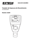
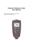
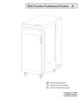
USER GUIDE Coating Thickness Tester With Bluetooth® Model CG304 Introduction Congratulations on your purchase of the Extech CG304 Coating Thickness Tester. The CG304 is a portable meter designed for non‐invasive coating thickness measurements with automatic recognition of the material under test. The meter uses two measurement methods: magnetic induction (for ferrous metal substrates) and eddy current (for non‐ferrous metal substrates). The Bluetooth® feature wirelessly transmits measurement data to a PC for further analysis and to generate report documentation. Proper use and care of this meter will provide many years of reliable service. Description Meter Description 1. LCD display 2. Power key 1 3. Probe 4. ARROW buttons Note: Battery compartment on rear of meter 2 Display Icon Description 4 NFe Non‐ferrous metals Fe Ferrous metals AUTO Automatic substrate recognition F or N Calibration icons DIR DIRECT mode 3 GRO1…4 GROUP Mode number µm Micrometers unit of measure mils mils = millimeters * 2.54/100 mm Millimeters unit of measure AVG Average reading MIN Minimum reading MAX Maximum reading SDEV Standard Deviation reading NO Number of data points Low battery Note: The unit of measure icon flashes when in the CONTINUOUS mode of operation. The unit of measure icon is stable when in the SINGLE mode of operation. 2 CG304-en-EU v1.1 7/14 Quick Start Instructions Meter Power Press the power button to switch the meter ON. The display will switch ON. If the display does not switch ON, install or replace the batteries. Measurements Use the film references and zero reference metal substrates to learn how the meter operates before moving to a professional application. The round metal substrate is the ferrous (magnetic) substrate and the rectangular shaped metal substrate is the non‐ferrous (non‐magnetic) substrate. The meter automatically senses ferrous and non‐ferrous substrates. 1. Place a reference film (250µm, for example) on the round, ferrous substrate. 2. Place the spring‐loaded meter sensor against the reference film. 3. In the single mode the meter will emit an audible tone indicating that the measurement has been taken. 4. In the continuous mode the display will continually measure and update the display 5. The LCD will show the reading (250µm) at the center of the display area. 6. A typical display will also show the following: NO = 1 (reading number one) on the lower left of the LCD AVG = 250µm (running average) on the lower right DIR = DIR mode of operation on the upper left Fe = Ferrous substrate on the upper right of the LCD DIR NO=1 250 Fe um AVG=250 Experiment with the remaining reference films and the substrate before using the meter professionally. Automatic Power OFF In order to conserve battery life, the meter will automatically turn off after approximately 10 minutes. To defeat this feature use the programming menu detailed in the next section (menu parameter AUTO POWER OFF under OPTIONS). 3 CG304-en-EU v1.1 7/14 Programming Menu The meter can be configured and calibrated through simple button presses in the programming menu. Press the LEFT button to access the menu and refer to the menu ‘tree’ below. The menu uses UP/DOWN, LEFT/RIGHT presses for navigation and selection. In the table below the factory default settings are in bold with an asterisk. Each parameter is explained in detail in the subsequent sections. Top level STATISTICAL VIEW Sub level 1 Sub level 2 Notes AVG* Average of a series of readings MIN Lowest of a series of readings MAX Highest of a series of readings NO Number of sampled readings SDEV Standard deviation of a series Single* One reading at a time Continuous Continuous measurements Measure mode Working mode Probe used OPTIONS Unit settings Backlight LCD Statistics Auto Power OFF LIMIT DELETE Limit settings Direct* Readings are not stored in groups Group 1…4 Store readings in groups Auto* Meter automatically selects mode Fe Ferrous measurement mode No Fe Non‐ferrous measurement mode µm* Micrometers mils Mils = mm * 2.54 / 100 mm Millimeters ON* Enables backlight operation OFF Disables backlight operation AVG* Average of a series of readings MAX Highest of a series of readings MIN Lowest of a series of readings SDEV Standard deviation of a series Enable* Allows auto power off to operate Disable Defeats the auto power off feature High Limit High Alarm alerts user when reached Low Limit Low Alarm alerts user when reached Delete Limits Clear the alarm limit values Current Data Delete current data All Data Delete all stored data Group Data Delete data stored data plus alarm and calibration data View stored data in all groups Enable Allow calibration access Disable Lock out the calibration mode Delete Zero N Clear the zero cal. data (non‐ferrous) Delete Zero F Clear the zero cal. data (ferrous) MEASUREMENT VIEW CALIBRATION NOTE: Disable the Auto Power OFF feature before lengthy programming to avoid inconvenient automatic power down while programming. 4 CG304-en-EU v1.1 7/14 STATISTICAL VIEWS Menu 1. Press the LEFT button to access the programming menu 2. Press the LEFT button to choose STATISTCAL VIEW 3. Use the UP and DOWN buttons to scroll through the AVERAGE, MINIMUM, MAXIMUM, NUMBER OF DATA, and SDEV (Standard Deviation) values for the stored readings. 4. ‘NO DATA’ will display if no readings are available for the meter to analyze. Stored readings will clear when the meter powers down unless the GROUP feature is used (refer to GROUP function explanation later in this section). 5. Press the BACK and then the ESC soft‐keys to return to the normal operating mode. OPTIONS Menu 1. Press the LEFT button to access the programming menu 2. Use the UP/DOWN button to scroll down to OPTIONS 3. Press LEFT button to select OPTIONS 4. Use the UP and DOWN buttons to scroll to the MEASURE MODE, WORKING MODE, PROBE USED, UNIT SETTINGS, BACKLIGHT, LCD STATISTICS, AND AUTO POWER OFF parameters. Use the LEFT soft‐key to select the desired parameter. Each parameter is detailed below: a. Measure Modes Select CONTINUOUS or SINGLE under MEASURE MODES in the OPTIONS Menu using the arrow buttons. In the CONTINUOUS measurement mode the meter displays a running average of readings as they are taken. Note that the audible measurement ‘beep’ is not active in this mode. In the SINGLE measurement mode measurements are taken one at a time. Single mode measurement readings are accompanied by an audible tone. b. Working Modes Select DIRECT or GROUP 1, 2, 3, or 4 under WORKING MODES in the OPTIONS Menu using the arrow buttons. In DIRECT mode, individual readings are logged to memory. When power is switched off or if the meter is switched to GROUP mode, all DIRECT readings will be cleared. However, the statistical analysis data will remain. The statistical analysis utility can evaluate up to 80 readings. When the memory is filled, new readings will replace old readings. Lastly, this mode has its own calibration and alarm limit values. In GROUP mode each group memory can store a maximum of 80 readings and 5 statistical values. Calibration and alarm limit values can be individually set and stored for each group. When the memory is filled, measurements will continue to be taken but readings will no longer log (previously logged readings are not affected); in addition, statistical data will no longer update. If desired, the group data, statistical values, calibration data, and alarm limit values can be deleted using the programming menu. 5 CG304-en-EU v1.1 7/14 c. Probe Used Select AUTO, Fe, or No Fe under PROBE USED in the OPTIONS Menu using the arrow buttons. In the AUTO mode, the meter automatically activates the probe measurement method (ferrous or non‐ferrous) based on the metal substrate that is being measured. When the probe is placed on a magnetic substrate it will work in the magnetic induction mode. If the probe is placed on a non‐ferrous metal it will work in the eddy current mode. In the Ferrous (Fe) Mode the Magnetic induction measurement mode is activated. In the Non‐Ferrous (No Fe) Mode the eddy current measurement mode is activated. d. Units of measure selections Select mm, µm or mils under UNIT SETTING in the OPTIONS Menu using the arrow buttons (mm = millimeters; µm = micrometers; mils = mm*2.54/100) e. Backlight Select ON or OFF under BACKLIGHT in the OPTIONS Menu using the arrow buttons. If OFF is selected the LCD backlighting will be completely disabled. If ON is selected, the user can adjust the brightness of the backlight. f. LCD Statistics Select AVERAGE, MINIMUM, MAXIMUM, or SDEV (Standard Deviation) under LCD STATISTICS in the OPTIONS Menu using the arrow buttons and the SELECT soft‐key. This selection determines which statistic is shown as default on the LCD display. g. Auto Power OFF Select ENABLE or DISABLE under AUTO POWER OFF in the OPTIONS Menu using the arrow buttons. When enabled, the meter automatically switches OFF after 10 minutes of inactivity. When disabled, the meter will only switch OFF with a button press or when the battery power is weak. h. Bluetooth ON/OFF Select ON or OFF under Bluetooth in the OPTIONS Menu using the arrow buttons. If OFF is selected the Bluetooth will be completely disabled. When Bluetooth is ON data will be automatically sent to PC, phone, or other Bluetooth receiving device. When the first connection is being made the device may prompt for a PIN number. In this case enter code 0000. Note: Turn on Bluetooth only when necessary as the battery will drain more quickly with Bluetooth powered ON. i. Gray scale contrast Press LEFT button to enter menu mode. Use arrow buttons to adjust the gray scale to desired contrast. 6 CG304-en-EU v1.1 7/14 DELETE Menu The DELETE menus allows for deleting current data, all data, and group data. The following parameters are available in the DELETE Menu: Delete Current data: Deletes current reading and updates the statistics (AVG, MIN, MAX, etc.) Delete All data: Delete all reading and statistical data. Delete Group data: This function duplicates the “Delete all data” function with additional, deletions of High alarm, Low alarm, and one‐ and two‐point calibrations. 1. Press the LEFT button to access the programming menu. 2. User the DOWN ARROW button to scroll down to DELETE. 3. Press LEFT to open the DELETE function. 4. User the ARROW keys to scroll to CURRENT, ALL, or GROUP. 5. Press LEFT again to choose CURRENT, ALL, or GROUP. MEASUREMENT VIEW Menu The Measurement View menu allows for scrolling through the readings in all of the groups. 1. Press the LEFT button to access the programming menu. 2. User the DOWN ARROW button to scroll down to MEASUREMENT VIEW. 3. Press LEFT to open the MEASUREMENT VIEW parameter. 4. User the ARROW buttons to scroll through the stored readings. CALIBRATION Menu The Calibration menu allows the user to enable/disable the calibration utility. The Calibration menu also allows the user to delete Zero calibration data for both ferrous (Zero F) and non‐ ferrous (Zero N) modes. 1. Press the LEFT button to access the programming menu. 2. Use the DOWN button to scroll down to CALIBRATION. 3. Press LEFT to open the CALIBRATION parameter. 4. Press UP/DOWN to delete zero point of Fe or Non‐Fe. 5. Press LEFT button for OK 6. Press RIGHT button to return. Measurement Considerations 1. After calibration, measurements should meet the published accuracy specifications. 2. Strong magnetic fields can affect the readings. 3. When using the statistical analysis functions for obtaining a mean value, take several readings of the same measurement area. False readings or outliers can then be removed (deleted) using the programming menu. 4. The final reading is derived from a statistical calculation with regard to the meter’s published accuracy specifications. 7 CG304-en-EU v1.1 7/14 Calibration Calibration Types The meter is factory calibrated before shipment to the customer; however the customer should perform a zero calibration and a multi‐point calibration before any critical measurements are taken. The calibration options are listed below. Read the description for each and select the best match for a given application. 1. Zero Point Calibration: Perform before each measurement session. 2. One Point Calibration: Use for high accuracy with repeated tests on a constant coating thickness. 3. Multi‐Point Calibration: Use for high accuracy within a known range of coating thickness. 4. Calibration for shot‐blasted surfaces. Calibration Considerations The calibration sample must correspond to the product sample in the following ways: Curvature radius Substrate material properties Substrate thickness Size of measurement area The point at which the calibration is made on the calibration sample must always be identical with the point of measurement on the product itself, especially in the case of corners and edges of small parts. To achieve the highest measurement accuracy, perform several calibrations in succession (for zero values and calibration film values). Preparing for calibration 1. Clean the probe tip (grease, oil, metal scrap, and the slightest impurity will affect measurement and distort readings). 2. Switch the meter ON (at a 4” [10cm] minimum distance from any metal). 3. Ready the supplied metal substrate samples and necessary films (supplied calibration reference films). 4. The meter is now ready for calibration. 8 CG304-en-EU v1.1 7/14 Zero calibration 1. Place the meter on an uncoated section of the material to be measured or on the reference substrate provided. Use either the Ferrous or Non‐Ferrous reference as required by the measurement application. a. Place the probe on the uncoated substrate and watch the LCD readings. b. When the readings appear stable, lift the meter off the substrate c. Press the LEFT button to enter menu d. Press UP/DOWN button to select zero‐point calibration. e. Press LEFT to enter or RIGHT to return to measurement mode. f. Press LEFT button to confirm calibration. 2. Press and hold the DOWN button to enter zero‐point calibration of Fe in measuring mode. 3. Press and hold UP button to enter zero‐point calibration of Non‐Fe measuring mode. Delete Fe or Non‐Fe zero‐point 1. Press LEFT button to enter menu 2. Press UP/DOWN button to select calibration 3. Press LEFT button to enter calibration 4. Press UP/DOWN to delete zero‐point of Fe or Non‐Fe 5. Press LEFT to select OK 6. Press RIGHT to return to normal operating mode. 9 CG304-en-EU v1.1 7/14 Statistical Analysis Considerations The meter calculates statistics from a maximum of 80 readings (For Group 1 through Group 4, a maximum of 400 readings can be stored). Note that readings cannot be stored when in DIRECT mode. However, statistics on these readings can still be calculated. When the meter is powered off or if the working mode is changed (in the programming menu), the DIRECT mode statistics will be lost. The following statistical values can be calculated: NO.: Number of readings AVG: Average value Sdev. : Standard deviation (square root of a data set’s variance) MAX: Maximum reading MIN: Minimum reading Statistical Terms x ) is the sum of readings divided by the number of readings. x x/n Average value ( Standard Deviation (Sdev) The sample standard deviation is a statistic that measures how the sample value is distributed around the sample mean. The standard deviation of a set of numbers is the root 2 mean square of the variance S The variance of a list is the square of the standard deviation of the list, that is, the average of the squares of the deviations of the numbers in the list from their mean divided by the(number of readings ‐1 ) Variance: S2= 2 ( x x ) /( n 1 ) 2 Standard deviation: S= S NOTE: Use the DELETE parameter from the programming menu immediately after an outlier or erratic reading has been taken. Refer to the Delete function in Programming Menu. Storage Capacity Overflow In GROUP mode, if the storage capacity is exceeded, statistics will not be updated, although measurements can still be made. If the memory is full, subsequent readings will not be included in the statistics. The meter’s display will show “FULL” (in the SINGLE measurement mode). In DIRECT mode, when the memory is full, the newest reading will replace the oldest reading and the statistics will be updated. 10 CG304-en-EU v1.1 7/14 Bluetooth® This meter has the capability to connect to and communicate with a PC via Bluetooth. To transfer data, enter the OPTIONS Menu and switch on Bluetooth as explained below. Measurement data will be sent automatically by way of the Bluetooth utility. Select ON or OFF under Bluetooth in the OPTIONS Menu using the arrow buttons. If OFF is selected the Bluetooth will be completely disabled. When Bluetooth is ON data will be automatically sent to PC, phone, or other Bluetooth receiving device. When the first connection is made the device may prompt for a PIN number. In this case enter code 0000. Note: Use Bluetooth only when necessary as the battery will drain more quickly with Bluetooth powered ON. Check the software download page of the website www.extech.com for the latest version of the PC software and its operating system compatibility. FCC COMPLIANCE This device complies with part 15 of the FCC Rules. Operation is subject to the following two conditions: 1. This device may not cause harmful interference. 2. This device must accept any interference received, including interference that may cause undesired operation. This equipment has been tested and found to comply with the limits for a Class B digital device, pursuant to part 15 of the FCC Rules. These limits are designed to provide reasonable protection against harmful interference in a residential installation. This equipment generates, uses, and can radiate radio frequency energy harmful interference to radio communications. However, there is no guarantee that interference will not occur in a particular installation. If this equipment does cause harmful interference to radio or television reception, which can be determined by turning the equipment off and on, the user is encouraged to try to correct the interference by one or more of the following measures: • Reorient or relocate the receiving antenna. • Increase the separation between the equipment and receiver. • Connect the equipment into an outlet on a circuit different from that to which the receiver is connected. • Consult the dealer or an experienced radio/TV technician for help. CAUTION: FCC Radiation Exposure Statement 1. This transmitter must not be co‐located or operating in conjunction with any other antenna or transmitter. 2. This equipment complies with FCC RF radiation exposure limits set forth for an uncontrolled environment. 3. To maintain compliance with FCC RF exposure compliance requirements avoid direct contact to the transmitting antenna during transmission. WARNING: Changes or modifications not expressly approved by the party responsible for compliance could void the user's authority to operate the equipment. 11 CG304-en-EU v1.1 7/14 INDUSTRY CANADA (IC) COMPLIANCE This device complies with Industry Canada license‐exempt RSS standard(s). Operation is subject to the following two conditions: (1) this device may not cause interference, and (2) this device must accept any interference, including interference that may cause undesired operation of the device. CAUTION: IC Radiation Exposure Statement 1. This transmitter must not be co‐located or operating in conjunction with any other antenna or transmitter. 2. This equipment complies with RSS 102 RF radiation exposure limits set forth for an uncontrolled environment. 3. To maintain compliance with RSS 102 RF exposure compliance requirements avoid direct contact to the transmitting antenna during transmission. Error Messages The following error messages will appear on the meter’s LCD if a problem arises. Err1: Eddy current probe error Err2: Magnetic induction probe error Err3: Eddy current and Magnetic induction errors Err4, 5, 6: Unused error displays Err7: Thickness error Please contact Extech Instruments if a problem exists. 12 CG304-en-EU v1.1 7/14 Maintenance Cleaning and Storage Periodically wipe the meter housing with a damp cloth and mild detergent; do not use abrasives or solvents. If the meter is not to be used for 60 days or more, remove the batteries and store them separately. Battery Replacement/Installation instructions 1. Remove the Phillips head screw that secures the rear battery door 2. Open the battery compartment 3. Replace/install the two 1.5V ‘AAA’ batteries 4. Secure the battery compartment Never dispose of used batteries or rechargeable batteries in household waste. As consumers, users are legally required to take used batteries to appropriate collection sites, the retail store where the batteries were purchased, or wherever batteries are sold. Disposal: Do not dispose of this instrument in household waste. The user is obligated to take end‐ of‐life devices to a designated collection point for the disposal of electrical and electronic equipment. 13 CG304-en-EU v1.1 7/14 Specifications Sensor probe Ferrous Non‐Ferrous Measurement principle Magnetic induction Eddy current principle Measuring range 0~2000μm 0~2000μm 0~78.7mils 0~78.7mils Accuracy 0~1000μm: ±(2% + 2μm) 0~1000μm: ±(2% + 2μm) (% of reading) 1000μm ~2000μm: (±3.5%) 1000μm ~2000μm: (±3.5%) 0~39.3mils: ±(2% + 0.08mils) 0~39.3mils: ±(2% + 0.08mils) 39.3mils ~78.7mils: (±3.5%) 39.3mils ~78.7mils: (±3.5%) 0~100μm: (0.1μm) 0~100μm: (0.1μm) 100μm ~1000μm: (1μm) 100μm ~1000μm: (1μm) 1000μm ~2000μm: (0.01μm) 1000μm ~1000μm: (0.01μm) 0~10mils: (0.01mils) 0~10mils: (0.01mils) 10mils~78.7mil:s (0.1mils) 10mils~78.7mils: (0.1mils) 1 Resolution Min. curvature radius 59.06mils (1.5mm) 118.1mils (3mm) Diameter of Min. area 275.6mils (7mm) 196.9mils (5mm) Basic critical thickness 19.69mils (0.5mm) 11.81mils (0.3mm) Industrial standards Conforms to GB/T 4956‐1985, GB/T 4957‐1985, JB/T 8393‐1996, JJG 889‐95, and JJG 818‐93 Operating Temperature 0°C~40°C (32°F~104°F) Operating Relative Humidity (R.H.) 20%~90% Relative Humidity Dimensions 120 x 62 x 32 mm (4.7 x 2.4 x 1.25”) Weight 175g (6.17 oz.) 1 Accuracy note: Accuracy statement applies to use on a flat surface, with a zero and a calibration performed near the thickness of the film to be measured, with an identical base metal and with the meter stabilized at ambient temperature. The accuracy of the reference films or any reference standards should be added to measurement results. Copyright © 2014 FLIR Systems, Inc. All rights reserved including the right of reproduction in whole or in part in any form www.extech.com 14 CG304-en-EU v1.1 7/14