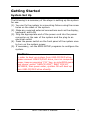
1
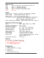
Acknowledgments
®
®
Intel Core i are registered trademarks of Intel Corporation.
IBM, PC/AT, PS/2 are trademarks of International Business
Machines Corporation.
®
®
Microsoft Windows is a registered trademark of Microsoft
Corporation.
RTL is a trademark of Realtek Semi-Conductor Co., Ltd.
Award is a registered trademark of Award Software
International, Inc.
All other product names or trademarks are properties of
their respective owners.
ii
WPE-796 User’s Manual
Safety Instructions
Thank you for purchasing the WPE-796 unit. We wish that this
unit will be durable and reliable in providing your digital signage
application needs. Please follow the instructions below to ensure
the unit continues to have high performance.
1. Please read this manual carefully and remember to keep this
manual for future reference.
2. Please disconnect this equipment from power outlet before
cleaning. Don‘t use liquid or sprayed detergent for cleaning.
3. If the unit does fall to the ground, immediately turn the power
off and disconnect cords. Then contact a service technician for
repairs. Continual use of the unit may result cause a fire or
electric shock. Also, do not repair the unit on your own.
4. If you wish to mount the unit, remember to use only the
mounting hardware recommended by the manufacturer.
5. This unit must operate on a power source as shown on the
specification label. If you are not sure what type of power
supply used in the area, consult your dealer or local power
supplier.
6. The power cords must not be damaged. Applied pressure,
added heat, and tugging may damage the power cord.
7. If the equipment is not use for long time, disconnect the
equipment from mains to avoid being damaged by transient
over-voltage.
8. Do not overload the AC outlets or extension cords. Electrical
shocks or fires may occur from overloading.
9. Do not touch the power source during a thunderstorm.
10. Use your thumb and index finger, grip firmly on the power
cord to disconnect from the electrical socket. By pulling the
power cord, may result in damaging it.
11. Do not insert objects into the openings.
12. Do not place the unit in the presence of high moisture areas.
13. Remember to keep the unit away from the presence of dust.
WPE-796 User’s manual
iii
14. Do not cover or block the openings on the top and back sides
of the Engine Box unit. Inadequate ventilation may cause
overheating thus reducing the lifespan of the unit.
15. Unless proper ventilation is present, do not place unit in an
enclosed area; such as a built-in shelf. Keep a minimum
distance of 10 cm around vent hole.
16. If the unit is not functioning properly, observe the
performance level of the display closely to determine what
type of servicing is needed.
17. Do not attempt to repair the Engine Box unit on your own.
Disassembling the cover exposes users’ to high voltages and
other dangerous conditions. Notify and request a qualified
service technician for servicing the unit.
18. If any of the following situations occur turn the power source
off and unplug the unit. Then contact a qualified service
technician.
(a) A liquid was spilled on the unit or objects have fallen into
the unit.
(b) The unit is soaked with liquids.
(c) The unit is dropped or damaged.
(d) If smoke or strange odor is flowing out of the operating
unit.
(e) If the power cord or plug is damaged.
(f) When the functions of the unit are dysfunctional.
19. When replacement parts are needed for the Monitor display
unit, make sure service technicians use replacement parts
specified by the manufacturer, or those with the same
characteristics and performance as the original parts. If
unauthorized parts are used it may result in starting a fire,
electrical shock and/or other dangers.
Caution:
DO NOT LEAVE THIS EQUIPMENT IN AN UNCONTROLLED
ENVIRONMENT WHERE THE STORAGE TEMPERATURE IS BELOW
-20° C (-4° F) OR ABOVE 80° C (140° F). THIS MAY DAMAGE THE
EQUIPMENT.
iv
WPE-796 User’s Manual
Declaration of Conformity
CE
This Engine Box is herewith confirmed to comply with the
essential protection requirements of Council Directive 93/42/EEC
on the approximation of the laws of the Member States relationg
to Electromagnetic Compatibility. This product has passed the CE
test for environmental specifications. Test conditions for passing
included the equipment being operated within an industrial
enclosure. In order to protect the product from being damaged by
ESD (Electrostatic Discharge) and EMI leakage, we strongly
recommend the use of CE-compliant industrial enclosure
products.
FCC safety
This device complies with Part 15 FCC Rules. Operation is subject
to the following two conditions: (1) this device may not cause
harmful interference, and (2) this device must accept any
interference received including interference that may cause
undesired operation.
Warning:
Any changes or modifications made to the equipment which are
not expressly approved by the relevant standards authority could
void your authority to operate the equipment.
Caution:
It may cause danger of explosion if battery is incorrectly replaced.
Replace only with the same or equivalent type recommended by
the manufacturer. Dispose of used batteries according to the
manufacturer’s instructions.
※ Use a 3V @ 210 mA lithium battery (Model No. CR2032)
WPE-796 User’s manual
v
Version Change History
Date
Version
2011/11/29 1.0
vi
Description
First release
WPE-796 User’s Manual
Remark
Cosa H.
Table of Contents
Acknowledgments........................................................ ii Safety Instructions ..................................................... iii Declaration of Conformity..........................................v Introduction..........................................................2 Product Description ......................................................2 Package list .....................................................................3 Features............................................................................4 Specifications..................................................................5 Getting Started ....................................................9 System Set Up ...............................................................9 Dimension ......................................................................10 Mounting Installation.................................................11 BIOS setup information..................................15 Appendix ..............................................................29 A. Jumper settings and Connectors .....................29 B. Wake UP on LAN Function..................................40 C. VGA card dimension .............................................41 WPE-796 User’s manual
1
Introduction
Product Description
The WPE-796 is designed for the Intel® Intel Core i3/i5/i7 CPU. It
is based on the Intel’s Q57 Express chipset and it comes with two
dual-channel DDR3 memory slots and 8GB memory capacity for
faster system responsiveness and support of 64-bit computing.
The WPE-796 engine box is aimed for high performance PC in the
digital, communications and industrial sector.
2
WPE-796 User’s Manual
Package list
Before you begin installing your Digital Signage Engine Box,
please make sure that the following items have been shipped:
• The WPE-796 engine box
• One CD containing user manual, QIG, chipset drivers
• Rubber foot x 4
• AC Power cord x 1
• L type Wall Mounting bracket x 2
• M3L6 Screws x 4
• M4L6 Screws x 4
• Hollow Mesh cover x 1
• Flat Mesh cover x 1
• M2L5 screws x 4 (for mesh cover use)
WPE-796 User’s manual
3
Features
Intel Q57 + ICH9 chipset Platform
Intel Core i3/i5/i7 CPU support (95W. Max)
Powerful Digital Signage Engine Box, support 1920x1080
HDTV content & 3D application
Compact and low noise design
1U rack design
Noise level under 37dB at 25℃., 45dB at 40℃
One Giga LAN
One PCI-E x 16 Slot for expansion
One PCI-E x 4 Slot for expansion
One Mini PCIe Card extension slot for optional wireless LAN 11
a/b/g/n
Mounting solution: 19” Rack mount / Wall mount
Windows® Win 7 embedded compatible
Kensington lock hole
RoHS compliance
4
WPE-796 User’s Manual
Specifications
[
System
CPU
System bus
Chipset
Audio
LAN
Memory
I/O
Serial ATA
USB
Serial COM
Mini PCIe
WDT
Smart fan
Storage
HDD
Intel® Socket LGA 1156, Support Intel Core
i3/i5/i7
CPU listing:
CORE i7-860, 2.80G, 8M Cache, 95W (w/o
integrated graphic)
CORE i5-750, 2.66G, 8M Cache, 95W (w/o
integrated graphic)
CORE i5-660, 3.33G, 4M Cache, 73W
CORE i5-650, 3.2G, 4M Cache, 73W
CORE i3-540, 3.06G, 4M Cache, 73W
Pentium G6950, 2.8G, 3M cache, 73W
2.5GT/s
Intel® Q57 Express PCH
Realtek ALC268 HD Audio Codec
Marvell 88E8071 Giga LAN x 1
Two DDR3 1066/1333 DIMM sockets (dual
channels), supports max. 8 GB
Winbond W83267UHG
SATA II controller (3.0Gb/sec) Port x 1
5 USB 3.0 port (I/O side x 3, internal pin head x
2)
1 RS-232/422/485 at I/O side
One Mini PCI express slot for wireless module as
option
1~255 second/minutes, software
programmable
PWM mode
SATA II 2.5” HDD drive bay x 1
Expansion
PCIe mini card Single 52-pin card-edge type, x1
PCI-E x16
Compatible to the PCI Express* Base Specification
revision 2.0 x1
PCI-E x4
Compatible to the PCI Express* Base Specification
revision 2.0 x1
WPE-796 User’s manual
5
External I/O
USB
USB 2.0 external x 3 (internal pin head x 2)
LAN
RJ-45 x 1 (Gigabit Ethernet)
COM
DB-9 x 1 (RS-232/422/485)
Audio
Mic-in, Line-out 3.5 mm audio stack
Video
DVI-I x 1
Power
Power Input Direct AC connector, 90~264VAC, 50/60Hz
Power switch
Power switch at front side x 1
Reset switch
Reset switch at front side x 1
LED status indicator Power/HDD LED indicator at front side x 1
(Dual color LED), (LED colors: Power:
Green / Orange: HDD accessing)
Add on slots power limitation 60W (include PCIe x16 + PCIe x1)
Mechanical & Environmental
Color
SECC, black (Panton no. 8238)
Operating Temperature: 0˚C ~ 50˚C
Storage Temperature
-20˚C ~ 80˚C
Operating Humidity
10 ~ 90%, non-condensing
Storage Humidity
10 ~ 90%, non-condensing
Net Dimensions
430 x 300 x 44.5 mm
Gross Dimensions
550 x 460 x 180 mm
Net Weights
5.5 kg (w/o add-on cards)
Gross Weight
5.8 kg (w/o add-on cards)
Noise level
Under 38dB(normal speed) / 45~48
dB(full speed) at 25℃
Kensington lock hole
I/O side x 1
Options:
1. mini PCIe, 11 a/b/g/n dual band
2. 19” rack mount kit x 1 (Ear type)
3. ATI HD5450 graphic card
4. ATI V4800 graphic card
Accessories:
1. Power Cord x 1
2. Wall mount kit x 1 (L type)
3. CD title x 1
4. Foot rip x 4
5. Hollow Mesh cover x 1
6
WPE-796 User’s Manual
6. Flat Mesh cover x 1
7. Screws
Regulatory
FCC-B, CE (EMC/LVD), VCCI, UL/cUL, CCC
Shock/Vibration/Drop
Shock
Operating: 15g/0.53 oz, 11 ms, half sine wave
Non-operating: 50g/1.76 oz, 11 ms, half sine wave
Vibration
Operation:
5~22HZ: 0.25G
22~350HZ: 0.5G
350~500HZ: 0.25G
Non-operation
5~22HZ: 0.25G
22~350HZ: 2G
350~500HZ: 1G
CYCLE TIME: 1 MINUTE
DIRECTION: X,Y,Z (one direction TIME is 10 MINUTES)
Drop
Drop height: 91 cm
Packing cushion material: EPE
Drop sequence: 6 faces (Total of 6 drops)
WPE-796 User’s manual
7
8
WPE-796 User’s Manual
Getting Started
System Set Up
The following is a summary of the steps in setting up the system
for use.
(1). You can fix the system to a mounting fixture using the screw
holes on the sides of the system.
(2). Make any required external connections such as the display,
keyboard, and LAN.
(3). Plug the appropriate end of the power cord into the power
connector on the rear of the system and the plug to an
electrical outlet.
(4). Press the power switch on the front panel of the system once
to turn on the system power.
(5). If necessary, run the BIOS SETUP programs to configure the
system.
Caution:
In order to boot up system from USB-CD/DVD drive,
please connect USB-CD/DVD drive, turn on computer
power, keep on pressing “F11” key, go into BIOS quick
boot menu, select “USB-CD ROM”, WAIT FOR 20
SECONDS, then press enter, system OS will boot up
from USB-CD/DVD drive directly.
WPE-796 User’s manual
9
Dimension
10
WPE-796 User’s Manual
Mounting Installation
The WPE-796 provides several mounting solutions to help system
integrators conveniently integrate the Engine Box into their
system.
Never use any other mounting brackets except those provided by
manufacturer to prevent the unreliable fixing of WPE-796.
Mounting installation should be carried out by a professional
technician. Please contact the service technician or your retailer if
you need this service.
Caution:
Be sure to secure the screws of the mounting bracket tightly.
Injuries could result if the WPE-796 isn’t properly secured to
the mounting bracket.
Wall Mounting
Caution:
When WPE-796 is erected to mount on a monitor, the ambient
temp should not be over 45℃.
i) When I/O face right
Content:
L type bracket x 2
M3L6 Screws x 4 (screw on WPE-796)
M4L6 Screws x 4 (screw on mounting place)
(Wall mounting kit has been attached in accessory box of unit)
Step 1: Fix the L type bracket on WPE-796 unit with M3L6 screws.
Step 2: Use M4L6 four screws to screw the WPE-796 on mounting
place.
WPE-796 User’s manual
11
ii) When I/O face down
Content:
L type bracket x 2
M3L6 Screws x 4 (Screw on WPE-796)
M4L6 Screws x 4 (Screw on mounting place)
Hollow Mesh cover x 1
Flat Mesh cover x 1
M2L5 Screws x 4 (Screw on mesh covers)
Step 1: Fix the L type bracket on WPE-796 unit with M3L6 screws.
Step 2: Use M4L6 four screws to screw the WPE-796 on mounting
12
WPE-796 User’s Manual
place.
Step 3: Use M2L5 four screws to screw the mesh covers on
WPE-796 I/O bracket.
Rack Mounting (Option)
"Rack Mount Instructions - The following or similar rack-mount
instructions are included with the installation instructions:
A) Elevated Operating Ambient - If installed in a closed or
multi-unit rack assembly, the operating ambient temperature of
the rack environment may be greater than room ambient.
Therefore, consideration should be given to installing the
equipment in an environment compatible with the maximum
ambient temperature (Tma) specified by the manufacturer.
B) Reduced Air Flow - Installation of the equipment in a rack
should be such that the amount of air flow required for safe
operation of the equipment is not compromised.
WPE-796 User’s manual
13
C) Mechanical Loading - Mounting of the equipment in the rack
should be such that a hazardous condition is not achieved due to
uneven mechanical loading.
D) Circuit Overloading - Consideration should be given to the
connection of the equipment to the supply circuit and the effect
that overloading of the circuits might have on over current
protection and supply wiring. Appropriate consideration of
equipment nameplate ratings should be used when addressing
this concern.
E) Reliable Earthing - Reliable earthing of rack-mounted
equipment should be maintained. Particular attention should be
given to supply connections other than direct connections to the
branch circuit (e.g. use of power strips)."
Content:
Rack-L bracket x 1
Rack-R bracket x 1
M4L6 Screws x 4 (Screw on WPE-796)
M5L12 screws x 4 (Screw on rack)
Step 1: Use M4L6 four screws to screw the Rack-L bracket and
Rack-R bracket on WPE-796 two sides.
Step 2: Use M5L12 four screws to screw WPE-796 on Rack.
14
WPE-796 User’s Manual
BIOS setup information
BIOS Introduction
The AMI BIOS (Basic Input/Output System) installed in your
computer system’s ROM supports Intel processors. The BIOS
provides critical low-level support for a standard device such as
disk drives, serial ports. It also adds virus and password
protection as well as special support for detailed fine-tuning of
the chipset controlling the entire system.
BIOS Setup
The AMI BIOS provides a Setup utility program for specifying the
system configurations and settings. The BIOS ROM of the system
stores the Setup utility. When you turn on the computer, the
Award BIOS is immediately activated. Pressing the <Del> key
immediately allows you to enter the Setup utility. If you are a
little bit late pressing the <Del> key, POST (Power On Self Test)
will continue with its test routines, thus preventing you from
invoking the Setup. If you still wish to enter Setup, restart the
system by pressing the ”Reset” button or simultaneously
pressing the <Ctrl>, <Alt> and <Delete> keys. You can also
restart by turning the system Off and back On again. The
following message will appear on the screen:
Press <DEL> to Enter Setup
In general, you press the arrow keys to highlight items, <Enter>
to select, the <PgUp> and <PgDn> keys to change entries, <F1>
for help and <Esc> to quit.
When you enter the Setup utility, the Main Menu screen will
appear on the screen. The Main Menu allows you to select from
various setup functions and exit choices.
WPE-796 User’s manual
15
The section below the setup items of the Main Menu displays the
control keys for this menu. At the bottom of the Main Menu just
below the control keys section, there is another section, which
displays information on the currently highlighted item in the list.
Note:
If the system cannot boot after making and
saving system changes with Setup, the Award
BIOS supports an override to the CMOS
settings that resets your system to its default.
Warning: It is strongly recommended that you avoid
making any changes to the chipset defaults.
These defaults have been carefully chosen by
both Award and your system manufacturer to
provide the absolute maximum performance
and reliability. Changing the defaults could
cause the system to become unstable and
crash in some cases.
16
WPE-796 User’s Manual
Main
AMI BIOS Setup Utility
Standard Main
System Overiew
Item Help
Processor
Intel® Core™ i5 CPU
650 3.2GHz
Speed
3200MHz
Count
1
System Memory
Size
3896MB
System Time
[hh:mm:ss]
System Date
[mm/dd/yyyy]
At the bottom of the menu are the control keys for use on this
menu. If you need any help in each item field, you can press the
<F1> key. It will display the relevant information to help you. The
memory display at the lower right-hand side of the menu is
read-only. It will adjust automatically according to the memory
changed. The following describes each item of this menu.
System Time
Configure system Time
Date
Configure system Date
WPE-796 User’s manual
17
Advanced
AMI BIOS CMOS Setup Utility
Advanced
Advanced Setting
Item Help
WARNING: Setting wrong values in below
sections may cause system to malfunction.
CPU Configuration
IDE Configuration
SuperIO Configuration
Hardware Health Configuration
APM Configuration
ACPI Configuration
CPU Configuration
MPS and ACPI MADT ordering
MPS and ACPI MADT ordering. Modren ordering for Windows XP or
Later OSes. Legacy ordering for Windows 2000 or earlier OSes.
Intel(R) Virtualization Tech
When enabled, a VMM can utilize the additional HW Caps. Provided
by Intel(R) Virtualization Tech. Note: A full reset is required to
change the setting.
Active Processor Cores
Number of cores to enable in each processor package
A20M
Legacy OSes and APs may need A20M enabled.
Intel(R) Speed Step (TM) tech
Disable: Disable GV3
Enable: Enable GV3
Intel(R) Turbo Mode tech
Turbo mode allows processor cores to run faster than marked
frequency in specific condition.
Intel(R) C-STATE tech
CState: CPU idle is set to C2/C3/C4
C State package limit setting
Selected option will program into C State package limit register.
IDE Configuration
Configure SATA as
IDE, RAID, AHCI, Disabled
18
WPE-796 User’s Manual
SATA#1 IDE configuration
Compatible, Enhanced.
SATA#2 IDE configuration
Disabled, Enhanced.
Primary IDE Master
Type
Select the type of device connected to the system.
LBA/Large Mode
Disabled: Disables LBA Mode.
Auto: Enables :BA Mode if the device supports it and the device is
not already formatted with LBA Mode disabled.
Block (Multi-Sector Transfer)
Disabled: The Data transfer from and to the device occurs one
sector at a time.
Auto: The Data transfer from and to the device occurs multiple
sectors at a time if the device supports it.
PIO Mode
Select PIO Mode
DMA Mode
Select DMA Mode
Auto: Auto detected
SWDMAn: Single Word DMAn
MWDMAn: Multi Word DMAn
UDMAn: Ultra DMAn
S.M.A.R.T.
S.M.A.R.T. stands for Self-Monitoring, Analysis and Reporting
Analysis and Reporting Technology.
32Bit Data Transfer
Enable/Disable 32Bit Data Transfer
Primary IDE Slave
Type
Select the type of device connected to the system.
LBA/Large Mode
Disabled: Disables LBA Mode.
Auto: Enables :BA Mode if the device supports it and the device is
not already formatted with LBA Mode disabled.
Block (Multi-Sector Transfer)
Disabled: The Data transfer from and to the device occurs one
sector at a time.
Auto: The Data transfer from and to the device occurs multiple
sectors at a time if the device supports it.
PIO Mode
Select PIO Mode
DMA Mode
WPE-796 User’s manual
19
Select DMA Mode
Auto: Auto detected
SWDMAn: Single Word DMAn
MWDMAn: Multi Word DMAn
UDMAn: Ultra DMAn
S.M.A.R.T.
S.M.A.R.T. stands for Self-Monitoring, Analysis and Reporting
Analysis and Reporting Technology.
32Bit Data Transfer
Enable/Disable 32Bit Data Transfer
Secondary IDE Master
Type
Select the type of device connected to the system.
LBA/Large Mode
Disabled: Disables LBA Mode.
Auto: Enables :BA Mode if the device supports it and the device is
not already formatted with LBA Mode disabled.
Block (Multi-Sector Transfer)
Disabled: The Data transfer from and to the device occurs one
sector at a time.
Auto: The Data transfer from and to the device occurs multiple
sectors at a time if the device supports it.
PIO Mode
Select PIO Mode
DMA Mode
Select DMA Mode
Auto: Auto detected
SWDMAn: Single Word DMAn
MWDMAn: Multi Word DMAn
UDMAn: Ultra DMAn
S.M.A.R.T.
S.M.A.R.T. stands for Self-Monitoring, Analysis and Reporting
Analysis and Reporting Technology.
32Bit Data Transfer
Enable/Disable 32Bit Data Transfer
Secondary IDE Slave
Type
Select the type of device connected to the system.
LBA/Large Mode
Disabled: Disables LBA Mode.
Auto: Enables :BA Mode if the device supports it and the device is
not already formatted with LBA Mode disabled.
Block (Multi-Sector Transfer)
Disabled: The Data transfer from and to the device occurs one
sector at a time.
20
WPE-796 User’s Manual
Auto: The Data transfer from and to the device occurs multiple
sectors at a time if the device supports it.
PIO Mode
Select PIO Mode
DMA Mode
Select DMA Mode
Auto: Auto detected
SWDMAn: Single Word DMAn
MWDMAn: Multi Word DMAn
UDMAn: Ultra DMAn
S.M.A.R.T.
S.M.A.R.T. stands for Self-Monitoring, Analysis and Reporting
Analysis and Reporting Technology.
32Bit Data Transfer
Enable/Disable 32Bit Data Transfer
Hard Disk Write Protect
Disable/Enable device write protection. This will be effective only if
device is accessed through BIOS.
IDE Detect Time Out (Sec)
Select the out value for detecting ATA/ATAPI device(s).
Super IO Configuration
Serial Port1 Address
Allows BIOS to Select Serial Port1 Base Addresses.
Hardware Health Configuration
CPUFAN Mode Setting
Fan configuration mode setting
SYSFAN0 Mode Setting
Fan configuration mode setting
APM Configuration
Power Management/APM
Enable or disable APM.
Resume On RTC Alarm
Disable/Enable RTC to generate a wake event
ACPI Configuration
General ACPI Configuration
Suspend mode
Select the ACPI state used for System Suspend.
Repost Video on S3 Resume
Determines whether to invoke VGA BIOS post on S3/STR
WPE-796 User’s manual
21
Advanced ACPI Configuration
ACPI Version Features
Enable RSDP pointers to 64-bit Fixed System Description Tables. Di ACPI
version has some.
ACPI APIC support
Include ACPI APIC table pointer to RSDT pointer list
AMI OEMB table
Include OEMB table pointer to R(X)SDT pointer list
Headless mode
Enable/ Disable Headless operation mode through ACPI
Chipset ACPI Configuration
APIC ACPI SCI IRQ
Enable/Disable APIC ACPI SCI IRQ
High Performance Event Timer
Enable/Disable APIC ACPI SCI IRQ
22
WPE-796 User’s Manual
Boot
AMI BIOS CMOS Setup Utility
Boot
Boot Setting
ITEM HELP
Boot Settings Configuration
Boot Device Priority
Hard Disk Drives
Boot Settings Configuration
Quick Boot
Allows BIOS to skip certain tests while booting. This will
decrease the time needed to boot the system.
Quiet Boot
Disabled: Displays normal POST messages
Enable: Displays OEM Logo instead of POST messages.
Add On ROM Display Mode
Set display mode for Option ROM
Boot up Num-Lock
Select Power-on state for Numlock.
PS/2 Mouse Support
Select sipport for PS/2 Mouse
Wait For “F1” If Error
Wait for F1 key to be pressed if error occurs
Hit “DEL” Message Display
Displays “Press Del to run Setup” in POST
Interrupt 19 Capture
Enabled: Allows option ROMs to trap interrupt 19
Boot Device Priority
1st Boot Device
Specifies the boot sequence from the available devices.
A device enclosed in parenthesis has been disabled in the
corresponding type menu.
2nd Boot Device
Specifies the boot sequence from the available devices.
A device enclosed in parenthesis has been disabled in the
corresponding type menu.
WPE-796 User’s manual
23
Hard Disk Drives
1st Drive
Specifies the boot sequence from the available devices.
24
WPE-796 User’s Manual
Security Setting
AMI BIOS CMOS Setup Utility
Security Setting
Security Setting
ITEM HELP
Change Supervisor Password
Change User Password
Boot Sector Virus Protection
Change Supervisor Password
Install or Change the password.
Change User Password
Install or Change the password.
Boot Sector Virus Protection
Enable/Disable Boot Sector Virus Protection.
WPE-796 User’s manual
25
Power Management Setup
Phoenix - AwardBIOS CMOS Setup Utility
Power Management Setup
Advanced Chipset Settings
ITEM HELP
North Bridge Configuration
South Bridge Configuration
North Bridge Configuration
Memory Remap Feature
ENABLE: Allow remapping of overlapped PCI memory above
the total physical memory.
DISABLE: Do not allow remapping of memory.
DRAM Frequency
Auto, 800, 1067, 1333, 1600
Configure DRAM Timing by SPD
Auto, Manual
Memory Hole
Disabled, 15MB-16MB
DRAM Margin Ranks
Disabled, Enabled
Hybrid Multi-Monitor
Allowing for operability of IGD and PEG independently-driven
displays
Initiate Graphic Adapter
Select which Graphics controller to use as the primary boot
device.
IGD Graphics Mode Select
Select the amount of system memory used by the Internal
graphics device.
PEG Port
Auto, Disabled
Video Function Configuration
DVMT Mode Select
DVNT/FIXED Memory
South Bridge Configuration
USB Function
26
WPE-796 User’s Manual
Enable/Disable USB controller in system.
EHCI Controller#1
Enable Intergraded USB 2.0 RMH#1
EHCI Controller#2
Enable Intergraded USB 2.0 RMH#2
HAD Controller
Enabled, Disabled
Restore on AC Power Loss
Power Off, Power On, Last State
WPE-796 User’s manual
27
Exit Option
AMI BIOS CMOS Setup Utility
Exit Option
Exit Option
ITEM HELP
Save Changes and Exit
Discard Changes and Exit
Discard Changes
Load Optimal Defaults
Load Failsafe Defaults
Save Changes and Exit
Exit system setup after saving the changes.
Discard Changes and Exit
Exit system setup without saving any changes.
Discard Changes
Discards changes done so far to any of the setup questions.
Load Optimal Defaults
Load Optimal Default values for all the setup questions.
Load Failsafe Defaults
Load Failsafe Default values for all the setup questions..
28
WPE-796 User’s Manual
APPENDIX
Appendix
A. Jumper settings and Connectors
Note: Some of jumpers or connectors will be removed
base on system configuration.
J
J J6
7
DVI1
J
2
J
8
h
C
(
2
M
M
I
D
4
1
J
PJ
CPU
Socket
LGA1156
J
J
) )
B
A
l e
l
n
n
a
h
C
(
1
M
M
I
D
3
1
J
J
J
B
P
Intel
Q57
J
J
1
2
I
V
D
J
2
J1
J J J
3 4 5
J
J
J
B J
J29 J31
WPE-796 User’s manual
J
J
29
APPENDIX
30
WPE-796 User’s Manual
APPENDIX
WPE-796 User’s manual
31
APPENDIX
32
WPE-796 User’s Manual
APPENDIX
WPE-796 User’s manual
33
APPENDIX
34
WPE-796 User’s Manual
APPENDIX
WPE-796 User’s manual
35
APPENDIX
36
WPE-796 User’s Manual
APPENDIX
WPE-796 User’s manual
37
APPENDIX
38
WPE-796 User’s Manual
APPENDIX
WPE-796 User’s manual
39
APPENDIX
B. Wake UP on LAN Function
Please make sure the AC power is ON before use the
function.
1. Boot into OS (windows XP).
2. In start menu control panel System device manager Network
adapters double click Marvell Yukon 88E8071 Advance Wake
from Shutdown Item select Wake on Magic packet from power off
state.
Please shutdown system and wait for wake on LAN after finish
these procedures.
40
WPE-796 User’s Manual
APPENDIX
C. VGA card dimension
Notice:
Add on slots power limitation: 60W (include PCIe x16 + PCIe x1)
i) When both of graphic card(PCIe x16) and TV tuner
card(PCIe x1) insert in WPE-796.
WPE-796 User’s manual
41
APPENDIX
ii) When insert graphic card only.
42
WPE-796 User’s Manual