1
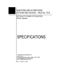
TOPO
OPERATION MANUAL
Machine Control, Inc.
TOPO MANUAL
WELCOME TO TOPO
Topo easily and rapidly captures the data points that define a field’s surface. These
points can be loaded into other programs to generate contour lines, compute
volumes, design landforms and water management systems, and much more.
Whether using the touchscreen interface or utilizing a standard keyboard, Topo can
be navigated easily during a site survey. The software can be adapted to nearly any
vehicle or even used by a surveyor on foot.
Topo can be set to work in international and U.S. Survey feet or meters. A typical
user in the USA will choose U.S. Survey feet. All numbers will be calculated and
displayed in tenths of feet, so that 6.5' is the same as 6'6".
© AMW Machine Control, Inc. All rights reserved.
2
TOPO MANUAL
CONTENTS
Definition of Terms ........................ . . 4
Pass Labels . . . . . . . . . . . . . . . . . . . . . . . . . . . . . . . . . .. 18
File Types ..................................... . . 5
Grids .. . . . . . . . . . . . . . . . . . . . . . . . . . . . . . . . . . . . . . . ... 19
Job Setup . . ................................... . . . 6
Pass Types .. . . . . . . . . . . . . . . . . . . . . . . . . . . . . . . . ... 21
Configuring GPS ........................... . . . 9
Topo a Field . . . . . . . . . . . . . . . . . . . . . . . . . . . . . . . . .. 22
Control Points .............................. . 11
Reference Points .. . . . . . . . . . . . . . . . . . . . . . . ... 23
Working Screen ............................ . 12
Export Data .. . . . . . . . . . . . . . . . . . . . . . . . . . . . . . ... 24
Touch Keyboard/Keypad ................ . 14
Quit the Application . . . . . . . . . . . . . . . . . . . . ... 25
Buttons Menu ............................... 15
Troubleshoot Topo . . . . . . . . . . . . . . . . . . . . . ... 26
Click Menu . . .................................. 16
© AMW Machine Control, Inc. All rights reserved.
3
TOPO MANUAL
DEFINITION OF TERMS
Capture
Collecting data points.
Control Point
A point of known elevation, usually tied to world coordinates. A benchmark.
Device
Interface device that automatically controls the blade, such as a control module.
Instrument Positional equipment, typically GPS.
Local Point NEZ coordinate system that uses ‘fake’ coordinates, meaning they are not consistent with State Plane or UTM.
Machine Control
Automatic control of the blade.
NEZ
Coordinate system of feet and meters, rather than latitude, longitude and altitude. Northing (N) Easting (E) Elevation (Z).
Plot Graphic display window on the Working Screen.
State Plane NEZ coordinate system with zones designed for each state.
Survey File (.svy)
File that contains all the data points captured, and other relevant information.
Rod Distance from the GPS antenna reading point to the blade or ground.
UTM NEZ coordinate system with zones designed on longitudinal lines.
© AMW Machine Control, Inc. All rights reserved.
4
TOPO MANUAL
FILE TYPES
Most files used by Topo will be stored in the directory named C:\AMW\DATA.
Control Points File
The Control Points File (.CTL) is used while setting up an instrument. The .CTL
extension automatically attaches to the job name. It can also be copied from
another file. This file uses the NEZ description (Northing-Easting-Elevation.) Points
from this file will be displayed on your plot window as small triangles. The control
point stored in the .CTL file are known world coordinates, sometimes called
benchmarks. They allow the data sets to match up to those collected and used
earlier in a job.
Survey File
A Survey File (.SVY) contains the points captured when collecting topographic
data on a surface. This file starts out empty when you create a new job, and the
.SVY file extension automatically attaches to the job name. Points from this file
will be displayed on your plot window as dots. This file is usually used to generate
an NEZ (Northing-Easting-Elevation) file and/or a Drawing Exchange File (.DXF) to
import into other programs.
Drawing File
A Drawing File (.DRW) defines the background image to be displayed on the plot
window, along with the other data. A .DRW file is generally built from a .DXF file.
Ground Surface File
A surface file (.FBG) built from a design file. This file can be created from many
other file types. An .FBG file is almost always used for pre-designed jobs.
© AMW Machine Control, Inc. All rights reserved.
5
TOPO MANUAL
JOB SETUP
See Dashboard Operation Manual for more detail.
A
B
C
D
A. Select Topo.
B. Select an existing job or set up a new job.
C. Verify the setup type, region, antenna or rod height, GPS instrument,
and GPS quality.
D. Press Start to open the Working Screen.
© AMW Machine Control, Inc. All rights reserved.
6
TOPO MANUAL
JOB SETUP
When setting up a new job, there are several coordinate system options. Typically,
a new job will use a 0 Point option as there will not be pre-existing control points.
Use Previous Setup
Use this option when returning to a prior job and using a “smart” base station or
the Continuously Operating Reference Stations (CORS) Network.
UTM Coordinates, 0 Point
Create a job with no preset control points. Topo will determine the correct zone
using the worldwide coordinate system, or it can be selected from a list.
UTM Coordinates, 1 Point
Select to enter a job with an existing UTM control point. Topo will determine the
correct zone using the worldwide coordinate system, or it can be selected from a
list.
2 Local Point Setup
Select to enter a job with two or more existing control points. The job orientation
is based on two control points, without relying on a coordinate system.
State Plane, 0 Point
Use this option when entering a job with no preset control points in the United
States. Select the appropriate State Plane zone from the 124 geographic areas
across the country.
State Plane, 1 Point
If you have preset control points, choose this option to work within the State
Plane Coordinate system. Select the appropriate zone for your location, select the
correct control points and read the instrument
TM Grid, 0 Point
Use this option in Australia when entering a job with no preset control points.
TM Grid, 1 Point
Use this option in Australia when entering a job with a control point.
© AMW Machine Control, Inc. All rights reserved.
7
TOPO MANUAL
JOB SETUP
The Universal Transverse Mercator zones are part of a worldwide coordinate
system that divides the earth into sections emanating from the poles, accounting
for the curvature of the earth.
The State Plane coordinate system identifies zones within each state, but does not
account for the curvature of the earth.
© AMW Machine Control, Inc. All rights reserved.
8
TOPO MANUAL
CONFIGURING GPS
The following tables list the output options that should be enabled on common
brands of GPS systems. If your GPS system does not appear on this list, please
contact your dealer or technician for setup details and assistance. The Hz
(update) rate and Baud rate must also be determined. To set these in Topo, press
the Menu icon, select Instrument Menu, Control the Instrument and adjust the Hz
and Baud rates.
BRAND
MESSAGE TYPE
HZ RATE
BAUD RATE
ASHTECH™
GGA
10
57600
TOPCON™
GGA
10
57600
JD™ ITC
GGA
5
38400
JD™ 3000
GGA
10
57600
NOVATEL™
BESTPRO
10
57600
300/410
BESTPRO
10
57600
TRIMBLE™ (OLDER)
GGK
10 & ASAP
38400
TRIMBLE™ (NEWER)
GGA
10
57600
Each individual RTK-GPS system will have a standard for being in fix, and the type
of data and degree of precision it returns.
BRAND
RTK FIXED
RTK FLOAT
NO RTK
BASE
PRECISION
GGA (GENERIC/ASHTECH™)
4 OR 3
5 OR 2
1
HDOP
JOHN DEERE™
4
10
57600
HDOP
NOVATEL™ /SOKKIA™ /BEELINE™
50
5
38400
ALT. STD. DEVIATION
TOPCON™ (JAVAD™ JGGA)
4
5
1
HDOP
TRIMBLE™ (GGK)
3
2
1
HDOP
© AMW Machine Control, Inc. All rights reserved.
9
TOPO MANUAL
CONFIGURING GPS
HDOP, VDOP and PDOP are abbreviations for the Horizontal, Vertical and
Positional (3D) dilution of precision. The precision of multiple satellites in view
of a receiver, combined with their relative positions, determines the level of
precision.
When visible GPS satellites are close together in the sky, the geometry is said
to be weak and the DOP value is high; when they are far apart, the geometry is
strong and the DOP value is low. Thus, a low DOP value represents a better GPS
positional precision due to the wider angular separation between the satellites
that were used to calculate a GPS unit’s position. Other factors that can increase
the effective DOP are obstructions, such as nearby mountains or buildings.
DOP VALUE
RATING
DESCRIPTION
<1
Ideal
This is the highest possible confidence level to be used for
applications demanding the highest possible precision at all times.
1-2
Excellent
At this confidence level, positional measurements are considered
accurate enough to meet all but the most sensitive applications.
2-3
Good
This level marks the minimum standard appropriate for making
business decisions. Positional measurements could be used for
reliable in-route navigation suggestions.
>3
Poor
This confidence level should be used only to indicate a very rough
estimate of a current location.
© AMW Machine Control, Inc. All rights reserved.
10
TOPO MANUAL
CONTROL POINTS
A control point, or benchmark, is a known location in the real world. It has
associated coordinate data, and can be accessed at a later date independent of
a base station or repeater system. They are required for exact repeatability from
topo collection to tiling, and are recommended for day-to-day operations.
Control points can be collected using the Dashboard or Quit Menu. From the Quit
Menu, select Capture a Control Point.
Select a Rod Length
Choose from the typical rod length,
or enter a custom measurement.
Read the Instrument
Pause before reading, and set the
‘Tries’ to 10 or 20 when capturing a
point in dense tree cover.
Name the Control Point
After receiving confirmation, name
the point and enter a description.
The default name is ‘1’ and will
increase for each following control
point. The point name must be
between one and eight letters and/
or numbers. The descriptions can
be any length.
© AMW Machine Control, Inc. All rights reserved.
11
TOPO MANUAL
WORKING SCREEN
See Working Screen and Menus manual for more detail.
H
L
A
B
M
I
C
D
E
K
F
G
J
A. Zoom In/Out
H. Menu Bar
B. View All
I. Plot Screen
C. Neighborhood View
J. Info Bar
D. Path Offset
K. Current Position
E. Turn On/Off Old Points
L. Capture Mode
F. Buttons Menu
M. Manual Point Capture
G. Grid Menu
© AMW Machine Control, Inc. All rights reserved.
12
TOPO MANUAL
WORKING SCREEN
See Working Screen and Menus manual for more detail.
E
A
F
B
G
C
H
D
A. Main Menu
E. Turn Capture Mode on/off
B. Enable Slope Indicator
F. 2PER label mode
C. Quit Menu/Return to Dashboard
G. 3GRD label mode
D. Guidance Light Bar
H. Capture a Control Point
© AMW Machine Control, Inc. All rights reserved.
13
TOPO MANUAL
TOUCH KEYBOARD/KEYPAD
You can navigate all aspects of Topo using either the touchscreen or keyboard.
Touch any text box, such as the job name or job description, to activate the onscreen keyboard.
An on-screen numeric keypad will appear where a number entry is needed.
© AMW Machine Control, Inc. All rights reserved.
14
TOPO MANUAL
BUTTONS MENU
The Buttons Menu utilizes keyboard hot keys for commonly used program
functions. Some functions are only available when Topo is installed with an AMW
machine control program, such as Pipe or Road.
HOT KEY
FUNCTION
HOT KEY
FUNCTION
BACKSPACE
Switch pass
P
Pass Menu
PAGE UP
Move blade up
Q
Quit Menu
PAGE DOWN
Move blade down
R
Specify radius to show
ARROW UP
Half of page up
S
Show view from the side
ARROW DOWN
Half of page down
T
Show view from the top
SPACE BAR
Toggle auto capture
U
Main Menu
LEFT MOUSE BUTTON Click Menu
V
Toggle side and top view
A
Show all points
W
Show view from the west
B
Buttons Menu
X
Grid Menu
C
Find closest control point
Z
Show 3D view looking NNE
D
Find closest data point
0
Toggle machine control on/
off
E
Show view from the east
1
Set rod length
F
Cut/fill offset (subgrade)
2
Set point label
G
Toggle stop/go mode
3
Specify a 3D view
I
Zoom in
4
Set the next point number
K
Mark special points
6
Control the instrument
L
Draw line between points
7
Capture a note
M
Manually capture a point
8
Display/Plot Menu
N
Show neighborhood of
current position
9
Devices Menu
O
Zoom out
=
Switch rod-length offset
© AMW Machine Control, Inc. All rights reserved.
15
TOPO MANUAL
CLICK MENU
Touch the plot window of the Working Screen to activate the Click Menu. This
menu allows the user to select which function will occur when the mouse buttons
are clicked. Each function is designed to assist in surveying.
© AMW Machine Control, Inc. All rights reserved.
16
TOPO MANUAL
CLICK MENU
The Click Menu contains the following options:
FUNCTION NAME
DESCRIPTION
SET NEZ AS ‘FAKE
POSITION’
Sets the currently displayed NEZ as a ‘fake’ position. This position will be used
for the zoom, grid and other functions instead of your actual position.
TURN OFF ANY ‘FAKE’
CURRENT POSITIONS
Turns off any ‘fake’ positions. After using the scroll icon to move around the
screen, you must turn off any ‘fake’ positions to re-center the screen on the
actual current position.
SNAP TO CLOSEST POINT
Snaps to the closest captured point, as opposed to the clicked point.
DRAW LINE TO HERE
Draws a line between the current position and the point you snapped to or
clicked.
TOGGLE MOUSE
TRACKING
Useful for GPS simulators.
PICK PATH FROM GRID
Chooses the closest grid line as the path for guidance.
PICK PATH FROM
BACKGROUND
Chooses the closest background line for guidance.
PATH BY OFFSETTING
CURRENT PATH
Offsets your current path by an entered amount and sets it as the path for
guidance.
PATH FROM OLD LAID
POINTS
Selects the current path from the closest previously laid tile line. This option is
often used and followed by offsetting the current path, to easily allow tile to
be installed parallel to a previously laid tile line.
PUT CURRENT PATH IN
BACKGROUND DRAWING
Places the current path in the background drawing. This function will create a
background drawing if one has not yet been loaded.
USE MY CURRENT
POSITION
Sets the current NEZ as your current position. The current NEZ is displayed at
the top of the click menu.
USE THE CLOSEST POINT
AND/OR MODIFY .SVY
FILE
Uses the closest point to change a pass label on an already laid path.
SHOW INFORMATION
ABOUT WHERE I CLICKED
Shows information about a clicked point, including its distance from the
current position, the slope distance and the NEZ (if a previously captured topo
is loaded, or it is a known point.) Also shows the angle, which can be useful
for rotating a grid to a known point.
MAKE NEW CONTROL
POINT WHERE I CLICKED
Runs the control point collection steps for your current position.
GRID MENU
Opens the Grid Menu.
© AMW Machine Control, Inc. All rights reserved.
17
TOPO MANUAL
PASS LABELS
Data labels in Topo define the type of data being collected. To select a pass label
from the Label Menu, press Label in the info bar of the Working Screen.
From the Label Menu, choose the Unique Label by Prefix option to open the Choose
a Point-Label Menu.
The Choose a Point-Label Menu contains the following options:
FUNCTION NAME
DESCRIPTION
ADD1
Adds a user defined label to the point label list. For proper reporting, labels must
begin with the number 2 and contain no spaces. For instance, a label for a 15 inch
tile functioning as a main would read ‘2M150.’
TEMP
Creates a new temporary label, but does not add it to the permanent list. For
proper reporting, labels must begin with the digit 2 and contain no spaces.
INCR
Increases the current pass label by one.
1STAKE
The current temporary. ‘1STAKE’ is used as a label for putting a stake or other note
into the job.
2PER
Defines the perimeter of the job or other lines.
3GRD
Defines random ground elevation points.
© AMW Machine Control, Inc. All rights reserved.
18
TOPO MANUAL
GRIDS
Access the Grid Menu by pressing the Screen icon and selecting Grid. To adjust the
grid, touch or click on the grid line you want to use. To automatically highlight
the nearest grid line, see the Toggle Paths Along Grid Lines options within the
Parameters Menu.
Selecting Set up the Grid Manually offers these options:
Grid Size
Adjusts the density of the displayed grid lines. Course detail will be displayed as
green grid lines; fine detail will be red. When, for example, tiling every 35 feet, you
may choose to set the course detail at 70 feet and the fine detail at 35. This will
appear as alternating green and red grid lines occurring every 35 feet.
Grid Offset
This option offsets the grid lines a designated amount north (N) east (E) and
above or below (Z.) To offset the grid ten feet north and west of its current
location, add ten feet to N and subtract ten feet from E.
Grid Angle
This option rotates the grid lines by a designated number of degrees.
© AMW Machine Control, Inc. All rights reserved.
19
TOPO MANUAL
GRIDS
The Grid Menu contains the following additional options:
FUNCTION NAME
DESCRIPTION
A POINT IN AB LINE/
B POINT IN AB LINE
Snaps the grid to an AB point. To snap along your first lateral while
surveying, set the A point as the high point, drive the line and set the B
point.
SNAP TO CLOSEST GRID
POINT/SNAP TO CLOSEST
GRID LINE
Snaps to the closest grid point or line. This is useful in setting your path or
rotating the grid to a new position relative to the old grid.
ROTATE GRID TO THIS ANGLE
FROM CURRENT POSITION
Snaps the grid from your current position to where you clicked.
ROTATE GRID TO THIS NEW
ANGLE ONLY
Keeps grid northing and easting as set in the Set Up Grid Manually options,
changing only the angle of the grid from the point you clicked.
SAVE THE CURRENT GRID
Saves the current grid.
CHOOSE A SAVED GRID
Recalls a saved grid.
LOAD SAVED GRID FROM
SURVEY FILE
Pick from grids saved across different jobs. Locate the grid, then select
choose a saved grid.
DELETE A SAVED GRID
Deletes a saved grid.
TOGGLE DISPLAY
PERPENDICULAR GRID
Shows both the horizontal and vertical lines when toggled on; shows only
one grid line when toggled off.
TOGGLE DISPLAY GRID
Toggles the entire grid display on and off.
Touching or clicking a grid line will open the Click Menu. To automatically highlight
the nearest grid line, see the Toggle Paths along Grid Lines option in the Parameters
Menu.
© AMW Machine Control, Inc. All rights reserved.
20
TOPO MANUAL
PASS TYPES
Many machine control programs, such as the AMW WaterCourse, Pipe, Road
or Ditch series, require highly accurate data. Topo incorporates three types of
passes used to collect reliable data for these applications.
Boundary Perimeter
A pass used to collect boundary or perimeter points along the edge of a job. Data
points will have a pass label of 2PER.
Random Ground
A pass used to collect random topography points within an area. Data will have a
pass label of 3GRD.
Reference
A pass used to collect reference or control points for the future.
© AMW Machine Control, Inc. All rights reserved.
21
TOPO MANUAL
TOPO A FIELD
When you have determined whether you need boundary data or random points
within an area, access the Working Screen to begin collection.
1. Press and hold the Capture icon until the pass type menu appears. Touch the
appropriate icon for your job.
2. Turn the Capture mode on and proceed with data collection.
© AMW Machine Control, Inc. All rights reserved.
22
TOPO MANUAL
REFERENCE POINTS
To collect reference points for the future, begin by accessing the Working Screen.
1. Press and hold the Capture icon until the pass type menu appears. Select the
Reference icon.
2. Enter the appropriate Rod Length.
3. Read the instrument, with the Tries for Averaging set to 10. When in dense tree
cover, set to 20.
4. Name the reference point and give a description. The default name will be ‘1.’
This number will increase with each point captured.
5. Reset the Rod Length as required.
© AMW Machine Control, Inc. All rights reserved.
23
TOPO MANUAL
EXPORT DATA
Topo can export most common types of data using the Dashboard. From the
Working Screen, close the program be selecting the Menu - Quit this Application
option or clicking
. Once at the Dashboard, select Job Management, then Export/
Manage Data. The filetypes available for export will be checked; uncheck any that
are unnecessary. Choose a save location for the data, and press Ok.
© AMW Machine Control, Inc. All rights reserved.
24
TOPO MANUAL
QUIT THE APPLICATION
To exit the Topo application, click the
in the upper right corner, select Quit
this Application from the Main Menu, or press the ‘Q’ key. The Quit Menu contains
functions that can be performed before fully quitting the program.
Standard Quit Actions
This option creates a backup, NEZ, and distance report, then quits the program.
Backup Job
This option saves a backup of the job to an external destination, such as a USB
drive or other storage device.
Zip up Whole Job
This option saves a .zip file to an external destination, such as a USB drive or
other storage device.
Copy JOBNAME
This option copies any file associated with the current job name to an external
destination, such as a USB drive or other storage device.
Make an NEZ file
This option creates a Northing-Easting-Elevation file out of the survey file.
Make an NEZ file from SVY and RIP Passes
This option creates a Northing-Easting-Elevation file from the SVY and RIP Pass
data.
© AMW Machine Control, Inc. All rights reserved.
25
TOPO MANUAL
TROUBLESHOOT TOPO
Set Up
SYMPTOM
SOLUTION
The screen flashes red
after setup is finished
This is typically related to an issue with the GPS signal. See the ‘GPS Errors’
troubleshooting section on page 42.
A setup step was missed/
an error was made
Press the Menu icon on the Working Screen, then start the setup process
again.
Control Points
SYMPTOM
SOLUTION
Difficulty choosing control
point locations
Choose locations that aren’t likely to change, are easily relocated and easily
accessed. Consider landmarks similar to a fencepost or a culvert.
Using control points for
multi-day jobs
Capture a control point at the end of each work day, after ensuring that the
plow is raised to avoid settling. The following day, load the control point
before moving.
Double control points
through the RTK-GPS
memory
AMW highly recommends using both the Topo and RTK-GPS control points.
Base station memory can become lost or damaged, and tripods are often
stolen when they remain in fields.
© AMW Machine Control, Inc. All rights reserved.
26
TOPO MANUAL
TROUBLESHOOT TOPO
GPS errors
SYMPTOM
SOLUTION
COM PORT IS ALREADY IN
USE
The GPS unit is connected to a communications port that is being used by
another program or not communicating properly. First, verify that the GPS is
connected to the correct communications port. If correct, disconnect the GPS
unit from the port, shut down the computer, restart the computer, restart
Topo and finally reconnect the GPS.
NO GPS DATA
The GPS unit is not sending a signal or the computer is unable to receive
the signal. Verify that the GPS is powered on, then verify the cables are
connected to the communications port properly.
BAD DATA
The GPS unit is sending bad or incorrect data. First, verify that the GPS is
connected to the proper communications port and configured correctly. Then
verify that Topo is configured for the correct instrument, incoming baud rate
and update rate.
BAD POSITION TYPE X (#)
The GPS unit is not communicating with the base station. Verify that the
base station is powered on and within manufacturer guidelines for distance.
Verify the rover is configured correctly to read the base station.
GPS IS IN AND OUT OF FIX
Check the line-of-sight with the base for obstructions, and verify satellite
visibility. Ensure that the GPS rover antenna is not damaged or loose.
© AMW Machine Control, Inc. All rights reserved.
27