1
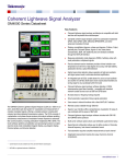
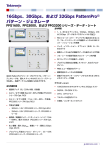
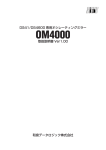
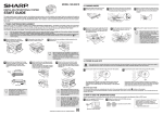
Coherent Lightwave Signal Analyzer Software
OM1106 Software Datasheet
Test automation acquires complete measurements at each channel
Integrated measurement results allow easy channel-to-channel
comparisons
Introduction
A common thread throughout the Tektronix OM-series coherent optical
products is the OM1106 Coherent Optical Analysis Software. This software
is included with all Tektronix OM4000-series optical modulation analyzers
(OMA) and is also available as a stand-alone software package for
customers to use with own OMAs or as a coherent optical research tool.
The OM1106 Coherent Lightwave Signal Analyzer software provides an
ideal platform for research and testing of coherent optical systems. It offers
a complete software package for acquiring, demodulating, analyzing, and
visualizing complex modulated systems from an easy-to-use user interface.
The software performs all calibration and processing functions to enable
real-time burst-mode constellation diagram display, eye-diagram display,
Poincaré sphere, and bit-error detection. Advanced users can take
advantage of the provided MATLAB signal analysis source code and
modify the signal processing algorithms while still taking advantage of the
rich user interface for acquisition, signal visualization, and numerical
measurements.
The OM1106 analysis software consists of a number of major building
blocks. At the heart of the software is a complete library of analysis
algorithms. These algorithms have not been re-purposed from the wireless
communications world: they are specifically designed for coherent optical
analysis, executed in a customer-supplied MATLAB installation.
Key features
The flexibility of the OM1106 software allows it to be used in a number of
different ways. You can make measurements solely through the OUI, you
can use the programmatic interface to and from MATLAB for customized
processing, or you can do both by using the OUI as a visualization and
measurement framework around which you build your own custom
processing.
Complete coherent signal analysis system for polarization-multiplexed
QPSK, QAM, differential BPSK/QPSK, and other advanced modulation
formats
Displays constellation diagrams, phase eye diagrams, Q-factor, Q-plot,
spectral plots, Poincaré Sphere, signal vs. time, laser phase
characteristics, BER, with additional plots and analyses available
through the MATLAB interface 1
The OM1106 software also provides a complete applications programmatic
interface (API) to these algorithms. Using these APIs to provide a
substantial feature set is the OM-Series User Interface (OUI). The OUI
provides a complete coherent optical tool suite allowing any user to conduct
detailed analysis of complex modulated optical signals without requiring
any knowledge of MATLAB, analysis algorithms, or software programming.
Measures polarization mode dispersion (PMD) of arbitrary order with
most polarization multiplexed signals
Smart polarization separation follows signal polarization
User access to internal functions with a direct MATLAB interface
Remote access available through Ethernet
Superior user interface offers comprehensive visualization for ease-ofuse combined with the power of MATLAB
Multi-carrier software option allows user-definable superchannel setup
Superchannel configuration allows user to define number of channels,
channel frequency, and channel modulation format
1
MATLAB is a registered trademark of MathWorks.
www.tektronix.com 1
Datasheet
OM-series user interface (OUI)
The common thread through the Tektronix OM-series products is the OMseries user interface (OUI) software that controls the acquisition and
display of data. This OUI can be ordered separately without the OM4000series optical modulation analyzer for analysis purposes with another
coherent receiver system. The data-capture and analysis only version of
the OUI software is called OM1106.
The OUI provides the user to display all the standard coherent optical
visualizations such as eye diagrams, constellation diagrams, Poincaré
spheres, and so on. The OUI also provides a complete measurement suite
to numerically report key measurements. Constellation measurements
include elongation, real and imaginary bias, magnitude, phase angle, EVM,
and others. Eye diagram measurements include many key time domain
metrics such as eye height, overshoot, undershoot, risetime, falltime, skew,
crossing point, etc. Statistics are provided for all numerical measurements
to facilitate data gathering over longer periods of time.
Get up and running fast with the easy-to-use
OUI
The OUI allows you to easily configure and display your measurements and
also provides software control for third-party applications using WCF
or .NET communication. The OUI can also be controlled from MATLAB or
LabVIEW.
The following image shows a QAM measurement setup. The plots can be
moved, docked, or resized. You can close or create plots to display just the
information you need.
QAM measurements on the OM-series user interface (OUI).
In addition to the numerical measurements provided on the plots, the
measurements are also summarized on the Measurements window where
statistics are also displayed. An example of some of these measurements
is shown in the following figure.
OM-series user interface (OUI) showing color-grade graphics options. Symbols can also
be colored to a key indicating prior state. Data shown is 112 Gb/s PM-QPSK.
OUI showing display of select equivalent-time measurements.
Annotated measurement results table from OUI.
2 www.tektronix.com
OM1106
Make adjustments faster
The OUI is designed to collect data from the oscilloscope and move it into
the MATLAB workspace with extreme speed to provide the maximum data
refresh rate. The data is then processed in MATLAB and the resulting
variables are extracted for display.
Take control with tight MATLAB integration
Since 100% of the data processing occurs in MATLAB, test engineers can
easily probe into the processing to understand each step along the way.
R&D labs can also take advantage of the tight MATLAB integration by
writing their own MATLAB algorithms for new techniques under
development.
Use the optimum algorithm
Don’t worry about which algorithm to use. When you select a signal type in
the OUI (for example, PM-QPSK), the software applies optimal algorithm to
the data for that signal type. Each signal type has a specially designed
signal processing approach that is best for the application. This means that
you can get results right away.
Don’t get stymied by laser phase noise
Signal processing algorithms designed for electrical wireless signals don’t
always work well with the much noisier sources used for complex optical
modulation signals. Our robust signal processing methods tolerate enough
phase noise to even make it possible to test signals which would
traditionally be measured by differential or direct detection such as DQPSK.
Q-plot.
Constellation diagrams
Once the laser phase and frequency fluctuations are removed, the resulting
electric field can be plotted in the complex plane. When only the values at
the symbol centers are plotted, this is called a Constellation Diagram.
When continuous traces are also shown in the complex plane, this is often
called a Phase Diagram. Since the continuous traces can be turned on or
off, we refer to both as the Constellation Diagram. The scatter of the
symbol points indicates how close the modulation is to ideal. The symbol
points spread out due to additive noise, transmitter eye closure, or fiber
impairments. The scatter can be measured by symbol standard deviation,
error vector magnitude, or mask violations.
Find the right BER
Q-plots are a great way to get a handle on your data signal quality.
Numerous BER measurements vs. decision threshold are made on the
signal after each data acquisition. Plotting BER vs. decision threshold
shows the noise properties of the signal. Gaussian noise will produce a
straight line on the Q-plot. The optimum decision threshold and
extrapolated BER are also calculated. This gives you two BER values: the
actual counted errors divided by the number of bits counted, as well as the
extrapolated BER for use when the BER is too low to measure quickly.
Constellation diagram.
www.tektronix.com 3
Datasheet
Constellation measurements
Color features
Measurements made on constellation diagrams are available on the “flyout” panel associated with each graphic window. The measurements
available for constellations are described below.
The Color Grade feature provides an infinite persistence plot where the
frequency of occurrence of a point on the plot is indicated by its color. This
mode helps reveal patterns not readily apparent in monochrome. Note that
the lower constellation groups of the example below have higher EVM than
the top groups. In most cases this indicates that the quadrature modulator
bias was too far toward the positive rail. This is not evident from the
crossing points which are approximately correct. In this case an improperly
biased modulator is concealing an improperly biased driver amp.
Constellation measurements
Measurement
Description
Elongation
The ratio of the Q modulation amplitude to the I
modulation amplitude is a measure of how well balanced
the modulation is for the I and Q branches of a particular
polarization’s signal
Real Bias
Expressed as a percent, this says how much the
constellation is shifted left or right. Real (In-phase) bias
other than zero is usually a sign that the In-phase
Tributary of the transmitter modulator is not being driven
symmetrically at eye center
Imag Bias
Expressed as a percent, this says how much the
constellation is shifted up or down. Imaginary
(Quadrature) bias other than zero is usually a sign that
the Quadrature Tributary of the transmitter modulator is
not being driven symmetrically at eye center
Magnitude
The mean value of the magnitude of all symbols with
units given on the plot. This can be used to find the
relative sizes of the two Polarization Signals
Phase Angle
The transmitter I-Q phase bias. It should normally be 90
StdDev by Quadrant
The standard deviation of symbol point distance from the
mean symbol in units given on the plot. This is displayed
for BPSK and QPSK
EVM (%)
The RMS distance of each symbol point from the ideal
symbol point divided by the magnitude of the ideal
symbol expressed as a percent
EVM Tab
The separate EVM tab shown in the right figure provides
the EVM% by constellation group. The numbers are
arranged to correspond to the symbol arrangement. This
is ideal for setting Transmitter modulator bias. For
example, if the left side groups have higher EVM than
the right side, adjust the In-phase Transmitter modulator
bias to drive the negative rail harder
Mask Tab
The separate Mask tab shown in the right figure provides
the number of mask violations by constellation group.
The numbers are arranged to correspond to the symbol
arrangement. The mask threshold is set in the Engine
window and can be used for pass/fail transmitter testing
4 www.tektronix.com
Color Grade Constellation.
OM1106
Color Grade with fine traces.
Color Key Constellation Points is a special feature that works when not in
Color Grade. In this case the symbol color is determined by the value of the
previous symbol. This helps reveal pattern dependence. Here it shows that
pattern dependence is to blame for the poor EVM on the other groups. The
modulator nonlinearity would normally mask this type of pattern
dependence due to RF cable loss, but here the improper modulator bias is
allowing that to be transferred to the optical signal.
Color Key Constellation – If the prior symbol was in Quadrant 1 (upper right) then the
current symbol is colored Yellow. If the prior symbol was in Quadrant 2 (upper left) then
the current symbol is colored Magenta. If the prior symbol was in Quadrant 3 (lower left)
then the current symbol is colored Light Blue (Cyan). If the prior symbol was in Quadrant
4 (lower right) then the current symbol is colored Solid Blue.
www.tektronix.com 5
Datasheet
Eye diagrams
Eye diagram plots can be selected for appropriate modulation formats.
Supported eye formats include Field Eye, which is simply the real part of
the phase trace in the complex plane, Power Eye which simulates the eye
displayed with a Tektronix oscilloscope optical input, and Diff-Eye, which
simulates the eye generated by using a 1-bit delay-line interferometer. As
with the Constellation Plot you can right-click to choose color options as
well. The Field Eye diagram provides the following measurements:
Additional measurements available for
nonoffset formats
Measurement
Description
Overshoot
The fractional overshoot of the signal. One value is
reported for the tributary, and for a multilevel (QAM)
signal it is the average of all the overshoots
Undershoot
The fractional undershoot of the signal (overshoot of
the negative-going transition)
Risetime
The 10-90% rise time of the signal. One value is
reported for the tributary, and for a multilevel (QAM)
signal it is the average of all the rise times
Falltime
The 90-10% fall time of the signal
Skew
The time relative to the center of the power eye of the
midpoint between the crossing points for a particular
tributary
Crossing Point
The fractional vertical position at the crossing of the
rising and falling edges
Measurements vs. Time
Field eye diagram.
Field eye measurements
Measurement
Description
Q (dB)
Computed from 20 × Log10 of the linear
decision threshold Q-factor of the eye
Eye Height
The distance from the mean 1-level to
the mean 0-level (units of plot)
Rail0 Std Dev
The standard deviation of the 0-level as
determined from the decision threshold
Q-factor measurement
Rail1 Std Dev
The standard deviation of the 1-level as
determined from the decision threshold
Q-factor measurement
In the case of multilevel signals, the above measurements are listed in the
order of the corresponding eye openings in the plot. The top row values
correspond to the top-most eye opening.
In addition to the eye diagram, it is often important to view signals versus
time. For example, it is instructive to see what the field values were doing in
the vicinity of a bit error. All of the plots which display symbol-center values
will indicate if that symbol is errored by coloring the point red (assuming
that the data is synchronized to the indicated pattern). The Measurement
vs. Time plot is particularly useful in this way as it helps to distinguish errors
due to noise, pattern dependence, or pattern errors.
Errored symbol in Measurement vs. Time plot.
The above functions involving Q-factor use the decision threshold method
described in the paper by Bergano 2. When the number of bit errors in the
measurement interval is small, as is often the case, the Q-factor derived
from the bit error rate may not be an accurate measure of the signal quality.
However, the decision threshold Q-factor is accurate because it is based on
all the signal values, not just those that cross a defined boundary.
2
N.S. Bergano, F.W. Kerfoot, C.R. Davidson, “Margin measurements in optical amplifier systems,” IEEE Phot. Tech. Lett., 5, no. 3, pp. 304-306 (1993).
6 www.tektronix.com
OM1106
3D visualization tools
Complex-modulation signals are inherently 3D since in-phase and
quadrature components are being changed vs. time. The 3D Eye Diagram
provides a helpful combination of the Constellation and Eye diagrams into a
single 3D diagram. This helps to visualize how the complex quantity is
changing through the bit period. The diagram can be rotated and scaled.
Also available in 3D is the Poincaré Sphere. The 3D view is helpful when
viewing the polarization state of every symbol. The symbols tend to form
clusters on the Poincaré Sphere which can be revealing to expert users.
The non-normalized Stokes Vectors can also be plotted in this view.
Analysis Controls
The Analysis Controls window allows you to set parameters relevant to the
system and its measurements.
Analysis parameters
Parameter
Description
Frequency
Clock recovery is performed in software, so only a
frequency range of expected clock frequencies is
required
Signal Type
The signal type (such as PM-QPSK) determines the
algorithm used to process the data
Data Patterns
Specifying the known PRBS or user pattern by
physical tributary permits error counting, constellation
orientation, and two-stage phase estimation
User patterns may be assigned in the MATLAB window shown here. The
data pattern can be input into MATLAB or found directly through
measurement of a high SNR signal.
Signal spectra
An FFT of the corrected electric field vs. time can reveal much about the
data signal. Asymmetric or shifted spectra can indicate excessive laser
frequency error. Periodicity in the spectrum shows correlation between data
tributaries. The FFT of the laser phase vs. time data can be used to
measure laser phase noise.
MATLAB window.
Laser Phase Spectrum window
Signal Spectrum window.
www.tektronix.com 7
Datasheet
Poincaré Sphere
Impairment measurement and compensation
Polarization data signals typically start out well aligned to the PM-fiber
axes. However, once in standard single mode fiber, the polarization states
will start to drift. However, it is still possible to measure the polarization
states and determine the polarization extinction ratio. The software locks on
each polarization signal. The polarization states of the two signals are
displayed on a circular plot representing one face of the Poincaré sphere.
States on the back side are indicated by coloring the marker blue. The
degree of orthogonality can be visualized by inverting the rear face so that
orthogonal signals always appear in the same location with different color.
So, Blue means back side (negative value for that component of the Stokes
vector), X means X-tributary, O means Y-tributary, and the Stokes vector is
plotted so that left, down, blue are all negative on the sphere.
When studying transmission implementations, it is important to be able to
compensate for the impairments created by long fiber runs or optical
components. Chromatic Dispersion (CD), and Polarization Mode Dispersion
(PMD) are two important linear impairments that can be measured or
corrected by the OM4000 software. PMD measurement is based on
comparison of the received signal to the back-to-back transmitter signal or
to an ideal signal. This produces a direct measure of the PMD instead of
estimating based on adaptive filter behavior. The user can specify the
number of PMD orders to calculate. Accuracy for 1st-order PMD is ~1 ps at
10 Gbaud. There is no intrinsic limit to the CD compensation algorithm. It
has been used successfully to compensate for many thousands of ps/nm.
InvertedRearFace – Checking this box inverts the rear face of the Poincaré
sphere display so that two orthogonal polarizations will always be on top of
each other.
Recording and playback
You can record the workspace as a sequence of .MAT files using the
Record button in the Offline ribbon. These files are recorded in a default
directory, usually the MATLAB working directory, unless previously
changed. You can play back the workspace from a sequence of .MAT files
by first using the Load button in the Offline Commands section of the Home
ribbon. Load a sequence by marking the files you want to load using the
Ctrl key and marking the filenames with the mouse. You can also load a
contiguous series using the Shift key and marking the first and last
filenames in the series with the mouse. Use the Run button in the Offline
Commands section of the Home ribbon to cycle through the .MAT files you
recorded. All filtering and processing you have implemented occurs on the
recorded files as they are replayed.
Poincaré Sphere window.
Workspace record and playback.
8 www.tektronix.com
OM1106
Multi-carrier superchannel support
User-definable superchannels
Even as 100G coherent optical systems are being deployed, architectures
for 400G and beyond are being proposed and developed. One architecture
gaining prominence is the “superchannel.” The configurations of
superchannels vary considerably. Some proposals call for 400G to be
achieved by 2 carriers of DP-16QAM. Other proposals are for 500 Gb/s
consisting of 10 or more carriers of DP-QPSK. Some of these carriers are
arranged on a standard ITU carrier grid, while others support 12.5 GHz
“grid-less” layouts. Clearly, flexible test tools are needed for such nextgeneration systems. Option MCS to the OM4106D and OM1106 offers the
complete flexibility to carrier out such tests.
For manufacturers getting a jump on superchannels, or researchers
investigating alternatives, user-definable superchannel configurations are a
must. Option MCS allows the user to set up as many carriers within the
superchannel definition as necessary. Each carrier can have an arbitrary
center frequency; no carrier grid spacing is imposed. The carrier center
frequencies can be set as absolute values (in THz) or as relative values (in
GHz).
Multi-carrier setup.
Superchannel spectrum.
Typically, the OUI will retune the OM4106D local oscillator for each carrier.
However, in cases where multiple carriers may fit within the oscilloscope
bandwidth, multiple carriers can be demodulated in software from a
common local oscillator frequency. The user is given the flexibility to specify
the preferred local oscillator frequency for each carrier.
Automated measurements
Once the superchannel is configured, the system can take measurements
on each channel without further intervention by the user. The OUI
automatically tunes the OM4106D local oscillator, takes measurements at
that channel, re-tunes to the next channel, and so forth until measurements
of the entire superchannel have been taken. Results of each channel are
displayed in real-time and persist after all measurements are made for easy
comparison.
Multi-carrier measurements.
www.tektronix.com 9
Datasheet
Integrated measurement results
Interaction between OUI and MATLAB
All of the same measurement results that are made for single channels are
also available for individual channels in a superchannel configuration.
Additionally, multi-carrier measurement results are available side-by-side
for comparison between channels. Visualizations such as eye diagrams,
constellation diagrams, and optical spectrum plots can be viewed a single
channel at a time, or with all channels superimposed for fast comparison.
For separating channels in a multi-carrier group, several different filters can
be applied, including raised cosine, Bessel, Butterworth, Nyquist, and userdefined filters. These filters can be any order or roll-off factor and track the
signal frequency.
The OUI takes information about the signal provided by the user together
with acquisition data from the oscilloscope and passes them to the
MATLAB workspace, shown in Figure 3. A series of MATLAB scripts are
then called to process the data and produce the resulting field variables.
The OUI then retrieves these variables and plots them. Automated tests
can be accomplished by connecting to the OUI or by connecting directly to
the MATLAB workspace.
The user does not need any familiarity with MATLAB; the OUI can manage
all MATLAB interactions. However, advanced users can access the
MATLAB interface internal functions to create user-defined demodulators
and algorithms, or for custom analysis visualization.
Coherent optical signal generation
Tektronix offers several signal generation instruments capable of
generating coherent optical waveforms. The AWG70000 Series Arbitrary
Waveform Generators (AWG) and the PPG3000 Series Programmable
Pattern Generators offer the flexibility to choose the type of signal
generation instrument suited to the test requirements.
The AWG70000 Series can reach sampling rates as high as 50GSa/s with
10 bits vertical resolution. This level of performance allows for the direct
generation of IQ basebands signals required by modern coherent optical
communication systems. The arbitrary waveform generation capabilities of
the AWG70000 Series makes it possible to create multi-level signals such
as 16QAM or 64QAM, add impairments to a signal, or to create waveforms
that are pre-compensated for the real-world effects of the test system.
The PPG3000 Series can generate patterns up to 32 Gb/s and offers 1, 2,
or 4 channels in a single instrument. The patterns can be standard PRBS
patterns or user-defined. Using a 4-channel pattern generator makes
creating dual-polarization I-Q waveforms very simple.
Coherent optical signal generation is one of the more demanding
applications for an AWG. The requirements in terms of number of channels
sampling rate, bandwidth, record length, and timing and synchronization
quality can be only met by the highest performance instruments, such as
the Tektronix AWG70000 series. The unique capability of generating ideal
or distorted signals, and the ease to add new modulation schemes and
signal processing algorithms without the need to add any extra hardware,
make AWGs an ideal tool for coherent optical communication research and
development.
OUI/MATLAB data flow
Signal processing approach
For real-time sampled systems, the first step after data acquisition is to
recover the clock and retime the data at 1 sample per symbol at the symbol
center for the polarization separation and following algorithms (shown as
upper path in the figure). The data is also re-sampled at 10X the baud rate
(user settable) to define the traces that interconnect the symbols in the eye
diagram or constellation (shown as the lower path).
The clock recovery approach depends on the chosen signal type. Laser
phase is then recovered based on the symbol-center samples. Once the
laser phase is recovered, the modulation part of the field is available for
alignment to the expected data for each tributary. At this point bit errors can
be counted by looking for the difference between the actual and expected
data after accounting for all possible ambiguities in data polarity. The
software selects the polarity with the lowest BER. Once the actual data is
known, a second phase estimate can be done to remove errors that may
result from a laser phase jump. Once the field variables are calculated, they
are available for retrieval and display by the OUI.
At each step the best algorithms are chosen for the specified data type,
requiring no user intervention unless desired.
10 www.tektronix.com
OM1106
Data flow through the “Core Processing” engine.
Signal processing customization
The OM1106 software includes the MATLAB source code for the
"CoreProcessing" engine (certain proprietary functions are provided as
compiled code). You can customize the signal processing flow, or insert or
remove processes as desired. Alternatively, you can remove all Tektronix
processing and completely replace it with your own. By using the existing
variables defined for the data structures, you can then see the results of
analysis processing using the rich visualizations provided by the OUI. This
allows you to focus your time on algorithms rather than on tasks such as
acquiring data from the oscilloscope or displaying constellation diagrams.
Dynamic MATLAB integration
Customizing the CoreProcessing algorithms provide an excellent way
conduct signal processing research. In order to speed up development of
signal processing the OM-Series User Interface (OUI) provides a dynamic
Matlab integration window. Any Matlab code typed in this window is
executed on every pass through the signal processing loop. This allows you
to quickly add or "comment out" function calls, write specific values into
data structures, or modify signal processing parameters on the fly without
having to stop the processing loop or modify the Matlab source code.
www.tektronix.com 11
Datasheet
CoreProcessing functions
The following are some of the CoreProcessing functions used to analyze
the coherent signal. Full details on these functions, their use in the
processing flow, and the MATLAB variable used, are available in the
OM1106 user manual.
EstimateClock determines the symbol clock frequency of a digital
data-carrying optical signal based on oscilloscope waveform records.
The scope sampling rate may be arbitrary (having no integer
relationship) compared to the symbol rate.
ClockRetime forms an output parameter p, representing a dualpolarization signal vs. time, from four oscilloscope waveforms V. The
output p is retimed to be aligned with the timing grid specified by Clock.
EstimateSOP reports the state of polarization (SOP) of the tributaries
in the optical signal. The result is provided in the form of an orthogonal
(rotation) matrix RotM. For a polarization multiplexed signal the first
column of RotM is the SOP of the first tributary, and the second column
the SOP of the second tributary. For a single tributary signal, the first
column is the SOP of the tributary, and the second column is
orthogonal to it. The signal is transformed into its basis set (the
tributaries horizontal vertical polarizations) by multiplying by the inverse
of RotM.
EstimatePhase estimates the phase of the optical signal. The
algorithm used is known to be close to the optimal estimate of the
phase. The algorithm first determines the heterodyne frequency offset
and then estimates the phase. The phase reported in the .Values field
is after the frequency offset has been subtracted.
ApplyPhase multiplies the values representing a single or dual
polarization parameters vs. time by a phase factor to give a resulting
set of values.
AlignTribs performs ambiguity resolution. The function acts on
variable which is already corrected for phase and state of polarization,
but for which the tributaries have not been ordered. AlignTribs uses the
data content of the tributaries to distinguish between them. AlignTribs
processes the data patterns in order according to the modulation
format, starting with X-I. For each pattern it tries to match the given
data pattern with the available tributaries of the signal. If the same
pattern is used for more than one tributary, the relative pattern delays
will be used to distinguish between them.
The use of delay as a secondary condition to distinguish between
tributaries means that AlignTribs will work with transmission
experiments that use a single data pattern generator which is split
several ways with different delays. The delay search is performed only
over a limited range of 1000 bits in the case of PRBS patterns, so this
method of distinguishing tributaries will not usually work when using
separate data pattern generators programmed with the same PRBS.
Spect estimates the power spectral density of the optical signal using a
discrete Fourier transform. It can take any many of our time waveforms
as input such as corrected oscilloscope input data, front-end processed
data, polarization separated data, averaged data, and FIR data. It can
also apply Hanning or Flat-Top window filters and produce the desired
resolution bandwidth over a set frequency range.
GenPattern generates a sequence of logical values, 0s and 1s, given
an exact data pattern. The exact pattern specifies not only the form of
the sequence but also the place it starts and the data polarity. The data
pattern specified may be a pseudo-random bit sequence (PRBS) or a
specified sequence.
LaserSpectrum estimates the power spectral density of the laser
waveform in units of dBc. The function LaserSpectrum takes
ThetaSym, the estimated relative laser phase sampled at the symbol
rate, as input and defines the frequency centered laser waveform. This
waveform is then scaled by a hamming window, and the power spectral
density of the waveform is estimated as the discrete Fourier transform
of this signal.
QDecTh uses the decision threshold method to estimate the Q-factor
of a component of the optical signal. The method is useful because it
quickly gives an accurate estimate of Q-factor (the output signal-tonoise ratio) even if there are no bit errors, or if it would take a long time
to wait for a sufficient number of bit errors.
Supported measurements and display tools
Characteristic
Description
Real-time supported
feature
Equivalent time
supported feature
Constellation Diagram
Constellation diagram accuracy including intradyne and demodulation
error can be measured by the RMS error of the constellation points
divided by the magnitude of the electric field for each polarization signal
X
X
Constellation Elongation
Ratio of constellation height to width
X
X
Constellation Phase Angle
Measure of transmitter IQ phase angle
X
X
Constellation I and Q Bias
Measure of average symbol position relative to the origin
X
X
Constellation Mask
User-settable allowed EVM level. Symbols violating the mask are
counted
X
X
Eye Decision Threshold Q-factor
The actual Q achieved will depend on the quality of the data signal, the
signal amplitude, and the oscilloscope used for digitalization. Using the
Tektronix DPO73304D oscilloscope (4-Ch), a Q-factor of 20 dB is
achievable at 40 GBaud
X
X
12 www.tektronix.com
OM1106
Characteristic
Description
Real-time supported
feature
Equivalent time
supported feature
Decision Threshold Q-plot
Displays BER vs. decision threshold for each eye opening. The Q value
at optimum decision threshold is the Q-factor
X
X
Signal Spectrum and Laser Spectrum
Display of signal electric field vs. time in the complex plane FFT of power X
signal or laser phase noise
MATLAB Window
Commands may be entered that execute each time signals are acquired
and processed
X
X
Measurements vs. Time
Optical field, symbol-center values, errors, and averaged waveforms are
displayed vs. time in the OUI; any parameter can be plotted vs. time
using the appropriate MATLAB expression
X
X
3D Measurements
3D Eye (complex field values vs. time), and 3D Poincaré Sphere for
symbol and tributary polarization display
X
Differential Eye Diagram Display
Balanced or single-ended balanced detection is emulated and displayed
in the Differential Eye Diagram
X
Frequency Offset
Frequency offset between signal and reference lasers is displayed in
Measurement panel
X
Poincarè Sphere
Polarizations of the Pol-muxed signal tributaries are tracked and
displayed on the Poincaré Sphere. PER is measured
X
X
Signal Quality
EVM, Q-factor, and mask violations
X
X
Tributary Skew
A time offset for each tributary is reported in the Measurement panel
X
X
CD Compensation
No intrinsic limit for offline processing – FFT-based filter to remove CD in X
frequency domain based on a given dispersion value
PMD Measurement
PMD values are displayed in the Measurement panel for Polarizationmultiplexed formats with a user-specified number of PMD orders
X
Oscilloscope and/or Cable Delay Compensation Cable, oscilloscope, and receiver skew is corrected through interpolation ±0.5 ns
in the OUI. Additional cable adjustment is available using the oscilloscope
UI
Oscilloscope Skew Adjustment
Equivalent-time oscilloscope skew is adjusted using the "Delay" feature in
the supported sampling head plug-ins
±100%
Calibration Routines
Receiver Skew, DC Offset, and Path Gain Mismatch Hybrid angle and
state of polarization are factory calibrated
X
X
Data Export Formats
MATLAB (other formats available through MATLAB or ATE interface);
PNG
X
X
Raw Data Replay with Different Parameter
Setting
Movie mode and reprocessing
X
X
Bit Error Ratio Measurements
Number of counted bits/symbols
X
X
Number or errors detected
X
X
Bit error ratio
X
X
Differential-detection errors
X
X
Save acquisition on detected error
X
X
Offline Processing
Run software on a separate PC or on the oscilloscope
X
X
Coherent Eye Diagram
Shows the In-Phase or Quadrature components vs. time modulo two bit
periods.
X
X
Power Eye Diagram
Shows the computed power per polarization vs time modulo 2 bit periods. X
X
www.tektronix.com 13
Datasheet
System requirements
Supported platforms for the OM1106 software (OUI):
Computer with nVidia graphics card running US Windows 7 64-bit and MATLAB 2011b (64-bit)
Computer with nVidia graphics card running US Windows XP 32-bit and MATLAB 2009a (32-bit)
The following platforms are supported but may not be able to use certain advanced graphics features such as color grade and 3D:
Tektronix 70000 Series Oscilloscopes running Windows 7 64-bit and MATLAB 2011b (64-bit)
Computer with non-nVidia graphics running US Windows 7 64-bit and MATLAB 2011b (64-bit)
Computer with non-nVidia graphics running US Windows XP 32-bit and MATLAB 2009a (32-bit)
Please check with Tektronix when ordering for the most up-to-date requirements including support for the latest releases of MATLAB software.
Please contact Tektronix for a price quote or to arrange a demonstration. All product descriptions and specifications are subject to change without notice.
14 www.tektronix.com
OM1106
Ordering information
Signal analyzer software
OM1106
Coherent Lightwave Signal Analyzer software
OM1106 options
OM1106
OUI signal analysis software only
OM1106 QAM
Adds QAM and other software demodulators
OM1106 MCS
Adds multi-carrier superchannel support
OM1106 L0
English manual
OM11UP
Upgrade kits to the Coherent Lightwave Signal Analyzer Software:
OM11UP MCS
Adds Multi-carrier (superchannel) support
OM11UP QAM
Adds QAM and other software demodulators
OM11UP SHIP
Customer Requests Shipment or Export Requirement
OMADDLSW
Adds additional seat of Coherent Lightwave Signal Analyzer Software
Related products
23 GHz optical modulation analyzer
OM4006D
23 GHz Coherent Lightwave Signal Analyzer (requires choice of lasers)
OM4006D CC
C-band lasers (receiver tested over C-band)
OM4006D LL
L-band lasers (receiver tested over L-band)
OM4006D CL
Coupled C- and L-band lasers (receiver calibrated over Cand L-band)
OM4006D NL
No lasers (receiver calibrated over C- and L-band)
OM4006D EXT
Adds external connections for reference laser
OM406D QAM
Adds QAM and other software demodulators
OM4006D MCS
Adds multi-carrier superchannel support
33 GHz optical modulation analyzer
OM4106D
33 GHz Coherent Lightwave Signal Analyzer (requires choice of lasers):
OM4106D CC
C-band lasers (receiver tested over C-band)
OM4106D LL
L-band lasers (receiver tested over L-band)
OM4106D CL
Coupled C- and L-band lasers (receiver calibrated over Cand L-band)
OM4106D NL
No lasers (receiver calibrated over C- and L-band)
OM4106D EXT
Adds external connections for reference laser
OM4106D QAM
Adds QAM and other software demodulators
OM4106D MCS
Adds multi-carrier superchannel support
www.tektronix.com 15
Datasheet
Coherent optical transmitter
OM5110
46 GBaud Dual-Polarization Coherent Optical IQ Transmitter
OM5110 C
C-band laser factory installed
OM5110 L
L-band laser factory installed
OM5110 NL
No laser installed, requires external laser
Coherent receiver calibration source
OM2210
33 GHz Coherent Lightwave Signal Analyzer (requires choice of lasers):
OM2210 C
C-Band Coherent Receiver Calibration Source (with single C-band laser)
OM2210 CC
C-Band Coherent Receiver Calibration Source (with two C-band lasers)
OM2210 L
L-Band Coherent Receiver Calibration Source (with single L-band laser)
OM2210 LL
L-Band Coherent Receiver Calibration Source (with two L-band lasers)
OM2210 CL
C + L-Band Coherent Receiver Calibration Source (with coupled C and L lasers)
OM2210 NL
Receiver calibrated over C+L
C-Band & L-Band laser sources
OM2012
nLaser (requires choice of laser configuration):
OM2012 CC
C-Band nLaser (with two C-band lasers)
OM2012 CL
C + L-Band nLaser (with one C-band laser and one L-band laser)
OM2012 LL
L-Band nLaser (with two L-band lasers)
Tektronix is registered to ISO 9001 and ISO 14001 by SRI Quality System Registrar.
Product Area Assessed: The planning, design/development and manufacture of electronic Test and Measurement instruments.
ASEAN / Australasia (65) 6356 3900
Belgium 00800 2255 4835*
Central East Europe and the Baltics +41 52 675 3777
Finland +41 52 675 3777
Hong Kong 400 820 5835
Japan 81 (3) 6714 3010
Middle East, Asia, and North Africa +41 52 675 3777
People's Republic of China 400 820 5835
Republic of Korea 001 800 8255 2835
Spain 00800 2255 4835*
Taiwan 886 (2) 2656 6688
Austria 00800 2255 4835*
Brazil +55 (11) 3759 7627
Central Europe & Greece +41 52 675 3777
France 00800 2255 4835*
India 000 800 650 1835
Luxembourg +41 52 675 3777
The Netherlands 00800 2255 4835*
Poland +41 52 675 3777
Russia & CIS +7 (495) 6647564
Sweden 00800 2255 4835*
United Kingdom & Ireland 00800 2255 4835*
Balkans, Israel, South Africa and other ISE Countries +41 52 675 3777
Canada 1 800 833 9200
Denmark +45 80 88 1401
Germany 00800 2255 4835*
Italy 00800 2255 4835*
Mexico, Central/South America & Caribbean 52 (55) 56 04 50 90
Norway 800 16098
Portugal 80 08 12370
South Africa +41 52 675 3777
Switzerland 00800 2255 4835*
USA 1 800 833 9200
* European toll-free number. If not accessible, call: +41 52 675 3777
For Further Information. Tektronix maintains a comprehensive, constantly expanding collection of application notes, technical briefs and other resources to help engineers working on the cutting edge of technology. Please visit www.tektronix.com.
Copyright © Tektronix, Inc. All rights reserved. Tektronix products are covered by U.S. and foreign patents, issued and pending. Information in this publication supersedes that in all previously published material. Specification and
price change privileges reserved. TEKTRONIX and TEK are registered trademarks of Tektronix, Inc. All other trade names referenced are the service marks, trademarks, or registered trademarks of their respective companies.
13 Jan 2015
www.tektronix.com
85W-31037-0