1
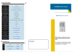
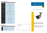
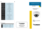
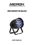
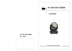
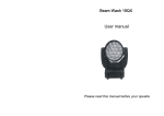
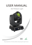
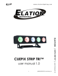
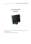
USER MANUAL
19pcs LED Bee Eyes Beam Light
Please Read Over This Manual Before Operating The Light Fixture
1 PRODUCT SPECIFICATIONS
1.1 PRODUCT SPECIFICATIONS
The MB1915 has 19pcs 15w 4-in-1 LEDs , with the functions of beam, image, wash,
spinning shadow. The biggest advantage is “single pixel LED”, bringing the amazing effect.
• Voltage:AC90~260V 50/60Hz
• Max Power:300W
•Compact Intelligent Moving Head Fixture
•19X15w Led Source
•17/52-Channel DMX Control Modes
•4-button LCD Control Panel
•Pan:540°/Tilt:270°(8-16Bit Resolution)
•Variable Electronic Dimmer(0-100%)
•Multiple Built-in Auto & Sound Activated Programs
•Cooling System: Forced Convection Cooling
•Housing: Flame-Retardant Plastic(V0)
•Modes: DMX-512, Auto, Sound Active & Master-Slave
•Dimension:300x200x370mm
•Weight:8kg
370
375
200
300
.1.
1.2
PRODUCT FEATURES
Up
Menu Down
Enter
Menu - This button is used for accessing the menu functions.
Down – The down button is used for toggling down or back through the menu
functions and settings
Up – The up button is used for toggling forward through the menu functions and
settings.
Enter – The enter button is used for entering into a certain menu function or
locking a function into memory.
DMX output DMX input
Power output Power input Switch
Fuse Holder
Be sure to follow the above figure when making your own cables. Do not use the ground
plug on the XLR connector. Do not connect the cable’s shield conductor to the ground plug
or allow the shield conductor to come in contact with the XLR’s outer casing. Grounding
the shield could cause a short circuit and erratic behavior.
.2.
2 INSTALLATION
2.1
MOUNTING:
●The fixture can be mounted in any position.
●Always ensure that mounting surface can withstand 10 times the weight of the
fixture.
●Always use a safety cable when mounting the fixture in any elevated position.
HANGING
UPRIGHT
CAUTION!
Be sure a qualified electrician performs all electrical
connections.
IMPORTANT SAFETY NOTE!!!
Always use a safety cable when installing this unit!!
Be sure that the safety cable is connected to a solid load-bearing structure.
.3.
CLAMP
2.2
FUSE REPLACEMENT
● Remove the safety cap by a screwdriver.
● Fetch the old fuse from safety cap.
FUSE
● Install a new fuse.
● Install the safety cap.
● Fuse:3A,250V
SAFTY CAP
.
2.3
SAFETY WARNING
IMPORTANT
【ALWAYS READ THE USER MANUAL BEFORE OPERATION. 】
【PLEASE CONFIRM THAT THE POWER SUPPLY STATED ON THE
PRODUCT IS THE SAME AS THE MAINS POWER SUPPLY IN YOUR AREA.】
● This product must be installed by a qualified professional person.
● Always operate the equipment as described in the user manual.
● A minimum distance of 0.5m must be maintained between the equipment and combustible surface.
● The product must always be placed in a well ventilated area.
● Always make sure that the equipment is installed securely.
● Do not stand close to the equipment and stare directly into the LED light source.
● Always disconnect the power supply before attempting and maintenance.
● Always make sure that the supporting structure is solid and can support the combined weight of the
products.
● The earth wire must always be connected to the ground.
● Do not touch the power cables if your hands are wet.
ATTENTION
● This product left the place of manufacturer in perfect condition. In order to maintain this
condition and for safe operation, the user must always follow the instructions and safety
warnings described in this user manual.
● Avoid shaking or strong impacts to any part of the equipment.
● Make sure that all parts of the equipment are kept clean and free of dust.
● Always make sure that the power connections are connected correct and secure.
● If there is any malfunction of the equipment, contact us immediately.
● When transferring the product, it is advisable to use the original packaging in which the
product left the factory.
● Shields, lens or ultraviolet screens should be changed if they have become damaged to such
an extent that their effectiveness is impaired.
● The lamp (LED) should be changed if it has become damaged or thermally deformed.
.4.
3 DISPLAY PANEL OPERATION
3.1.Graphic Section
MENU
DOWN
UP
ENTER
【MENU 】Scroll through the main menu or exit from the current sub-menu
【ENTER】Enter the currently selected menu or confirm the current function
value
【DOWN】Scroll 'DOWN' through the menu list or decrease the value of the
current function
【 UP 】Scroll 'UP' through the menu list or increase the value of the
Current function
3.2.LCD Display Window Table
1 . DMX512 ADDRESS 001
Press UP and DOWN to adjust the address code,
press the OK to save.
.5.
2.ADJ COLOR LIGHT
Press UP and DOWN to adjust the color brightness,
press the OK to save.
ADJ RED LIGHT
ADJ GREEN LIGHT
ADJ BLUE LIGHT
ADJ WHITE LIGHT
0~255
0~255
0~255
0~255
3.SET FOCUS
Press UP and DOWN to adjust the focus,
press the OK to save .
0~127
.6.
4.SIDE PROGRAM
Press UP and DOWN to set side program,
press the OK to save.
0~36
5.ADJUST SPEED
Press UP and DOWN to set ajust speed,
press the OK to save .
0~16
6.TEST MODE
Press UP and DOWN to set test mode,
press the OK to save.
.7.
7.X-motor reversal?
Press UP and DOWN to choose whether X-motor reversal or not.
8.Y-motor reversal?
Press UP and DOWN to choose whether Y-motor reversal or not.
9.Reset?
Press OK to display reset process.
.8.
10.SELECT LANGUAGE
Press UP and DOWN to choose CHINESS or ENGLISH.
CHINESE
ENGLISH
11.DMX-MODE
Press UP and DOWN to choose DMX-mode,
press the OK to save .
17CH
52CH
.9.
4.Channel Mode
1、17CH MODE
CHANNEL
1
2
3
4
VALUE
FUNCTION
0
255
PAN
0~540°
0
255
TILT
0~270°
0
255
PAN FINE
Fine control of tilt movement 0~3°
0
255
TILT FINE
Fine control of tilt movement 0~3°
Effect Rotation
5
Disc is placed
Rotating disc Promise
0
127
128
255
6
0
255
PAN/TILT SPEED
From fast to slow
7
0
255
DIMMER
8
0
255
STROBE
9
0
255
Red
10
0
255
Green
11
0
255
Blue
12
0
255
White
ZONE
13
0
55
56
75
76
95
96
115
116
135
136
155
156
175
176
195
196
215
216
235
236
255
ALL ZONE
ZONE 1
ZONE 2
ZONE 3
ZONE 4
ZONE 5
ZONE 6
GOBO 7
ZONE 8
ZONE 9
ZONE 10
COLOR MACRO
14
0
20
21
40
41
60
61
80
81
100
101
120
121
140
141
160
161
200
201
220
221
255
R+G++
R+B++
G+R++
G+B++
B+G++
R+G+B++
R+B+G++
B+G+R++
:R+B+G++
B+G+R++
R+B+G++
.10.
VALUE
CHANNEL
FUNCTION
15
0
255
AUTO
16
0
255
AUTO SPEED
CONTROL
0
17
65
129
193
64
128
192
255
No function (After 10S move light show board curve is preferred)
Auto Program
Sound
Reset
2.52CH MODE
CHANNEL
1
2
3
4
VALUE
FUNCTION
0
255
PAN
0~540°
0
255
TILT
0~270°
0
255
PAN FINE
Fine control of tilt movement 0~3°
0
255
TILT FINE
Fine control of tilt movement 0~3°
Effect Rotation
5
Disc is placed
Rotating disc Promise
0
127
128
255
6
0
255
PAN/TILT SPEED
From fast to slow
7
0
255
DIMMER
8
0
255
STROBE
9
0
255
Red 1
10
0
255
Green 1
11
0
255
Blue 1
12
0
255
WHITE 1
13
0
255
Red 2
14
0
255
Green 2
15
0
255
Blue 2
16
0
255
WHITE 2
17
0
255
Red 3
18
0
255
Green 3
19
0
255
Blue 3
20
21
0
255
WHITE 3
0
255
Red 4
22
0
255
Green 4
23
0
255
Blue 4
0
255
WHITE 4
24
.11.
CHANNEL
VALUE
FUNCTION
25
0
255
26
0
255
Green 5
27
0
255
Blue 5
28
0
255
WHITE 5
29
0
255
Red 6
30
0
255
Green 6
31
0
255
Blue 6
32
0
255
WHITE 6
33
0
255
Red 7
34
0
255
Green 7
35
0
255
Blue 7
36
37
0
255
WHITE 7
0
255
Red 8
38
0
255
Green 8
39
0
255
Blue 8
40
0
255
WHITE 8
41
0
255
Red 9
42
0
255
Green 9
43
0
255
Blue 9
44
45
0
255
WHITE 9
0
255
Red 10
46
0
255
Green 10
47
0
255
Blue 10
48
0
255
WHITE 10
Red 5
COLOR MACRO
49
0
20
21
40
41
60
61
80
81
100
101
120
121
140
141
160
161
200
201
220
221
255
R+G++
R+B++
G+R++
G+B++
B+G++
R+G+B++
R+B+G++
B+G+R++
:R+B+G++
.11.
B+G+R++
R+B+G++
50
0
255
AUTO
51
0
255
AUTO SPEED
CONTROL
0
52
65
129
193
64
128
192
255
No function (After 10S move light show board curve is preferred)
Auto Program
Sound
Reset
.12.
CHANNEL
VALUE
FUNCTION
COLOR MACRO
49
0
20
21
40
41
60
61
80
81
100
101
120
121
140
141
160
161
200
201
220
221
255
R+G++
R+B++
G+R++
G+B++
B+G++
R+G+B++
R+B+G++
B+G+R++
R+B+G++
B+G+R++
R+B+G++
50
0
255
AUTO
51
0
255
AUTO SPEED
CONTROL
0
52
65
129
193
64
128
192
255
No function (After 10S move light show board curve is preferred)
Auto Program
Sound
Reset
.13.