1
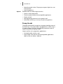
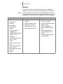
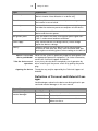
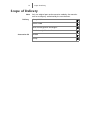
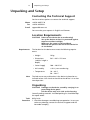
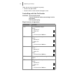
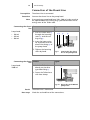
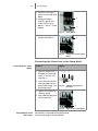
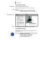
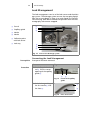
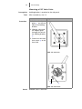
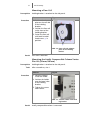
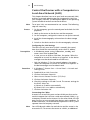
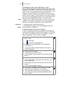
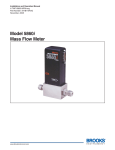
Pump P 2.1L User manual V6840A HPLC 3 Table of Contents Table of Contents Note For your own safety, read the manual and always observe the warnings and safety information on the device and in the manual! Intended Use . . . . . . . . . . . . . . . . . . . . . . . . . . . . . . . . . . . . . . . . . . . . . . . 6 Device Overview . . . . . . . . . . . . . . . . . . . . . . . . . . . . . . . . . . . . . . . . . . . . . . . . 6 Features . . . . . . . . . . . . . . . . . . . . . . . . . . . . . . . . . . . . . . . . . . . . . . . . . . . . . . 6 Pump Heads . . . . . . . . . . . . . . . . . . . . . . . . . . . . . . . . . . . . . . . . . . . . . . . . . . . 7 Eluents . . . . . . . . . . . . . . . . . . . . . . . . . . . . . . . . . . . . . . . . . . . . . . . . . . . . . . . 8 Safety for Users . . . . . . . . . . . . . . . . . . . . . . . . . . . . . . . . . . . . . . . . . . . . . 9 Definition of Personal and Material Damages . . . . . . . . . . . . . . . . . . . . . . . . . 10 Symbols and Signs . . . . . . . . . . . . . . . . . . . . . . . . . . . . . . . . . . . . . . . . . . 11 Scope of Delivery . . . . . . . . . . . . . . . . . . . . . . . . . . . . . . . . . . . . . . . . . . . 12 Unpacking and Setup . . . . . . . . . . . . . . . . . . . . . . . . . . . . . . . . . . . . . . . 13 Contacting the Technical Support . . . . . . . . . . . . . . . . . . . . . . . . . . . . . . . . . . 13 Location Requirements . . . . . . . . . . . . . . . . . . . . . . . . . . . . . . . . . . . . . . . . . . 13 Unpacking . . . . . . . . . . . . . . . . . . . . . . . . . . . . . . . . . . . . . . . . . . . . . . . . . . . . 13 Ports on the Rear Side . . . . . . . . . . . . . . . . . . . . . . . . . . . . . . . . . . . . . . . . . . . 14 Controlling with the Pin Header . . . . . . . . . . . . . . . . . . . . . . . . . . . . . . . . . 15 Plug Connector Assignments . . . . . . . . . . . . . . . . . . . . . . . . . . . . . . . . . . . 15 Analog Control . . . . . . . . . . . . . . . . . . . . . . . . . . . . . . . . . . . . . . . . . . . . . . 17 Initial Startup . . . . . . . . . . . . . . . . . . . . . . . . . . . . . . . . . . . . . . . . . . . . . . 18 Connecting the Piston Backflushing . . . . . . . . . . . . . . . . . . . . . . . . . . . . . . . . 18 Eluent Inlet . . . . . . . . . . . . . . . . . . . . . . . . . . . . . . . . . . . . . . . . . . . . . . . . . . . 19 Connecting the Eluent Inlet to the Pump Head . . . . . . . . . . . . . . . . . . . . . . 19 Connection of the Eluent Line . . . . . . . . . . . . . . . . . . . . . . . . . . . . . . . . . . . . . 20 Changing the Setup to LPG . . . . . . . . . . . . . . . . . . . . . . . . . . . . . . . . . . . . . . . 21 Mounting the Valve Block . . . . . . . . . . . . . . . . . . . . . . . . . . . . . . . . . . . . . . 21 Connecting the Eluent Line to the Pump Head . . . . . . . . . . . . . . . . . . . . . . 22 Venting the Pump . . . . . . . . . . . . . . . . . . . . . . . . . . . . . . . . . . . . . . . . . . . . . . 23 Using PEEK Fittings . . . . . . . . . . . . . . . . . . . . . . . . . . . . . . . . . . . . . . . . . . . . . 23 Leak Management . . . . . . . . . . . . . . . . . . . . . . . . . . . . . . . . . . . . . . . . . . . . . 24 Connecting the Leak Management . . . . . . . . . . . . . . . . . . . . . . . . . . . . . . . 24 Setting the Leak Sensor . . . . . . . . . . . . . . . . . . . . . . . . . . . . . . . . . . . . . . . . 25 Deactivating the Leak Sensor . . . . . . . . . . . . . . . . . . . . . . . . . . . . . . . . . . . 25 Eliminating the Leak . . . . . . . . . . . . . . . . . . . . . . . . . . . . . . . . . . . . . . . . . . 25 V6840A 4 Table of Contents Holding Bracket . . . . . . . . . . . . . . . . . . . . . . . . . . . . . . . . . . . . . . . . . . . . . . . 26 Attaching a Holding Bracket to the Side Panel . . . . . . . . . . . . . . . . . . . . . . 27 Mounting a KNAUER Valve . . . . . . . . . . . . . . . . . . . . . . . . . . . . . . . . . . . . . 28 Mounting a VICI Valco Valve . . . . . . . . . . . . . . . . . . . . . . . . . . . . . . . . . . . . 29 Mounting a VICI Valco valve drive . . . . . . . . . . . . . . . . . . . . . . . . . . . . . . . 30 Mounting a Flow Cell . . . . . . . . . . . . . . . . . . . . . . . . . . . . . . . . . . . . . . . . . 31 Mounting the Axially Compressible Column Vertex Plus AX (20 mm/30 mm) 31 Control the Devices with a Computer in a Local Area Network (LAN) . . . . . . . 32 Configuring the LAN Settings . . . . . . . . . . . . . . . . . . . . . . . . . . . . . . . . . . . 32 Connecting the Cables . . . . . . . . . . . . . . . . . . . . . . . . . . . . . . . . . . . . . . . . 32 Configuring the Router . . . . . . . . . . . . . . . . . . . . . . . . . . . . . . . . . . . . . . . . 33 Integrating the LAN into a Company Network . . . . . . . . . . . . . . . . . . . . . . 33 Controlling Several Systems Separately in a LAN . . . . . . . . . . . . . . . . . . . . . 34 Troubleshooting for Connection Problems . . . . . . . . . . . . . . . . . . . . . . . . . 34 Switching On the Pump . . . . . . . . . . . . . . . . . . . . . . . . . . . . . . . . . . . . . . . . . 36 Flushing the Pump . . . . . . . . . . . . . . . . . . . . . . . . . . . . . . . . . . . . . . . . . . . . . 36 Operation . . . . . . . . . . . . . . . . . . . . . . . . . . . . . . . . . . . . . . . . . . . . . . . . . 38 Control with Chromatography Software . . . . . . . . . . . . . . . . . . . . . . . . . . . . . 38 Control with Control Unit . . . . . . . . . . . . . . . . . . . . . . . . . . . . . . . . . . . . . . . . 38 Meaning of the LEDs . . . . . . . . . . . . . . . . . . . . . . . . . . . . . . . . . . . . . . . . . . . . 38 Installation Qualification (IQ) . . . . . . . . . . . . . . . . . . . . . . . . . . . . . . . . . 40 Operation Qualification (OQ) . . . . . . . . . . . . . . . . . . . . . . . . . . . . . . . . . 40 Test Intervals . . . . . . . . . . . . . . . . . . . . . . . . . . . . . . . . . . . . . . . . . . . . . . . . . . 40 Execution . . . . . . . . . . . . . . . . . . . . . . . . . . . . . . . . . . . . . . . . . . . . . . . . . . . . 40 Maintenance and Care. . . . . . . . . . . . . . . . . . . . . . . . . . . . . . . . . . . . . . . 41 Switching Off the Pump . . . . . . . . . . . . . . . . . . . . . . . . . . . . . . . . . . . . . . . . . 41 Contact with the Technical Support . . . . . . . . . . . . . . . . . . . . . . . . . . . . . . . . 41 Technical Support Hotline: . . . . . . . . . . . . . . . . . . . . . . . . . . . . . . . . . . . . . 41 Maintenance Contract . . . . . . . . . . . . . . . . . . . . . . . . . . . . . . . . . . . . . . . . . . . 41 What maintenance tasks can users perform on the device? . . . . . . . . . . . . . . . 41 Screw Fittings on the Pump Head . . . . . . . . . . . . . . . . . . . . . . . . . . . . . . . . . . 42 Leaks in the Capillary Screw Fittings . . . . . . . . . . . . . . . . . . . . . . . . . . . . . . . . 42 Replacing the Pump Head . . . . . . . . . . . . . . . . . . . . . . . . . . . . . . . . . . . . . . . . 42 Dismounting the Pump Head . . . . . . . . . . . . . . . . . . . . . . . . . . . . . . . . . . . 42 Attaching Capillaries to the Pump Head . . . . . . . . . . . . . . . . . . . . . . . . . . . . . 43 Maintaining the Check Valves . . . . . . . . . . . . . . . . . . . . . . . . . . . . . . . . . . . . . 44 Removing the Check Valves . . . . . . . . . . . . . . . . . . . . . . . . . . . . . . . . . . . . 44 Cleaning the Check Valve . . . . . . . . . . . . . . . . . . . . . . . . . . . . . . . . . . . . . . 45 Installing the Check Valve . . . . . . . . . . . . . . . . . . . . . . . . . . . . . . . . . . . . . . 45 Torques for Inlet and Outlet Fittings . . . . . . . . . . . . . . . . . . . . . . . . . . . . . . 45 Cleaning and Caring for the Device . . . . . . . . . . . . . . . . . . . . . . . . . . . . . . . . . 45 Technical Data . . . . . . . . . . . . . . . . . . . . . . . . . . . . . . . . . . . . . . . . . . . . . 46 5 Table of Contents Accessories and Spare Parts. . . . . . . . . . . . . . . . . . . . . . . . . . . . . . . . . . . 48 Accessories . . . . . . . . . . . . . . . . . . . . . . . . . . . . . . . . . . . . . . . . . . . . . . . . . . . 48 Device Variations . . . . . . . . . . . . . . . . . . . . . . . . . . . . . . . . . . . . . . . . . . . . . . . 48 Available Pump Heads . . . . . . . . . . . . . . . . . . . . . . . . . . . . . . . . . . . . . . . . . . . 49 Troubleshooting . . . . . . . . . . . . . . . . . . . . . . . . . . . . . . . . . . . . . . . . . . . 50 Possible Problems and Rectifications . . . . . . . . . . . . . . . . . . . . . . . . . . . . . . . . 50 System Messages . . . . . . . . . . . . . . . . . . . . . . . . . . . . . . . . . . . . . . . . . . . . . . 51 Legal Information . . . . . . . . . . . . . . . . . . . . . . . . . . . . . . . . . . . . . . . . . . 56 Warranty Conditions . . . . . . . . . . . . . . . . . . . . . . . . . . . . . . . . . . . . . . . . . . . . 56 Manufacturer . . . . . . . . . . . . . . . . . . . . . . . . . . . . . . . . . . . . . . . . . . . . . . . . . 56 Transportation Damages . . . . . . . . . . . . . . . . . . . . . . . . . . . . . . . . . . . . . . . . . 56 Environmental Protection . . . . . . . . . . . . . . . . . . . . . . . . . . . . . . . . . . . . 57 Disposal . . . . . . . . . . . . . . . . . . . . . . . . . . . . . . . . . . . . . . . . . . . . . . . . . . . . . 57 Declaration of Conformity. . . . . . . . . . . . . . . . . . . . . . . . . . . . . . . . . . . . 58 Table of Figures . . . . . . . . . . . . . . . . . . . . . . . . . . . . . . . . . . . . . . . . . . . . 59 Index . . . . . . . . . . . . . . . . . . . . . . . . . . . . . . . . . . . . . . . . . . . . . . . . . . . . 60 6 Intended Use Intended Use Note Only use the device for applications that fall within the range of the intended use. Otherwise, the protective and safety equipment of the device could fail. Device Overview P 2.1L is a self-priming pump with automatic piston backflushing that is used in preparative HPLC systems. Legend 1 1 Status LEDs 2 Pump head 3 Pressure transducer 2 3 Fig. 1 Operating range Pump P 2.1L Front view As part of a HPLC system, the pump takes part in separating substance mixtures and in filtering substances. It can alternatively be used as a single module. The pump transports the mobile phase within the chromatography system. For transportation there are two operating modes possible: Standard mode: Fluid transportation with a flow rate of up to 1000 ml/min Location Dosing mode Fluid transportation with a dose flow In laboratories the device can be used in the following areas: Separation of chiral substances Purification of biomolecules Purification of fine chemicals Purification of active pharmaceutical ingredients (API) Features The pump transports the fluid. By choosing the pump head accordingly, it is possible to reach the following maximum values: Pressure up to 400 bar at a 100 ml/min flow rate Flow rate of 1000 ml/min at a 50 bar pressure P 2.1L offers the following features: Self-priming pump Prolonged operating time because of the automatic piston backflushing 7 Intended Use Operating mode Isobar: The pump transports liquid at a constant pressure. Options Leak management KNAUER offers the following accessories: Stainless-steel pump heads Titanium pump heads for biocompatible applications Display control Heating/cooling elements for the pump head Valve block for binary or ternary low pressure gradients Pump Heads The pump automatically recognizes the pump head by means of the RFID chips. The pump head is equipped with an RFID chip. It is used to monitor and save all important parameters and settings of the pump and pump head. Pump head for use in preparative applications: Standard model, stainless steel Pump heads with titanium for biocompatible applications. 100 ml, 250 ml, 500 ml, 1000 ml 8 Intended Use Eluents Even small quantities of other substances, such as additives, modifiers, or salts can influence the durability of the materials. Note The list of selected solvents was compiled based on research in the pertinent literature and is only a recommendation. If there is any doubt, contact the technical support of the manufacturer. Suitable eluents Less suitable eluents Not suitable eluents Acetone Acetonitrile Dimethyl sulfoxide (DMSO) Halogenated hydrocarbons, e.g. Freon® Benzene Slightly volatile eluents Chloroform Methylene chloride Concentrated mineral and organic acids Ethyl acetate Tetrahydrofuran (THF) Concentrated bases Ethanol Dilute phosphoric acid Eluents containing particles Hexane/heptane Isopropanol Carbon dioxide (liquid 99.999% CO2) Methanol Phosphate buffer solutions (0.5 M) Toluol Dilute ammonia solution Dilute acetic acid (1050%), at 25° C Dilute sodium hydroxide (1M) Water Perfluorinated eluents, e.g. Fluorinert® FC-75, FC-40 Perfluorinated polyether, e.g. Fomblin® 9 Safety for Users Safety for Users Professional group The user manual is addressed to persons that have qualification as chemical-laboratory technician or comparable vocational training. The following knowledge is required: Fundamental knowledge of liquid chromatography Knowledge regarding substances that are suitable only to a limited extent for use in liquid chromatography Knowledge regarding the health risks of chemicals If you do not belong to this or a comparable professional group, under no circumstances may you perform the work described in this user manual. What must be taken into account? All safety instructions in the user manual The environmental, installation and connection specifications in the user manual Observe national and international regulations pertaining to laboratory work Original spare parts, tools, and eluents made or recommended by KNAUER Good Laboratory Practice (GLP) For development of methods and validation of devices: Protocol for the Adoption of Analytical Methods in the Clinical Chemistry Laboratory, American Journal of Medical Technology, 44, 1, pages 30-37 (1978) Accident prevention regulations published by the accident insurance companies for laboratory work More safety-relevant information is listed in alphabetical order in the following table: Topic Explanations Decontamination Contamination of devices with toxic, infectious or radioactive substances poses a hazard for all persons during operation, repair, sale, and disposal of a device. All contaminated devices must be properly decontaminated. All materials or fluids used for decontamination must be collected separately and disposed of properly. Flammability Organic eluents are highly flammable. Since capillaries can detach from their screw fittings and allow eluent to escape, it is prohibited to have any open flames near the analytical system. Leaks Regularly check if any system components are leaking. Leak sensor Observe display on the device, on the control unit, and in the chromatography software. 10 Safety for Users Topic Explanations Solvent tray Risk of electrical shock or short circuit if liquids get into the device's interior. Place all bottles in a solvent tray. Eluent lines Install capillaries and hoses so as to liquids can not get into the interior in case of a leak. Power strip If several devices are connected to one power strip, always consider the maximum power consumption of each device. Power cable Defective power cables are not to be used to connect the device and the mains power. Self-ignition point Only use eluents that have a self-ignition point higher than 150 °C under normal ambient conditions. Power supply Only connect devices to voltage sources, whose voltage equals the device's voltage. Toxicity Organic solvents are toxic above a certain concentration. Ensure that work areas are always well-ventilated! Wear protective gloves and safety glasses when working on the device! Where is use of the device prohibited? Take the device out of operation Opening the device Never use the system in potentially explosive atmospheres without appropriate protective equipment. For further information, contact the Technical Support of KNAUER. At any time, take the device completely out of operation by either switching off the power switch or by pulling the power plug. The device may only be opened by the Technical Support of KNAUER. Definition of Personal and Material Damages Possible dangers related to the device are distinguished in personal and material damages in this user manual. Type of damage Category Explanations Personal damages and material damages DANGER! Lethal or very serious injuries can occur. WARNING! Serious injuries can occur. CAUTION! Moderate injuries can occur and device defect can occur. 11 Symbols and Signs Symbols and Signs Symbol Marks Meaning Device fulfills the requirements of the Conformité Européenne, which is confirmed by the Declaration of Conformity. Damage to the leak tray or front cover possible while carrying, setting up and installing a device. Grip the device at its sides near the middle when lifting or moving. Warning signs High-voltage hazard Electrostatic-discharge hazard Mandatory signs Wear protective bracelet against electrostatic discharge and ground. Pull the power plug. Observe torque of 5 Nm maximum. Wear protective gloves. 12 Scope of Delivery Scope of Delivery Note Delivery Only use original parts and accessories made by the manufacturer or a company authorized by the manufacturer. Pump P 2.1L Power Cable User manual german and english Installation Qualification Document Accessories kit AZURA Pump 13 Unpacking and Setup Unpacking and Setup Contacting the Technical Support You have various options to contact the technical support: Phone Fax E-mail +49 30 809727-0 +49 30 8015010 [email protected] You can make your requests in English and German. Location Requirements CAUTION! Defect of the device due to overheating! Set up the device so that it is protected against exposure to direct sunlight. Make sure the room is well-ventilated. Allow 30-cm space at the rear of the device for air circulation. Requirements Note The location for the device must meet the following requirements: Weight 19 kg Dimensions (width x height x depth) 361 × 201 × 523 mm Power Supply 100 – 240 V DC Air humidity < 90 %, non-condensing Temperature 10 – 40 °C 50 – 104 °F The leak sensor may malfunction it the device is placed on an inclined surface. Use a level to check that the device is in an horizontal position. Unpacking CAUTION! Damages to the device caused by carrying it on protruding device parts! Lift the device only at its side on the housing. Store all packing materials. Included packing list should be kept for repeat orders. Tools Procedure Utility knife 1. Check for damages caused during transportation. In case you notice any damage, contact the technical support and the forwarder company. 14 Unpacking and Setup 2. Setup the delivery so you are able to read the label. Using the utility knife, cut the adhesive tape. Open the delivery. 3. Remove the foam insert. Take out the accessories kit and the manual. 4. Open the accessories kit and take out all accessories. Check the scope of delivery. In case any parts are missing, contact the technical support. 5. Grip the device at its side panels and lift it out of the packaging. Do not hold onto front cover or leak tray. 6. Remove the foam inserts from the device. 7. Check for damages caused during transportation. In case you notice any damage, contact the technical support. 8. Set-up the device in its location. 9. Remove the protective foil. Ports on the Rear Side All connectors are located on the rear side of the detector. 1 Legend 1 Serial number 2 2 Pin header 3 LAN port 4 Interface for the Technical Support 5 Mains power connection and power switch 6 Connector Control Unit 3 4 Fig. 2 P 2.1L rear view 6 Fig. 3 Connector Control Unit 5 15 Unpacking and Setup There are two ways to operate the pump: Control with pin header Control within a local network through a router Controlling with the Pin Header CAUTION! Short-circuit hazard. Turn off the device before connecting it to the pin header. Pull the power plug. Plug Connector Assignments Connection Function 1TTL TTL-compatible output Levels: passive 0 V active 5 V Pulse: 5 V for at least 1000 ms 2TTL TTL-compatible output Levels: passive 0 V active 5 V Pulse: 5 V for at least 1000 ms 3OC TTL output Levels: passive 0 V active 5 V Pulse: 5 V for at least 1000 ms GND Reference point of the voltage at the signal inputs. 4TTL TTL-compatible output Levels: passive 0 V active 5 V Pulse: 5 V for at least 1000 ms 16 Unpacking and Setup Connection Function 5TTL TTL-compatible output Levels: passive 0 V active 5 V Pulse: 5 V for at least 1000 ms 6OC TTL output Levels: passive 0 V active 5 V Pulse: 5 V for at least 1000 ms GND Reference point of the voltage at the signal inputs. Relay contact The contact is on a floating basis. Its setting depends on the settings in the Control Unit or software. Steady-rate signal: passive = open relay contact active = closed relay contact Pulse: Closed relay contact for at least 1000 ms Permissible load of the relay contact: 1 A/ 24 V DC Relay contact The contact is on a floating basis. Its setting depends on the settings in the Control Unit or software. Steady-rate signal: passive = open relay contact active = closed relay contact Pulse: Closed relay contact for at least 1000 ms Permissible load of the relay contact: 1 A/ 24 V DC Analog GND Reference point of the voltage at the signal inputs. Analog out Voltage range 0 – 5 V, scalable Analog in Voltage range 0 – 10 V 10 V according to maximum flow rate 17 Unpacking and Setup Connection Function Start GND Reference point of the voltage at the signal inputs. Start OUT TTL output Levels: passive 5 V active 0 V Start IN TTL input Low active Secure switching threshold at least 10 mA After receiving a signal (short-circuit to ground) from an external device, the device starts. If controlled with software, an electronic trigger is send through the LAN. Error OUT TTL output Levels: passive 5 V active 0 V Error IN TTL input Low active Secure switching threshold at least 10 mA After receiving a signal (short-circuit to ground) from an external device, an error message appears and the device stops. Error GND Reference point of the voltage at the signal inputs. +24V Event-controlled switching of 24 V against GND Protection: 24 V – 200 mA +5V Provides a voltage of 5 V with respect to GND. This makes it possible to supply a consumer that is switched by an EVENT. Protection: 5 V – 50 mA GND Reference point of the voltage at the signal inputs. Analog Control Analog ports serve for exchanging analog control signals. Reference point for the signals is the connector GND. OUT: Device sends signal. IN: Device receives signal. 18 Initial Startup Initial Startup Connecting the Piston Backflushing The piston backflushing removes salts and other substances from the area behind the seals. To do this, connect a bottle with flushing solution to the flush pump and to the pump head. The connection between pump head and flush pump is preinstalled at the factory. Functional principle The piston backflushing function automatically flushes the rear piston area of the pump head upon switch-on and in continuous mode. Upon switch-on: The rear piston area of the pump head is automatically flushed for 30 seconds. Designation In continuous mode: The rear piston area of the pump head is flushed automatically every 60 minutes, for 30 seconds. Inlet and outlet of the flush pump are located on the front of the device. Fig. 4 Flushing solution: Inlet symbol Fig. 5 Outlet symbol These are the recommended flushing solutions: Water Mixture of 80 % water and 20 % ethanol Isopropanol Connecting the piston backflushing Process 1. Use the first hose to connect the inlet 1 of the flush pump to the bottle containing the flushing solution. 2. Use the second hose to connect the pump head 2 to the bottle containing the flushing solution. Figure 1 2 19 Initial Startup Eluent Inlet The eluent lines are connected by the eluent inlet to the pump head. Before the eluent lines are connected, the eluent inlet must be attached to the pump head. Procedure Fasten the eluent inlet to the two inlet screw fittings of the pump head. Legend 1 Knurled-head screw 2 Eluent inlet 1 3 Olive-type tube fitting 2 Fig. 6 Eluent inlet for pump heads from 100 – 500 ml 3 Fig. 7 Eluent for 1000 ml pump head Connecting the Eluent Inlet to the Pump Head Connecting the eluent inlet Process 1. With the knurled-head screw 2, screw the eluent inlet into the inlet screw fitting 1 of the pump head. 2. Turn the eluent inlet until the intake manifold input 3 points forward. 3. Tighten the knurledhead screw. Figure 1 2 3 Fig. 8 Eluent inlet, variant 1 20 Initial Startup Connection of the Eluent Line Prerequisite Procedure Note Connecting the eluent line The eluent inlet is connected. Connect the eluent line to the pump head. If connecting a pump head from 100 – 500 ml, make sure that the tapered side of the cutting ring is pointed towards the fastening screw of the Teflon tube. Process 1. Push the Teflon hose 1 through the fastening screw 2 and the cutting ring 3. Pump head: 100 ml 250 ml 500 ml Figure 12 3 4 2. Insert the hose end as far as possible into the eluent inlet fitting 4 of the pump head. Connecting the eluent line Pump head: 1000 ml 3. Tighten the fastening screw by hand. Fig. 9 Process Figure Connecting the eluent line to the pump head 1 1. Push the Teflon hose directly on the olivetype tube fitting 1. 2. Fasten the Teflon hose with hose clamp. Fig. 10 Result Next steps Eluent line and 1000 ml pump head The eluent line is connected. Check the seal and lines of the connections. 21 Initial Startup Changing the Setup to LPG By assembling a valve block, the setup of the system is changed to low pressure gradient (LPG). The valve block is mounted to the front of the pump. There are 2 types of valve blocks: Types Note Ternary valve block for flow rates from 10 – 250 ml Binary valve block for flow rates from 10 – 800 ml/min The manufacturer recommends to employ the binary LPG valve block for flow rates in the range of 100 – 800 ml/min. Legend 1 1 Valve block 2 Screw with seal ring 2 Fig. 11 Ternary valve block You can not use the front cover after having mounted the valve block. Mounting the Valve Block Note Always place seals in pairs on both fastening screws. Prerequisite Pump has been switched off. Tools Power plug has been pulled. Open-end wrench, size 17 Torque wrench Mounting the valve block Process Figure 1. Unscrew the inlet 1 from the pump head. 1 Fig. 12 Inlet on the pump head 22 Initial Startup 2. Place the seal rings 3 on the screws and valve block. 2 3. Using the torque wrench, tighten the screws of the valve block 2 with a 7.5 Nm torque. 3 Fig. 13 Valve block 4. Insert the plug into the female connector 4. 4 Fig. 14 Socket for the LPG valve block Connecting the Eluent Line to the Pump Head Connecting the valve block Process 1. Push the Teflon hose 1 through the fastening screw 2 and the cutting ring 3. 2. Insert the hose end as far as possible into the eluent inlet fitting 4 of the pump head. Figure 12 Fig. 15 3 Cutting ring with Teflon hose 3. Tighten the fastening screw by hand. 4. Plug a blind fitting into the unused inlet. 4 Fig. 16 Intermediate result Next steps Inlets of the valve block Valve block is mounted to the pump head. Connect the plug of the valve block. 23 Initial Startup Venting the Pump Prerequisite Capillary connections are connected. Before the pump can be used, it must be vVentented. Tools Syringe CAUTION! Damage to the columnn due to venting! Open the venting screw or remove column! Venting the pump Process Figure 1. Open the venting screw 1of the pressure transducer. 2. With the syringe, extract fluid through the venting port 2. 3. If the fluid flows continuously, stop suction and close the venting screw. Result 1 2 Fig. 17 Venting screw of the pressure transducer No air bubbles in the pump head and in the capillaries. Using PEEK Fittings PEEK fittings can withstand pressures up to 400 bar for 1/16" and 200 bar for 1/8". CAUTION! Damage to the pump head caused by strongly tightened capillary fittings! Check the torque of screw fittings: - 5 Nm for stainless steel fittings - 0,5 Nm for PEEK fittings 24 Initial Startup Leak Management The leak management consists of the leak sensor and the drainage system. The drainage system ensures that escaping liquids flow into a waste bottle. If there is to much liquid, the red LED starts flashing. Both device and data acquisition from the chromatography software are stopped. 1 Funnel 2 3 4 Capillary guide 5 Collection point with leak sensor 6 Leak tray Nozzle 1 2 3 Nozzle 4 5 6 Fig. 18 View of the drainage system Connecting the Leak Management Prerequisite Front panel has been removed. Process Procedure Figure 1. Carefully push the funnel 1 into the center opening of the capillary guide 2. 1 Fig. 19 2 Funnel and capillary guide 3 2. Push the long ending of the first nozzle 4 into the hose 3. 4 Fig. 20 Hose and nozzle 25 Initial Startup Process Figure 3. Connect the nozzle and the funnel. 4. Push the other end of the hose onto the nozzle 5 of the leak tray. 5. For the bottom device, push the short end of the nozzle 6 into the opening in the collection point of the leak tray. 5 Fig. 21 6. Connect the hose to the nozzle and lead the second ending to the waste bottle. Hose connected to device 7. Place the waste bottle below the bottom device. 6 Fig. 22 Next steps Leak tray with nozzle Place front on the device. Setting the Leak Sensor The leak sensor is preset to medium. The sensitivity can be adjusted in 3 steps: low, medium, high. Prerequisite Note Device is controlled with Control Unit or chromatography software. With decreasing polarity of the eluent, the sensitivity of the leak sensor must increase. Non-polar eluents: Setting high for e. g. hexane, heptane Polar eluents: Setting low for e. g. water Deactivating the Leak Sensor When should you deactivate the leak sensor? Prerequisite In case the leak sensor detects leaks without reason and constantly sends error messages, which make working or repairing the device impossible. In case you want to continue working even though leaks were detected. Device is controlled with Control Unit or chromatography software. Eliminating the Leak Procedure 1. Eliminate the leak. 2. Dry the surface of the collection point. 26 Result Initial Startup 3. Confirm the error message. The device is ready for operation. Holding Bracket You can mount a holding bracket onto the side panel and attach valves, columns, or flow cells to it. 1 Abb. 23 Holding bracket with valve Following accessories can be mounted onto the side panel: Accessories Comment KNAUER valve Mounting directly at the holding bracket VICI Valco valve Mounting directly at the holding bracket VICI Valco valve drive Mounting at the holding bracket by using the adapter plate KNAUER flow cells Mounting at the holding bracket by using the adapter plate Columns Axially compressible column Vertex Plus AX 20 mm and 30 mm Mounting at the holding bracket by using the adapter Sample loops Preparative sample loops 11 ml and 40 ml Mounting at the holding bracket by using the adapter Valves Flow cells 27 Initial Startup Attaching a Holding Bracket to the Side Panel Before accessories can be mounted, the holding bracket has to be attached to the side panel. Tools Allen screwdriver, size 2.5 Process Procedure Figure 1. Position the holding bracket onto the bore holes 1 in the side panel. 2. Using the wrench, fasten the screws 2. 1 Abb. 24 Holes 2 Abb. 25 Screws holding bracket Result Next steps Holding bracket is attached. Mount accessories like valves, flow cells or columns to the holding bracket. 28 Initial Startup Mounting a KNAUER Valve Prerequisite Tools Holding bracket is attached to the side panel. Allen screwdriver, size 3 Process Procedure Figure 1. Position the valve on the front side of the holding bracket 1. 2. Fasten the valve with two screws and two washers 2 from the back side. 1 Abb. 26 Front view 2 Abb. 27 Rear view Result KNAUER valve is mounted. 29 Initial Startup Mounting a VICI Valco Valve Prerequisite Tools Holding bracket is attached to the side panel. Allen screwdriver, size 2.5 Process Procedure Figure 1. Position the adapter plate 1 on the rear side of the holding bracket. 2. Slide the valve and the adapter plate through the hole of the holding bracket 2. 3. Fasten the valve with four screws 3 to the front side. 1 Abb. 28 Rear view 2 3 Abb. 29 Front view Result KNAUER valve is mounted. 30 Initial Startup Mounting a VICI Valco valve drive Prerequisite Tools Holding bracket is attached to the side panel. Allen screwdriver for 9/64" Process Procedure Figure 1. Screw the adapter plate on the rear side of the holding bracket. 2. Slide the valve drive 1 and the adapter plate from the rear to the front through the hole of the holding bracket as far as possible. 3. Fasten the valve with four screws 2 to the front side. 1 Abb. 30 Back side of valve at the holding bracket 2 Abb. 31 Front side of valve at the holding bracket Result Valve drive is mounted. 31 Initial Startup Mounting a Flow Cell Prerequisite Holding bracket is attached to the side panel. Process Procedure Figure 1. Position the adapter plate on the rear side of the holding bracket. 2. Position the flow cell to the front of the holding bracket. 3. Fasten the flow cell with both knurledhead screws 1 in position. 1 Abb. 32 Flow cell with adapter plate at the holding bracket Result Flow cell is mounted. Mounting the Axially Compressible Column Vertex Plus AX (20 mm/30 mm) Prerequisite Tools Holding bracket is attached to the side panel. Allen screwdriver, size 4 Process Procedure Figure 1. Place the column inside the holder. 2. Position the holder onto the bore holes of the holding bracket. 3. Tighten the screws and washers. Abb. 33 Column holder with holding bracket Result Axially compressible column is mounted. 32 Initial Startup Control the Devices with a Computer in a Local Area Network (LAN) This chapter describes how to set up a local area network (LAN) and how a network administrator can integrate this LAN into your company network. The description applies to the operating system Windows® and all conventional routers. Note To set up a LAN, we recommend to use a router. The following steps are necessary: Process 1. On the computer, go to the control panel and check the LAN properties. 2. Hook up the router to the devices and the computer. 3. On the computer, configure the router to set up the network. 4. Install the chromatography software from the data storage device. 5. Switch on the device and run the chromatography software. Configuring the LAN Settings The LAN uses only one server (which is normally the router) from that the devices automatically receive their IP address. Prerequisite In Windows®, power saving, hibernation, standby, and screen saver must be deactived. In case you use an USB-to-COM box, the option "Allow the computer to turn off ths device to save power" in the devicemanager must be deactivated for all USB hosts. Procedure Only for Windows 7: For the network adapter, the option "Allow the computer to turn off ths device to save power" in the devicemanager must be deactivated. 1. In Windows 7 choose Start Control Panel Network and Sharing Center. 2. Double-click on LAN Connection. 3. Click on the button Properties. 4. Select Internet Protocol version 4 (TCP/IPv4). 5. Click on the button Properties. 6. Check the settings in the tab General. The correct settings for the DHCP client are: a) Obtain an IP address automatically b) Obtain DNS server address automatically 7. Click on the button OK. Connecting the Cables A router has several LAN ports and one WAN port that can be used to integrate the LAN into a wide area network (WAN), e. g. a company network or the Internet. On the other hand, the LAN ports serve to set up a network from devices and a computer. To avoid interference, we recommend to operate the HPLC system separate from the company network. Note You will find patch cables for each device and the router in the accessories kit. To connect the router to a WAN, an additional 33 Initial Startup patch cable is required, which is not supplied within the scope of delivery. 1 Legend 1 Modules 2 Router 3 LAN port 4 WAN port 5 Workstation Fig. 34 Prerequisite Procedure 23 4 5 Cabling system LAN Computer is on. There is a patch cable for each device and the computer. 1. Use the patch cable to connect the router and the computer. Repeat this step to connect all devices. 2. Use the power supply to connect the router to the mains power system. Configuring the Router The router is preset at the factory. You can find a label at the bottom side of the router, on which IP address, user name, and passwort are printed. These information help to open the router configuration. Procedure 1. To open the router configuration, start your Internet browser and enter the IP address (not for all routers). 2. Enter user name and passwort. 3. Configure the router as DHCP server. Result 4. In the router configuration, check the IP-address range and make changes if necessary. Once the router has assigned IP addresses to all devices, the chromatography software can be used to remotely control the system. Integrating the LAN into a Company Network A network administrator can integrate the LAN into your company network. In this case you use the WAN port of the router. Prerequisite Procedure There is a patch cable for the connection. 1. Check that the IP-address range of the router and of the company network do not overlap. 2. In case of an overlapping, change the IP-address range of the router. 3. Use the patch cable to connect the router WAN port to the company network. 4. Restart all device, including the computer. 34 Initial Startup Controlling Several Systems Separately in a LAN Devices connected to a LAN communicate through ports, which are part of the IP address. If more than one HPLC system is connected to the same LAN and you plan on controlling them separately, you can use different ports to avoid interference. Therefore, the port number for each device must be changed and this same number must be entered into the device configuration of the chromatography software. We recommend to use the same port number for all devices in the same system. Note Procedure Result The port is set to 10001 at the factory. You must use the same numbers in the device configuration of the chromatography software as in the device, otherwise the connection fails. 1. Change the port number of the device. 2. Enter the port number in the chromatography software. The connection is established. Troubleshooting for Connection Problems In case no connection between the computer and the devices can be established, go through the following points. Check after each point, if the problem is solved. If you did not manage to locate the problem, call the Technical Support. 1. Check the status of the LAN connection in the Windows taskbar: Connected Connection not established If no connection was established, test the following: Is the router on? Is the patch cable connected correctly to the router and the computer? 2. Check the router settings: Is the router set to DCHP server? Is the IP-address range sufficient for all the connected devices? 3. Check all connections. Are the patch cable connected to the LAN ports and not the WAN port? Are all cable connections between devices and router correct? Are the cables plugged in tightly? 4. If the router is integrated into a company network, pull out the patch cable from the WAN port. Can the devices communicate with the computer, even though the router is disconnected from the company network? 35 Initial Startup 5. In case you own a Control Unit, check the settings in the menu Setup > Network. Is LAN-DHCP set for controlling? Did the device receive an IP address? 6. Turn off all devices, router, and computer. Firstly turn on the router, secondly the devices and the computer. Has this been successful? 7. Replace the patch cable to the device with that no connection could be established. Has this been successful? The pump stops automatically when the communication between pump and software is interrupted for longer than 10 s. Possible reasons for interrupted communication: Software or operating-system crash Network problems 36 Initial Startup Switching On the Pump Prerequisite CAUTION! Damage to the pump head in case it runs dry. Ensure that liquids runs through pump head and piston backflushing. Liquid container is sufficiently filled. Piston backflushing is connected. Washing container is sufficiently filled. Switching on the pump Process Figure 1. Switch on the pump at the power switch 1 on the rear side. 2. Wait until the pump has completed the selftest. 3. If the self-test has been successfully completed, the LED on the right lights up green. Result 1 Fig. 35 Power switch The pump is now ready for operation. If the test fails an error message will be displayed. Contact the Technical support of the manufacturer if the error occurs several times. Flushing the Pump To flush the pump, insert the inlet hoses into the storage containers and start the pump with an intermediate flow rate. As the pump is self-priming, the venting screw can be open. When is flushing required? CAUTION! Damage to the columnn due to venting! Open the venting screw or remove column! Flush the pump in the following cases: At initial startup to eliminate air bubbles in hoses and capillaries. When changing solvents. After using buffer solutions to eliminate salt residues. Use the solvent for flushing that is to be used in the subsequent application. Note If you used a buffer solution, pay attention to choosing a solvent for flushing in which the buffer solution is soluble. The purging process of the pump is limited to a maximum pressure of 5 MPa. If this value is exceeded during the purging process, the pump switches off automatically. If you are using very small hoses and capillaries, the pressure can be too high. 37 How long does flushing take? Initial Startup If there are air bubbles in the capillaries, the flow pulsates. As soon as the flow is constant, the pump is vented and flushing can be stopped. The duration for flushing depends on capillary and hose length as well as the flow rate. 38 Operation Operation A device can be operated in two ways: Control with chromatography software Control with Control Unit Control with Chromatography Software To control the device with chromatography software, it must be connected to the computer through the LAN interface. AZURA Devices can be controlled with e. g. ChromGate version 3.3.2 or higher and ClarityChrom version 3.0.7 or higher. You find a detailed description on the chromatography software in the software manual. Control with Control Unit You can control the device using the touchscreen on the mobile Control Unit. The Control Unit is an optional accessory. You find a detailed description on the Control Unit in its accompanying user manual. Meaning of the LEDs There are three LEDs and a switch on the front of the device. Legend 1 Left LED 2 Center LED 3 Right LED 4 Switch 1 2 3 Fig. 36 4 LEDs and switch on the front of the device The LEDs can have different colors depending on the operating conditions. Standby To activate the standby, keep the switch pressed for 5 seconds. 39 Note Left LED Operation Malfunctioning system after repeated standby possible. After repeatedly using the standby, switch off the power switch and back on again, to reset the data storage. Color Operating condition Operation red Error message Check the system. Shortly press the switch to deactivate the error message. Center LED Right LED does not light Device is switched off. Switch on the device. flashes green Device not ready for measuring. Wait until the device is ready. green Device is switched on. green Device active or ready for measuring. blue Device in standby Press the switch to end the standby. 40 Installation Qualification (IQ) Installation Qualification (IQ) Installation report Certification on the functionality of the device. During installation of the device, an installation report (IQ document) is created upon request in coordination with the technical support of the manufacturer. This installation report needs to be completed in full and signed by both parties. It serves as proof of the properly executed installation and the functionality of the device. Operation Qualification (OQ) Extensive functionality test Extensive test of the detector's functionality. A successfully executed OQ ensures that the detector functions properly. Test Intervals Run the device test at the following time intervals: Average useful life Device test 1 to 5 days/week: Every 6 months More than 5 days/week or 24 hours/day: Every 3 months Operation with buffer solutions or other salt solutions: Every 3 months Execution The execution is done either by the manufacturer's technical service or by a technical service authorized by the manufacturer. Note The OQ documentation required for executing the OQ is with costs (once) and can be ordered separately from the manufacturer. 41 Maintenance and Care Maintenance and Care Proper maintenance of the HPLC device will ensure successful analyses and reproducible results. Switching Off the Pump If you want to switch off the pump for a longer term, flush the pump head with isopropanol. Contact with the Technical Support Contact data Technical Support If you have any technical questions regarding the hardware or software of the manufacturer, please use one of the contact options below: Technical Support Hotline: European hotline E-mail contact: Languages: German and English Available by telephone: 8 am to 5 pm (CET) Phone: +49-(0)30-809727-111 Fax: +49-(0)30-8015010 [email protected] (manufacturer) Maintenance Contract The following maintenance work on the device may only be performed by the manufacturer or a company authorized by the manufacturer and is covered by a separate maintenance contract: • Opening the device or removing housing parts What maintenance tasks can users perform on the device? CAUTION! Maintenance tasks on a switched on device can cause damage to the device. Switch off the power switch and pull the power plug. Users may perform the following maintenance tasks themselves: Replacing the pump head Replacing the check valves of the pumps 42 Maintenance and Care Screw Fittings on the Pump Head 1 Legend 1 Capillary screw fitting 2 Allen screws 3 Outlet fittings 4 Inlet fittings 5 Eluent inlet 2 3 4 5 Fig. 37 Screw fittings on the pump head Leaks in the Capillary Screw Fittings CAUTION! Damage to the device possible! If leaks occur after maintenance and assembly, replace the capillary connections with new ones! Replacing the Pump Head Depending on the requirements of the user, different pump heads are used. The chapter accessories and spare parts contains a pump head overview. Prerequisite Procedure The pump head has been purged. Hoses are disconnected. Loosen the capillary fittings. Loosen the Allen screws on the pump head. Tools Remove the pump head. Allen wrench size 3 Open-end wrench, sizes 10, 17 Dismounting the Pump Head WARNING! Aggressive or toxic solvent residue can irritate the skin! Wear protective gloves. Flush the pump head before exchanging it. CAUTION! Damage to the pump pistons due to jamming of the pump head. Loosen diagonally opposite fastening screws evenly by one turn. 43 Dismounting the pump head Maintenance and Care Process Figure 1 1. To remove the capillary, loosen the capillary screw fittings 1 at the pump head outlet and pressure transducer inlet. 2 2. Disconnect the hoses of the piston backflushing 2 from the flush pump and the pump head. 3. Remove the eluent lines 4 from the eluent inlets. 3 4 Fig. 38 Removing the pump head 4. Unscrew the Allen screws 3. 5. Hold the pump head by hand, and consecutively pull out all Allen screws. 6. Remove the pump head. Intermediate result Next steps The pump head is dismounted. To mount the pump head, proceed the steps in reverse order. Mounting a pump head. Attaching Capillaries to the Pump Head Tools Attaching capillaries Open-end wrench, sizes 10, 17 Process Figure 1. Slide the fitting 1 onto the capillary 2. 2. Slide the clamping ring 3 onto the capillary, so the capillary comes out. 1 Fig. 39 2 3 Screw fitting 44 Attaching capillaries Maintenance and Care Process Figure 3. Using an open-end wrench, hold the inlet fitting 5 in place. 4 4. Tighten the fitting 4 at the pump head. 5. If the capillary cannot be screwed tight, then use a new clamping ring! 5 Fig. 40 Pump head Maintaining the Check Valves Dirty check valves do not properly open and close. They cause pressure fluctuations and irregular flow. If it is impossible to clean the check valves, replace the whole unit. Prerequisite Pump head has been flushed. Capillaries are disconnected. Procedure Pump head has been dismounted. Unscrew the outlet and inlet fittings. Remove the check valve. Insert the check valve. Tools Screw in the outlet and inlet fittings. Open-end wrench, sizes 10, 17 Removing the Check Valves Process 6. Unscrew the outlet fitting 1. Figure 1 7. Remove the check valve 2. 8. Unscrew the inlet fitting 3. 9. Remove the check valve. 2 3 Fig. 41 Intermediate result Next steps Check valves are removed. Replace or clean the check valves. Removing the check valve 45 Maintenance and Care Cleaning the Check Valve The check valves are not disassembled for cleaning but they are cleaned as a unit. 1. Put the valve in a beaker with solvent e. g. isopropanol. 2. Put the beaker in an ultrasonic bath for at least 10 minutes. Installing the Check Valve Note Installing the check valve Legend 1 Check valve 2 Ball (dotted line) 3 Flow direction (arrow) The ball and position of the valves have been harmonized to each other. Insert the valves in the direction of flow! Process 1. Insert the check valves 1. 2. Manually screw in inlet and outlet fittings and tighten them with a torque wrench and the respective torque. Figure 1 2 3 Fig. 42 BCheck valveall valve Torques for Inlet and Outlet Fittings Pay attention to the torques when tightening inlet and outlet fittings. Pump head, stainless steel Torque 100 ml 19 Nm 250 ml 15 Nm 500 ml, 1000 ml 12 Nm Cleaning and Caring for the Device CAUTION! Intruding liquids can cause damage to the device! Place solvent bottles next to the device or on a solvent tray. Moisten the cleaning cloth only slightly. All smooth surfaces of the device can be cleaned with a mild, commercially available cleaning solution, or with isopropanol. 46 Technical Data Technical Data Conveying system Dual-piston pump Flow rate range 100 ml pump head: 0.1 - 100 ml/min 250 ml pump head: 0.1 - 250 ml/min 500 ml pump head: 0.1 - 500 ml/min 1000 ml pump head: 0.1 - 1000 ml/min Maximum pressure 100 ml pump head: 400 bar to 100 ml/min 250 ml pump head: 225 bar to 100 ml/min Linear reduction: 225-200 bar of 100-150 ml/min 200 bar of 150-250 ml/min 500 ml pump head: 100 bar to 500 ml/min 1000 ml pump head: 75 bar to 350 ml/min Linear reduction: 75-50 bar of 350-600 ml/min 50 bar of 600-1000 ml/min Flow rate accuracy ±2 % at 2 – 50 % of the flow range with methanol-water mixture (10/90, v/v) Flow rate precision RSD (Relative Standard Deviation) < 0.1 % Gradients Isocratic HPLC pump Pump with binary or ternary LPG valve block (low pressure gradient system, LPG) Up to 4 pumps combined (high-pressure gradient system, HPG) System protection Pmin and Pmax adjustable Operation LAN Pin header connectors (Analog IN, Start IN, Error IN) Control Unit 47 Technical Data Programming 19 programs, 9 program links (Links), WAKE UP program Supply voltage range Pump: 100-240 V Binary LPG valve block: 24 V Ternary LPG valve block: 12 V Supply frequency 47-63 Hz Power consumption Pump: maximum 320 W IP protection class IP-20 Weight 19 kg Dimensions with pump head (length x width x height) 397 × 242 × 201 mm Binary or ternary LPG valve block: 5W 48 Accessories and Spare Parts Accessories and Spare Parts For repeat orders of spare parts use the enclosed packing list. Contact the Technical Support in case there are any questions on spare parts or accessories. Accessories Name Order number Control Unit AZD00 User manual german V6840 User manual english V6840A Accessories kit FPE AZURA accessories kit FZA02 Device Variations Name Order number Pump P 2.1L without pump head APE20 Pump P 2.1L with 100 ml stainless-steel pump head APE20KA Pump P 2.1L with 100 ml titanium pump head APE20KB Pump P 2.1L with 250 ml stainless-steel pump head APE20LA Pump P 2.1L with 250 ml titanium pump head APE20LC Pump P 2.1L with 500 ml stainless-steel pump head APE20MA Pump P 2.1L with 500 ml titanium pump head APE20MC Pump P 2.1L with 1000 ml stainless-steel pump head APE20NA Pump P 2.1L with 1000 ml titanium pump head APE20NB 49 Accessories and Spare Parts Available Pump Heads Name Order number Pump head, 100 ml, stainless steel A4029-1 Pump head, 100 ml, titanium A4029V2 Pump head, 250 ml, stainless steel A4021-1 Pump head, 250 ml, titanium A4021V2 Pump head, 500 ml, stainless steel A4038-1 Pump head, 500 ml, titanium A4038V2 Pump head, 1000 ml, stainless steel A4022-1 Pump head, 1000 ml, titanium A4022V2 50 Troubleshooting Troubleshooting First measures 1. Check all cabling. 2. Check all screw fittings. 3. Check whether air has gotten into the supply lines. 4. Check device for leaks. 5. Pay attention to system messages. Further measures 1. Install the maintenance software (service tool). 2. Save device information and send to manufacturer. Inform the Technical Support of the manufacturer. Possible Problems and Rectifications Error Solution Device will not turn on Inspect the power cable to ensure that it is plugged into the power supply. When purging, the pump switches off. Check if the ventingion screw on the pressure transducer is turned up. Pump does not transport solvent Purge the pump head to remove the air bubbles. Clean the check valves. Exchange the check valves. If the pump head seals are defective, solvent enters the piston backflushing; inform the technical support of the manufacturer. Exchange the pump head Pressure and flow rate variations Purge the pump head to remove the air bubbles. Always tighten the inlet screw 1 and outlet screw 1 on the pump head with a torque wrench and 15 Nm. Clean the check valves. Exchange the check valves. Exchange the pump head. Inform the Technical Support of the manufacturer. 51 Troubleshooting Pump head leaks Inspect the inlet and outlet screw fittings of the pump head. If the seals are defective, eluent enters the piston backflushing; inform the Technical support of the manufacturer. Exchange the pump head. Flow rate is not correct Check the following options: Check the data for the solvent compressibility Clean the check valves Exchange the check valves System Messages If other system messages are displayed besides those listed below, please turn the device off and then on. Inform the Technical Support of the manufacturer in case the system message repeats itself. The system messages are in alphabetical order: A System message Solution Auto pump head type: head data uninitialized! Switch the device off and on Check whether a pump head with RFID recognition has been installed Repeat the automatic configuration step in the chromatography software Remove pump head, clean it and install it again Auto pump head type: no valid head detected! Switch the device off and on Check whether a pump head with RFID recognition has been installed Repeat the automatic configuration step in the chromatography software Remove pump head, clean it and install it again Auto pump head type: RFID hardware not present or failed! Pump head without RFID detection: If necessary, replace pump head. 52 Troubleshooting System message Solution Auto pump head type: read failed! Switch the device off and on Repeat the automatic configuration step in the chromatography software Remove pump head, clean it and install it again Inform the Technical Support of the manufacturer in case the system message repeats itself. Auto pump head type: write failed! Switch the device off and on Repeat the automatic configuration step in the chromatography software Remove pump head, clean it and install it again Inform the Technical Support of the manufacturer in case the system message repeats itself. C Cannot edit program from the running link First stop the link and then edit the data on the device display or with the chromatography software. Cannot delete active program/link First pause link, then delete program. Cannot edit program from the running link First pause link, then edit data using chromatography software. Cannot initialize LAN Check cables and connections in local area network. Cannot operate with an empty link Create a link. Cannot purge during the run! End method and start purging. Cannot read data from FRAM Switch the device off and on. Inform the technical support of the manufacturer in case the system message repeats itself. Cannot read RTC Switch the device off and on. Inform the technical support of the manufacturer in case the system message repeats itself. Cannot start time table Edit the data on the device display or in the chromatography software. 53 Troubleshooting System message Solution Cannot use nonexisting component! Change the setup settings or change the gradient in the program or in setup. Cannot write data on FRAM Switch the device off and on. Inform the technical support of the manufacturer in case the system message repeats itself. Component settings not compatible with gradient setup! Change the setup settings or change the gradient in the program or in setup. E Error input activated Device error, change device settings. G GUI communication failed Switch the device off and on. Inform the technical support of the manufacturer in case the system message repeats itself. I Instrument in standalone mode Change the entry in the Setup menu. Change the entry in the chromatography software. L M Instrument remote controlled This entry is not executable. Quit software. Invalid index in time table Change the entry in the program line. Invalid line number Change the entry in the program line. Invalid time in time table Correct the time entry. Leak sensor not present Switch the device off and then on. If the leak sensor is still not present, contact the Technical Support of the manufacturer. Leak was detected Switch off the device. Remove the leak and start the device afterwards. Line in time table is empty Edit the program line. Link is loaded First unload the link then change the link or delete it. Link is running Wait until the link has been completed, then change the link or delete it. Max. flow limit reached Confirm, pump continues running 54 Troubleshooting System message Solution Maximum pressure! System stopped Reduce the pressure or adjust the upper pressure limit. Restart the system Minimum pressure! System stopped Increase the pressure or adjust the lower pressure limit. Restart the system Motor failure: max current Switch the device off and on. Inform the technical support of the manufacturer in case the system message repeats itself. No gradient is available in isocratic mode Change the setup settings or change the gradient in the program or in setup. No link available Create a link and edit it. No link available. Pls edit link first Create a link and edit it. No time table to start Edit the data by means of the chromatography software. Non-existing component is set to non0 value Switch on the channel or edit the data using the chromatography software. Program does not exist Create a program. Program is running Quit program or wait until program has been completed. Program not compatible with pump head Modify the program or replace the pump head. S Sum of components is not 100 Change the entry. T This link is used in WAKEUP First quit or delete wakeup program (wu = Wake Up), then edit or delete link. This program is used in a link First pause or delete the link, then edit or delete data by means of the chromatography software. This program is used in WAKEUP First quit or delete wakeup program (wu = Wake Up), then edit or delete data by means of the chromatography software. Time already exists Correct the time entry. N P 55 U W Troubleshooting System message Solution Too many lines in program Check the number of program lines. A maximum of 100 program lines are possible. Unable to attain min. flow set point Confirm, pump continues running Unknown pump head type! Check the pump head. Wake up time already passed Correct the entry for date or otherwise time. Check whether a pump head with RFID recognition has been installed 56 Legal Information Legal Information Warranty Conditions The factory warranty for the device is valid for 12 months after the date of dispatch. All warranty claims shall expire in the event that any unauthorized changes are made to the device. During the warranty period, any components with material or design-related defects will be replaced or repaired by the manufacturer free of charge. This warranty excludes the following: 1. Accidental or willful damage 2. Damage or errors caused by third parties that are not contractually related to the manufacturer at the time the damage occurs 3. Wear parts, fuses, glass parts, columns, light sources, cuvettes and other optical components 4. Damage caused by negligence or improper operation of the device and damage caused by clogged capillaries 5. Packaging and transport damage In the event of device malfunctions, directly contact the manufacturer. Manufacturer Wissenschaftliche Gerätebau Dr. Ing. Herbert KNAUER GmbH Hegauer Weg 38 14163 Berlin, Germany Phone: +49 30 809727-0 Fax: +49 30 8015010 E-Mail: [email protected] Internet: www.knauer.net Transportation Damages The packaging of our devices provides the best possible protection against transport damage. Check the devices for signs of transportation damages. In case you notice any damage, contact the technical support and the forwarder company within three workdays. 57 Environmental Protection Environmental Protection Disposal Drop-off old devices at the certified waste facilities, where they will be disposed of properly. AVV marking WEEE registration According to the German "Abfallverzeichnisverordnung" (AVV) (January, 2001), old devices manufactred by KNAUER are marked as waste electrical and electronic equipment: 160214 KNAUER as a company is registered by the WEEE number DE 34642789 in the German "ElektroAltgeräteRegister" (EAR). It belongs to category 8, under which fall all medical devices and laboratory equipment. Within the meaning of the WEEE directive, all distributors and importers are responsible for the disposal of old devices. Endusers can send their old devices, which must have been manufactured by KNAUER, back to the distributor, the importer, or the company free of charge, but would be charged for their disposal. 58 Declaration of Conformity Declaration of Conformity Manufacturer name and address Pump P 2.1L Wissenschaftliche Gerätebau Dr. Ing. Herbert KNAUER GmbH Hegauer Weg 38 14163 Berlin, Germany Product number: EPE20 The device complies with the following requirements and product specifications: DIRECTIVE 2006/42/EC OF THE EUROPEAN PARLIAMENT AND OF THE COUNCIL of 17 May 2006 on machinery, and amending Directive 95/16/EC (recast) IEC 60799 (1998) Electrical accessories – Cord sets and interconnection cords IEC 61010-1 (2010 + Corrigendum: 2011) Safety requirements for electrical equipment for measurement, control and laboratory use Low voltage directive (2006/95/EC) EN 61000-3-2 (2005 + A1:2008 + A2:2009) Electromagnetic compatibility (EMC) Part 3-2 EMC standard (2004/108/EC) IEC 61326-1 (2006) Electrical equipment for measurement, control and laboratory use – EMC requirements EN 61326-1 Corrigendum 2 (2011) Directives for an environmentally sound use of electrical and electronic equipment RoHS directives 2002/95/EC (2003) and 2011/65/EU on the restriction of the use of certain hazardous substances in electrical and electronic equipment WEEE directive 2002/96/EC (2003) on waste electrical and electronic equipmenta The product was tested with a typical configuration. Berlin, 10/31/2012 Dr. Alexander Bünz (Managing Director) The mark of conformity has been applied to the rear panel of the device. 59 Table of Figures Table of Figures Fig. 5: Fig. 6: Fig. 7: Fig. 8: Fig. 9: Fig. 10: Fig. 11: Fig. 12: Fig. 13: Fig. 14: Fig. 15: Fig. 16: Fig. 17: Fig. 18: Fig. 19: Fig. 20: Fig. 21: Fig. 22: Fig. 23: Fig. 24: Fig. 25: Fig. 26: Fig. 27: Fig. 28: Fig. 29: Fig. 30: Fig. 31: Fig. 32: Fig. 33: Fig. 34: Fig. 35: Fig. 36: Fig. 37: Fig. 38: Fig. 39: Fig. 40: Fig. 41: Fig. 42: Fig. 43: Fig. 44: Fig. 45: Fig. 46: Pump P 2.1L Front view . . . . . . . . . . . . . . . . . . . . . . . . . . . . . . . . . . 6 P 2.1L rear view . . . . . . . . . . . . . . . . . . . . . . . . . . . . . . . . . . . . . . . 14 Connector Control Unit . . . . . . . . . . . . . . . . . . . . . . . . . . . . . . . . . 14 Inlet symbol . . . . . . . . . . . . . . . . . . . . . . . . . . . . . . . . . . . . . . . . . . 18 Outlet symbol . . . . . . . . . . . . . . . . . . . . . . . . . . . . . . . . . . . . . . . . . 18 Eluent inlet for pump heads from 100 – 500 ml . . . . . . . . . . . . . . . 19 Eluent for 1000 ml pump head . . . . . . . . . . . . . . . . . . . . . . . . . . . . 19 Eluent inlet, variant 1 . . . . . . . . . . . . . . . . . . . . . . . . . . . . . . . . . . . 19 Connecting the eluent line to the pump head . . . . . . . . . . . . . . . . . 20 Eluent line and 1000 ml pump head . . . . . . . . . . . . . . . . . . . . . . . . 20 Ternary valve block . . . . . . . . . . . . . . . . . . . . . . . . . . . . . . . . . . . . . 21 Inlet on the pump head . . . . . . . . . . . . . . . . . . . . . . . . . . . . . . . . . 21 Valve block . . . . . . . . . . . . . . . . . . . . . . . . . . . . . . . . . . . . . . . . . . . 22 Socket for the LPG valve block . . . . . . . . . . . . . . . . . . . . . . . . . . . . 22 Cutting ring with Teflon hose . . . . . . . . . . . . . . . . . . . . . . . . . . . . . 22 Inlets of the valve block . . . . . . . . . . . . . . . . . . . . . . . . . . . . . . . . . . 22 Venting screw of the pressure transducer . . . . . . . . . . . . . . . . . . . . 23 View of the drainage system . . . . . . . . . . . . . . . . . . . . . . . . . . . . . . 24 Funnel and capillary guide . . . . . . . . . . . . . . . . . . . . . . . . . . . . . . . 24 Hose and nozzle . . . . . . . . . . . . . . . . . . . . . . . . . . . . . . . . . . . . . . . 24 Hose connected to device . . . . . . . . . . . . . . . . . . . . . . . . . . . . . . . . 25 Leak tray with nozzle . . . . . . . . . . . . . . . . . . . . . . . . . . . . . . . . . . . . 25 Holding bracket with valve . . . . . . . . . . . . . . . . . . . . . . . . . . . . . . . 26 Holes . . . . . . . . . . . . . . . . . . . . . . . . . . . . . . . . . . . . . . . . . . . . . . . 27 Screws holding bracket . . . . . . . . . . . . . . . . . . . . . . . . . . . . . . . . . . 27 Front view . . . . . . . . . . . . . . . . . . . . . . . . . . . . . . . . . . . . . . . . . . . . 28 Rear view . . . . . . . . . . . . . . . . . . . . . . . . . . . . . . . . . . . . . . . . . . . . 28 Rear view . . . . . . . . . . . . . . . . . . . . . . . . . . . . . . . . . . . . . . . . . . . . 29 Front view . . . . . . . . . . . . . . . . . . . . . . . . . . . . . . . . . . . . . . . . . . . . 29 Back side of valve at the holding bracket . . . . . . . . . . . . . . . . . . . . . 30 Front side of valve at the holding bracket . . . . . . . . . . . . . . . . . . . . 30 Flow cell with adapter plate at the holding bracket . . . . . . . . . . . . . 31 Column holder with holding bracket . . . . . . . . . . . . . . . . . . . . . . . . 31 Cabling system LAN . . . . . . . . . . . . . . . . . . . . . . . . . . . . . . . . . . . . 33 Power switch . . . . . . . . . . . . . . . . . . . . . . . . . . . . . . . . . . . . . . . . . 36 LEDs and switch on the front of the device . . . . . . . . . . . . . . . . . . . 38 Screw fittings on the pump head . . . . . . . . . . . . . . . . . . . . . . . . . . 42 Removing the pump head . . . . . . . . . . . . . . . . . . . . . . . . . . . . . . . . 43 Screw fitting . . . . . . . . . . . . . . . . . . . . . . . . . . . . . . . . . . . . . . . . . . 43 Pump head . . . . . . . . . . . . . . . . . . . . . . . . . . . . . . . . . . . . . . . . . . . 44 Removing the check valve . . . . . . . . . . . . . . . . . . . . . . . . . . . . . . . . 44 BCheck valveall valve . . . . . . . . . . . . . . . . . . . . . . . . . . . . . . . . . . . 45 60 Index Index A L Accessories 12 Additives 8 Analog control 17 AVV marking 57 LAN Port 34 Router 33 Settings 32 Setup 32 Troubleshooting 34 Leak management Connecting 24 Deactivate leak sensor 25 Setting Leak sensor 25 Leaks Capillary screw fittings 42 Local Requirements 13 C Caring 45 CE sign, see Declaration of Conformity 58 Check valves 44 Clean 45 Install 45 Remove 44 Cleaning 45 Connections 18 Contact 41 Control ‘Control Unit’ 38 Chromatography Software 38 Control lever 29, 30 D Declaration of Conformity 58 Decontamination 9 Device Rear view 14 Disposal 57 M Maintenance Maintenance contract 41 Mandatory signs 11 Manufacturer 56 Modifiers 8 O Operation Qualification 40 OQ 40 P Eluent Flammability 9 Self-ignition point 10 Toxicity 10 Eluents 8 Power supply 10, 13 Power cable 10 Power strip 10 Pump head 42 Remove 42 Pump heads types 49 F R Flushing the pump 36 LPG-System 36 Remote control, see spring strip 18 G Salts 8 Screw fittings Tighten 42 Solvents 8 Spare parts 12 Supply voltage see power supply 13 E GROUND, see spring strip 16 I Installation Qualification 40 Intended use 6 IQ 40 S 61 T Technical Support 13, 41 Test intervals 40 Transportation damages 56 Troubleshooting Troubleshooting 50 V Valve 29, 30 W Warranty conditions 56 Warrning signs 11 Index © Wissenschaftliche Gerätebau Dr. Ing. Herbert Knauer GmbH All rights reserved. The information in this document is subject to change without prior notice.Translation of the original German edition of this manual. 2012-10-31 Printed in Germany on environmentally friendly paper from sustainable forests. ® AZURA are registered trademarks of Wissenschaftliche Gerätebau Dr. Ing. Herbert Knauer GmbH See up-to-date manuals online: www.knauer.net/downloads www.knauer.net HPLC · SMB · Osmometry Wissenschaftliche Gerätebau Dr. Ing. Herbert Knauer GmbH Hegauer Weg 38 14163 Berlin, Germany Phone: +49 30 809727-0 Telefax: +49 30 8015010 E-Mail:[email protected] Internet:www.knauer.net © KNAUER 2012 V6840A/0.01/10.12/Koe