1
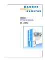
OP2000
OPERATOR MANUAL
Shuttle
OP2000 / C2000
BELLHEIMER METALLWERK GMBH
ID: 135 274.9
Revision 1.03 - February 2002
Version history
Revision
Description
Date of Introduction
1.00
Start version
August 1999
1.01
Revised version
September 1999
1.02
Revised version
April 2000
1.03
New functionalities (Appendix B-E)
February 2002
Copyright
(C) 1998, 1999 Bellheimer Metallwerk GmbH
All rights reserved worldwide.
This publication or part thereof may not be reproduced, stored in a retrieval system, transmitted, transcribed or
translated into any human or computer language, in any form or by any means, electronic, mechanical, magnetic,
optical, chemical, manual or otherwise, without the express written permission.
Disclaimer
Bellheimer Metallwerk GmbH makes no representations or warranties with respect to the contents hereof and
specifically disclaims any implied warranties of merchantability or fitness for any particular purpose.
Further, Bellheimer Metallwerk GmbH reserves the right to revise this publication and to make changes from time
to time in the contents hereof without obligation of Bellheimer Metallwerk GmbH to notify any person or
organisation of such revision or changes.
2
Operator Manual OP2000 / C2000 - SHUTTLE
V 1.03 – 02/2002
BELLHEIMER METALLWERK GMBH
Table of Contents
Table of Contents
1
Basic Functions - Shuttle............................................................................................ 5
1.1
1.2
1.3
2
Man – Machine – Interface (MMI)................................................................................ 7
2.1
2.2
2.3
2.4
2.5
3
Operator Panel of Control C2000 ........................................................................................................7
Adjustment of Brightness and Contrast of Screen...............................................................................8
Operator Panel Keyboard ....................................................................................................................8
Alphanumeric Character Input ...........................................................................................................10
Direct Language Switch-Over ............................................................................................................12
Power-On.................................................................................................................... 13
3.1
4
Operation / Display...............................................................................................................................5
Unit Functions ......................................................................................................................................5
User Surface ........................................................................................................................................5
Start-Up Routine ................................................................................................................................13
Operation.................................................................................................................... 15
4.1
Select main menu ..............................................................................................................................15
4.2
Manual Mode (Basic Operation) ........................................................................................................16
4.2.1
Operational Modes for Tray Unlatching ......................................................................................17
4.2.2
Positioning Screen ......................................................................................................................19
4.3
Storage Compression ........................................................................................................................22
4.4
Article Storage Location Administration "DB2000" ............................................................................23
4.5
Host Communication..........................................................................................................................24
4.5.1
Commission List Handling ..........................................................................................................25
4.5.2
EDP Call-Up (Storage / Retrieval of Parts).................................................................................27
4.5.2.1 Confirmation of Commission Storage / Retrieval to the Host .................................................28
4.6
Information System ............................................................................................................................29
4.6.1
Running Time Meter / Access Counter.......................................................................................30
4.6.2
E-Buffer Display ..........................................................................................................................31
4.6.3
Last Service ................................................................................................................................32
4.6.4
Display of Date and Time ...........................................................................................................33
4.6.5
Revision Display .........................................................................................................................34
5
6
System Messages...................................................................................................... 37
Service Mode ............................................................................................................. 41
6.1
Selection of System Language ..........................................................................................................43
6.2
Definition of Machine Parameters......................................................................................................44
6.2.1
Initialization and Update of Machine Parameters .......................................................................45
6.2.1.1 First Initialization......................................................................................................................46
6.2.1.2 Set up machine type ...............................................................................................................52
6.2.1.3 Learn Shelves .........................................................................................................................53
6.2.1.4 Learn trays ..............................................................................................................................56
6.2.1.5 Without function.......................................................................................................................57
6.2.1.6 Adjustment of Height Detection System .................................................................................57
6.2.2
Definition of Access Opening......................................................................................................58
6.2.3
Modify Shelf Table ......................................................................................................................59
6.2.3.1 Adding an entry into the shelf table.........................................................................................59
6.2.3.2 Deleting an entry from the shelf table .....................................................................................59
6.2.3.3 Display of shelf table – without modifications .........................................................................60
6.2.3.4 Verify shelf for position............................................................................................................61
6.2.4
Operation of the Connected Drive Control (Frequency Inverter)................................................63
6.2.5
Modify Tray Table .......................................................................................................................65
6.2.5.1 Addition of an entry to the tray table .......................................................................................67
6.2.5.2 Deletion of an entry from the tray table...................................................................................67
6.2.5.3 Deletion of tray table ...............................................................................................................68
6.2.5.4 Display of tray table – without modifications ...........................................................................69
6.2.5.5 Diagnostic Functions ...............................................................................................................70
6.2.5.6 Locking System .......................................................................................................................71
6.2.5.7 Tray extraction.........................................................................................................................72
6.2.5.8 Extractor ..................................................................................................................................73
V 1.03 – 02/2002
Operator Manual OP2000 / C2000 - SHUTTLE
3
Table of Contents
BELLHEIMER METALLWERK GMBH
6.2.5.9 Lift ........................................................................................................................................... 74
6.2.5.10 Safety shutter...................................................................................................................... 74
6.3
General Adjustments......................................................................................................................... 75
6.3.1
Unit Adjustments ........................................................................................................................ 76
6.3.2
E-Data Buffer ............................................................................................................................. 77
6.3.3
Host Adjustments ....................................................................................................................... 78
6.3.4
Set Date / Time .......................................................................................................................... 79
6.3.5
Interface Definition ..................................................................................................................... 80
6.3.5.1 Adjustments – Serial interface................................................................................................ 80
6.3.5.2 Adjustments – Ethernet-TCP/IP ............................................................................................. 82
6.3.6
Change Password...................................................................................................................... 84
6.3.7
Delete Database ........................................................................................................................ 86
6.3.8
Setup of Travel Speed ............................................................................................................... 87
6.4
Endurance Run ................................................................................................................................. 89
6.5
User Administration ........................................................................................................................... 91
6.6
Save Service Date............................................................................................................................. 91
A
B
C
D
E
F
4
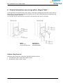
General Information concerning option „Hinged Table“...................................... A-1
M-buffer function...................................................................................................... B-1
Data Backup on PC-Flash-Card .............................................................................. C-1
User management for SHUTTLE NT ....................................................................... D-1
Weight Management ................................................................................................ E-1
DB2000 - Guideline .................................................................................................. F-1
Operator Manual OP2000 / C2000 - SHUTTLE
V 1.03 – 02/2002
BELLHEIMER METALLWERK GMBH
Basic Functions
1 Basic Functions - Shuttle
1.1
Operation / Display
¦
Input operation via an alphanumeric keyboard – output indication via
graphic liquid crystal display (LCD) with background illumination
¦ Output of system information in clear text and/or graphic symbols
¦ Option of system languages; 4 national languages are stored in the operator panel
¦ The basic user interface by determination of the storage location
·
Tray number
3-digit, numerical (1 - 999)
·
Position in the tray
3-digit, numerical (1 - 199)
·
Tray depth
2-digit, numerical (1 - 99)
¦
·
·
·
·
·
Multiple diagnostic functions by selection in the information module
Running time meter of machine power-on time
Running time meter of motor run time
Cycle counter, i.e. number of drive starts
System status indicator covering the complete basic sensory equipment
of the system – error evaluation
Firmware / hardware revision display
1.2 Unit Functions
¦ Due to an optimal integration of the unit and drive control unit, optimal system and travel performances
are achieved:
·
High degree of soft-start and soft-stop characteristics
·
Quiet and smooth running characteristics
·
Exact positioning of the tray
·
Height-optimized or fixed shelf allocation
·
Vertical and horizontal speed are adjustable for each tray
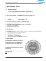
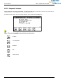
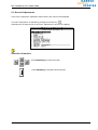
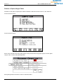
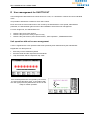
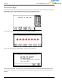
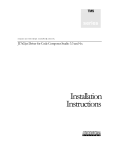
1.3 User Surface
Communication with the unit occurs via the operator
panel (OP2000) of the control C2000.
INFORMATION
SYSTEM
The user interface is composed of 5 main menus, which
can be separated into operation menus, and service and
information menus.
V 1.03 – 02/2002
G
EM
EN
T
This enables even inexperienced users to efficiently
operate the units.
The dialog with the unit occurs by clearly arranged
screens and the keyboard of the operator panel.
T
TS
PAR
The user is led through menus adapted to each
application, which are again divided into submenus.
MUNIC
AT
COM
T
IO
S
N
HO
IC MOD
S
E
BA
SERVICE
MODE
O
RA
NA
GE
A
LOCATION M
Operator Manual OP2000 / C2000 - SHUTTLE
5
Basic Functions
BELLHEIMER METALLWERK GMBH
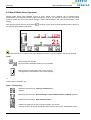
Operation Menus
Basic Operation
Within this menu it is possible to directly select a storage location by entering the respective
tray number.
In addition, there is the possibility of manually selecting storage locations (trays) by pushing
the UP/DOWN-arrow-keys.
Part Storage Location Management DB2000 (Option)
This menu is available as an option. It comprises the administration of parts and storage
locations. By input of the parts number, it is possible to position the pertinent storage
location (tray) in the respective access opening. The display of the position on the trays is
included.
Host Communication
In this menu, the management of the system controlled by a host computer system (PCstorage administration).
Parallel to the operation via PC, the machine-operator panel can be used (emulation hostconsole), e.g.:
· Selection of part number
· Selection of order number
· Quantity confirmations, etc.
Service and Information Menus
Service Mode
In this mode, it is possible to adjust connected peripheral units, manage access
authorization, operate all motor-driven parts individually, control storage administration.
Information System
The information system offers an overview over important data concerning the configuration
and the utilization of control and machine.
These main menus branch into submenus.
6
Operator Manual OP2000 / C2000 - SHUTTLE
V 1.03 – 02/2002
BELLHEIMER METALLWERK GMBH
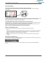
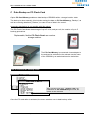
Man – Machine – Interface (MMI)
2 Man – Machine – Interface (MMI)
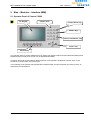
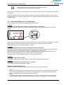
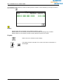
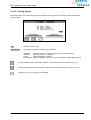
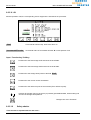
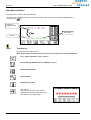
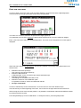
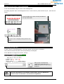
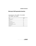
2.1 Operator Panel of Control C2000
LC- Display
numeric keys
escape (abort)- key
delete - key
return (confirmation) -Key
cursor- Key
function-key
The operator panel of control C2000 has an LC-display with graphic features and an illuminated background.
Brightness and contrast of the screen can be adjusted individually.
All entries are made via the operator panel keyboard. This keyboard is divided into numeric keys, cursor
control keys, function keys and control keys..
The foil design of the operator panel guarantees industrial water and dust protection according to IP54, as
appropriate for industrial use.
V 1.03 – 02/2002
Operator Manual OP2000 / C2000 - SHUTTLE
7
Man – Machine – Interface (MMI)
BELLHEIMER METALLWERK GMBH
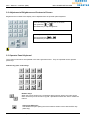
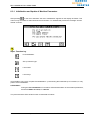
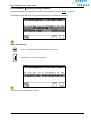
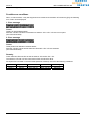
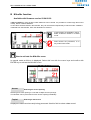
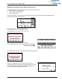
2.2 Adjustment of Brightness and Contrast of Screen
Brightness and contrast of the display can be adjusted from the operator panel keyboard.
Press and hold the „ESC“ key min. 2 seconds,
or
then press key
simultaneously to adjust brightness
Press key and hold „ESC“ min. 2 seconds,
after that press key
or
simultaneously to adjust contrast
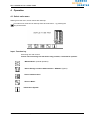
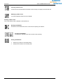
2.3 Operator Panel Keyboard
The screens of all menus are operated in the same general manner: They are operated via the operator
panel keys.
Numeric key pad / control keys
Numeric keys:
When the screen shown on the LC-display allows numeric entries, the input can be
done via the keys of the numeric key pad. Alphabetical entries are done in a different
manner.
Cancel key (ESC-key):
Cancellation of input / quitting the screen without entries is done with the ESC-key.
(Abort key)
8
Operator Manual OP2000 / C2000 - SHUTTLE
V 1.03 – 02/2002
BELLHEIMER METALLWERK GMBH
Man – Machine – Interface (MMI)
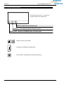
Delete key:
By pressing this key, the character to the left of the cursor in the input field is
deleted.
Enter key:
Confirmation and completion of performed entries is always done with the ENTERkey.
Cursor control keys
The cursor control keys serve to jump from one field to another within the screen. They are also used to
move the selection in a select screen.
left
right
up
down
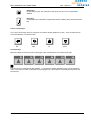
Function keys
Below the display 6 function keys are arranged, which are labeled F1 to F6 from left to right.
Function keys are controlled by the software, i.e. the function softkey depends on the current operation
menu. The current function is identified by a pictograph in the lower part of the display directly above the
function key.
V 1.03 – 02/2002
Operator Manual OP2000 / C2000 - SHUTTLE
9
Man – Machine – Interface (MMI)
BELLHEIMER METALLWERK GMBH
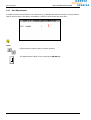
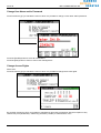
2.4 Alphanumeric Character Input
The input of alphanumeric characters can be done via the function keys. Thus, the operator panel offers the
possibility to input letters and special characters without the addition of an alphanumeric keypad.
(Note: For special applications an alphanumeric standard keyboard can be connected to the control C2000.)
Selection of alphanumeric input:
Whenever this pictograph is shown with this graphic symbol, entry of letters and
special characters into the provided fields on the screen is possible.
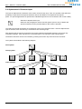
The letters and special characters are combined in groups of six characters each. After the alphanumeric
input is selection, each function key is reserved for one of these groups.
After pressing the function key reserved for the group containing the desired character, the function key
reservation changes. Each function key is now reserved for one character of the selected group.
The desired character can then be inserted by pressing the function key reserved for this character.
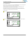
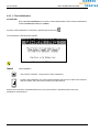
This system is described in the following diagram.
Start symbol
Group symbol
Letter symbols
10
Operator Manual OP2000 / C2000 - SHUTTLE
V 1.03 – 02/2002
BELLHEIMER METALLWERK GMBH
Man – Machine – Interface (MMI)
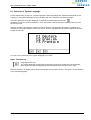
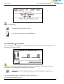
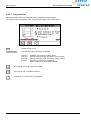
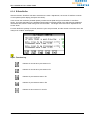
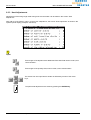
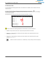
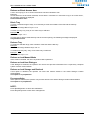
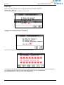
The procedure of inserting a letter or special character and the accompanying change of symbols is shown
by means of an example in host communication:
Select „Alphanumeric Input“
Select a „group“ of characters
S
T
U
V
W
X
Pressing softkey: Input of the required character
V 1.03 – 02/2002
Operator Manual OP2000 / C2000 - SHUTTLE
11
Man – Machine – Interface (MMI)
BELLHEIMER METALLWERK GMBH
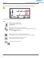
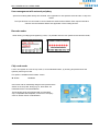
2.5 Direct Language Switch-Over
Control C2000 offers the possibility to display the operator menus in different languages. Select the required
l language via by pressing function keys F1 and F2.
Key combination
+
Press F1-key and hold.
Press F2-Taste too.
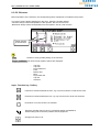
The display switches to the language selection screen. This is where the language can be changed. After
the language has been selected, the current screen is displayed in the chosen language. E.g., if English
was selected starting from the above screen, the following screen appears in the display:
12
Operator Manual OP2000 / C2000 - SHUTTLE
V 1.03 – 02/2002
BELLHEIMER METALLWERK GMBH
Power-On
3 Power-On
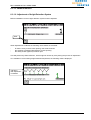
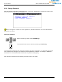
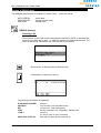
3.1 Start-Up Routine
After “Power-On” the control checks several system operating conditions, e.g. stored parameters, error
conditions, connected peripherals, sensory equipment, safety functions, etc.
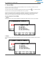
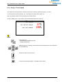
During this start-up routine, the “start-up screen” shown below is displayed on the operator panel. As long
as the start-up screen is displayed, inputs are not possible.
After conclusion of the start-up routine, two different cases are possible.
Ø
Ø
The first initialization has already been performed once. The display changes to the basic “Menu
Selection Screen”. If a screen of the operation menus, basic operation (manual mode) or host
communication was displayed before the last power-off, the display changes directly to that screen. If a
screen from the menu “Article Storage Location Administration – DB2000 was active, it is switched over
to the “DB2000 Log-On Screen”.
The machine is now ready for operation.
The machine was turned on for the first time after installation.
The control recognizes this and immediately branches off into the menu "First Initialization".
A trained service technican is required for this function.
V 1.03 – 02/2002
Operator Manual OP2000 / C2000 - SHUTTLE
13
BELLHEIMER METALLWERK GMBH
Operation
4 Operation
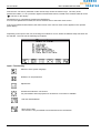
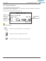
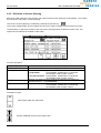
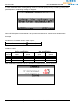
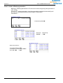
4.1 Select main menu
Starting from this menu, 5 main menus are called up.
The main menu mask can be called up from each sub-menu - by pressing the
-key several times.
Input: Function key
Branching into main menus.
Please note: branching into sub-menus only possible, if released for operator.
“Manual Mode” (manual operation)
"Article Storage Location Administration – DB2000" (Option).
"Host Communication"
"Service Mode"
"Information System".
V 1.03 – 02/2002
Operator Manual OP2000 / C2000 - SHUTTLE
15
Operation
BELLHEIMER METALLWERK GMBH
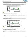
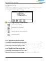
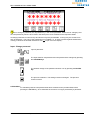
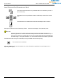
4.2 Manual Mode (Basic Operation)
Manual mode allows user-controlled access to trays. Travel of the machine can be initiated semiautomatically by entering the number of the required tray. Further, it is possible to branch from the manual
operation mode into the menus “Article Storage Location Administration” and "Host Communication / Host
Dialog".
After pressing the function key reserved for
the operator panel display (see below).
, the basic screen of the manual operating mode is shown in
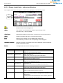
In the field "Current" the number of the tray is displayed, which is currently located in the access opening.
Input:
Input of target tray number
Input of position and depth position in tray (optional).
Start of target tray transport to the access opening.
The target tray is transported to the access opening.
or
Confirmation of a function key:
Input: Function key
Branching into the menu " Storage Compression "
(Option).
Branching into the menu "Article Storage Location Administration -DB2000" (Option)
Branching into the menu „Host Communication“
Deletion of entries for the tray currently located in the access.
The tray number, as well as all relevant data related to this tray are deleted after inquiry.
16
Operator Manual OP2000 / C2000 - SHUTTLE
V 1.03 – 02/2002
BELLHEIMER METALLWERK GMBH
Operation
Unlocking of the tray currently located in the access opening4x
The tray may then be removed from the machine.
While the unit is in operation, the positioning screen is shown in the operator panel. During this time, input is
not possible.
When the machine stops, the basic screen of the manual operation mode appears again. In field "Current",
the number of the tray currently located in the access opening is displayed. Data input into the tray input field
is possible again.
4.2.1 Operational Modes for Tray Unlatching
Press function key [F6] to enable the following operational modes:
1. Option:
Table option 'hinged table' has not been released OR table is folded down.
By activating function key [F6], it is possible to manually release a tray which is currently in the access
opening.
If this tray is completely removed from the access opening, the current tray number is deleted from both tray
table and display. The tray is therefore retrieved and has become invalid for the control system.
When restoring this tray, the number must be re-entered.
2. Option:
Table option Hinged Table has been released and the table is folded up.
Immediately after the machine operator has ordered a tray into the access opening via the manual, host or
data base menu, the current status of the table is evaluated by the control system.
If the table is properly locked, the tray is unlatched automatically and is ready to be transferred on to the
table. The number assigned to this tray remains valid for the control system.
Should one of the errors listed below appear, the tray will remain locked
3. Option:
Table option Tray lock is released
A tray sitting in the access opening is locked. Press function key [F6] to release the tray.
4. Option:
Table option Automatic Full Tray Extraction is released
Tray release is activated as described in Option 1.
Options for unlatching a tray
In order to transfer a tray on to the table, the tray must have been previously unlocked
1. Option:
A tray, which has been previously transferred into the access opening, is automatically unlocked via the
manual, host or data base menu if the table is completely folded up, correctly latched and the table
option in the display unit of the software has been released.
2. Option
In manual mode a tray sitting in the access opening is unlatched manually, when function key [F6] is
activated. Same applies to the released table options Tray Lock and Automatic Full Tray Extraction.
V 1.03 – 02/2002
Operator Manual OP2000 / C2000 - SHUTTLE
17
Operation
BELLHEIMER METALLWERK GMBH
Restoring an unlatched tray
A tray can only be restored if it is positioned completely in the access opening. If the tray (or part thereof) is
still on the table, the following message appears:
After a tray has been transported into the access opening, it will be restored and correctly positioned when
the [ENTER]-key is pressed.
18
Operator Manual OP2000 / C2000 - SHUTTLE
V 1.03 – 02/2002
BELLHEIMER METALLWERK GMBH
Operation
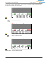
4.2.2 Positioning Screen
During each travel, i.e. every time a tray is moved, the "Positioning Screen" is shown in the operator panel
display. As long as the positioning screen is displayed, no input is possible.
Information about height of the actual tray is shown in the lower part of the positioning screen, where
otherwise the pictograms of the function key reservation are displayed.
When operating the machine within the menus „Host Communication“ and „Article Storage Location
Administration“ the positioning screen contains additional information about storage location and article.
Following the process of retrieving a tray into the access is described:
„Retrieve Tray“
As soon as the tray has been pulled onto the extractor, the current tray number and height are displayed.
V 1.03 – 02/2002
Operator Manual OP2000 / C2000 - SHUTTLE
19
Operation
BELLHEIMER METALLWERK GMBH
If the tray has been positioned into the workstation without error, the following screen is displayed.
Once finished with the tray, the operator has the following options:
Input:
Without entering a new tray number ;
The current tray is returned to storage.
è „Store Tray“
When entering a new tray number in "Tray Input Field"
The current tray is returned to storage, and the next tray is retrieved to the access
opening.
è „Store tray è Retrieve tray”
Deleting of entries of the tray currently located in the access.
The tray number as well as all relevant data pertaining to this tray are deleted.
Unlocking of the tray currently located in the access.
The tray may then be removed from the unit.
Branching into the various menus.
20
Operator Manual OP2000 / C2000 - SHUTTLE
V 1.03 – 02/2002
BELLHEIMER METALLWERK GMBH
Operation
„Store Tray”
When the storage process of the current tray is consistent, and if no new tray is requested, the basic screen
is displayed again.
The subsequent procedure is described on page 16.
When the storage process of the current tray is concluded, and if a new tray has been requested, the
process is continued with the function „Retrieve Tray”, see example tray no. 5.
Subsequent procedure see „Retrieve tray“
V 1.03 – 02/2002
Operator Manual OP2000 / C2000 - SHUTTLE
21
Operation
BELLHEIMER METALLWERK GMBH
4.3 Storage Compression
Caused by the optimized storage method single storage locations with a small height could result with raising
useful life of the machine which cannot be avoided through technical reasons. This could lead to the fact that
a storage item could not be stored though there is enough free storage location.
To make this free space usable again, we have the “storage compression” function.
The “storage compression” creates the possible max. connected free space of the machine. Therefore, the
trays from the upper area of the machine will be restored to the bottom.
ATTENTION! Only the trays with the option “optimised” will be restored, the “fixed allocation trays”
will resist on the assigned storage shelf!
Abort the function with ESC.
It may take some time until the process will be aborted after pressing the ESC key. The reason is that the
last action “tray” on “storage shelf” will first be finished.
After aborting the function it can be continued starting from the condition in which the trays are stored at that
time.
Warning! The storage compression process may take some time depending on the unit height and
the degree of the “storage location splitting”.
22
Operator Manual OP2000 / C2000 - SHUTTLE
V 1.03 – 02/2002
BELLHEIMER METALLWERK GMBH
Operation
4.4 Article Storage Location Administration "DB2000"
As an option, there is an Article Storage Location Administration available, which is directly integrated into
the control.
The main functions of this system are:
·
·
·
·
·
·
Article storage location administration
Empty location administration
Administration of stock
Minimum stock check
FIFO (First-In-First-Out)
Reports on display / printer
To call up the menu "Article Storage Location Administration" press the designated function key with the
pictograph
.
The menu article storage location administration is described in a separate user manual (ID:35694.9).
V 1.03 – 02/2002
Operator Manual OP2000 / C2000 - SHUTTLE
23
Operation
BELLHEIMER METALLWERK GMBH
4.5 Host Communication
The control has the possibility for down- and up-loading messages and commands from/to a connected
computer system, e.g. status messages, but also inputs done at the operator panel. The complete dialog –
protocols, telegrams – is described in a separate manual "Host Dialog" (Id.-No. 35 816.8).
The interfaces through which the systems (control and computer) are communicating, is set in the menu
"Service Mode".
ATTENTION !
Communication between control and host is only possible, if the menu „Host
Communication“ on the operator panel is active.
The menu “Host Communication" enables the simulation of the host system’s workstation (e.g. PC monitor /
keyboard) by the operator panel. The essential functions, which can be performed from the menu, are:
Ø
Ø
Processing of order lists, which are loaded into the control by the host (E1-, E2-handling), with
acknowledge message to the host
Store / retrieve parts to / from stock by communicating with the host (EDP call-up; F2 handling
The menu "Host communication" is called up by pressing the function key reserved by
Subsequently, the basic screen of the menu “Host communication” appears in the operator panel display.
manual
operation
24
order
list
EDP
buffer
Operator Manual OP2000 / C2000 - SHUTTLE
V 1.03 – 02/2002
BELLHEIMER METALLWERK GMBH
Operation
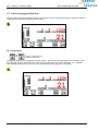
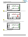
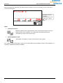
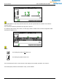
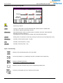
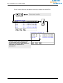
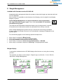
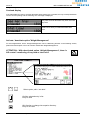
4.5.1 Commission List Handling
Pending transactions in the buffers E1 / E2 are signaled by flashing softkeys E1 / E2.
E1 / E2
flashing
Input: Function key / Softkey
Selection of a data record from the E1 or E2 list buffer.
Subsequently, a data record from the selected buffer is processed. The pictograph of the selected function
is shown inversely during that time.
The tray containing the article indicated in the data record is retrieved into the access opening.
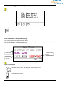
While the unit is moving, the positioning screen is shown in the operator panel display (below). In the menu
"Host Communication“ the current article number, the precise article storage location (tray, position in the
tray, as well as depth position in the tray) and the quantity transaction.
Depth position
Target tray
Tray currently
located in the
access opening
Tray height
V 1.03 – 02/2002
Operator Manual OP2000 / C2000 - SHUTTLE
25
Operation
BELLHEIMER METALLWERK GMBH
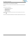
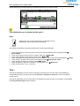
When the target tray is delivered, the data record information is shown on the basic screen of the menu
"Host Communication".
Pictograph is shown
inversely:
record from the E1- list
buffer is pro- cessed
Input:
·
Quantity Correction:
Before the data record is reported back to the connected host system, the input /
output quantity can be adjusted. For adjustment, the displayed quantity is
overwritten by means of the numeric keys.
·
Handling Report to Host:
Confirmation of handling, in order to send report to host system.
The „Softkey“ looks normal again, if there are no further data records available in the E1 / E2 list buffers. If it
is flashing, additional records are available.
26
Operator Manual OP2000 / C2000 - SHUTTLE
V 1.03 – 02/2002
BELLHEIMER METALLWERK GMBH
Operation
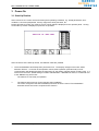
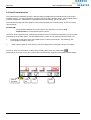
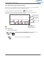
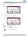
4.5.2 EDP Call-Up (Storage / Retrieval of Parts)
With this function an optional alphanumeric information will be sent to the host, e.g. an article number for
storage / retrieval. Special software on the PC is required for this function.
The menu "EDP Call-Up" is selected by pressing the
designated function key.
Subsequently, the screen for the menu "EDP Call-Up" is displayed. In order to promt that input of
information is expected, the information field is shown inversely.
Information field
Quantity field
Input "#"
Alphanumeric
character input
Input: EDP-Call-Up
·
Input of Article Information:
Input of any text into the Information field (e.g. article number, order
number), depends on the functionality of the host system.
Input of transaction quantity into quantity field.
V 1.03 – 02/2002
Operator Manual OP2000 / C2000 - SHUTTLE
27
Operation
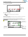
·
BELLHEIMER METALLWERK GMBH
Confirmation of Input and Report to Host:
Confirmation without reference to input of storage or retrieval.
Confirmation of quantity for storage of parts to stock.
Confirmation of quantity for retrieval of parts from stock.
Inputs are locked as long as data transfer to the host is active. This status is announced to the user by the
following screen (example) in the operator panel display.
Abortion of program execution possible by pressing
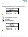
4.5.2.1 Confirmation of Commission Storage / Retrieval to the Host
By EDP call-up the communication with an article storage location administration program (e.g. a program of
the PowerPick-family) can be produced. For the handling of data records to be commissioned, which had
been made available by such a program, the control C2000 offers a facilitation of work by the function key
reserved for
After the call-up of a commission by the article storage location administration program in the menu "EDP
call-up", the data records of the called-up commission are displayed one after the other in the basic screen of
the menu "Host communication". Each displayed commissioning data record must first be reported to the
article storage location administration program, before the next data record of the commission is displayed.
By means of the function key reserved by
a data record (without quantity correction) can
be confirmed directly on the basic screen of the menu “host communication”.
28
Operator Manual OP2000 / C2000 - SHUTTLE
V 1.03 – 02/2002
BELLHEIMER METALLWERK GMBH
Operation
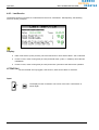
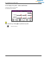
4.6 Information System
The menu "Information" offers the possibility of displaying important data concerning the configuration and
the utilization of control and machine. Inputs in the sense of messages to the system are not possible within
the menu "Information".
The menu "Information" is selected by pressing the function key.
Subsequently, in the basic screen of the menu "Information" various functions are offered to choose from.
Selection of function:
Select a function by means of the CURSOR-keys.
The selected function item is started by pressing the ENTER-key.
V 1.03 – 02/2002
Operator Manual OP2000 / C2000 - SHUTTLE
29
Operation
BELLHEIMER METALLWERK GMBH
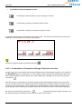
4.6.1 Running Time Meter / Access Counter
The display function "Running time" is selected from the menu "Information". Subsequently, the following
screen is shown (example):
Display of:
Total Power-on Time – Operating time of machine, accumulated from the time of last initial
start-up. During an initial start-up the value is reset.
This Power-on Time– Operating time of machine since the last power-on.
Total Cycle time – of machine, accumulated from the time of last initial start-up. During an
initial start-up the value is reset.
Total cycles Count – frequency of drive starts, accumulated from the time of last initial startup. During an initial start-up, the value is reset.
Input:
or
30
The display function is aborted. The screen of the menu "Information" is
shown again.
Operator Manual OP2000 / C2000 - SHUTTLE
V 1.03 – 02/2002
BELLHEIMER METALLWERK GMBH
Operation
4.6.2 E-Buffer Display
The display function "E-buffers" is called up from the menu "Information". Subsequently, the following
screen is shown (example):
Display:
The contents of both host buffers E1 and E2 are displayed. Separated into data records, which
have to be processed yet, and data records ready to be called back.
Input:
or
V 1.03 – 02/2002
The display function is aborted. The screen of the menu "Information" is
shown again.
Operator Manual OP2000 / C2000 - SHUTTLE
31
Operation
BELLHEIMER METALLWERK GMBH
4.6.3 Last Service
The display function "Last service" is selected from the menu "Information". Subsequently, the following
screen is shown (example):
Display:
●
Date of last service (more precisely, since the last function "Save Service Date" was conducted.
●
Power-on time, motor running time (in hours) and total motor cycles, i.e. added up since the last
initialization.
●
Power-on time, motor running time (in hours) and motor cycles since the last service operation.
ATTENTION !
The service data are only logged, if the function „Save Service Date“ is selected!
Input:
or
32
The display function is aborted. The screen of the menu "Information" is
shown again.
Operator Manual OP2000 / C2000 - SHUTTLE
V 1.03 – 02/2002
BELLHEIMER METALLWERK GMBH
Operation
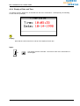
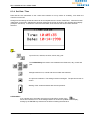
4.6.4 Display of Date and Time
The display function "Date/Time" is selected from the menu "Information". Subsequently, the following
screen is shown (example):
Display:
Date and time at the moment of call-up of the display function item.
Input:
or
V 1.03 – 02/2002
The display function is aborted. The screen of the menu "Information" is
shown again.
Operator Manual OP2000 / C2000 - SHUTTLE
33
Operation
BELLHEIMER METALLWERK GMBH
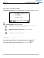
4.6.5 Revision Display
By using the function "Version" the software and hardware revision status of control C2000 can be displayed.
The display function "Version" is called up from the menu "Information". Subsequently, the screen "Software
Version" is shown (example):
Display:
The revision status of the following software modules is displayed:
CPU-Software:Control software incl. the operating system
DB2000:
Optional Article Storage Location Administration software
OP-BIOS:
Basic input output system of operation panel
OP-TOS:
Operating system of the operation panel
-Software: up-to-date application software of the operation panel
Input:
Switch-over to hardware version display
or
34
The display function is aborted. The screen of the menu "Information" is
shown again.
Operator Manual OP2000 / C2000 - SHUTTLE
V 1.03 – 02/2002
BELLHEIMER METALLWERK GMBH
Operation
The hardware version display is called up starting with the software version display by pressing the function
key reserved by
Display:
Serial number and check date of the installed hardware module.
Modul GS200-xx is the identity number for the CPU (Central Processing Unit) of C2000.
Modul GS202-xx is the identity number for MIF1 (Machine interface) of C2000.
Eingabe:
Switch-over to the software version display.
or
V 1.03 – 02/2002
The display function is aborted. The screen of the menu "Information" is
shown again.
Operator Manual OP2000 / C2000 - SHUTTLE
35
BELLHEIMER METALLWERK GMBH
System Messages
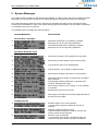
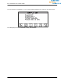
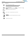
5 System Messages
The system shows messages on the operator panel display, in order to inform the user of activities currently
taking place or having been completed, error states having been determined and breaches of defaults.
Error states threatening safety are shown until they are remedied and until the error message has been
confirmed by the ENTER-key. Other, less critical warning signs and messages, are only shown momentarily.
A confirmation of entry is not required.
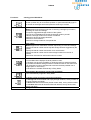
The possible system messages are listed as follows:
SYSTEM MESSAGE:
EXPLANATION:
General Error messages
m
Ø
Stored tray information is completely or partially
destroyed. Unit is no longer fully operational.
m
Ø
Stored shelf positions are completely or partially
destroyed. Unit is no longer fully operational..
m
Ø
Entered tray number is not available in the tray table.
m
Ø
Entered tray number already exists in the tray table
m
Ø
Tray denied to user in user administration.
m
Ø
During retrieval , tray is sitting on folded up table.
m
Ø
Entered access opening unknown to control system.
m
Ø
Admissible maximum height of storage items exceeded
during retrieval.
m
Ø
During height-optimized restorage, no storage place
found for storage goods height
m
Ø
Entered shelf number is out of range, ie. is not available
in tray table.
m
Ø
Entered shelf found, but not vacant.
m
Ø
Real height of storage goods exceeds height allocated to
this tray in the tray table.
m
Ø
m
Ø
m
Ø
Extractor fingers not in correct position.
> Check sensory system in diagnostic function of
extractor.
Extractor positioning takes too long
>load parameter list frequency inverter, check motor,
sensory system and mechanism.
Extractor motor overheated.
> load possibly overcharged. Temporarily switch off
controls to cool down motor and check mechanism .
Operation-/Software- Error
messages
Hardware Errors
V 1.03 – 02/2002
Operator Manual OP2000 / C2000 - SHUTTLE
37
System Messages
BELLHEIMER METALLWERK GMBH
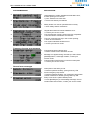
SYSTEM MESSAGE:
EXPLANATION:
m
Ø
m
Ø
m
Ø
m
Ø
m
Ø
m
Ø
m
Ø
m
Ø
m
Ø
m
Ø
m
Ø
m
Ø
m
Ø
m
Ø
m
Ø
m
Ø
m
Ø
Function aborted by control system.
m
Ø
Height detection system indicates hardware error.
> contact service centre.
38
Problems when positioning lift system
> check motor and sensory system.
Move lift to reference point in diagnostice function
Lift has reached upper limit stop.
> Check tray table, check switch S3 on extractor , if
required, move lift to reference point in diagnostice
function
Lift has reached lower limit stop
> Check tray table, check switch S4 on extractor , if
required, move lift to reference point in diagnostice
function.
Lift motor speed excessively high.
> If this appears repeatedly, enter menu Service, Unit,
Frequency inverter and press [F1]-key for access to
frequency inverter parameter list
Lift motor speed excessively low.
> If this appears repeatedly, enter menu Service, Unit,
Frequency inverter and press [F1]-key for access to
frequency inverter parameter list
lift motor overheated.
> load possibly overcharged. Temporarily switch off
controls to cool down motor and check mechanism .
Tray sitting in the access opening.
> Remove tray and check switch 1S5 and sensory
system in access opening.
Tray sitting in the access opening.
> Remove tray and check switches 1S5, 1B3 (IN21) ad
1B4 (IN20) in the respective access opening.
Tray position in access opening not correct.
> Adjust tray until message stops appearing.
Unsecured tray on extractor.
>Check extractor finger position in diagnostic function of
lift.
Extractor sensors indicate incorrect tray position.
> check proximity switches B4 (IN13) and B7 (IN14)
Tray to be retrieved is not found in shelf
> Check entry into tray table. Tray is either removed or
stored in a different shelf.
Hinged table not fully locked.
> check mechanism and table switches (table top = IN24,
table bottom = IN25),
Tray extractor finger are neither in front not in rear stop
position.
> Move extractor fingers in one of the stop positions in
diagnostic function mode.
Tray lock could not release tray from access opening.
> check lock mechanism
Front door access opening not correctly open or closed.
> check switch 1S6.
Operator Manual OP2000 / C2000 - SHUTTLE
V 1.03 – 02/2002
BELLHEIMER METALLWERK GMBH
System Messages
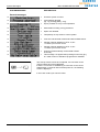
SYSTEM MESSAGE:
EXPLANATION:
m
Ø
m
Ø
m
Ø
Safety shutter can not be opened/closed correctly.
> check safety shutter mechanism
m
Ø
Hinged table switches indicate hardware error.
> Contact your service centre.
m
Ø
Tray full extraction (in/out) could not be fully completed.
> Check extractor mechanism and sensors.
m
Ø
Tray lock could not lock tray in the access opening.
> check lock mechanism.
m
Ø
Lock system indicates hardware error.
> contact your service centre.
m
Ø
Connected inverter indicates error .
> Return to basic menu and switch off unit.
m
Ø
m
Ø
Message can appear during unit start-up routine.Press
[ENTER]-button, if message remains, contact your
service centre.
Communication with frequency inverter is interrupted.
> Contact your service centre.
Height detection system indicates that hardware error,
access opening is not vacant>
> poss. obstacle in access area.
> Check lock and tray mechanism
Frequency inverter error message
General error messages
m
Ø
Interruption of the safety circuit.
> Restore operational safety, press green key 1S8
m
Ø
m
Ø
Press emergency-stop switch.
> Restore operational safety, turn emergency-stop switch
counter-clockwise to release; press green key 1S8.
Relay in exit OUT11 (MIF1/GS202) stuck.
> Press [ENTER]-key to acknowledge message. If error
remains after switch off/on, contaict your service centre.
V 1.03 – 02/2002
Operator Manual OP2000 / C2000 - SHUTTLE
39
System Messages
BELLHEIMER METALLWERK GMBH
SYSTEM MESSAGE:
EXPLANATION:
General messages
m
Ø
Unit drive system is active.
m
Ø
m
Ø
Last operation aborted
(eg.. by pressing [ESC] – key).
inquiry, whether to carry out an operationl.
m
Ø
Authorization missing, wrong password.
m
Ø
Option not released.
m
Ø
Temporarily no tray stored in control system.
m
Ø
Incorrect code entered.ie automatic shift into Basic Menu.
m
Ø
Voltage in lithium batteries in CPU : 2,75V
> Contact your service centre.
m
Ø
Voltage in lithium batteries in CPU : 2,75V
> Contact your service centre.
m
Ø
Control unit automatically corrects data entered
incorrectly.
m
Ø
This message can appear after pressing function key [F1]
in a mask, when no assistance programme is available.
The start-up routine cannot be completed, if a connection to the
control C2000 cannot be established.
If there is no success in establishing a connection to the control
C2000 within 10 seconds after machine power-on, the following
screen is displayed.
In this case contact your service center.
40
Operator Manual OP2000 / C2000 - SHUTTLE
V 1.03 – 02/2002
BELLHEIMER METALLWERK GMBH
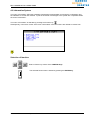
Service Mode
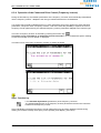
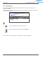
6 Service Mode
The menu "Service Mode" consists of all input possibilities, which are necessary to initialize a unit, the
interfaces and the overall functionalities.
The menu "Service mode" is activated by pressing the function key reserved by
. or, in case user names
have been stored, by entering Password 752 into the User Log In Menu:
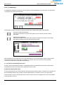
Access to menu "Service mode" is protected by a password. At the factory, the password "752" is predefined. This password can be changed in the sub-function „Adjustment“. After the menu has been
selected, the user is asked to enter a password via the screen on the display shown below.
Access options for Service Mode
1. Option:
Entering Customer Service Password 752 from the Main Menu Mask enables access to Service Mode.
2. Option:
Entering Customer Service Password 752 from the User Log In Menu enables immediate access to Service
Mode
V 1.03 – 02/2002
Operator Manual OP2000 / C2000 - SHUTTLE
41
Service Mode
BELLHEIMER METALLWERK GMBH
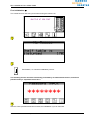
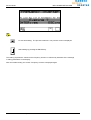
Now the user can enter a password via the numeric keys and/or the function keys. The entry of the
password is hidden, i.e. as a protection against unauthorized viewers, instead of the entered character a star
( ) is shown on the display.
*
Password entry is completed by pressing the ENTER-key.
If an incorrect password is entered, the screen switches over to the basic mode screen.
If the correct password was entered, the basic screen of the “service mode” menu appears in the operator
panel display.
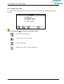
Depending on the input of the user, branching into submenus occurs, where the different setup functions can
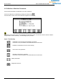
be selected. The user has the following input options.
Input: Function key
Selection of the system language
Definition of unit parameters
Adjustments
Activate the endurance run function
For presentation and test purposes an endurance run function is available.
Call User Administration.
Store service date
This function is only accessible to an authorized service technician!!
42
Operator Manual OP2000 / C2000 - SHUTTLE
V 1.03 – 02/2002
BELLHEIMER METALLWERK GMBH
Service Mode
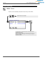
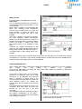
6.1 Selection of System Language
Control C2000 offers a choice of 4 system languages. Which languages are implemented depends on the
equipment. The system language can be selected in the menu “Selection of system language.”
The menu "Selection of system language" is called up by pressing the function key.
In addition, this menu can be selected from every user screen, without having to explicitly switch over into
the service mode
After the selection, the language selection screen is shown in the operator panel display. Following is an
example of a language selection screen of a control, which is equipped with the system languages German,
English and French.
The user can now determine the system language by his input.
Input: Function key
Language switch-over:
The system language is selected by pressing the function key assigned to the pictograph,
which depicts the desired language by the international motor vehicle country code.
After the selection, the display jumps back automatically to the previous screen. The letter is now presented
in the selected language.
V 1.03 – 02/2002
Operator Manual OP2000 / C2000 - SHUTTLE
43
Service Mode
BELLHEIMER METALLWERK GMBH
6.2 Definition of Machine Parameters
The machine parameters are defined in the menu "Machine".
The menu "Machine" is selected by pressing the function key
.
Then the basic screen of the menu "Machine" appears in the display.
Depending on the input of the user, branching into submenus occurs, in which the various machine-related
setup functions can be called up. The following input is possible:
Input: Function key
Initialization of the machine and updating of machine.
This menu is only accessible to an authorized service technician!
Definition of parameters for an access opening.
Add / remove tray positions.
Operation of frequency converter.
This menu is only accessible to an authorized service technician!
Modify shelf table.
Diagnostic functions
44
Operator Manual OP2000 / C2000 - SHUTTLE
V 1.03 – 02/2002
BELLHEIMER METALLWERK GMBH
Service Mode
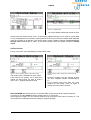
6.2.1 Initialization and Update of Machine Parameters
After pressing
in the menu "Machine" the menu "Initialization" appears on the display as follows. This
menu is only accessible to authorized service technicians! To unauthorized persons the message "Access
denied" is shown.
Input: Function key
First initialization.
Set up machine type.
Learn shelf.
Learn trays.
It is possible to carry out a complete first initialization – just as during the initial start-up of a machine, or only
parts of a first initialization.
ATTENTION !
During the first initialization of a machine, before determination of the machine parameters,
all internal tables are reset, i.e. cleared!
The process and the effect of this function is described as follows.
V 1.03 – 02/2002
Operator Manual OP2000 / C2000 - SHUTTLE
45
Service Mode
BELLHEIMER METALLWERK GMBH
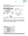
6.2.1.1 First Initialization
ATTENTION !
During the first initialization of a machine, before determination of the machine parameters,
all internal tables are reset, i.e. cleared!
Function "First Initialization" is selected by pressing the function key
.
On the display the following alert appears:
Input:
First Initialization
The process is aborted. The previous screen is displayed.
Continue the initialization, the control resets all tables and forces a re-start of the machine!
After the restart, same procedure as during an initial start-up.
If this process has been completed without error, then the machine is operable and the rest of the
parameters can be defined.
46
Operator Manual OP2000 / C2000 - SHUTTLE
V 1.03 – 02/2002
BELLHEIMER METALLWERK GMBH
Service Mode
First Initialization è
The control forces a new start, just as when turning the machine on.
Confirmation, i.e. introduce initialization process.
The following actions should be exclusively performed by an authorized technician, therefore a
password entry is requested at this time !
After the correct password has been entered, the initialization cycle is continued.
V 1.03 – 02/2002
Operator Manual OP2000 / C2000 - SHUTTLE
47
Service Mode
BELLHEIMER METALLWERK GMBH
First Initialization è Selection of System Language
Input: Function key
Language selection
After language selection, the screen display automatically reverts to the previous screen.
First Initialization è Set up Machine Type
The corresponding machine type must be defined.
Only when the type has been correctly set up, a perfect functioning of the machine is guaranteed, especially
with regard to the drive / running characteristics.
The various machine types are listed in a selection list.
Define table
Manual data
input
Defin
tray type
Input: Function key
Display of the next value „Machine type“ in the selection field.
Confirmation of selection.
48
Operator Manual OP2000 / C2000 - SHUTTLE
V 1.03 – 02/2002
BELLHEIMER METALLWERK GMBH
Service Mode
First Initialization è loading operating parameters
At the first initialization, the operating parameters of the frequency converter must be loaded!
If initialization has already been once performed, this step is not absolutely necessary.
Input: Function key
Abort, i.e. parameters are not loaded into the converter.
Confirmation, i.e. start of load process.
The load process can take a few seconds.
V 1.03 – 02/2002
Operator Manual OP2000 / C2000 - SHUTTLE
49
Service Mode
BELLHEIMER METALLWERK GMBH
Input: Function key
The function can be aborted at this point.
Confirmation for initialization drive ( Self-Learn )
First Initialization è Learn Shelves
The control performs an initialization run, starting from the bottom reference point to the top „Soft Stop“, and
back again to the reference point.
During this run the control automatically recognizes ( „learns“ ) the positions for the storage shelves, the
access (es), as well as the possibly installed unit reinforcements.
Initialization run can be aborted at any time. If this case, however, initiation run is
incomplete!
The subsequent procedure is described in chap. „Learn Shelves“
This concludes the initialization cycle.
50
Operator Manual OP2000 / C2000 - SHUTTLE
V 1.03 – 02/2002
BELLHEIMER METALLWERK GMBH
Service Mode
The next steps of the initialization, i.e. the necessary parameterization of the machine, can be performed.
The subsequent procedure is described in chap. „Service Mode“
V 1.03 – 02/2002
Operator Manual OP2000 / C2000 - SHUTTLE
51
Service Mode
BELLHEIMER METALLWERK GMBH
6.2.1.2 Set up machine type
The corresponding machine type must be set up.
Only if the type has been correctly set up, a perfect functioning of the machine is guaranteed, especially with
regard to the drive / running characteristics.
The various machine types are listed in a selection list.
Table
selection
Manual data
input
Define
tray type
Input: Function key
Display of the next value „Machine Type“ in the selection field.
Confirmation of selection, the adjustments are saved.
The process is aborted. The adjustments remain unchanged.
52
Operator Manual OP2000 / C2000 - SHUTTLE
V 1.03 – 02/2002
BELLHEIMER METALLWERK GMBH
Service Mode
6.2.1.3 Learn Shelves
The control performs an initialization run, starting with the bottom reference point to the top “Soft Stop“, and
then back again to the reference point.
During this run, the control automatically recognizes ( „learns“ ) the positions for the storage shelves of the
access(es), as well as the possibly installed field reinforcements.
The initialization run can be aborted at any time ! If this case, however, initialization
run is incomplete.
During the initialization run, the recognized shelves installed in the front and rear part of the machine as well
as the total shelf number are displayed.
Total amount of
shelves in unit
When the highest point of the machine ( Softstop ) is reached, two different procedures are possible:
An error has occurred during detection of the shelf positions:
The initialization run is aborted
No error has occurred during detection of the shelf positions:
The initialization run is continued downward, the positions shelves, access(es), and field reinforcements are
now verified in downward movement.
V 1.03 – 02/2002
Operator Manual OP2000 / C2000 - SHUTTLE
53
Service Mode
BELLHEIMER METALLWERK GMBH
If the initialization run has been performed error-free, the lift is positioned on the bottom in the bottom
reference point.
The control has saved the positions from this point in time on.
If a valid tray table exists in the control, now the query follows, whether this new shelf configuration table
should be accepted or not.
Input:
The existing tray table is not taken over.
The existing tray table is taken over.
This concludes the function „Learn Shelves“; after taking over tray table, operation can continue.
The subsequent procedure is described in chap. „Service Mode“.
54
Operator Manual OP2000 / C2000 - SHUTTLE
V 1.03 – 02/2002
BELLHEIMER METALLWERK GMBH
Service Mode
During detection of the shelf positions in upward movement an error has occurred.
The initialization run is aborted at this point !
Input:
Verify how many / which shelves were not detected correctly.
è With each input a wrong shelf is displayed.
The following verifications should be performed by an authorized technician:
Ø
Ø
Ø
Ø
Ø
Ø
Ø
Ø
Check machine type; if the wrong type is set up, the control calculates with wrong parameters è
Service Mode,.
Check shelf sensors (front & rear) on extractor, defective!? è MIF-LED
Check cable leading to shelf sensors (front & rear)! è MIF-LED
Check adjustment of shelf sensors (front & rear) on extractor for correct functioning (distance) è Gauge
Check shelves, possibly wrong shelves have been inserted è Dimensional check
Check shelves, possibly not correctly installed è Correct
Check installation / alignment of machine, verify extractor, etc. è Water level
Check shaft encoder – type - connection
TIPs !
If during the initialization run the control recognizes no shelf at all on one side, then most probably the
corresponding shelf sensors (front & rear) are defective or adjusted so poorly that it cannot recognize
anything at all!
If during an initialization run the control does not recognize any shelf correctly on both sides, most probably
the wrong machine type has been defined !
V 1.03 – 02/2002
Operator Manual OP2000 / C2000 - SHUTTLE
55
Service Mode
BELLHEIMER METALLWERK GMBH
6.2.1.4 Learn trays
It is absolutely imperative to implement "Leran Shelves" before initialization run "learn trays" can take place,
ie. positions in the shelf must be known.
ATTENTION! If function keys [F1] or [F2] are pressed, the complete table chart will be deleted!
Continuous fixed shelf allocation
Trays are not transferred to the access opening, the current tray number is being
processed.
Optimized shelf allocation
Each tray is transferred into the access opening to measure the height of the storage
items before retrievall and to be allocated a tray number.
After activating one of the function keys, the lift transfers the tray to the first shelf located on the front side.
The extractor then tries to pull a tray, if available, on to the lift. If the unit has found a tray, operation
continues according to the selected storage strategy.
a) Continuous Fixed Storage Allocation
The tray, with its allocated tray number, is immediately stored.The allocated shelf and the storage space
required itself and the next shelf is then registered in the tray chart.
b) Optimized Storage Allocation
A tray is transported into the access opening; the height of the storage goods is measured. The operator can
then individually allocate a tray number. Press the [Enter]-button to restore the tray to its original shelf.
This procedure continues until the last shelf on the front side of the unit is registered.The same then applies
to the rear side of the unit.
56
Operator Manual OP2000 / C2000 - SHUTTLE
V 1.03 – 02/2002
BELLHEIMER METALLWERK GMBH
Service Mode
6.2.1.5 Without function
6.2.1.6 Adjustment of Height Detection System
Before initialization run the height detection system must be adjusted.
Start
When adjustement is started, the following unit activities are activated:
-
IF there is a tray in the access opening, this will be restored
the extractor is parked underneath the access opening
the safety shutter (optional) remains open
This will prevent any false reflexions , which might be caused by a tray during the process of adjustment:
If no mistakes occurred during height detection adjustment, the following mask is displayed:
Indication,
that adjustment
is faultless
V 1.03 – 02/2002
Operator Manual OP2000 / C2000 - SHUTTLE
57
Service Mode
BELLHEIMER METALLWERK GMBH
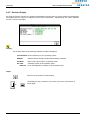
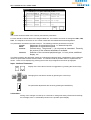
6.2.2 Definition of Access Opening
Before the initial operation of the machine, the number of the access opening must be defined. This is done
by user input in the screen “Access Opening”.
The screen "Access Opening" is selected by pressing the function key.
The screen contains fields, where numbers can be input in order to identify the access-ID for the host
communication, in which the position of the unit access opening position is defined. Further more unit
options can be released or inhibited via this mask.
Function description:
retrieval-ID -> Host
double retrieval
table options
safety bar
tray lock
This number helps a connected host pc to identify a retrieval.
Release of access with 2 levels -> in preparation!
Release of the following options:
- hinged table;
CPU-Software: C2S000-000 / 01.03.03-00;
OP-Software 1S08 or higher version
– tray full extraction; CPU-Software: C2S000-000 / 02.00.00-00;
OP-Software 2S00 or higher version
Release of a safety bar which protects the extractor area against unauthorised access -> in preparation!
Release of an additional locking mechanism in the access opening
CPU-Software: C2S000-000 / 02.00.00-00;
OP-Software 2S00 or higher version
Description of keys:
select option within the option area
Activate CURSOR- keys to select option field
58
Operator Manual OP2000 / C2000 - SHUTTLE
V 1.03 – 02/2002
BELLHEIMER METALLWERK GMBH
Service Mode
6.2.3 Modify Shelf Table
After the initialization run (Self-Learn), the control has saved a table, where all information concerning the
detected storage shelves, access(es), field reinforcements is deposited.
This table and its entries can be manually modified.
Input: Function keyè Branching into the sub-functions
Add an entry into the shelf table
Delete an entry from the shelf table
Display the shelf table – without modifications
Verify shelf for position
6.2.3.1 Adding an entry into the shelf table
! This function is implemented at a later point in time !
However, shelves can be added to the machine subsequently and at any time: By calling up an initialization
run ( Self-Learn, see chap. 6.2.1) the parameters of the shelves, e.g. the position of the corresponding shelf,
are detected by the control and the shelf table is updated.
6.2.3.2 Deleting an entry from the shelf table
! This function is implemented at a later point in time !
However, shelves can be removed from the machine subsequently and at any time. By calling up an
initialization run (Self-Learn,) the shelf table is updated.
V 1.03 – 02/2002
Operator Manual OP2000 / C2000 - SHUTTLE
59
Service Mode
BELLHEIMER METALLWERK GMBH
6.2.3.3 Display of shelf table – without modifications
The complete information belonging to a shelf entry is displayed on the following screen.
1.line
2.line
Shelf
Number of the current storage shelf
Area
The machine can be divided into several, logical storage areas..
At present, only 1 area is possible.
Shelf type
Differentiation between storage shelf, access(es), and unit reinforcements.
Side
Position of storage shelf front / rear inside the machine.
Grid
Relative position
Status
Shelves in the machine can be installed with a 25mm pitch.
In this field the pitch value of the corresponding shelf is displayed.
Shows the number of increments, from above and below, for the actual stop
position of the lift at a shelf.
A storage shelf can have the following conditions:
1. line
2. line
Free
Optimized
Height optimization è
Shelf is free for height-optimized storage.
Stored through
Optimized below
Height optimization è
Shelf is jointly used by storage goods located below.
Occupied
Optimized for tray
Height optimization è
Shelf is presently occupied by tray XX.
Free
Reserved for tray
Fix allocation è
Shelf is free, but reserved for tray XX.
Free
Reserved below
Fix allocation è
Shelf is free, but reserved for storage goods located below.
Stored through
Reserved below
Fix allocation è
Shelf is jointly used by storage goods located below.
Occupied
Fix allocation for tray
Fix allocation è
Shelf is occupied with fix allocation to tray XX.
Unknown
The automatic shelf recognition during the initialization run (SelfLearn) could not be allocated to a storage shelf, or access, or a field
reinforcement !
Possible problems with the shelf sensor on the extractor (tolerance
!?), or the machine type is incorrectly set up !
60
Operator Manual OP2000 / C2000 - SHUTTLE
V 1.03 – 02/2002
BELLHEIMER METALLWERK GMBH
Service Mode
Input: Function key
Display of the corresponding entry in the tray table.
Only possible if a tray is allocated !
Test of shelf positions, i.e. positioning of lift to the storage shelf preset in the field Shelf.
Display of the entries of the corresponding selection list
Scroll – up/down - in the shelf table to the next shelf number
6.2.3.4 Verify shelf for position
This function serves to inspect/correct shelf positions
Direction
determines direction of shelf positions to be corrected.
+/- Distance
correction value in mm.
Shelf
number(s) of the shelf/shelves to be corrected.
Selection:
V 1.03 – 02/2002
This one only
Shelf listed in field Shelf.
This one and all above
Shelf listed and all other shelves above.
All on the same side
Front or back, depending on entry in field side
all
All shelves independent of any entries.
Operator Manual OP2000 / C2000 - SHUTTLE
61
Service Mode
Input:
BELLHEIMER METALLWERK GMBH
Function key
Display of respective entries in shelf table
possible only after selection of valid shelf number in field Shelf !
Inspection of shelf positions.
When positioning a shelf (entry of same in field Shelf ) any value displayed in field +/distance respective thereof must be taken into account
Display of entries of the respective selection list
Scroll – up/down – in shelf table towards next shelf number
Correction !
Entries in the respective field are adopted and added to the shelf table.
Shelf table remains unchanged.
62
Operator Manual OP2000 / C2000 - SHUTTLE
V 1.03 – 02/2002
BELLHEIMER METALLWERK GMBH
Service Mode
6.2.4 Operation of the Connected Drive Control (Frequency Inverter)
During the first start-up, the standard parameters of the frequency converter are automatically downloaded
into the frequency inverter - adapted to the unit type mentioned at the time of initialization.
If, at a later date, possibly modified frequency inverter parameters have to be replaced by these standard
parameters, call up the menu "Frequency Inverter". This menu offers the possibility to replace the current
frequency inverter parameters by the standard frequency inverter parameters adapted to the machine type.
The menu "Frequency Inverter" is selected by pressing the function key.
This menu is only accessible to an authorized service technician! To an unauthorized person seeking
access the message "Access denied" is displayed.
The basic screen of the menu "Frequency Inverter" is shown as follows.
Input: Function key
Load standard adjustments (parameters) of the frequency converter
The standard adjustments of the frequency inverter parameters stored in the control are
loaded into the frequency inverter.
Since individually programmed frequency inverter parameters may have been deleted (cleared) during
loading, there will be a safety check query on the operator panel display. (see below).
V 1.03 – 02/2002
Operator Manual OP2000 / C2000 - SHUTTLE
63
Service Mode
BELLHEIMER METALLWERK GMBH
Input:
Do not start loading. The process is aborted. The previous screen is displayed.
Start loading by pressing the ENTER-key.
The loading of parameter values into the frequency inverter is confirmed by indication of the message
"Loading parameters" in the display.
After successful loading, the screen "Frequency Inverter" is displayed again.
64
Operator Manual OP2000 / C2000 - SHUTTLE
V 1.03 – 02/2002
BELLHEIMER METALLWERK GMBH
Service Mode
6.2.5 Modify Tray Table
The control has saved all information necessary to handle a tray. This tray and entries can be manually
modified.
Input: Function key è Branching into the sub-function
Add an entry to the tray table,
Delete an entry from the tray table,
Delete the entire tray,
Display the tray table – without modifications,
V 1.03 – 02/2002
Operator Manual OP2000 / C2000 - SHUTTLE
65
Service Mode
BELLHEIMER METALLWERK GMBH
Explanations concerning the tray table
Tray
Current tray number
Type
Tray type: With rollers on Shuttle 500/750/1000, without rollers on Shuttle 250.
This defines a different positioning of the lift.
Reserved
With fixed allocation mode, the shelf number is entered in this field. With optimized
Allocation, the shelf number is 0.
The height is the reserved maximum height, also with optimized storage.
Actual
Storage shelf, on which the current tray is stored, as well as the current height of the tray.
Extractor
Limitation of the extractor speed; 0-100%
Lift
Limitation of the lift speed; 0-100%
Weight
Limitation of the tray load; in kg
Input: Function key
Display of the corresponding entry in the tray table
Test of tray positions, i.e. positioning of the lift in correlation to the preset tray.
Display of detailed information
This function is implemented at a later time !
Display of the next / previous entry in the corresponding selection list
Scroll in the tray table to the next / previous tray number
66
Operator Manual OP2000 / C2000 - SHUTTLE
V 1.03 – 02/2002
BELLHEIMER METALLWERK GMBH
Service Mode
6.2.5.1 Addition of an entry to the tray table
Individual entries can be added to the tray table.
6.2.5.2 Deletion of an entry from the tray table
Individual entries can be deleted from the tray table.
Input: Function key è see explanations tray table
Abort a function without modification of the entries
Perform the function add / delete the current tray
V 1.03 – 02/2002
Operator Manual OP2000 / C2000 - SHUTTLE
67
Service Mode
BELLHEIMER METALLWERK GMBH
6.2.5.3 Deletion of tray table
With this function the entire tray table can be deleted.
ATTENTION !
This function destroys all information about possibly stored trays. These trays will no longer be known to the
control system and can no longer be retrieved into the access opening.
Input:
Abort function without modification, the table remains intact.
Perform delete function.
The table is then deleted, the control no longer recognizes a tray located in the
machine, and cannot retrieve/store it !!!
68
Operator Manual OP2000 / C2000 - SHUTTLE
V 1.03 – 02/2002
BELLHEIMER METALLWERK GMBH
Service Mode
6.2.5.4 Display of tray table – without modifications
Verification of entries in the tray table.
No modifications are performed.
Input: Function key / Softkey è see explanations tray table
Escape the function.
V 1.03 – 02/2002
Operator Manual OP2000 / C2000 - SHUTTLE
69
Service Mode
BELLHEIMER METALLWERK GMBH
6.2.5.5 Diagnostic Functions
Various diagnostic functions are available, in order to provide options, especially to the service personnel, for
setup procedures, error diagnosis, as well as maintenance, etc..
All machine units, which can be moved (actuators), are included with the diagnosis.
Input: Function key è Branching off into sub-functions
Locking
Tray extraction
Extractor
Lift
Safety shutter
70
Operator Manual OP2000 / C2000 - SHUTTLE
V 1.03 – 02/2002
BELLHEIMER METALLWERK GMBH
Service Mode
6.2.5.6 Locking System
Manual operation of the tray locking system, integrated sensory system. This option must be released in
mask "Access"
Tray
Number of trays in use
left/ right side
The following positions of the latch are indicated:
undefined
unlocked
locked
intermediate
hardware error in the locking system (sensory system motor)
positive message: " unlocked "
positive message: " locked "
position locking/unlocking process not completed, system still operating
The tray locking system is activated, whether a tray is sitting in the access opening or not
The tray locking system is de-activated, whether a tray is sitting in the access opening or not
Endurance run in this version is not activated.
V 1.03 – 02/2002
Operator Manual OP2000 / C2000 - SHUTTLE
71
Service Mode
BELLHEIMER METALLWERK GMBH
6.2.5.7 Tray extraction
Manual operation of the tray extraction system, integrated sensory system.
This option must be released in mask "Access" (see chapter "Unit access area" )
Tray
Number of tray in use
Finger Position
The following finger positions are indicated:
unknown
rear stop
front stop
between
hardware error (sensory system, drive)
positive message, finger of extractor in rear position
positive message, finger of extractor in front position
extraction movement not completed,
finger of extractor in intermediate position
move tray to front, from access on to table
move tray to rear, from table to access
endurance run in this version not activated
72
Operator Manual OP2000 / C2000 - SHUTTLE
V 1.03 – 02/2002
BELLHEIMER METALLWERK GMBH
Service Mode
6.2.5.8 Extractor
Manual operation of the extractor, the corresponding sensor equipment is included in the process.
The point of view is always starting from the point , where the operator stands.
“Forward“ always means transportation to the operator, also at a rear access !
„Backward“ always means transportation from the operator, also at a rear access !
Finger sensors
in the extractor
Tray
Number of a tray possibly sitting on the extractor.
Finger positions The various finger position options are displayed:
-
Top stop
Top front
Finger hold front
Front
Bottom stop
Rear
Finger hold rear
Top rear
Unknown
Input: Function key / Softkey
Extractor movement towards the front, e.g. tray from extractor or shelf onto access
Extractor movement toward the rear, e.g. tray from access or shelf onto extractor
Endurance run in this version not activated
Extractor manually (as long as key is pressed) position forward/back,
without taking into account the position sensor equipment.
Changes into menu "Lift"
V 1.03 – 02/2002
Operator Manual OP2000 / C2000 - SHUTTLE
73
Service Mode
BELLHEIMER METALLWERK GMBH
6.2.5.9 Lift
Manual operation of lift, the corresponding sensor equipment is included in the processes.
Shelf
Current shelf number resp. shelf to be driven to.
Incremental Encoder
Incremental value of incremental encoder è current position of lift.
Input: Function key / Softkey
Position lift to the first storage shelf entered in the shelf table.
Position lift to the last storage shelf entered in the shelf table.
Position lift to the storage shelf preset to the field Shelf .
Position lift to the current access workstation.
Position lift to the reference point of the machine (Zero reference point).
Position lift manually (as long as the key is pressed) upward/downward, without taking into
account the storage shelf positions.
Changes into menu "Extractor"
6.2.5.10
Safety shutter
! This function is implemented at a later time !
74
Operator Manual OP2000 / C2000 - SHUTTLE
V 1.03 – 02/2002
BELLHEIMER METALLWERK GMBH
Service Mode
6.3 General Adjustments
In the menu "Adjustment" parameter values used by the control can be adjusted.
The menu "Adjustment" is selected by pressing the function key.
Subsequently, the basic screen of the menu "Adjustment" is shown in the display.
Selection of function:
Use CURSOR-keys to select a function.
Press ENTER-key to activate selected function.
V 1.03 – 02/2002
Operator Manual OP2000 / C2000 - SHUTTLE
75
Service Mode
BELLHEIMER METALLWERK GMBH
6.3.1 Unit Adjustments
If multiple machines are operated in one network link (e.g. DB2000 with Ethernet-TCP/IP) a uniquely defined
label of each machine is necessary, to enable the controls to communicate with each other.
Input:
Logical machine numbers, label in network operation
The adjustments are taken over by pressing the ENTER-key.
76
Operator Manual OP2000 / C2000 - SHUTTLE
V 1.03 – 02/2002
BELLHEIMER METALLWERK GMBH
Service Mode
6.3.2 E-Data Buffer
After the function "E-buffers" has been selected in the menu "Adjustment", the screen "E-buffers" is shown
on the operator panel display (example: see below).
In this screen the maximum possible quantity of data records (data lines) per host buffer E1 and E2 is
shown. This value depends on the predetermined maximum possible length of the alphanumeric additional
information field, which is used during host communication. The length of the field can be adjusted in the
screen "Host"
For each buffer the quantity of records, which are yet to be processed, and the number of records, which are
ready to be recalled, are displayed.
Input: Function key
Deletion of records to be processed in E1
Deletion of records to be processed in E2
Deletion of processed records in E1
Deletion of processed records in E2
Deletion of all records in E1 and E2
V 1.03 – 02/2002
Operator Manual OP2000 / C2000 - SHUTTLE
77
Service Mode
BELLHEIMER METALLWERK GMBH
6.3.3 Host Adjustments
Adjustments of the string length used during host communication can be made in the screen "Host
adjustment".
After call-up of the function "Host " on the menu "Adjustment", the screen "Host adjustment" is shown in the
operator panel display (example: see below).
Input:
Enter length of the alphanumeric additional information field used in mode „Host
communication“.
Enter length of the quantity field, used in mode „Host communication“.
The switch from one input field to another is effected by means of the cursor
keys.
The performed adjustments are saved by pressing the ENTER-key.
78
Operator Manual OP2000 / C2000 - SHUTTLE
V 1.03 – 02/2002
BELLHEIMER METALLWERK GMBH
Service Mode
6.3.4 Set Date / Time
Date and time are maintened on the control and continue to run by means of a battery, even when the
machine is turned off.
Changes to the settings of date and time can be accomplished in the screen "Date/Time". After the function
"Date/Time" in the menu "Adjustment" has been selected, the screen is shown in the operator panel display
(example: see below). It shows the current time and date, at the moment the function item has been
selected.
Input:
Input of hours, minutes, seconds, month, day, year.
The CURSOR-keys are used to move between the fields time, day, month and
year.
Change between hour, minute and second within the field time.
The process is aborted. The settings remain unchanged. The previous screen is
shown.
Starting of the set time and date with second precision.
ATTENTION !
If no changes are to be made, the screen must be left by means of the
key.
Since time continues to run in the background but is not shown updated on the display,
leaving by the ENTER-key would have the effect of setting the time back.
V 1.03 – 02/2002
Operator Manual OP2000 / C2000 - SHUTTLE
79
Service Mode
BELLHEIMER METALLWERK GMBH
6.3.5 Interface Definition
The definition of interface parameters used for connections with computer systems, barcode readers,
printers, scales, etc., occurs in the menu "Interface".
After selecting the menu "Interface" in the menu "Adjustment", the screen "Interface" is shown in the operator
panel display (example: see below).
Input: Function key / Softkey - Selection of interface
Serial Interfaces (RS232, RS422 etc.) . Normally used for connection with barcode
readers, printers, etc., but also with computer systems.
Ethernet (Local-Area-Network-Interface LAN) – Option (in preparation).
Normally used for linking with computer systems.
Testing of a printer connected to a serial interface.
The printer has to be assigned to the interface.
6.3.5.1 Adjustments – Serial interface
With the base control, 2 serial interface channels are available. According to each required function the
channels have to be initialized accordingly. This can be done within the screen "Set parameter".
The screen "Set parameter" is selected by pressing the function key F1 reserved by
Then the screen appears in the display (example: see below).
80
Operator Manual OP2000 / C2000 - SHUTTLE
.
V 1.03 – 02/2002
BELLHEIMER METALLWERK GMBH
Service Mode
The screen shows the table of the currently set interface parameters.
For each interface channel there is an assigned table line. The interface channels are designated CH1, CH2,
CH3. The respective connectors on the control module are also labeled with these designations.
The parameters are listed in the table columns. The following interface parameters are shown.
Format:
Adjustment of transmission format, i.e. data and stop bits.
Baud:
Adjustment of transmission speed.
Protocol
Protocol setup. The protocol (---) is not preset as a standard. Presently,
Function:
the protocol of the software handshake is available.
Selection of the connected peripheral type, i.e. host, printer, additional
display, etc.
The fields containing the parameter values are organized as selection fields. Modifications of the parameter
values are performed via these selection fields. In a selection field all possible values of a parameter are
shown. These can be displayed by pressing the function keys assigned to the shown pictographs.
Input: Interface Parameters
Display of the next value in the list of suggestions by pressing the function keys.
Changing from one field to another by pressing the cursor keys.
The performed adjustments are saved by pressing the ENTER-key.
ATTENTION !
Storing of the changes can take up to 2 seconds. If storage has been performed successfully,
the message „Done“ is momentarily shown on the operator panel display.
V 1.03 – 02/2002
Operator Manual OP2000 / C2000 - SHUTTLE
81
Service Mode
BELLHEIMER METALLWERK GMBH
6.3.5.2 Adjustments – Ethernet-TCP/IP
For the networking of multiple machines, e.g. for the administration with DB2000, the Ethernet interface and
transmission protocol TCP/IP are used.
This network is structured according to the „Client/Server-principle“, which means that a central control (the
server )manages one or more users (or clients).
Example: A database manager, which is centrally installed on the server, which comprises all
functionalities, which are necessary for the complete data handling, multiple users communicating with the
central data base on one input/output unit.
The networking with Ethernet-TCP/IP presupposes that to each control in the net an Ethernet-address as
well as an IP-address is assigned. These addresses are necessary to enable the controls (network nodes)
to communicate with each other via a uniquely defined label.
The Ethernet-address is preset at the factory, it is invisible/not modifiable by the user. It is handled like this
for safety reasons, in order to prevent duplikate assignments of Ethernet-addresses, it is important, e.g.
when an existing network cabling is jointly used.
For the CONTROL C2000, a uniquely defined number cycle is allocated, which exists only once worldwide.
The IP-address can be freely selected, in the case that the machines are networked directly with each other
with their own cabling.
If an already existing network cabling of the customer’s should be jointly used, the assignment of the
IP-addresses must be coordinated with the customer’s network administrator !
„Own
IP-Address“
Label of the „Own“ Machine/Control – Client.
„Server IP-Address“
Label of the Machine/Control, where the database is installed – Server.
„Standard-Gateway
IP-Address“
Label of the „Interchange point“, in case that an existing network cabling
is jointly used, and that the access is controlled via a Gateway.
82
Operator Manual OP2000 / C2000 - SHUTTLE
V 1.03 – 02/2002
BELLHEIMER METALLWERK GMBH
Service Mode
Input: Function key
Activate the network after turning the machine OFF / ON.
Before, the IP-addresses have to be set up !
Setup of IP-addresses.
Recommendation for the IP-addresses è only usable with own cabling !!!
- Own IP-addresses:
- Server IP-address:
192.168.10.12 – 192.168.10.17
192.168.10.11
Changing between the entry fields with the CURSOR-keys.
Entry DOT.
The structure XXX.XXX.XXX.XXX of the IP-address is pre-assigned.
The process is aborted. The setups remains intact..
Confirmation of entry. The setups are saved.
V 1.03 – 02/2002
Operator Manual OP2000 / C2000 - SHUTTLE
83
Service Mode
BELLHEIMER METALLWERK GMBH
6.3.6 Change Password
After the selection of the menu "Change Password" in the menu “Adjustments”, the selection screen of this
menu is shown in the operator panel display.
Functions to change the "Customer's Service password"; "Database Password" and "User-AdministrationPassword" are offered.
Call-up of a Function:
Select a function by means of the CURSOR-keys.
The selected function item is started by pressing the ENTER-key.
The password is changed in both functions according to the same systematics. It is described with the help
of an example for the change of a "Customer's service password" as follows. The change of "Database
Password" and "User-Administration-Password" are performed analogously.
After selection of the function the following screen is shown in the display.
84
Operator Manual OP2000 / C2000 - SHUTTLE
V 1.03 – 02/2002
BELLHEIMER METALLWERK GMBH
Service Mode
In order to change a password, the old password (,i.e. the current password, which is to be changed,) and
the new password (,which is to be used in the future) have to be entered into the respective fields.
All strings produced via numeric keys and function keys are permissable. A string may not contain more
than 8 characters. The entry of the passwords occurs hidden, i.e. in order to protect against unauthorized
viewing, instead of the entered character a star ( ) is put out on the display.
*
Input: Change password
Input of password.
The input fields for old password and new password are changed by pressing
the CURSOR-keys.
The entered change of the password is taken over by pressing the ENTERkey.
The process is aborted. The settings remain unchanged. The previous
screen is shown.
ATTENTION !
It is mandatory that the new password has been entered into the provided field, before
pressing the ENTER-key, since otherwise the access is no longer protected by a password.
V 1.03 – 02/2002
Operator Manual OP2000 / C2000 - SHUTTLE
85
Service Mode
BELLHEIMER METALLWERK GMBH
6.3.7 Delete Database
The function "Delete Database" deletes the database buffer of the internal "Article Storage Location
Administration "DB2000".
After the selection of the function "Delete Database" in the menu "Adjustment" the following query is shown
in the operator panel display.
Input:
The process is aborted. The previous screen is shown.
Starting of the deletion process by pressing the ENTER-key.
After the deletion, the screen "Adjustment" is shown again in the operator panel display.
86
Operator Manual OP2000 / C2000 - SHUTTLE
V 1.03 – 02/2002
BELLHEIMER METALLWERK GMBH
Service Mode
6.3.8 Setup of Travel Speed
The maximum travel speed for the extractor and lift can be defined, within the range of 10-100%.
This functionality can be necessary, e.g. for storage of sensitive parts, liquids, etc.
Setup of standard values for the horizontal and vertical speeds.
In chap. „Modify trays“ , these values can be individually adjusted for each tray.
Input:
Enter values for
- Horizontal speed è Extractor and
- Vertical speed è Lift
With these keys it is possible to switch back and forth between the entry fields with
the CURSOR-keys.
Entries are taken over and saved.
The process has been aborted. The setups remain intact.
V 1.03 – 02/2002
Operator Manual OP2000 / C2000 - SHUTTLE
87
Service Mode
BELLHEIMER METALLWERK GMBH
In case modifications were made regarding vertical or horizontal speed (or both), followed by pressing of the
[ENTER] button, the following message is displayed:
When [ENTER] button is pressed again, all trays with old horizontal and vertical speed standard value
allocations are updated to after-modification speed.
Example:
Modifications of standard values in mask "speed"
horizontal speed:
50% (old) Þ 67% (new)
70% (old)
vertical speed:
Þ 100% (new)
Details tray table:
before modification
traynumber
1
2
3
4
old horizontal
speed
50%
50%
20%
80%
new horizontal
speed
70%
20%
70%
60%
after modification
old vertical
speed
67%
67%
20%
80%
new vertical
speed
100%
20%
100%
60%
After modifications to the tray table, the following message is displayed for a short time:
88
Operator Manual OP2000 / C2000 - SHUTTLE
V 1.03 – 02/2002
BELLHEIMER METALLWERK GMBH
Service Mode
6.4 Endurance Run
For demonstrating and testing purposes there is an endurance run available, which is started in the menu
"Endurance Run".
The menu "Endurance Run" is called up by pressing the function key reserved by
.
This menu is only accessible to authorized service technicians! Without authorization, the message
"Access denied" is shown.
After selection of the function, the entry screen "Endurance parameter" is shown.
In this screen, values for the following parameters of the endurance run have to be entered:
·
Definition of tray numbers for the max. 3 trays used by the endurance-run function.
·
Delay time 1: This is the time (in seconds), which the machine uses to pause before the (n+1)th
retrieval. (n = 0, 2, 4, 6, ...)
·
Delay time 2: This is the time (in seconds), which the machine uses to pause before the (n+2)th
retrieval. (n = 0, 2, 4, 6, ...)
Abortion of function "endurance run". Possible only, if a tray is sitting in the access opening.
V 1.03 – 02/2002
Operator Manual OP2000 / C2000 - SHUTTLE
89
Service Mode
BELLHEIMER METALLWERK GMBH
Input: Endurance Run (Parameters and Start)
The values of the endurance run parameters have to be entered by means of
the numeric keys.
The switch from one input field to another is effected by means of the cursor
keys.
The endurance run is started and carried out according to the set values.
During the endurance run the "Positioning Screen" is shown in the display of the operator panel.
ATTENTION!
While an endurance run is performed, the machine moves automatically, therefore it is
especially important to assure that sufficient safety measures are taken. Persons or objects
have to be prevented from entering the access area by appropriate barring and displaying of
information signs. During the endurance run, the machine should not be without supervision.
The endurance run can only be concluded, if a tray is located in the access opening.
The endurance run is aborted.
After the endurance run has been aborted, the screen "Endurance parameter" is shown again on the
operator panel display.
90
Operator Manual OP2000 / C2000 - SHUTTLE
V 1.03 – 02/2002
BELLHEIMER METALLWERK GMBH
Service Mode
6.5 User Administration
Ein Zugriff in die Benutzerverwaltung erfolgt nur durch den Verwalter oder dem Servicetechniker.
Siehe Anhang D „Benutzerverwaltung“
6.6 Save Service Date
The control C2000 stores the machine’s operational data with reference to the last initialization and the last
service. These data can be shown in the menu "Information. In order to communicate to the control that a
service has taken place, the function "Save Service Date” must be performed.
The function "Save Service Date" is selected by pressing the function key.
This function is only accessible to an authorized service technician!
The function "Save Service Date" allows the service technician to leave the service mode without having to
turn off the machine (log-in ID. is reset, the service mode is accessible only by re-entry of the password).
V 1.03 – 02/2002
Operator Manual OP2000 / C2000 - SHUTTLE
91
BELLHEIMER METALLWERK GMBH
Annex A
Hinged Table (Option)
A General Information concerning option „Hinged Table“
The hinged table is mounted to the access opening. If the table is folded up and latched correctly and the
table option on the operator panel has been released, the tray, which has already been transported to the
access opening, will be unlatched.
The operator can then extract the tray from the access opening of the unit on to the table.
Switch
1S2 and 1S3
1S4 or (1S4 and 1S7)
Significance
table folded up
table folded down
Software Requirements
Activaton of the hinged table, requires the following software versions:
· CPU-Software C2S-01.03.01-00 or higher version
· OP-Software 1S08 or higher version
V 1.03 – 02/2002
Benutzer-Handbuch OP2000 / C2000 - SHUTTLE
A-1
Annex A
Hinged Table (Option)
BELLHEIMER METALLWERK GMBH
Release of Option Hinged Table
Activation of this option requires prior release. Release is effected via menu Service, Unit, Retrieval
Press function key [F2].
Press function key [F2].
Move cursor towards menu item Table Options and press functions keys [F5] or [F6] to choose option
Hinged Table. Confirm with [ENTER]-button.
Enter [ESC]-button three times to return to the Basic Menu.
A-2
Benutzer-Handbuch OP2000 / C2000 - SHUTTLE
V 1.03 – 02/2002
BELLHEIMER METALLWERK GMBH
Annex A
Hinged Table (Option)
Operational Modes
Table option Hinged Table has not been released or table is folded down
A try, which sits in the access opening can be manually unlatched by activation of function key [F6] in
Manual Mode.
If this tray is then completely removed from the access opening, the current tray number is deleted from both
tray table and display. The tray is therefore retrieved and has become invalid for the control system.
When restoring this tray, the number must be re-entered.
Table option Hinged Table has been released and table is correctly folded up
Immediately after the machine operator has ordered a tray into the access opening via the manual, host or
data base menu, the current status of the table is evaluated by the control system.
If the table is properly locked, the tray is unlatched automatically and is ready to be transferred on to the
table. The number assigned to this tray remains valid for the control system.
Should one of the errors listed below appear, the tray will remain locked
Options for unlatching a tray
In order to transfer a tray on to the table, the tray must have been previously unlocked
1. Option:
A tray, which has been previously transferred into the access opening, is automatically unlocked via the
manual, host or data base menu if the table is completely folded up, correctly latched and the table
option in the display unit of the software has been released.
2. Option
In hand mode a tray sitting in the access opening is unlatched manually, when function key [F6] is
activated.
Restoring an unlatched tray
A tray can only be restored if it is positioned completely in the access opening. If the tray (or part thereof) is
still on the table, the following message appears:
After a tray has been transported into the access opening, it will be restored when the [ENTER]-key is
pressed.
V 1.03 – 02/2002
Benutzer-Handbuch OP2000 / C2000 - SHUTTLE
A-3
Annex A
Hinged Table (Option)
BELLHEIMER METALLWERK GMBH
Possible error conditions
When, in manual mode, a tray was supposed to be unlatched via activation of function key [F6], the following
error codes can be displayed.
1. Error message:
Cause:
Table is in intermediate position
Switches 1S2 and 1S3 were not activated or switches 1S4 o 1S4 / 1S7 are not occupied.
(see mechanical draft)
2. Error message:
Cause:
Table position not definded / switches defect
Switches 1S2 and 1S3 as well as switches 1S4 and/or 1S4 / 1S7 are switched.
(see mechanical draft)
Remedy:
Check switches 1S2 und 1S3 as well as switches 1S4 and/or 1S4 / 1S7.
The switches 1S2 und 1S3 are connected in series and wired to IN 24.
The switches 1S4 und 1S7 are connected in series and wired to IN 25.
Die inputs IN24 und IN25 on the MIF GS201(Machine-Interface) must have the following conditions:
input IN 25
input IN 24
condition IN 25
condition IN 25
logical 0
logical 1
logical 1
logical 0
green LED an
green LED aus
green LED aus
green LED ein
A-4
meaning
table up
table down
Benutzer-Handbuch OP2000 / C2000 - SHUTTLE
V 1.03 – 02/2002
BELLHEIMER METALLWERK GMBH
Annex B
M-buffer function
B M-buffer function
Available with firmware version 02.04.00-00
In Manual buffer as many as 200 location data lines can be stored. It is possible to scroll through the list and
modify, attach or delete datalines.
In case there are data stored in the M-buffer, they can be executed sequentially in manual mode. A dataline
is deleted from the M-buffer, when the destination is reached
If data records are available in the Mbuffer, theM-icon flashes in manual
mode.
Data records are processed, if no
tray entries were made.
How to activate the M-buffer menu
In manual mode an M-icon is displayed. Select this icon with the cursor keys and confirm with
ENTER key to activate the M-buffer menu.
Access
Selecting an access opening
Selecting an access opening in a unit with multiple access openings.
The M-buffer can be processed for each access opening individually.
Topical
Selecting a data record
Displays the data record currently being processed. Use this field to select a data record.
V 1.03 – 02/2002
Benutzer-Handbuch OP2000 / C2000 - SHUTTLE
B-1
Annex B
M-buffer function
BELLHEIMER METALLWERK GMBH
Inserting a data record
A data record is inserted before the data record currently on display in the M-buffer list
Modifying a data record
A currently displayed data record is modified.
Deleting a data record
The current data record is deleted in the M-buffer list
Deleting the M-buffer
All entries in the M-buffer list of the current access opening are deleted.
Scrolling the M-buffer
Scrolling in the M-buffer list of the current access opening
Sorting the M-buffer
·
·
B-2
sorting tray numbers in ascending order
sorting shelf numbers in ascending order
Benutzer-Handbuch OP2000 / C2000 - SHUTTLE
V 1.03 – 02/2002
BELLHEIMER METALLWERK GMBH
Annex C
Data Backup on PC-Flash-Card
C Data Backup on PC-Flash-Card
Option PC-Card-Memory enables a data backup of DB2000-article –storage location -data.
The backup is done manually, this includes storing the data on PC-Card-Memory, „Backup“, as
well as re-storing data back („Restore“) in case of loss of data in the control.
Automatic data backup is not possible with this option!
The PC-Flash-Card allows data storage of up to 5 units, and per unit, the creation of up to 5
backup generations.
Replaceable, flexible PC-Flash-Cards are used as
storage medium.
The PC-Card-Memory is connected via an adapter to
the and can be activated in the relevant service menu
of the OP2000 by an authorized service technician.
How to activate the backup editor
.
After choosing menu item „memory card“, the
inzialisation of PC-CARD-Memory is made, the
system is thus activated.
Once the PC-card editor is activated, the menu switches over to data-backup editor.
V 1.03 – 02/2002
Operator Manual OP2000 / C2000 - SHUTTLE
C-1
Annex C
Data Backup on PC-Flash-Card
BELLHEIMER METALLWERK GMBH
How to operate the back-up editor
.
The mask shows no entry, i. e. data have
not been stored on the Flash-Card!
Restore data from the Flash-Card
Backup C2 – is not supported with this firmware version!!!
Backup DB – Backup of DB2000-data on Flash-Card
Select an entry in the editor
Change into selected (sub)-directory
Quit function, and change into superior directory
C-2
Operator Manual OP2000 / C2000 - SHUTTLE
V 1.03 – 02/2002
BELLHEIMER METALLWERK GMBH
Annex C
Data Backup on PC-Flash-Card
Backup of DB2000 data
.
The DB2000-data structure is divided in 3 blocks (files) – these are stored.
ARTICLES.DB
POSITION.DB
SIZES.DB
article data
storage location data
location size
DB2000- Backup
Creating a file
The structure on the Flash-Card is comparable with the PC-DOS- or Windows-filestructure on a hard disk or disk, i. e. files are stored in pre-defined directories. The
name of directories results from the CPU-Number of the control.
Quit function, a directory has not been set up !
Confirmation, a directory is set up
The following information is displayed:
A:\00102412.CPU\DB
00102412
DB
Directory
CPU number of unit with data backup
sub directory, marks data backup
0.DB
< DIR >
Backup generation 0 (0...99999999) DB2000 data
Directory
(in case of a file, its size is indicated)
date and time when directory was set up
.
09-25-2001 12:53:02
V 1.03 – 02/2002
Operator Manual OP2000 / C2000 - SHUTTLE
C-3
Annex C
Data Backup on PC-Flash-Card
BELLHEIMER METALLWERK GMBH
How to create a Backup generation
Maximum 5 backup-generations of 5 units can be stored, beginning with generation 0
( file: 0.DB ).
From the 6th backup-generation, the oldest generation is deleted automatically and
the new one is stored according to the principle „Child-FatherGrandfather ...“
1. Data backup è 0.DB
th
After the 5 data backup
è 0.DB ....... 4.DB
th
After the 6 backup
The 'oldest' backup 0.DB
is deleted, the 'new' backup 5.DB is
stored è 1.DB ...... 5.DB
C-4
Operator Manual OP2000 / C2000 - SHUTTLE
V 1.03 – 02/2002
BELLHEIMER METALLWERK GMBH
Annex C
Data Backup on PC-Flash-Card
Select / mark a directory and press return key to display the stored files.
Select entry in editor
The size of a file is an important note
for successful back-up, indicated in
number of characters. When size=0 is
indicated, no data-Server is
activated !!!
V 1.03 – 02/2002
Operator Manual OP2000 / C2000 - SHUTTLE
C-5
Annex C
Data Backup on PC-Flash-Card
BELLHEIMER METALLWERK GMBH
Restore DB2000 data
.
DB2000 – Restore
The files can be individually restored into the memory of the C2000.
Select file to be restored
A marked file is restored into the control by the PCCARD-data backup.
With successful restorage, the following message is
displayed „done“.
C-6
Operator Manual OP2000 / C2000 - SHUTTLE
V 1.03 – 02/2002
BELLHEIMER METALLWERK GMBH
Annex C
Data Backup on PC-Flash-Card
Error-No. Description::
100
File name has no correct extension
101
File name is illegal
102
File name contains illegal characters.
103
File name contains more than 8 characters
104
Path contains illegal characters
105
Drive name contains illegal characters
106
Drive name contains no back-slash \.
107
When testing the extension, an illegal character was recognised
108
When testing the extension, more than 3 characters were recognised
109
When extracting the path, no extension and no file name were recognised
110
File name has no correct extension
111
Logical path is incorrect
112
Maximum Backup files (99999999) reached
REMEDY: 99999999 re-name to 4
99999998 re-name to 3, etc.
113
Target could not be opened on RAM-Disk (C2000)
114
Target could not be closed on RAM-Disk (C2000)
115
Old database backup could not be deleted
116
Old C2000 backup version could not be deleted ( with next release )
117
Maximum number of backup files or paths was reached
118
An authorised attempt was made to re-store a file (either no *.dat extension or
incorrect CPU-number).
119
It was recognised that a CPU number is not compatible with the machine..
V 1.03 – 02/2002
Operator Manual OP2000 / C2000 - SHUTTLE
C-7
BELLHEIMER METALLWERK GMBH
Annex D
User management
D User management for SHUTTLE NT
User management determines and controls access to a unit, i.e. it authorises or denies access to individual
users.
It is possible to administer a maximum of 30 users names.
Each user must once be made known to the control by the administrator. Via a special „administrator
password,“ the administrator gains access to the initialisation area of the user management.
For each single user, the administrator can:
·
·
·
release / deny an access opening
release / deny access to a tray or part of a tray
release / deny sub-menus „Host communication“, „basic operation“, „DB2000-data base“.
Unit operation with active user management
A user is registered via a user password which has previously been determined by the administrator.
Registration can take place via:
·
·
·
data entry into the OP2000 keyboard
barcode reader and the respective barcode labels
chip card reader and the respective chip cards
If the entered password is recognised by the control,
the user enters the basic menu. In accordance with
the user rights previously determined, the unit is now
ready for further operation.
V 1.03 – 02/2002
Benutzer-Handbuch OP2000 / C2000 - SHUTTLE
D-1
Annex D
User management
BELLHEIMER METALLWERK GMBH
Main Menu Selection
From this menu, 5 main menus are selected.
The main-menu selection screen can be selected from every submenu by pressing (multiple times, if
necessary) the
key.
Symbol of
logged-in user
user name
user-no.
Input:
Function key
Branching into the main menus.
Note: Branching is possible only if the user has the respective access authorization.
Select “Basic Operation” (Manual Mode).
"Article-Storage-Administration – DB2000" (Option).
"Host Communication
"Service Mode
"Information system
User log-out
After log-out, the user log-in mask is
displayed the operator panel, the unit is
now ready for user log-in again.
D-2
Benutzer-Handbuch OP2000 / C2000 - SHUTTLE
V 1.03 – 02/2002
BELLHEIMER METALLWERK GMBH
Annex D
User management
Denying / releasing access rights to sub-menus
The administrator can deny /release access to the following sub-menus:
· Basic operation – manual mode
· Article–storage-administration
· Host communication
If access is denied to one of the above-mentioned sub-menus, the following message is displayed after
pressing the respective function keys:
Denying access to individual users
The administrator can deny access to any user.
After entering the password and confirmation
with the [ENTER]–button, the following message is displayed:
The administrator registers by entering his administrator password.
If the entered password is recognised by the control, the
administrator directly enters the user administration area. Here,
he can assign/define user and access rights, introduce new
users to the control and delete existing ones.
V 1.03 – 02/2002
Benutzer-Handbuch OP2000 / C2000 - SHUTTLE
D-3
Annex D
User management
BELLHEIMER METALLWERK GMBH
Administrator Rights
First it is necessary to authorise a person as administrator. The administrator cannot operate the unit with his
password. He can only use his password to enter, modify of delete user names.
If user names have not been entered, the basic menu is displayed directly.
The administrator presses function key [F4] to call up Service-Mode.
Enter user administration password 007 to activate User management.
If this menu is activated, the administrator can reach other menus by pressing the respective function keys.
He chooses the respective users by pressing function keys [F5] and [F6] or by entering a number between 1
and 30.
D-4
Benutzer-Handbuch OP2000 / C2000 - SHUTTLE
V 1.03 – 02/2002
BELLHEIMER METALLWERK GMBH
Annex D
User management
Enter new user name
In order to enter a new user name, enter a number between 1 and 30 and press the [ENTER]-button.
Then press function key [F1] and enter a user name and password.
The name can consist of maximum 16 alphanumeric digits (optional).
The password must consist of minimum 3 alphanumeric digits and can consist of maximum 8 digits.
Enter a new user name and press the [ENTER]-button. The menu for the assignment of access rights is
displayed.
When this menu appears for the first time, the following settings have already been determined for the
selected user:
·
·
·
·
·
Release of all access openings.
User can log in all 6 access openings
Release of Manual Mode
In Manual Mode, a user can retrieve and restore individual trays
Release of Host Dialogue
Host dialogue is accessible from basic menu.
Release of functions of the Database option
It is possible to retrieve, restore and administer articles
all trays are blocked !
In order to release trays for the selected user, move the cursor to menu item Release trays.
Use numeric keys to enter beginning of the area , move cursor to the right and enter end of the area.
After moving the cursor to the relevant position, it is possible to lock/release retrievals and different modes
by pressing function key [F6].
Press the [ENTER]-key to store modifications. To escape this menu, press the [ESC]-button.
V 1.03 – 02/2002
Benutzer-Handbuch OP2000 / C2000 - SHUTTLE
D-5
Annex D
User management
BELLHEIMER METALLWERK GMBH
Change User Name and/or Password
Press function key [F1] to activate the menu in which it is possible to change a user name and/or password.
Press the [ENTER]-button to store all modifications.
Press the [ESC]-button to return to menu 'User management'.
Change Access Rights
Select user.
Press function key [F2] to activate the menu in which it is possible to change the access rights.
By pressing function key [F6]. it is possible to release/lock all functions mentioned, with the exception of tray
release/ tray lock (disable tray / enable tray) 'Release' ('enable') is marked with a cross.
D-6
Benutzer-Handbuch OP2000 / C2000 - SHUTTLE
V 1.03 – 02/2002
BELLHEIMER METALLWERK GMBH
Annex D
User management
Release or Block Access Area
A user can only log on in an access area which has been released to him.
Example:
Access areas 2 to 6 have been released, access area 1 is blocked. If a user tries to log on in access area 1,
the following message is displayed:
Access denied to user!
Block Tray
To block a selected range of trays, it is necessary to enter the numbers of the first and the last tray.
Example:
Enter selected range Block Trays 1 to 10
To block one tray only, entry of one value only is sufficient
Example:
Enter Block trays 1 to 0
If a user tries to retrieve a blocked tray into the access opening, the following message is displayed:
Tray denied to user!
Release Tray
To release a selected range, enter numbers of the first and the last tray.
Example:
Enter selected range Release trays 5 to 15
To release one tray only, entry of one value only is sufficient
Example
Enter Release trays 1 to 0
Release or lock Manual Mode
If this mode is released, the user can perform basic operations.
Release or lock Host Dialogue
If this dialogue is released, the operator can receive and process information from a supervisory computer
system via host communication.
Release or lock Storage and Retrieval
If this option is released, the operator can store and retrieve articles in the Article Storage Location
Administration.
This option is in preparation!
Process articles
If this option is released, the operator can process articles in the Article Storage Location Administration.
This option is in preparation!
NOTE:
Press [ENTER]-button to store all modifications.
Press the [ESC]-button to enter User management.
V 1.03 – 02/2002
Benutzer-Handbuch OP2000 / C2000 - SHUTTLE
D-7
Annex D
User management
BELLHEIMER METALLWERK GMBH
Delete User
Select user. After pressing function key [F3] the following message is displayed
ENTER: yes ESC: no.
Press the [ENTER]-button to delete the current user.
Change User Administrator Password
Press function key [F4] to change to Change Password menu
To change the User Management password, the old password and the new password must be entered into
the corresponding fields. Data are entered with hidden letters and can be alphanumeric.
Press [ENTER]-button to return to menu 'User Management'.
D-8
Benutzer-Handbuch OP2000 / C2000 - SHUTTLE
V 1.03 – 02/2002
BELLHEIMER METALLWERK GMBH
Annex D
User management
User management with external periphery
Apart from entering data directly into OP2000, user registration is also possible via a barcode or chip card
reader.
The input devices are connected to control C2000 via serial interface RS232. Each required interface
channel must be initialised before first application of the reading devices.
Barcode reader
When storing, modifying and registering a user, it is possible enter the user password via barcode reader,
Chip card reader
A user can register at a unit via chip card or, as the standard feature, by entering his password into the
operator panel log-on mask.
This option is available with firmware version
è Shuttle
02.04.00
User name and an individually assigned user password are
stored on the chip card. During log-on, these data are
transmitted to the user administration.
These identity cards are equipped with an integrated
chip, comparable with telephone, insurance or company
cards or similar means of identification.
Peter Smith
V 1.03 – 02/2002
Benutzer-Handbuch OP2000 / C2000 - SHUTTLE
D-9
Annex D
User management
BELLHEIMER METALLWERK GMBH
Reading a chip card – User registration
.
A user has activated the log-on mask in 'User Management'.
(for testing purposes: Quit ' User Management' and, in menu 'Service', press function key F6 – „Save Service
Data“)
If the recorded chip card is correctly inserted into
the chip card reader,
the basic menu is displayed along with the user
name.
Recording a chip card
.
In menu „Service- User Management“, sub-menu „Name and password“ is activated
Here, all user-relevant data (user name and password) are assigned.
Press „ENTER“ to change over to menu „Access“.
After correct connection and
configuration of the chip card
reader, the symbol of a chip card is
displayed..
If the chip card symbol is not available, activate menu „Service- AdjustmentInterface- Serial- set Parameter“ and check the configuration.
D-10
Benutzer-Handbuch OP2000 / C2000 - SHUTTLE
V 1.03 – 02/2002
BELLHEIMER METALLWERK GMBH
Annex D
User management
Recording procedure
.
Press function keyAll relevant data are prepared to be recorded on to the chip card.
The symbol of the chip card is reversed and flashes.
The symbol of the chip card is
reversed and flashes.
The chip card is inserted into the card reader, towards the LED.
If it is inserted correctly, the user password and name are stored on it. The LED is activated during the
recording procedure.
The recording procedure lasts about one second. After recording has been completed, the LED is
deactivated.
Remove the chip card from the chip card reader.
The user data are now stored on the chip card.
After the writing process has been
completed, the chip card symbol
returns to its normal state.
V 1.03 – 02/2002
Benutzer-Handbuch OP2000 / C2000 - SHUTTLE
D-11
BELLHEIMER METALLWERK GMBH
Annex E
Weight Management
E Weight Management
Available with firmware version 02.04.00-00
Integrated weight management allows the operator to have both single tray load and total load
of a unit displayed.
At the moment, it is possible to select between the following units of weight for load display:
kilogram or pound.
Option 'Weight Management' can only be activated in units equipped with
one single standard tray type: type 1, 2 or 3. It is not suitable for operations
with different tray types!
Tray load and unit total load are determined when a tray is being stored / re-stored.
If tray load and unit total load are within the admissible limits, the tray is stored.
Option 'Weight Management' prevents a tray or the total unit from being overloaded.
In case of tray/unit overload, the tray is not re-stored and a message is displayed on the
operator panel.
This functionality applies to the following operational sequences:
·
·
·
·
·
when a tray is re-stored in Manual mode.
when a tray is re-stored during Host communication
during tray transfer between different access openings
when a tray is re-stored in Article storage administration – DB 2000
when a tray is re-stored in sequence „Learn tray“ in height-optimized mode.
Weight display
Load weight is indicated on the OP 2000 display after the test run, during the re-storing
process.
The operator can select a unit of weight - kilogram (kg) or pound (lb) - in menu Service,
Adjustment, Weight Management.
V 1.03 - 01.2002
Operator Manual OP2000 / C2000 - SHUTTLE
E-1
Annex E
Weight Management
BELLHEIMER METALLWERK GMBH
Overload display
If the admissible tray load or the total admissible load capacity are exceeded, the tray is transported back
into the access opening and the following error message is displayed:
Tray load exceeds admissible tray load. Decrease
tray load.
Total load of all tray exceeds admissible total
load.
Activate / deactivate option 'Weight Management'
For some applications, active ' Weight Management' can be a disturbing element. In the following section,
please find a description of how to activate / deactivate 'Weight Management'.
ATTENTION – With deactivated option „Weight Management“, there is
NO control / monitoring of tray load or total unit !!
Select option „aktiv / not aktiv“.
Confirm selected entry in list.
Entry is valid
Quit function or change into superior directory.
Entry is not valid
E-2
Operator Manual OP2000 / C2000 - SHUTTLE
V 1.03 - 01.2002
BELLHEIMER METALLWERK GMBH
Annex E
Weight Management
The individual parameters have the following significance:
When entering the „Customer-Service password“, it is possible for the operator to define /
alter these parameters .
Option enable (active) ?
Activate / deactivate option 'Weight Management'
Unit of weight
Unit of weight in load display: kilogram kg or pound lb
These parameters can only be defined / altered by an authorised service technician!
Offset
This parameter is automatically defined by the TARE-function. Entry
not required!
Total load
The total load is the sum total of all admissible tray loads..
This parameter must comply with the details on the type
identification label. ENTRY REQUIRED!
Admissible load per carrier
The load per carrier is the maximum average load per tray, which can
be evenly distributed on the tray surface. For trays with standard
depths and widths, this parameter is automatically calculated!
For trays with non-standard dimensions, this value must be
entered manually, in compliance with the data sheet attached to
the unit documentation
Tray dead weight
To calculate the tray load, the tray dead weight is subtracted from the
measured values.
For trays with standard depths and widths, this parameter is
automatically calculated!
For trays with non-standard dimensions, this value must be
entered manually,
in compliance with the data sheet attached to the unit
documentation.
current load
front
This parameter is used to display the total load at the front side of the
unit.
current load
rear
This parameter is used to display the total load at the rear side of the
unit.
V 1.03 - 01.2002
Operator Manual OP2000 / C2000 - SHUTTLE
E-3
BELLHEIMER METALLWERK GMBH
F
Annex F
DB2000 – Guideline
DB2000 - Guideline
The Guideline for DB2000 (database program for article and storage location management) is
a product of GSS (see following page); GSS is therefore responsible for its contents and
presentation.
V 1.03 – 02/2002
Operator Manual OP2000 / C2000 - SHUTTLE
DB 2000
Version 5
Guideline
Global Software Solutions GmbH
Im Bruch 2
D- 76744 Wörth/Rhein
Copyright 2002 by GlobalSoftwareSolutions, All Rights Reserved
DB2000LF_ENG_501
DB2000
1 General Information
DB 2000 is a database program, which is responsible for Article and Storage Management with
sophisticated mechanism for article storage.
DB 2000 stores the database information on the internal memory of the machine and may be used
as a stand-alone system.
A comprehensive user management and two different operation modes ensure a high standard on
functionality and security. Controlling the manual movement of the machine, a minimum quantity
warning and the level partition are very important features in an interactive process. Working on the
handy operation panel with integrated LCD display, you may manage static rags as well.
TCP/IP Networking is available to handle multiple DB2000 clients for a centralized database, either as
several openings or as several shelves and units.
2 Routine
Control and operation is basically the same for all program screens. You’ll find editable fields in red
letters and non-editable fields in green letters.
In the standard hardware there is no alphanumerical keyboard and you’ll insert the letters and signs
with the help of the 6 function keys (F1 to F6) on the operator panel. The software controls the
softkey´s function, which are explained by pictographs shown at the bottom edge of the display.
STARTING THE PROGRAM
SETTINGS
If you’ll start DB2000 the first time, system will
ask you for Release Code.
In the settings dialog the technicians will
confirm
the
operation
mode.
- „EASY“ for simple use or
- „FULL“ for individual demands
Figure 1: Release Code
DB2000 will be released on the DB2000
server. The serial number of the CPU of
server machine will be displayed automatically
on the mask (green letters signalizes: not
editable).
Number of clients, determine the maximum
number of DB2000 clients, which can work
simultaneously.
The default value for standard license is 4.
Insert the Release Code and press Enter key.
(Release Codes 0 and 99 are Demo Release
Codes).
Figure 2: Settings dialog
F1 toggles the options. F2- will bring you to the
user management.
F4- deletes database but keeps the setting’s
information. Pressing F5 function key, you can
change release option.
Pressing the F6 function key on the settings
dialog will Re-index the database.
Guideline
1
DB2000
Operating on Easy Mode and the fill level is „yes“ the manual input of storage location is required.
The system will show you a location; you may select another multi-location by using F6 key.
If there is no convenient location the value of Level/Pos/Depth will be filled with 0.
If the ‘Fill Level’ is “no”; system first tries to find a proper location, and if there is one location, system
moves to the location and waits for quantity.
If the Movement Confirmation setting is ‘yes’ system shows the proper location but machine will not
move. User can choose another location or press Enter key to confirm.
USER MANAGEMENT.
The password has to be defined in one of the
levels for users (OPERATOR, SUPERVISOR
or SERVICE), 8 alphanumerical signs are
possible (standard is 2000/operator and
752/Supervisor).
The operator only has access to input data and
output data and lists while he cannot delete
locations in the ‘Storage List’.
Figure 4: Starting screen with input field for the user name
Figure 3: User Management
DB2000 needs at least one User with ‘SUPERVISOR’ authority. Use F-5 and F-6 key to scroll the
user’s list up or down. To remove a password please select the authority “None” and press the Enter
key. If the User ID you type in is correct, the program will display the Main Menu with a list of
functions.
Figure 6: Main menu of the manual operation mode
Figure 5: Main menu and its functions
Usually when you switch on an automatic stock
unit with its DB2000 option enabled, the system
automatically displays the screen you were
working on before switching off, e.g. the internal
DB2000 article storage location management
screen. However, in case the main menu of the
manual operation mode appears by pressing F2
the internal article storage location management
starts.
Select the function via function key or arrow
keys and consider that differing in operation
mode and level of user different criteria are
available. e.g. Storage size, Article Data and
settings can only be defined with supervisor’s
authority and for example storage size can not
be defined in Easy Mode.
Guideline
2
DB2000
Functions-
F1
F2
F3
F4
starting point: Main Menu
Manual: Move shelves manually
Use the up/ down key to move levels up/down or (semi-automatically) type in
the number of the target carrier and press the enter key to confirm
Input Stock
DB2000 supports six different methods of choosing a storage input location,
depending on mode and settings:
1.Accept the suggested storage location of the system
2.Type in the coordinates and choose the storage location yourself
3.Choose a storage location from the list of locations
4.Search for other free storage locations
5.Search for multi-locations
6.Search for storage locations of a special size
Stock output
DB2000 supports four alternative methods, depending on mode and settings:
1.Specify the article number and accept the storage location suggested by the
system
2.Specify the article number and search for a multi-location
3.Specify the article number and choose storage location from the list of
locations
4.Search list of articles for article with unknown number
Level Partition
F4 on the Main Menu displays the level partition screen.
In Full Mode you have the possibility to divide the level into storage locations.
It is possible to establish storage locations of different sizes on the same level
(their dimensions must be well planned to achieve the best possible use of
storage space on each level).
The locations are created automatically in Easy Mode.
Article master data supports Create, Edit and Delete .
A lot of automatically supports in Easy Mode.
F5
F6
The display of lists and reports, supporting hardcopies .
The storage list shows all filled and empty storage locations, sort by number of
unit, level, position and depth.
The Article list delivers all articles (Article master data), sort by article number.
The Location list shows all locations filled with articles, sort by article, level,
position and depth. .
Settings
Guideline
3
DB2000
INPUT STOCK.
Press F2-Softkey in the Main Menu to reach
Input Stock.
For all individual demands the Full Mode is
recommended, please read all about it in the
User’s Manual.
Easy mode is created for uncomplicated and
faster use, following some descriptions:
The first step in input stock is to enter the
Article Number or choose an Article from
Article list. The Storage Size (Ss:) is noneditable.
Using the F1-Softkey you’ll reach the location
list, which DB2000 creates automatically.
Based on “Fill Level“-option and ‘Confirm on
Movement’ field selected in the settings dialog,
system will search a location and react.
The Level Partition is not available in Easy
Mode.
Locations are created automatically by DB
2000. For this reason default values exist for
storage seize “00000” with width and depth “1 “
All related fields in every dialog will be noneditable.
Figure 7 Stock Input
Figure 8: Input stock in Easy Mode
Entering the quantity value is the final step in Input stock and will apply only for articles with quantity
management. If one article is non-quantity management the quantity field will not be editable and by
pressing the Enter the default value ”0” will be displayed.
ARTICLE MASTER DATA
Article master data offers a wide range of predicted properties for every Article. The main functions
like
Create,
Edit
and
Delete
for
Articles
are
supported.
F5-key of the Main Manu will display the Article Data mask. Please pay attention to differences
between Easy and Full Mode.
In the field “Location type“ you may specify
temporary or permanent; FIFO will be fixed
with yes or no. The Minimum stock value will
effect a message in output stock if the
minimum quantity will fall bellow the Minimum
stock. Maximum stock / loc. defines the
quantity which can be stocked to the selected
location.
The field “Avail.stock“ remains at zero. It is not
accessible. How many times an article was
stocked out you can see in the field
“Accesses“.
The Field QTY (Y/N) is for switching on and off
the quantity management for this article .
The addition of a new article will be terminated
with pushing the enter key.
Figure 9: new Article / Easy Mode
To add a new article the cursor automatically
moves forward to the next field.
Guideline
4
DB2000
Figure 11: Delete article
Figures 10: Modifying article master data
You cannot delete articles that are still in stock
Please insert the article number (max. 20 characters) alphanumerically in the mask for Article Data
F1 key will display the list of articles. Pressing the F2 function key in the Article master Data dialog will
reset all Accesses for all Articles. If the article doesn’t exist the display changes to Add new article.
Storage seize automatically is “0000”. If the article already exists, the display changes to Modify
article.
OUTPUT STOCK
F3-key in the main menu will display the Output stock mask.
Figure 12 Stock output by typing in the article number
Figure 13 Stock output, searching for another storage
location
The location size is irrelevant for stock output.
If the article is non quantity, nor for input stock
neither for output stock you have to insert a
value. The “*” signifies the default value.
Choose a location from the storage location
list, which DB2000 creates automatically by
F1.
If the program finds more than one multilocation for that article, press F6 again to
display the next location in the list.
EXIT PROGRAM with the Escape key on the Main Menu (quits screens at all program locations).
To branch to the other C2000 functions, please press F1 in main manu.
After exiting the program, the unit may be switched off by turning the main switch to position “0“. The
unit should not be switched off without exiting the program properly.
Guideline
5
DB2000
3 Over and above that ...........................
In the previous descriptions we concentrated on Easy mode and the essentials. Of course you may
manage external static rags as well. The unit numbers are divided in two groups, unit 1 to 32 is used
for shelves and unit 33 to 64 is used for static shelves.
Full Mode offers a wide range of detailed functions:
You may work with level partition…
Location with
size 01
Not yet divided level
area
Location with size 02
Figure 14: Level partition
Start coordinates for storage
location area 2
(pos 6/depth 1)
……….…or copy a tray
User can copy trays of any location to any other location. The copy tray function is only available in
Full Mode by pressing the F6 key in the ‘Define Storage Size’ dialog. User must enter the source and
destination location.
We’d like to invite you to learn all about the various possibilities of lists like storage location, details of
storage location, article list, details of the articles, location list and all specific operations.
Please refer to the comprehensive User´s Manual DB 2000 on CD, which is a part of the DB2000
software package. If there are furthermore any questions, please don’t hesitate to contact your
authorized Service Partner. He probably helps you along.
Overview
1. General information
2. Routine,
Starting the program
DB2000 Release
DB-Settings
User Management
Main Manu and functions
Input Stock
Article Master Data
Output Stock
Exit program
3. Over and above that......
Page
1
1
1
1
2
2
3, 4
4
5
5
6
Guideline
6