1
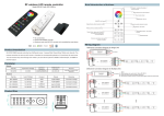
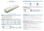
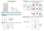
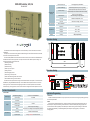
KNX LED Controller, 4CH, 5A
Button and red LED
SR-KNX9512FA
Green LED flashing
Indicate the application layer running normally
LEDs for Output
Indicate output status per channel, LED on mean the
channel has output, LED off mean the channel has not output.
Manual buttons
Switch via a short operation,
relative dimming via a long operation
OT. LED
Indicate over-temperature, >70 °C
OV. LED
Indicate over voltage, >40V DC
Operation and
display
For assigning the physical address
IP 20 , EN 60 529
Type of protection
Temperature
Ambient
Operation
-5 °C...+45°C
Storage
-25 °C...+55°C
Transport
-25 °C...+70°C
Humidity
<93%, except dewing
Dimension drawing
A
Prog.
B
C
D
A
B
C
D
156.0
23.0
166.0
Dimension drawing
KNX BUS+
KNX BUS-
Prog.
A
B
OV
C
KNX LED Controller
D
SIGNAL OUTPUT
SR-KNX9512FA
OT
N
100-230VAC
L
12-36VDC
Power Supply
12-36VDC
KNX BUS
The dimmer with LED constant voltage drive can drive LED directly, has four channels, each channel is
independent.
The output can connect with some big power dimmable LED lights. These LEDs can be switched, dimmed,
recall scene or other operations via the bus.
The devices adopt PUSH terminals to achieve electrical connection; the connection to the EIB/KNX bus is
established via a bus connecting terminal. The input need connect a 12V-36V DC operation voltage. The
following list provides a functional overview:
☆Switching the LED light
☆Relative dimming
☆Absolute dimming
☆Status report, error report
☆Setting 15 scenes
☆Staircase lighting function
☆Bus recovery (or reset) function
☆Preset value and modify preset value functions
☆Switch/relative dimming via manual buttons
The above function of parameters to configure and use are described in the chapter 5. The device has own
database file (.vd4) (SR-KNX9512FA/5A-4CH). There is added a manual operation function in the normal
dimming mode, it is invalid in the staircase lighting mode. Switch via a short operation of manual buttons,
relative dimming via a long operation, and in the case of the bus voltage fail the manual operation is invalid.
OV
53.4
OT
SIGNAL OUTPUT
ISO9001:2008
12-24VDC
KNX BUS
5
A
B
C
D
RGB/W LED strip
Technical characteristic
Application Programming
Technical data
Power supply
Bus Operating voltage
21-30V DC, via the KNX/EIB bus
Input voltage
12-36V DC
4 channels
Output
Connections
Rated current
5A×4CH
Load voltage
12-36V DC(constant voltage)
Safety
Short-circuit ,over voltage and over temperature protection
EIB/KNX
EIB bus connection terminal
Inputs/outputs
Using screwless connection terminal
Introduction
It is able to set different parameters to every output channel, and control various targets by modifying the setup
of the internal parameters.
Switch
The output can be switched ON or OFF by 1 bit data. It is able to set the brightness value as the last one or a
defined one (1%-100%) when switching on the luminaries. It is able to set a delay time (changing time) to dim
UP the luminaries or dim UP gradually in the default period. When receiving the OFF message, the dimmer will
be switched off immediately, or dim DOWN gradually after a delay time (changing time) or in the default
changing period.
Relative dimming
4 data bits control: the relative dimming command means it is possible to dim UP or DOWN to the needed
brightness value during the set brightness threshold range. It is only valid to dim UP when the brightness value
is smaller than the low threshold value and dim DOWN when the brightness value is greater than the high
threshold value. It is also able to set whether to switch on the luminaries by the message “dim UP to a certain
value” when the output is 0 by this function. The relative dimming is used to control the relative changes of the
brightness by 4 data bits: the lowest 3 bits are controlling-bit and the highest bit is----- “1” means dim UP, “0”
means dim DOWN.
Explanation of setting relative dimming: (1-7: dim DOWN; 0-8 remain unchanged (stop dimming); 9-15 dim
UP)
Parameter
0
1
2
3
4
5
6
7
Dim DOWN
Unchange/
stop dimming
255
128
64
32
16
8
4
Parameter
8
9
10
11
12
13
14
15
Dim UP
Unchange/
stop dimming
255
128
64
32
16
8
4
Reset
When the BUS is power off, all the outputs are switched off; the current brightness value will be saved to the
memory of the dimmer. When the BUS voltage is recovered, the brightness status may be the last brightness
value, or the preset brightness value.
When the BUS is power off, it may have the following situation occurring:
In the normal mode, 2 optional behaviors after the BUS voltage recovery are: the last brightness value before
power off, or the set value.
In the staircase lighting mode, the behavior after the BUS voltage recovery is: ON or OFF. No output when it
is OFF; start the behavior “switch=1” when it is ON.
Safety & Warnings
1) The product shall be installed and serviced by a qualified person.
2) IP20.Please avoid the sun and rain. When installed outdoors, please ensure it is mounted in a water proof
enclosure.
3) Always be sure to mount this unit in an area with proper ventilation to avoid overheating.
4) Please check if the output voltage of any LED power supplies used comply with the working voltage of the
product.
5) Never connect any cables while power is on and always assure correct connections to avoid short circuits
Absolute dimming
8 data bits control: it is able to dim to the needed brightness value by changing the brightness parameters.
The setting of the parameters is similar as relative dimming with the brightness value range: one low threshold
value and one high threshold value. And it is not allowed to change the brightness value beyond the set range,
the max. range is from 0 to 255. This function offers the possibility to dim UP or DOWN to 0 gradually to the
target value by setting the delay time or the default time.
The high and low threshold value limits the total output of the dimmer; any brightness value beyond the range
is not valid.
When the output is 0, it is able to set switching off the luminaries or remaining to a lower brightness value;
and also in this status it is optional to switch on the luminaries by receiving the message “absolute dimming”.
Status Report
1 data bit: the dimmer offers the possibility whether sending the latest brightness value report of the
controlled target and the changed report of the switch status to the BUS.
Scene
8 data bits control: the dimmer offers 15 (1-15) scenes for selection. It is possible to set ONE brightness
value and the gradual change time of ON for each scene. After setting, it is easy to call any favorite scene. 1 in
the highest bit of the scene command it means “saving” command, to save the current brightness value to the
relevant scene.
Preset Value
The dimmer can preset scene, the object directly through 1bit data to transfer the preset scene or through
1bit data to let favorite scene to replace original preset scene. There are two preset values per output, there are
two brightness values can be transfer for each preset value. Such as in theater, we need a relatively bright
lighting effect when coming in, we can through transfer the first brightness value to be achieved this effect,
when the movie starts playing, we need a relatively dark lighting effect, we can through transfer the second
brightness value to be achieved. We can return to the previous brightness value when the movie ended.
Staircase Lighting Function
The dimmer offers the function of staircase lighting control besides the normal lighting control.
The staircase lighting function serves to switch off the lighting directly until dimming DOWN to 20% of the
brightness value after a set period. It is able to set the brightness of the luminaries, the duration of the light ON,
the time to dim down to 20% separately.
In this function, it uses 1 data bit control the targets directly by setting a permanent fixed value to the output
of the staircase luminaries.
The steps of staircase lighting control: the staircase luminaries will be switched on for a certain time (this
time can be set) if the controlled target receives the message of “1”; these luminaries will be switched on again
when receiving another message “1” during this period. The luminaries will be switched off when they are
dimmed down to 20% of the brightness value (the dim down time can be set) after this period, or switch off the
luminaries by sending message “0” to the controlled target. The luminaries will be off after dimming down to
20% when receiving the message “0” (the same dimming down time as above). When enabling the function “On
reception switch OBJ=0 switch off”, it is able to use the function "switch off" to turn off the output in the status of
"permanent on", or change the status from "switch on" to "permanent on" (message “1” means ON, “0” means
OFF).
before switching on.
6) Please ensure that the cable is secured tightly in the connector
7) For update information please consult your supplier.
Warranty Agreement
1) We provide lifelong technical assistance with this product:
5-year warranty. We print date on every products, for example :1125 means year 2011,week 25.The
warranty is for free repair or replacement and covers manufacturing faults only.
For faults beyond the 3-year warranty we reserve the right to charge for time and parts.
2) Limited Warrenty
Any defects caused by wrong operation.
Any damages caused by unauthorized removal, maintenance, modifying, incorrect connection and
replacement of chips.
Any damages due to transportation, vibration etc. after purchase.
Any damages caused by earthquake, fire, lightning, pollution and abnormal voltage.
Any damages caused by negligence, inappropriate storing at high temperatures and humidity or near
harmful chemicals.
Product has been updated
3) Repair or replacement as provided under this warranty is the exclusive remedy to the customer.