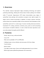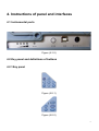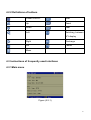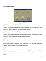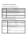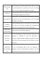
1
DIT330
Optical Fiber Fusion Splicer
Optical Fiber Fusion Splicer
-------User’s Manual------
1
Contents
1. Overview ......................................................................................................................... 7 2. Features .......................................................................................................................... 7 3. Specifications ................................................................................................................. 8 4. Instructions of panel and interfaces ............................................................................ 9 4.1 Instrumental ports................................................................................................ 9 4.2 Key panel and definitions of buttons ................................................................ 9 4.2.1Key panel.................................................................................................... 9 4.2.2 Definitions of buttons ............................................................................. 10 4.3 Instructions of frequently used interfaces ...................................................... 10 4.3.1Main menu................................................................................................ 10 4.3.2 Menu options .......................................................................................... 11 5. Guide to software operations ..................................................................................... 12 5.1 Power ON/OFF .................................................................................................. 12 5.2 LCD brightness .................................................................................................. 12 5.3 Time setup .......................................................................................................... 12 5.4 Operations of splicing parameter files............................................................ 13 5.4.1 Select ....................................................................................................... 13 5.4.2 View, modify............................................................................................ 14 5.4.3 Copy from the system ........................................................................... 15 5.4.4 Reset system default settings .............................................................. 16 5.5 Operations of heating parameter files ............................................................ 17 2
5.5.1 Select ....................................................................................................... 17 5.5.2 View, modify............................................................................................ 18 5.5.3 Copy from system .................................................................................. 19 5.5.4 Reset system default settings .............................................................. 20 5.6 Save splicing results ......................................................................................... 20 5.6.1 Enter the list of splicing recording files: .............................................. 20 5.6.1 View, delete, clean history splicing records ....................................... 21 5.7 Electrode discharge times................................................................................ 22 5.7.1 View, clean Electrode discharge times ............................................... 22 6. Operations of splicing ................................................................................................. 24 6.1 Install optical-fiber heat shrinkable tube ........................................................ 24 6.2 Cleaving and cleaning of optical fibers .......................................................... 24 6.3 Cleave optical fober .......................................................................................... 25 6.4 Place optical-fiber .............................................................................................. 26 6.5 Splicing................................................................................................................ 27 6.5.1 Select splicing parameter files, heating parameter files .................. 27 6.5.2 Start splicing ........................................................................................... 28 7. Operations of heating.................................................................................................. 31 8. Discharge and calibration ........................................................................................... 32 9. Instructions of parameters.......................................................................................... 34 9.1 Descriptions of splicing global parameters.................................................... 34 9.2 Descriptions of splicing parameters ............................................................... 34 3
10. Part list ........................................................................................................................ 37 11.Troubleshooting ....................................................................................................... 38 11.1 Power supply ................................................................................................... 38 11.2Operations of splicing ...................................................................................... 38 11.3 Operations of heating ..................................................................................... 39 12. Maintenance ............................................................................................................... 41 12.1 Clean V-groove................................................................................................ 41 12.2 Clean fiber presser foot .................................................................................. 41 12.3 Clean air-tight lens .......................................................................................... 42 12.4 Clean objective lens........................................................................................ 42 12.5 Regular inspection and cleaning .................................................................. 42 12.6 Maintenance of cleavers ................................................................................ 43 Appendix A: Warranty ..................................................................................................... 45 4
Warnings (ignoring the warnings or improperly operating the fusion splicer
may result in serious injuries or death).
The input voltage of the machine must be within the specified range, please
prevent the input voltage exceeding the range. Please use proper AC, DC power
supply.
When any of the following faults occurs, please immediately pull AC power cord
out of the receptacle and turn off the fusion splicer, otherwise the machine may
become irreparable even result in injuries, death and fire.
Smoke emits out, order smells, noise sounds or heating appears abnormal, or
Liquid, foreign object falls inside the machine, or
Machine is damaged or crashed.
No parts of the machine needs maintenance, please don’t disassemble the
machine or modules of power supply. Any improper repair or maintenance may
make the machine irreparable or result in injuries.
The machine must use the power modules that the manufacturer specified.
In order to avoid fire, explosion or any other material consequence, don’t use the
machine in any place where there is flammable gas or liquid.
Precautions:
This machine is used to splice glass optical fiber, please don’t use it for any other
purpose. Please read this Manual thoroughly before using the machine.
5
Please don’t store the machine in high-temperature or high-humidity environment.
If the machine is used in dusty environment, please take all possible measures to
prevent the dust falling to the machine.
When the machine is moved from a low-temperature environment to a
high-temperature environment, please try to make the machine experience a
transition from the low temperature to high temperature so as to dispel the
condensation.
To keep the machine in good performance, users are recommended to make
maintenance for entire machine at least once a year.
The machine has been precisely calibrated, please try to prevent strong shake or
collision, please transport and store it using special carton.
Any repair or commissioning of the machine is to be made by technicians. If you
find any problem, please immediately contact the manufacturer.
6
1. Overview
The machine employs high-speed image processing technology and special
positioning technology, allowing the total process of fusion splicing to be finished
within 10 seconds. Large-screen LCD clearly demonstrates every stage of
optical-fiber fusion splicing. As the machine is compact in size, light in weight, it is
ideal to work in outdoor environment. In addition, it is easy to operate, fuses fast,
with low fusion loss, especially suitable for the construction and maintenance of the
optical-fiber works built in a wide range of sectors including telecommunications,
broadcast & TV, railway, petrochem, electricity, army, police, as well as teaching
and research of scientific institutes. In order to finish the fusion operations more
accurately, please thoroughly read this Manual.
2. Features
Handy, easy-to-carry, solid and durable
Color LCD
Data can be uploaded to PC via USB cable
Intelligent power volume indicator and auto power-off at low voltage
Visual interface
Built-in heater
It provides a wide range of fusion and heating parameters for your choice.
Built-in light (make optical-fiber placement more convenient)
7
3. Specifications
Applications
SM(single-mode), MM(Multi-mode), DS(Dispersion displacement),
NZDS(Non-zero dispersion displacement)
Splice loss
0.02dB(SM), 0.01dB(MM), 0.04dB(DS), 0.04dB(NZDS)
Return loss
Greater than 60dB
Operation mode
Full auto, semi-auto, manual
Average splicing time
10s
Average heating time
36s
Fiber aligning method
Core aligning, clad aligning
Fiber diameter
Cladding diameter:80 ~150µm , Coating diameter:100 ~1000µm
Fiber cleaved length
10~16mm(coating diameter:<250µm) ; 16mm(coating diameter: 250~
1000µm)
Lens magnification
Vertical double display: 310x; horizontal double display, 155x
Display
High-definition 5.1” 640*480 LCD provides fine and clear images
Tension test
Standard 2N(optional)
Heat shrinkable tube
60mm, 40mm and a series heat shrinkable tube
Battery capacity
Typical: 250 times of splice, it takes 3.0 hours to fully charge it (the machine is
operable during charging process)
Battery life
300~500 charging cycles
Power volume display
Real-time power volume display in the screen
Electrode life
Typical 5000times, customer can change electrode by himself
Optical-fiber clamp
New design allows optical-fiber positioning to be easier and more accurately.
Construction lighting
Built-in high-brightness, wide-range light substantially increases easiness of
construction at night.
External ports
Standard USB port
Power supply
Built-in 11.8V lithium battery; external adapter, input: AC100-240V, output:
DC12.6V/5.0A
Operating conditions
temperature: -10 ~+50 ; humidity: 95%RH(40 , no condensation); height:
0~5000m above sea level
Dimensions
Length×Width×Height=169×152×155(mm)
Weight
2.4kg(exclusive of battery), 2.9kg(inclusive of battery)
8
4. Instructions of panel and interfaces
4.1 Instrumental ports
Figure (4-1-2)
4.2 Key panel and definitions of buttons
4.2.1Key panel
Figure (4-2-1)
Figure (4-2-2)
9
4.2.2 Definitions of buttons
Power ON/OFF
Start
Up
Reset
Down
Heat
Left
Switching between
X/Y display
Right
Discharge
OK
Cancel
Menu
4.3 Instructions of frequently used interfaces
4.3.1Main menu
Figure (4-3-1)
10
4.3.2 Menu options
Figure (4-3-2)
(1) Splicing parameters (SplicePara)
It lists all the Splicing parameter files already configured well. User can select, view,
modify the Splicing parameter file under this menu option.
(2) Heating parameters (HeatPara)
It lists all the heating parameter files already configured well. User can select, view,
modify the heating parameter file under this menu option.
(3) System setup (SysSetup)
Under this menu option, user can realize the functions such as time setup,
power-saving set-up, resetting. More importantly, total splicing parameters
(splicing control) are also set under this menu option.
(4) History
All splicing results are saved in the interface of splicing data under this option in
form of data file. Besides, user can view electrode discharge times under this
option.
11
5. Guide to software operations
5.1 Power ON/OFF
Power ON:
Press and hold
for 1 second or so, the LED indicator on control panel will
illuminate, company LOGO will appear in the screen.
Normal soft power-off:
Normal soft power-off ensure no data loss will occur after power-off, user just need
click
, the machine will be powered off in normal soft mode.
Forced power-off:
Press and hold
for 5 seconds or so, the machine will be immediately turned
off, in such case, the data will be lost. Forced power-off mode is usually chosen
when the instrument appears abnormal and normal soft power-off fails.
5.2 LCD brightness
While in main menu, click
to increase LCD brightness, click
to
decrease LCD brightness. While in this interface, user can realize the functions by
operating status bar.
5.3 Time setup
There is an option “Time Setup” as shown in the figure below under the sub-menu
“SysSetup”:
12
Figure (5-3-1)
5.4 Operations of splicing parameter files
5.4.1 Select
(1) Enter the interface of list of splicing parameter files as shown in Figure (5-4-1):
Figure (5-4-1)
(2) Click
to move the cursor, choose and highlight the parameter
files to be operated.
(3) Click
to popup the sub-menu as shown in Figure (5-4-2):
13
Figure (5-4-2)
(4) Choose the option “Select””. The moment the currently highlighted files will be
chosen as current splicing parameter file. The moment current splicing parameter
file will be marked with a tick “√” in the left as shown in Figure (5-4-3) below.
Figure (5-4-3)
5.4.2 View, modify
(1) Enter the list of splicing parameter files as shown in above Figure (5-4-1).
(2) Click
to move the cursor, choose and highlight the parameter
files to be viewed or modified.
14
(3) Click
to popup the sub-menu, choose the option “Modify”. The moment
the system will enter the interface of Edit splicing parameter files as shown in
Figure below.
Figure (5-4-4)
5.4.3 Copy from the system
Using this option, the selected system splicing parameter files can be copied to
defined user splicing parameter files.
(1) Enter the list of splicing parameter files as shown in above Figure (5-4-1).
(2) Click
to move the cursor, choose and highlight the parameter
files to be modified.
(3) Click
to popup the sub-menu, select the option “Copy from system”. The
moment the system will enter the interface of system splicing parameter files
as
shown in Figure below.
15
Figure (5-4-5)
(4) Click
to move the cursor, choose and highlight the system
splicing parameter files from which the files are copied.
(5) Click
to copy files..
5.4.4 Reset system default settings
Using this option, all the user splicing parameter files will be reset to factory default
settings.
(1) Enter list of splicing parameter files as shown in above Figure (5-4-1).
(2) Click
to popup the sub-menu, select the option “All reset”. The moment a
dialog box as shown in Figure below will pop asking you whether to reset default
settings.
16
Figure (5-4-6)
(3) Click
to confirm “All reset”, Click
to cancel the operation.
5.5 Operations of heating parameter files
5.5.1 Select
(1) Enter the list of heating parameter files as shown in Figure below:
Figure (5-5-1)
(2) Click
to move the cursor, choose and highlight the parameter
files to be operated.
(3) Click
to popup the sub-menu as shown in Figure below:
17
Figure (5-5-2)
(4) Choose the option “Select””. The moment the currently highlighted files will be
chosen as current heating parameter files. Current heating parameter files will be
marked with a tick “√” in the left as shown in Figure below:
Figure (5-5-3)
5.5.2 View, modify
(1) Enter the list of heating parameter files as shown in above Figure (5-5-1).
(2) Click
to move the cursor, choose and highlight the parameter
files to be viewed or modified.
18
(3) Click
to popup the sub-menu, choose the option “Modify”. The moment
the system will enter the interface of Edit heating parameter files.
5.5.3 Copy from system
Using this option, the selected system heating parameter files can be copied to
defined user heating parameter files.
(1) Enter the list of heating parameter files as shown in above Figure (5-5-1).
(2) Click
to move the cursor, choose and highlight the parameter
files to be modified.
(3) Click
to popup the sub-menu, select the option “Copy from system”. The
moment the system will enter the interface of system heating parameter files as
shown in Figure below:
Figure (5-5-5)
(4) Click
to move the cursor,, choose and highlight the system
heating parameter files from which the files are copied.
(5) Click
to copy files..
19
5.5.4 Reset system default settings
Using this option, all the user heating parameter files will be reset to factory default
settings.
(1) Enter the list of heating parameter files as shown in above Figure (5-5-1).
(2) Click
to popup the sub-menu, select the option “All reset”. the moment a
dialog box as shown in Figure below will popup asking you whether to reset the
default settings:
Figure (5-5-6)
(3) Click
to confirm “All reset”, Click
to cancel the operation.
5.6 Save splicing results
The results of splicing operations will be automatically saved in form of splicing
recording file. This operation can be made in the interface “Splicing data”.
5.6.1 Enter the list of splicing recording files:
(1) Enter the menu option “History” as shown in Figure below:
20
Figure (5-6-1)
(2) Select splicing data, click
to enter the list of splicing recording files as
shown in Figure below:
Figure (5-6-2)
5.6.1 View, delete, clean history splicing records
(1) First enter the list of splicing recording files, for operating steps please refer to
Section 5.6.1.
(2) Click
to move the cursor, choose and highlight the splicing
recording file to be operated.
21
(3) Click
to popup the sub-menu, select the option “view ”, the system will
enter the interface of splicing recording files, and display the contents of splicing
records as shown in Figure (5-6-3) below; select “delete ” to delete current splicing
record; select “clean ” to clean all splicing records.
Figure (5-6-3)
5.7 Electrode discharge times
5.7.1 View, clean Electrode discharge times
(1) Enter the menu option “History” as shown in above Figure (5-6-1).
(2) Then enter the interface of electrode data to view current Electrode discharge
times. The interface is as shown in figure below:
22
Figure (5-7-1)
(3) Click
to popup the sub-menu, select the option “Zero” to zero current
Electrode discharge times.
23
6. Operations of splicing
6.1 Install optical-fiber heat shrinkable tube
Install optical-fiber heat shrinkable tube onto the optical-fiber
6.2 Cleaving and cleaning of optical fibers
Cleave the clad of optical fibers by 30-40mm using cleaver, then clean the optical
fiber using yarn or soft cotton paper dipped with alcohol. Then wipe it once using
clean cotton cloth, don’t wipe it for a second time using the same cotton cloth.
Stripping
24
Cleaning
Caution: please use the alcohol of higher than 99%.
6.3 Cleave optical fober
(1) First make sure the sliding board installed with knives in the frontal end, then
open big and small pressing board.
(2) Align the cladding edge of optical-fiber to appropriate scale of the gauge, then
place the optical-fiber into guide groove, make sure the stripped optical fiber is
straightly placed on rubber pad.
(3) Close the small pressing board and integrated pressing board, push the slide
with knives to the other side, so as to cut off the optical-fiber.
(4) Open the integrated pressing board, while holding the optical-fiber with hands
and opening small pressing board concurrently, remove the shredded optical fiber
25
with fingers, move away the optical-fiber carefully, note prevent the section of
optical-fiber contacting anything else.
6.4 Place optical-fiber
(1) Open storm shutter and pressing board.
(2) Place the ready optical fiber on V-groove, with the tip lying between the tip of
electrode and the edge of V-groove. If the optical-fiber is bend, keep the bending
part upward when you place the optical fiber. Please prevent the ready optical-fiber
colliding with anything so as to ensure the quality of optical ends.
(4) Hold the optical-fiber with fingers, then close the pressing board and press the
optical fiber. Make sure the optical fiber is placed at the bottom of V-groove. If the
optical-fiber has been improperly placed, please place it again.
(4) Place another optical-fiber following the above procedures.
26
(5) Close storm shutter.
6.5 Splicing
6.5.1 Select splicing parameter files, heating parameter files
Select splicing parameter files:
(1) Enter main menu, select the option “splicing parameters”, then enter the list of
splicing parameter files as shown in Figure (5-4-1).
(2) Click
to move the cursor, choose and highlight the parameter
files to be operated.
(3) Click
to popup the sub-menu as shown in Figure (5-4-2). Choose the
option “Select””. The moment the currently highlighted files will be chosen as
current splicing parameter file. Current splicing parameter file will be marked with a
tick “√” in the left as shown in Figure (5-4-3) below.
Select heating parameter files:
(1) Enter the list of heating parameter files as shown in Figure (5-5-1).
(2) Click
to move the cursor, choose and highlight the parameter
files to be operated.
(3) Click
to popup the sub-menu as shown in Figure (5-5-2) below, Choose
the option “Select””. The moment the currently highlighted files will be chosen as
current heating parameter files. current
heating parameter files will be marked
with a tick “√” in the left as shown in Figure (5-5-3).
27
6.5.2 Start splicing
Pause 2
(1) After optical-fiber is placed in the splicer, Click
to start splicing. After
cleaning and discharging, the optical-fiber will stop at the preset position. Next,
check the cleaving angle of optical-fiber and quality of optical-fiber end. If the
measured cleaving angle is bigger than the preset limit value, or spurs are found in
the end of optical-fiber, the buzzer will alarm, concurrently an error message will
appear in the display alerting the operator. In the meantime, the splicing will pause.
Even though there are no error message alerting the operator, the operator should
inspect the end of optical-fiber manually. If any phenomenon as described below is
found, take the optical-fiber out of the splicer, then get the optical-fiber again. Any
defect on the surface of optical-fiber may lead to splicing failure, and the quality of
optical-fiber end exerts material impact on the loss of joint, therefore, please try to
make the optical-fiber end appear in a plane, and the angle between such a plane
and section of optical-fiber shall be less than 1°.. for example, the optical-fiber
end as shown in Figure (a) below is good for splicing, but the ends shown in
28
Figures (b)~ (f) are defective, user should remake ends for these optical fiber. After
inspecting the optical-fiber, align it in core-to-core or clad-to-clad manner, axial
offset will appear.
(a) Good end:
(b) Unfilled corner:
(c) Extruding tip:
(d) Tooth:
(e) Concave:
(f) Turtle pattern:
(2) After aligning is over, the machine will discharge and splice the optical-fiber.
Splicing finished
(3) After splicing is finished, the estimated splice loss will appear. The calculation
of splice loss is based on some spatial parameters. When either of splice loss or
cleaving angle exceed its preset limit value, the machine will display an error
29
message. If inspection shows that any spliced optical-fiber has anything abnormal,
e.g.: too thick, too thin, or bubble, the splicer will display an error message. Even
though there are no error messages displayed, but the splicing results are found
very bad in the display, we recommend users to remake the splicing.
Caution
a. Sometimes the splicing point may look a little thicker than other parts, but the
splicing result will still be considered normal, and it doesn’t impact the splice loss.
b. To change the cleaving angle of optical-fiber and calculate limit values of splice
loss, please refer to the section [splicing mode].
c. Error messages, e.g.: “calculate splice loss”, “splicing angle”, “too thick”, “too
thin”, “bubble” can be ignored. User can set these functions as “disabled”.
d. In some cases, extra discharge may improve splice loss. Click
to make
extra discharge, the moment, the splice loss will be recalculated, and the
optical-fiber will be reinspected.
30
7. Operations of heating
(1) Open the cover of heater
(2) Open storm shutter, with left hand holding left side of optical-fiber at the edge of
storm shutter.
(3) Open left pressing board, hold optical-fiber firmly till total optical fiber is moved
into heater.
Heating
(4) Open the right pressing board.
(5) Hold the right part of optical-fiber with right hand, take down the spliced optical
fiber from the machine and place it into the right pressing board.
(6) Set the splicing point at the central position of heating protective tube using
heat shrinkable tube central positioning device.
(7) Close the left and right pressing boards and the cover of heater.
(8) Click
to start heating. When heating is finished, buzzer will alarm
(9) Open the cover of heater and take away the optical fiber under the protection
of heat shrinkable tube. Some pull is to be exerted when the optical fiber is taken
out from the heater. The moment heat shrinkable tube may have bonded with the
bottom board of the heater, if so, take out the heat shrinkable tube using cotton
swab.
(10) After heating is over, check heat shrinkable tube whether there are bubbles or
dust inside it.
31
8. Discharge and calibration
The atmospheric environment such as temperature, humidity, air pressure is
always changing, as a result, the discharging temperature is always charging.
Temperature and air pressure inductors have been built in the machine, they can
feedback the environmental parameters to control system, so as to adjust
discharging strength.
As the change of discharging strength arising of electrode abrasion and
optical-fiber shred adhesion can’t be corrected automatically, and sometimes the
discharging central position may move leftward or rightward. For this reason, the
splicing position of optical-fiber may offset against discharging centre, to solve this
problem, a discharging calibration is to be made. Using this function, current
discharging strength is measured and corrected as standard strength, and
discharging strength is to be inspected based on the axial offset of splicing part
before and after discharging. Discharge calibration will change the parameter
value of discharging strength, this value will be applied in all splicing processes.
Operating procedures
(1) Enter main menu, select the option “ArcCalib”, open the picture of discharging
and calibration.
(2) Prepare optical-fiber and place it in the splicer.
(3) Discharge the optical-fiber before pushing it in, so as to test the discharging
central position, and set the interval centre of optical-fiber at the discharging
32
central position.
(4) An axial offset is intentionally for the optical-fiber while the discharging and
calibration are made.
The calibration results will appear in the screen when discharging and calibration
are finished.
(5) Discharging strength and splicing position have been calibrated, but we still
strongly recommend to make further calibration.
33
9. Instructions of parameters
9.1 Descriptions of splicing global parameters
Parameters
Descriptions
Pause 1
For observing the cutting conditions of ends
Pause 2
For observing the aligning conditions of ends
Tensile
For improving splicing strength of optical-fiber
splicing
Tensile test is to be made after splicing is over to observe the
Tensile test
splicing conditions of optical-fiber
9.2 Descriptions of splicing parameters
Parameters
Descriptions
There are four types of optical-fibers, i.e.: SM(Single-mode),
Type of
MM(Multi-mode),
DS(Dispersion
displacement),
optical-fibers
NZDS(Non-zero dispersion displacement).
Set optical-fiber aligning modes
“Core
Aligning
aligning”:
align
optical-fiber
through
core
of
optical-fiber
“Clad aligning”: align optical-fiber through central position of
clad.
34
Set limit values of cleaving angle. When either of the left
Cleaving angle
and right optical fiber exceeds the limit value of cleaving
limit
angle, an error message will appear in the screen.
When estimated splice loss exceeds the preset loss limit, an
Loss limit
error message will appear in the screen.
When either of the two optical-fibers exceeds limit values of
Core angle limit the preset limit value of bending angle, an error message
will appear in the screen.
Cleaning discharge lasts for a short while. It is used to clean
Cleaning
micro dust on the surface of optical fiber. Changing this
discharge time
parameter will change length of cleaning discharge.
Optical-fiber
Set the interval of optical-fiber alignment.
interval setting
Set the pre-discharge strength during the period from the
Optical-fiber
beginning of discharge to when the optical-fiber is
pre-fusion
pushed-in. If [pre-discharge strength] is too great, the end of
strength
optical-fiber will fuse excessively, this will lead to too much
splice loss.
Optical-fiber
Set the pre-discharge period from the beginning of
pre-discharge
discharge to when the optical-fiber is pushed-in. Too long
time
[pre-discharge time] will bring the same results as that of too
35
great [pre-discharge strength].
Pushed-in
The pushed-in length of optical fiber after pre-fusion.
length
Discharge proceeds in two stages. The first discharge
Strength of
strength is called stage 1 of discharge. Here user can set
discharge 1
the strength of discharge 1.
Time of
Set the time of discharge 1.
discharge 1
Strength of
Discharge 2 is stage 2 of discharge. Here user can set the
discharge 2
strength of discharge 2.
Time of
Set the time of discharge 2.
discharge 2
Tensile
The discharge strength during tensile splicing.
discharge
strength
Tensile
The discharge time during tensile splicing.
discharge time
Tensile degree
The tensile splicing degree
Tensile waiting
The waiting time before tensile splicing is started
time
Discharge
To optimize discharge strength so as to adapt the core bias.
strength
There are the following compensation modes: auto, manual,
36
compensation
close compensation
mode
Discharge
The amount of compensation
strength
compensation
value
10. Part list
No.
1
2
3
4
DESCRIPTION
Fusion Splicer
Battery
USB charger
Optical Fiber Cleaver
QUANTITY
1
1
1
1
5
6
7
8
9
10
11
Fiber Optic Cable Stripper
Stainless steel tweezers
Spare electrode
Cooling tray
Cotton swab
Alcohol bottle
Fiber Holder(RY-F600H)
1
1
2
1
1
1
1
37
11.Troubleshooting
11.1 Power supply
Fully charged battery can’t support splicing for more than one time.
If power-saving function is disabled, power consumption will rise.
As the battery’s discharge depends on medical reaction, if temperature is too low
especially falls below 00C, the volume may decline.
While in high-altitude regions, the discharge current will rise. Under such
conditions, current will decline faster.
AC adapter can’t charge the battery properly.
Power volume display is incorrect
The information appearing in the power volume indicator is for reference only.
Power volume indicator doesn’t work well.
11.2Operations of splicing
Splice loss is unsteady/too high
Clean V-groove, optical-fiber clamps, reflector, objective lens in storm shuttle.
If the optical-fiber with secondary protective layer has bending or curling memory,
please keep the bending part upward when placing the optical-fiber.
38
If the splice loss still appears too high or unsteady after taking the above actions,
please contact the dealer. Users are recommended to make maintenance regularly
for the machine (at least once a year) so as to ensure good splicing quality.
How to resume parameters of discharge conditions
Please refer to Section select splicing parameter files]
Change limit values of cleaving angle, splice loss, offset angle
Please refer to Section [view, edit splicing parameter files]
Ignorable error messages
Please refer to [Splicing control] under the option History, error message is
permitted to be ignored.
Display cleaving angle, optical-fiber angle, core/clad bias
Please refer to [Splicing control] under the option History.
Estimated value of splice loss differs from the actual value
Estimated value of splice loss is just a calculation result, it is provided for reference
only.
The optical parts of splicer needs cleaning.
11.3 Operations of heating
Heat-shrinkable tube doesn’t shrink completely
Extend the heating time. For details please refer to Section [View , edit
heating
parameter files]
39
Heat indicator on control panel blinks
Click
while in heating process, the Heat indicator may blink, click
again, heating operation will be cancelled.
If the temperature doesn’t reach the presser value, the indicator will blink and
alarm sounds at the same time, if so, please contact the dealer.
Heat-shrinkable tube bonds with heating board after it shrinks.
Separate them using cotton swab or soft things.
Initialize heating conditions
Please refer to Section [View , edit
heating parameter files]
Cancel heating
Click
, the system doesn’t respond, the moment you need to click
.
40
12. Maintenance
12.1 Clean V-groove
If there is any contaminant in V-groove, it will be unable to clamp optical-fiber, this
will increase splice loss. Therefore, please regularly inspect and clean V-groove at
fixed intervals. V-groove cleaning steps:
(1) Open storm shuttle
(2) Clean the bottom of V-groove with cotton swab dipped with alcohol, and
remove the alcohol left in V-groove with dry cotton swab.
Please note to avoid using too strong force when cleaning V-groove, so as to
prevent any damage to walls of V-groove. If the cotton swab dipped with alcohol
can’t clean the contaminant from V-groove, please use the tail of an optical-fiber
which is cut well to remove the contaminant. Afterwards repeat step 2.
12.2 Clean fiber presser foot
If there is dust on presser foot of optical-fiber, the optical-fiber may not work well,
this may result in poor splicing quality. Therefore, please regularly inspect and
clean the presser foot of optical-fiber at fixed intervals. Presser foot cleaning steps:
Open storm shutter
Clean the surface of presser foot with thin cotton swab dipped with alcohol, then
wipe dry the presser foot with dry cotton swab.
41
12.3 Clean air-tight lens
If air-tight lens get dirty, the optical-fiber core may be difficult to keep in correct
position because the transparency degrades, this will surely results in high loss. It
can be cleaned in the following steps: clean the surface of air-tight lens with thin
cotton swab dipped with alcohol, then remove the residual alcohol on air-tight lens
with dry cotton swab. If the lens are clean, they will be free of stripe pattern or dirt.
12.4 Clean objective lens
If objective lens get dirty, it may affect good observation over the position of
optical-fiber core, this will result in high splice loss or poor splicing quality.
Therefore, please regularly clean the two objective lens at fixed intervals,
otherwise more and more dust will stay on the lens and it will be harder to remove
them. Objective lens cleaning steps:
(1) Please shut off the power before cleaning objective lens.
(2) Clean the objective lens in circling action from centre to edge using thin cotton
swab dipped with alcohol, then remove the residual alcohol with dry cotton swab.
Please note to first remove electrode bar before cleaning objective lens, and note
to avoid colliding with or touching electrode bar in cleaning process. The surface of
objective lens should keep clean and free of dirt.
12.5 Regular inspection and cleaning
To keep good splicing quality, users are recommended to perform regular
42
inspection and cleaning at fixed intervals.
12.6 Maintenance of cleavers
(1) Rotate blade of cleaver
If cleaver can’t cut off optical-fiber, rotate the blade by 1/16 of a round, so as to
keep the blade sharp as a new one. Blade rotating steps:
Remove the pressing pad distance limit device. Unfasten screws using screwdriver,
rotate the blade by 1/16.
While you are rotating the blade, please note to avoid touching the edge of knife.
Using thin cotton swab to rotate blade may be safer.
(2) Adjustment of blade height
If a round blade has been rotated by a round (it means that the 16 sides of the knife
have all been used), user need to adjust the blade height to compensate the
abrasion of blade. Adjustment steps:
Unfasten blade locking screws, adjust the locking screws using a 0.89mm hexagon
wrench.
Adjust the adjustment screw clockwise using a 1.5mm hexagon wrench to marked
point and align it with next position mark. Please don’t rotate screw over two marks
at one time. Fasten the adjustment screw. Fasten blade locking screw.
(3) Change of blade
If a blade has been raised for 3 times, you should change the blade .
43
44
Appendix A: Warranty
Warranty term and warranty conditions
We provide free repair for any fault occurring within 1 year since the date of
delivery, except:
Any fault or damage caused by natural disasters.
Any fault or damage caused by abnormal voltage of power supply.
Any fault or damage arising of improper operations.
Any fault or damage arising of violating against operating procedures or
instructions as described in the User’s Manual.
Please contact the dealer before sending the machine to us for repair.
To request for repair, please provide the following information:
Your full name, occupation, company name, address, phone number, fax, e-mail.
Machine model and SN
Fault description
Background and time of the fault occurrence.
Status quo of machine
Display status and relevant error messages, etc.
45