1
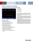
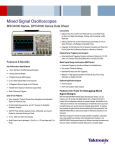
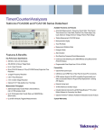
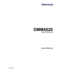
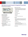
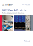
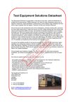
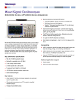
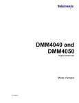
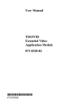
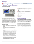
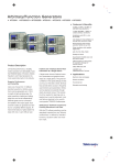
Digital Multimeters
Tektronix DMM4020 Data Sheet
Available Functions and Features
Volts, Ohms, and Amps Measurements
True RMS (AC, AC + DC) Measurements
Diode and Continuity Testing
Frequency Measurements
2×4 Ohms 4-wire Measurement Technique
Dedicated DC Leakage Current Measurements
Six Dedicated Buttons for Fast Access to Instrument Setups
DMM4020
Features & Benefits
Key Performance Specifications
Limit Compare Mode for Pass/Fail Testing
Connectivity
Front 2×4 Measurement Inputs
5.5 Digit Resolution
RS-232 on Rear Panel for Quick PC Connectivity
Basic VDC Accuracy of up to 0.015% (1 yr.)
Includes USB to RS-232 Interface Adapter Cable
200 mV to 1000 V Voltage Range, with up to 1 μV Resolution
200 μA to 10 A Current Range, with up to 1 nA Resolution
Includes National Instrument’s LabVIEW SignalExpress™ TE Limited
Edition for Connecting Your Bench
200 Ω to 100 MΩ Range, with up to 1 mΩ Resolution
CAT I 1000 V, CAT II 600 V
3-year Warranty
Data Sheet
Measurements with the Push of a Button
As the circuits in embedded system designs become more sophisticated,
you must measure a multitude of different parameters to validate your
design. The Tektronix DMM4020 5.5 digit bench multimeter offers a broad
range of functions in one easy-to-use instrument.
Typical multimeter measurements – volts, ohms, and amps – are made with
a basic VDC accuracy of up to 0.015%, ensuring you have the performance
you need for your design. You can also use the DMM4020 to measure
frequency, and to perform continuity and diode tests. This allows you
to replace your counter, continuity tester, and DMM with one versatile
instrument, saving bench space and cost.
Measure Nanoampere Signals
Measuring standby current in today’s energy-efficient designs requires
looking at very low currents, often in the microamp or nanoamp range.
Using a traditional multimeter for this measurement can lead to inaccurate
results since they typically employ the shunt resistance technique for
measuring current.
The DMM4020 offers an improved method for measuring low currents. By
using a current-to-voltage op amp technique, the DMM4020 can make
current measurements with 1 nA of resolution and with minimal loading
affect on the circuit under test, giving results that reflect real-world operation
of the device.
Designed to Make Your Work Easier
The DMM4020 multimeter is designed with the ease of use and familiar
operation you expect from Tektronix.
Intuitive Operation
Dedicated front-panel buttons provide fast access to frequently used
functions and parameters, reducing setup time. You no longer need to
search through software menus to find the function you need.
2
www.tektronix.com/dmm
Limit compare mode on the DMM4020.
Setup Buttons for Your Common Measurements
With six setup buttons on the front panel, you can save the settings for your
most common measurements. Simply set up the meter for a measurement,
then press shift followed by a setup button to save the measurement
settings. Now each time you perform that measurement, you simply press
the appropriate setup key.
Dual Display
With the unique dual display, you can measure two different parameters of
the same signal from one test connection.
Limit Compare
The limit compare mode provides pass/fail indicators to quickly show if a
test passes or fails to help eliminate mistakes, especially for results that
are close to the limit.
Simple and Accurate 4-wire Measurements
Patented split terminal jacks for the 2×4 ohms function allow you to perform
4-wire measurements using only two leads instead of four. Special test lead
accessories are available to enable you to establish the connection. You get
excellent resolution and accuracy plus the convenience and ease of using a
single pair of leads.
Easy Connectivity to Your PC
The RS-232 port on the back panel can be used to connect to your PC.
A USB to RS-232 interface adapter cable is included standard with the
DMM4020 for connecting to your PC’s USB port.
Digital Multimeters — Tektronix DMM4020
SignalExpress acquiring data from Tektronix DMM4020 and DPO3052.
Connect Your Bench for Intelligent Debug
Easily capture, save, and analyze measurement results from your
multimeter with the special Tektronix Edition of National Instrument’s
LabVIEW SignalExpress™ software. Every DMM4020 multimeter ships
with a free copy of the Limited Edition version of SignalExpress for basic
instrument control, data logging, and analysis. The optional Professional
Edition offers over 200 built-in functions that provide additional signal
processing, advanced analysis, sweeping, limit testing, and user-defined
step capabilities.
SignalExpress supports the range of Tektronix bench instruments*1,
enabling you to connect your entire test bench. You can then access the
SignalExpress used to export DMM4020 data into Excel.
feature-rich tools packed into each instrument from one intuitive software
interface. This allows you to automate complex measurements requiring
multiple instruments, log data for an extended period of time, time correlate
data from multiple instruments, and easily capture and analyze your results,
all from your PC. Only Tektronix offers a connected test bench of intelligent
instruments to simplify and speed debug of your complex design.
Performance You Can Count On
In addition to industry-leading service and support, every DMM4020
multimeter comes backed with a three-year standard warranty.
*1 NI LabVIEW SignalExpress supports the following Tektronix instruments: MSO/DPO4000/3000/2000
Series oscilloscopes, TDS3000C/2000B/1000B Series oscilloscopes, AFG3000 Series arbitrary/function
generators, DMM4050/4040/4020 Series digital multimeters.
www.tektronix.com/dmm
3
Data Sheet
Characteristics
General Specifications
Triggering
Voltage
Characteristic
Description
100V Setting
120V Setting
220V Setting
240V Setting
Frequency
Power Consumption
90 V to 110 V
108 V to 132 V
198 V to 242 V
216 V to 264 V
47 Hz to 440 Hz
15 VA peak (10 W average)
Characteristic
Description
Trigger Delay
External Trigger Delay
External Trigger Jitter
Trigger Input
Trigger Output
400 ms
<2 ms
<1 ms
TTL Levels
5 V max
Math Functions
Min/Max, relative, hold, compare, and dB functions
Dimensions
Dimension
mm
in.
Height
Width
Depth
88
217
297
3.46
8.56
11.7
Weight
kg
lb.
Net
2.1
4.6
Multiple Measurement Combinations
Secondary
Function
DC V
AC V
DC I
Display
AC I
Vacuum Fluorescent Display, segment
FREQ
Environment
Characteristic
Description
Temperature
Operating
0 °C to 50 °C
Storage
–40 °C to 70 °C
Warm Up
½ hour to full uncertainty specifications
Relative Humidity (noncondensing)
Operating
Uncontrolled (<10 °C)
<90% (10 °C to 28 °C)
<75% (28 °C to 40 °C)
<45% (40 °C to 50 °C)
Storage
<95% (–40 °C to 70 °C)
Altitude
2,000 meters
Operating
12,000 meters
Storage
Vibration
Complies with MIL-PRF-28800F Class 3
Safety
Complies with IEC 61010-1:2001, ANSI/ISA 61010-1
(S82.02.01):2004, UL 61010-1:2004, CAN/CSA C22.2
No. 61010.1:2004, CAT I 1000V / CAT II 600 V
EMC
Designed to comply with IEC
61326-1:1997+A1:1998+A2:2000
4
www.tektronix.com/dmm
Primary Function
DC V
AC V
DC I
AC I
X
X
X
X
X
X
X
X
X
X
X
X
X
X
X
X
X
FREQ
OHMS
X
X
X
OHMS
Electrical
Characteristic
Description
Input Protection
Overrange
1000 V all ranges
10% on the largest ranges of all functions except
continuity and diode test
Remote Interfaces
RS-232C (RS-232 to USB Adapter cable included)
Warranty
Three years
Digital Multimeters — Tektronix DMM4020
Electrical Specifications
DC Voltage Specifications
Specifications are valid for 5½ digit mode and after at least a half-hour warm up.
Characteristic
Description
Maximum Input
Common Mode
Rejection
Normal Mode Rejection
A/D Nonlinearity
Input Bias Current
Settling Considerations
1000 V on any range
120 dB at 50 or 60 Hz 0.1% (1 kΩ unbalance)
80 dB at Slow Rate
15 ppm of range
<30 pA at 25 °C
Measurement settling times are affected by source
impedance, cable dielectric characteristics, and input
signal changes
Input Characteristics
Range
200 mV
2V
20 V
200 V
1000 V
Resolution
Input Impedance
Full Scale
(5½ Digits)
Slow
Medium
Fast
199.999 mV
1.99999 V
19.9999 V
199.999 V
1000.00 V
1 μV
10 μV
100 μV
1 mV
10 mV
10 μV
100 μV
1000 μV
10 mV
100 mV
10 μV
100 μV
1000 μV
10 mV
100 mV
>10 GΩ*2
>10 GΩ*2
10 MΩ ±1%
10 MΩ ±1%
10 MΩ ±1%
*2 At some dual-display measurements, the input impedance of 200 mV and 2 V ranges may be changed to 10 MΩ.
Accuracy
Range
Uncertainty*3
90 days
200 mV
2V
20 V
200 V
1000 V
1 year
23 °C ±5 °C
23 °C ±5 °C
0.01
0.01
0.01
0.01
0.01
0.015
0.015
0.015
0.015
0.015
+
+
+
+
+
0.003
0.002
0.003
0.002
0.002
+
+
+
+
+
0.004
0.003
0.004
0.003
0.003
Temperature Coefficient/°C
Outside 18 - 28 °C
0.0015 + 0.0005
0.001 + 0.0005
0.0020 + 0.0005
0.0015 + 0.0005
0.0015 + 0.0005
*3 Uncertainty given as ±(% of reading + % of range).
www.tektronix.com/dmm
5
Data Sheet
AC Voltage Specifications
AC Voltage specifications are for AC sinewave signals >5% of range. For inputs from
1% to 5% of range and <50 kHz, add an additional error of 0.1% of range, and for
50 kHz to 100 kHz, add 0.13% of range.
Characteristic
Description
Maximum Input
Measurement Method
750 VRMS or 1000 V peak or 8 × 10⁷ Volts-Hertz product
AC-coupled true RMS. Measures the AC component of
input with up to 1000 VDC bias on any range
20 Hz - 100 kHz
60 dB at 50 Hz or 60 Hz (1 kΩ unbalance)
AC Filter Bandwidth
Common Mode
Rejection
Maximum Crest Factor
Additional Crest Factor
Errors (<100 Hz)
3:1 at Full Scale
Crest Factor 1-2, 0.05% of full scale
Crest Factor 2-3, 0.2% of full scale
Only applies for non-sinusoid signals
Input Characteristics
Range
200 mV
2V
20 V
200 V
750 V
Input Impedance
Resolution
Full Scale
(5½ Digits)
Slow
Medium
Fast
199.999 mV
1.99999 V
19.9999 V
199.999 V
750.00 V
1 μV
10 μV
100 μV
1 mV
10 mV
10 μV
100 μV
1000 μV
10 mV
100 mV
10 μV
100 μV
1000 μV
10 mV
100 mV
1 MΩ ±2% shunted by
<100 pf
Accuracy
Range
200 mV
2V
20 V
200 V
750 V
*3 Uncertainty given as ±(% of reading + % of range).
6
www.tektronix.com/dmm
Frequency
20 Hz - 45 Hz
45 Hz - 20 kHz
20 kHz - 50 kHz
50 kHz - 100 kHz
20 Hz - 45 Hz
45 Hz - 20 kHz
20 kHz - 50 kHz
50 kHz - 100 kHz
20 Hz - 45 Hz
45 Hz - 20 kHz
20 kHz - 50 kHz
50 kHz - 100 kHz
20 Hz - 45 Hz
45 Hz - 20 kHz
20 kHz - 50 kHz
50 kHz - 100 kHz
20 Hz - 45 Hz
45 Hz - 20 kHz
20 kHz - 50 kHz
50 kHz - 100 kHz
Uncertainty*3
90 days
1 year
23 °C ±5 °C
23 °C ±5 °C
0.8 + 0.05
0.15 + 0.05
0.3 + 0.05
0.8 + 0.05
0.8 + 0.05
0.15 + 0.05
0.3 + 0.05
0.8 + 0.05
0.8 + 0.05
0.15 + 0.05
0.3 + 0.05
0.8 + 0.05
0.8 + 0.05
0.15 + 0.05
0.3 + 0.05
0.8 + 0.05
0.8 + 0.05
0.15 + 0.05
0.3 + 0.05
0.8 + 0.05
0.9 + 0.05
0.2 + 0.05
0.35 + 0.05
0.9 + 0.05
0.9 + 0.05
0.2 + 0.05
0.35 + 0.05
0.9 + 0.05
0.9 + 0.05
0.2 + 0.05
0.35 + 0.05
0.9 + 0.05
0.9 + 0.05
0.2 + 0.05
0.35 + 0.05
0.9 + 0.05
0.9 + 0.05
0.2 + 0.05
0.35 + 0.05
0.9 + 0.05
Temperature Coefficient/°C
Outside 18 - 28 °C
0.01 + 0.005
0.01 + 0.005
0.01 + 0.005
0.05 + 0.01
0.01 + 0.005
0.01 + 0.005
0.01 + 0.005
0.05 + 0.01
0.01 + 0.005
0.01 + 0.005
0.01 + 0.005
0.05 + 0.01
0.01 + 0.005
0.01 + 0.005
0.01 + 0.005
0.05 + 0.01
0.01 + 0.005
0.01 + 0.005
0.01 + 0.005
0.05 + 0.01
Digital Multimeters — Tektronix DMM4020
Resistance
Specifications are for 4-wire resistance function, or 2-wire resistance with REL. If
REL is not used, add 0.2 Ω for 2-wire resistance plus lead resistance.
Characteristic
Description
Measurement Method
Max Lead Resistance
(4-wire ohms)
Input Protection
Current source referenced to LO input
10% of range per lead for 200 Ω, 2 kΩ ranges. 1 kΩ
per lead on all other ranges
1000 V on all ranges
Input Characteristics
Range
200 Ω
2 kΩ
20 kΩ
200 kΩ
2 MΩ
20 MΩ
100 MΩ
Resolution
Full Scale
(5½ Digits)
Slow
Medium
Fast
Current Source
199.999 Ω
1.99999 kΩ
19.9999 kΩ
199.999 kΩ
1.99999 MΩ
19.9999 MΩ
100.000 MΩ
0.001 Ω
0.01 Ω
0.1 Ω
1Ω
10 Ω
100 Ω
1 kΩ
0.01 Ω
0.1 Ω
1Ω
10 Ω
100 Ω
1 kΩ
10 kΩ
0.01 Ω
0.1 Ω
1Ω
10 Ω
100 Ω
1 kΩ
10 kΩ
0.8 mA
0.8 mA
0.08 mA
0.008 mA
0.9 μA
0.16 μA
0.16 μA || 10 MΩ
Accuracy
Range
200 Ω
2 kΩ
20 kΩ
200 kΩ
2 MΩ
20 MΩ
100 MΩ
Uncertainty*3
90 days
1 year
23 °C ±5 °C
23 °C ±5 °C
0.02 + 0.004
0.015 + 0.002
0.015 + 0.002
0.015 + 0.002
0.03 + 0.003
0.2 + 0.003
1.5 + 0.004
0.03
0.02
0.02
0.02
0.04
0.25
1.75
+
+
+
+
+
+
+
0.004
0.003
0.003
0.003
0.004
0.003
0.004
Temperature Coefficient/°C
Outside 18 - 28 °C
0.003 + 0.0006
0.003 + 0.0005
0.003 + 0.0005
0.003 + 0.0005
0.004 + 0.0005
0.01 + 0.0005
0.2 + 0.0005
*3 Uncertainty given as ±(% of reading + % of range).
www.tektronix.com/dmm
7
Data Sheet
DC Current
Characteristic
Description
Input Protection
Tool-accessible 11 A / 1000 V and 440 mA / 1000 V
fuses
0.01 Ω for 2 A and 10 A ranges
1 Ω for 20 mA and 200 mA
Burden voltage <5 mV for 200 μA and 2 mA range
Shunt Resistance
Input Characteristics
Range
200 μA
2 mA
20 mA
200 mA
2A
10 A
Resolution
Burden Voltage
Full Scale
(5½ Digits)
Slow
Medium
Fast
199.999 μA
1999.99 μA
19.9999 mA
19.9999 mA
1.99999 A
10.0000 A
0.001 μA
0.01 μA
0.1 μA
1 μA
10 μA
100 μA
0.01 μA
0.1 μA
1 μA
10 μA
100 μA
1 mA
0.01 μA
0.1 μA
1 μA
10 μA
100 μA
1 mA
<5 mV
<5 mV
<0.05 V
<0.5 V
<0.1 V
<0.5 V
Accuracy
Range
200 μA
2 mA
20 mA
200 mA
2A
10 A
*3 Uncertainty given as ±(% of reading + % of range).
8
www.tektronix.com/dmm
Uncertainty*3
90 days
1 year
23 °C ±5 °C
23 °C ±5 °C
0.02 + 0.005
0.015 + 0.005
0.03 + 0.02
0.02 + 0.005
0.05 + 0.02
0.18 + 0.01
0.03 + 0.005
0.02 + 0.005
0.04 + 0.02
0.03 + 0.008
0.08 + 0.02
0.2 + 0.01
Temperature Coefficient/°C
Outside 18 - 28 °C
0.003
0.002
0.005
0.005
0.008
0.008
+
+
+
+
+
+
0.001
0.001
0.001
0.001
0.001
0.001
Digital Multimeters — Tektronix DMM4020
AC Current
The following AC current specifications are for sinusoidal signals with amplitudes
greater than 5% of range. For inputs from 1% to 5% of range, add an additional
error of 0.1% of range.
Characteristic
Description
Input Protection
Tool-accessible 11 A / 1000 V and 440 mA / 1000 V
fuses
AC-coupled true RMS
0.01 Ω for 2 A and 10 A ranges
1 Ω for 20 mA and 200 mA
20 Hz - 100 kHz
3:1 at Full Scale
Crest Factor 1-2, 0.05% of full scale
Crest Factor 2-3, 0.2% of full scale
Only applies to non-sinusoid signals
Measurement Method
Shunt Resistance
AC Filter Bandwidth
Maximum Crest Factor
Additional Crest Factor
Errors (<100 Hz)
Input Characteristics
Range
20 mA
200 mA
2A
10 A
Resolution
Burden Voltage
Full Scale
(5½ Digits)
Slow
Medium
Fast
19.9999 mA
199.999 mA
1.99999 A
10.0000 A
0.1 μA
1 μA
10 μA
100 μA
1 μA
10 μA
100 μA
1 mA
1 μA
10 μA
100 μA
1 mA
<0.05 V
<0.5 V
<0.1 V
<0.5 V
Accuracy
Range
20 mA
200 mA
2A
10 A
Frequency
20 Hz - 45 Hz
45 Hz - 2 kHz
20 Hz - 45 Hz
45 Hz - 2 kHz
20 Hz - 45 Hz
45 Hz - 2 kHz
20 Hz - 45 Hz
45 Hz - 2 kHz
Uncertainty*3
90 days
1 year
23 °C ±5 °C
23 °C ±5 °C
1 + 0.05
0.25 + 0.05
0.8 + 0.05
0.25 + 0.05
1 + 0.05
0.25 + 0.05
1 + 0.1
1 + 0.1
1.25 + 0.06
0.3 + 0.06
1 + 0.06
0.3 + 0.06
1.25 + 0.06
0.3 + 0.06
1.25 + 0.12
0.5 + 0.12
Temperature Coefficient/°C
Outside 18 - 28 °C
0.015 + 0.005
0.015 + 0.005
0.015 + 0.005
0.015 + 0.005
0.015 + 0.005
0.015 + 0.005
0.015 + 0.005
0.015 + 0.005
*3 Uncertainty given as ±(% of reading + % of range).
www.tektronix.com/dmm
9
Data Sheet
Frequency
Characteristic
Description
Gate Time
131 ms
Measurement
Method
AC-coupled input using the AC voltage
measurement function
Settling
Considerations
When measuring frequency after a DC offset
voltage change, errors may occur. For the most
accurate measurement, wait up to 1 second to allow
input-blocking RC time constant to settle
Measurement
Considerations
To minimize measurement errors, shield inputs
from external noise when measuring low-voltage,
low-frequency signals
Input Characteristics
Range
Frequency
20 Hz - 2 kHz
2 kHz - 20 kHz
20 kHz - 200 kHz
200 kHz - 1 MHz
100 mV to 750 V*4, 5
Uncertainty
90 days
1 year
23 °C ±5 °C
23 °C ±5 °C
0.01 + 0.002
0.01 + 0.002
0.01 + 0.002
0.01 + 0.004
0.01 + 0.003
0.01 + 0.003
0.01 + 0.003
0.01 + 0.006
Temperature Coefficient/°C
Outside 18 - 28 °C
*4 Input >100 mV.
*5 Limited to 8 × 10⁷ V Hz.
Continuity
Diode Test
Characteristic
Description
Characteristic
Description
Continuity Threshold
Test Current
Response Time
Rate
Maximum Reading
Resolution
20 Ω
1 mA
100 S/s with audible tone
Fast
199.99 Ω
0.01 Ω
Response Time
Rate
Maximum Reading
Resolution
100 S/s with audible tone
Fast
1.9999 V
0.1 mV
10
www.tektronix.com/dmm
0.002 + 0.001
0.002 + 0.001
0.002 + 0.001
0.002 + 0.002
Digital Multimeters — Tektronix DMM4020
Ordering Information
Models
Model
Description
DMM4020
5.5 Digit Multimeter
DMM4020 Includes: Meter, TL710 test leads, line cord, spare line fuse, statement
of cal practices, Warranty statement, Safety and Installation Guide, Connectivity
Installation Manual, CD-ROM with user manual (English, French, Italian, German,
Spanish, Simplified Chinese, Traditional Chinese, Korean, Russian, Japanese),
RS-232 to USB Adapter Cable, National Instruments LabVIEW SignalExpress™
Tektronix Edition, Limited Edition Software.
Please specify power plug when ordering.
Instrument Options
Power Plug Options
Option
Description
Opt.
Opt.
Opt.
Opt.
Opt.
Opt.
Opt.
Opt.
Opt.
Opt.
North America
Universal Euro
United Kingdom
Australia
Switzerland
Japan
China
India
Brazil
Euro and UK power cords
A0
A1
A2
A3
A5
A6
A10
A11
A12
E1
Service Options*6
Option
Description
Opt. CA1
Provides a single calibration event or coverage for the
designated calibration interval, whichever comes first
Calibration Service 3 Years
Calibration Service 5 Years
Repair Service 5 Years (including warranty)
Opt. C3
Opt. C5
Opt. R5
*6 Test Leads and accessories are not covered by the DMM warranty and Service Offerings. Refer to the
datasheet of each Test Lead and accessory model for its unique warranty and calibration terms.
Recommended Accessories and Software
Accessory
Description
Calibration Manual
196-3520-xx
TL705
TL725
ACD4000
HCTEK4321
RMU2U
013-0369-xx
196-3520-00
SIGEXPTE
077-0365-xx
Premium Test Leads (replacement/spare for TL710)
2×4 Wire Ohm 1000 V Precision Test Lead
2×4 Wire Ohm SMD Test Tweezers
Soft Transit Case
Hard Carrying Case
Rackmount Shelf Kit for 1 or 2 Units
Calibration Fixture 4-terminal short
TL710 Premium Test Lead
NI LabVIEW SignalExpress Tektronix Edition Software –
Full Version
Tektronix is registered to ISO 9001 and ISO 14001 by SRI Quality System Registrar.
Product(s) complies with IEEE Standard 488.1-1987 and RS-232C.
www.tektronix.com/dmm
11
Data Sheet
Contact Tektronix:
ASEAN / Australasia (65) 6356 3900
Austria 00800 2255 4835*
Balkans, Israel, South Africa and other ISE Countries +41 52 675 3777
Belgium 00800 2255 4835*
Brazil +55 (11) 3759 7627
Canada 1 800 833 9200
Central East Europe and the Baltics +41 52 675 3777
Central Europe & Greece +41 52 675 3777
Denmark +45 80 88 1401
Finland +41 52 675 3777
France 00800 2255 4835*
Germany 00800 2255 4835*
Hong Kong 400 820 5835
India 000 800 650 1835
Italy 00800 2255 4835*
Japan 81 (3) 6714 3010
Luxembourg +41 52 675 3777
Mexico, Central/South America & Caribbean 52 (55) 56 04 50 90
Middle East, Asia, and North Africa +41 52 675 3777
The Netherlands 00800 2255 4835*
Norway 800 16098
People’s Republic of China 400 820 5835
Poland +41 52 675 3777
Portugal 80 08 12370
Republic of Korea 001 800 8255 2835
Russia & CIS +7 (495) 7484900
South Africa +41 52 675 3777
Spain 00800 2255 4835*
Sweden 00800 2255 4835*
Switzerland 00800 2255 4835*
Taiwan 886 (2) 2722 9622
United Kingdom & Ireland 00800 2255 4835*
USA 1 800 833 9200
* European toll-free number. If not accessible, call: +41 52 675 3777
Updated 10 February 2011
For Further Information. Tektronix maintains a comprehensive, constantly expanding
collection of application notes, technical briefs and other resources to help engineers working
on the cutting edge of technology. Please visit www.tektronix.com
Copyright © Tektronix, Inc. All rights reserved. Tektronix products are covered by U.S. and foreign patents,
issued and pending. Information in this publication supersedes that in all previously published material.
Specification and price change privileges reserved. TEKTRONIX and TEK are registered trademarks of
Tektronix, Inc. All other trade names referenced are the service marks, trademarks, or registered trademarks
of their respective companies.
02 Oct 2011
www.tektronix.com/dmm
3MW-24431-3