1
No. CP-UM-1667E
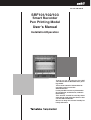
SRF101/102/103
Smart Recorder
Pen Printing Model
User's Manual
Installation/Operation
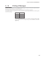
Thank you for purchasing the SRF
101/102/103 Smart Recorder Pen printing model.
This manual contains information for
ensuring correct use of the
SRF101/102/103.
It also provides necessary information
for installation, maintenance, and troubleshooting.
This manual should be read by those
who design and maintain devices that
use the SRF101/102/103.
Be sure to keep this manual nearby for
handy reference.
RESTRICTIONS ON USE
This product has been designed, developed and manufactured for general-purpose
application in machinery and equipment.
Accordingly, when used in applications outlined below, special care should be taken to
implement a fail-safe and/or redundant design concept as well as a periodic
maintenance program.
• Safety devices for plant worker protection
• Start/stop control devices for transportation and material handling machines
• Aeronautical/aerospace machines
• Control devices for nuclear reactors
Never use this product in applications where human safety may be put at risk.
REQUEST
Ensure that this User's Manual is handed over to the user before the
product is used.
Copying or duplicating this User's Manual in part or in whole is forbidden. The information and specifications in this User's Manual are subject to change without notice.
Considerable effort has been made to ensure that this User's Manual is
free from inaccuracies and omissions.
If you should find any inaccuracies or omissions, please contact
Yamatake Corporation.
In no event is Yamatake Corporation liable to anyone for any indirect,
special or consequential damages as a result of using this product.
©1995 Yamatake Corporation ALL RIGHTS RESERVED
The Kim Wipe 4 is a registered trademark of Crecia Co., Ltd.
SAFETY PRECAUTIONS
■ About Icons
The safety precautions described in this manual are indicated by various icons.
Please be sure you read and understand the icons and their meanings described
below before reading the rest of the manual.
Safety precautions are intended to ensure the safe and correct use of this product, to prevent injury to the operator and others, and to prevent damage to property. Be sure to observe these safety precautions.
WARNING
Warnings are indicated when mishandling this
product might result in death or serious injury.
CAUTION
Cautions are indicated when mishandling this
product might result in minor injury to the user, or
only physical damage to the product.
■ Examples
Use caution when handling the product.
The indicated action is prohibited.
Be sure to follow the indicated instructions.
i
WARNING
Do not remove the power supply unit.High-voltage parts are located inside.
Touching these parts might result in electric shock.
Before removing/mounting or wiring the SRF101/102/103, be sure to turn the
source power OFF.
Touching electrically charged parts on the SRF101/102/103 such as
terminals by mistake might cause electric shock.
Be sure to turn the power source OFF before mounting the SRF101/102/103.
Failure to do so might result in electric shock due to a high power supply
voltage.
Before connecting the SRF101/102/103 to the measurement target or
external control circuits, make sure that a protective ground terminal is
connected to the SRF101/102/103.
Failure to do so might cause electric shock or fire.
Be sure to turn the power source OFF before wiring the
SRF101/102/103.Failure to do so might result in electric shock due to a high
power supply voltage.
Power is sometimes supplied to the event wiring even if the SRF101/102/103
is turned OFF. Wire with the power source supply to the event wiring turned
OFF. Failure to do so might cause electric shock due to a high power supply
voltage.
After wiring the leads to terminals, do not allow lead clippings to fall into
mounting bracket holes or ventilation holes. Failure to do so might cause
internal circuits to short-circuit or cause a fire.
Before you start wiring, check the model No. of the SRF101/102/103
(including operational functions), and wire to the correct terminals. When you
have finished wiring, check the numbers again. Wiring the wrong lead to the
wrong terminal might damage the main unit or cause a fire.
Be sure to attach the terminal cover after wiring the SRF101/102/103.
Failure to do so might cause electric shock.
If you have lost the terminal cover, adopt an equivalent measure, or obtain
and attach a maintenance part.
Be sure to turn the power source OFF before changing the DIP switch
setting.
Failure to do might cause electric shock.
ii
CAUTION
Wire the SRF101/102/103 according to predetermined standards. Also wire
the SRF101/102/103 using designated power leads according to recognized
installation methods.
Failure to do might cause electric shock, fire or faulty operation.
Use the SRF101/102/103 within the operating ranges recommended in the
specifications (temperature, humidity, voltage, vibration, shock, atmosphere
etc.). Failure to do so might cause faulty operation.
Do not disassemble the SRF101/102/103, nor touch components inside the
SRF101/102/103.
Doing so might cause electric shock or faulty operation.
Do not touch hot internal components during use or immediately after turning
the power OFF.
Doing so might cause burns.
Do not touch moving parts during operation.
Doing so might cause injury.
Do not operate the keys with the tip of a propelling pencil or sharp-tipped
object.
Doing so might cause faulty operation.
Do not use unused terminals on the SRF101/102/103 as relay terminals.
Use crimped solderless terminals that fit on each terminal screws.
For details, see “■ Recommended Crimped Terminal” on page 3-4.
Adopt sufficient noise countermeasures to prevent malfunction caused by
electrical noise.
Maintain a distance of at least 50 cm between input signal leads and power
leads of 100 V or more. Also, do not pass these leads through the same
piping or wiring duct.
Tighten the mounting bracket while pushing in firmly to prevent a gap with
the panel.
If a gap forms with the panel, the SRF101/102/103 might fall or become
loose which is dangerous.
Be sure to remain the other setting of the DIP switch the same as the factory
setting.
Doing so might cause faulty operation.
iii
Unpacking
■ Check the Model No.
Check the model No. to make sure that you have received the product that you
ordered. The model No. for this product is listed at two places: on the top side of
the case and on the right side of the chassis.
For details of names and parts, see “Chapter 2, Names and Functions of
Parts”(page 2-1).
For details on how to check the model No., see “1-2 Model Selection Guide”
(page 1-3).
■ Check the Contents of the Package to Make Sure That All Accessories Are
Included in The Package
Name
Q’ty
Remarks
Body
1
Standard folding chart (50-sections)
1
No.1 pen (red)
1
No.2 pen (green)
1
2-pen, 3-pen models
No.3 (blue)
1
3-pen model
Printing pen (purple)
1
Mounting bracket set
1
Tag No. plate
1
Terminal screw (spare)
5
Lubricating oil
1
iv
The Role of This Manual
In all, three manuals have been prepared for the SRF101/102/103. Read the manual according to your specific
requirements. The following lists all the manuals that accompany the SRF101/102/103. and gives a brief outline
of the manual:
If you do not have the required manual, contact Yamatake Corporation or your dealer.
SRF101/102/103 Smart Recorder Pen Printing Model User's Manual:
Installtion/Operation
Manual No. CP-UM-1667E
This Manual.
This manual is required reading for those who use the SRF101/102/103,
those who design hardware for integrating the SRF101/102/103 into
operator control panels, those who carry out maintenance, and those who
operate instruments in which the SRF101/102/103 is integrated.
It describes how to install and wire the SRF101/102/103 for integrating into
instruments, method of operation, maintenance and inspection,
troubleshooting, and hardware specifications.
SRF101/102/103/106/201/202/203 CPL Communications
Manual No.CP-UM-1668E
The SRF101/102/103/106/201/202/203 can communicate with other
equipment via the RS-485 or RS-232C interfaces.
This manual describes communications procedures and commands when
the SRF101/102/103/106/201/202/203’s communications features
supported by SRF200 pen printing models are used.This manual is shared
with the SRF200.
SLP-F10/F20 Smart Loader Package
Manual No.CP-UM-5067E
This manual is packaged with the SLP-F10/F20.
Running the SLP-F10/F20 package on a personal computer enables you to
set up SRF100/200 parameters on the personal computer.
This manual describes operations on the personal computer.
This manual is the common manual of the SLP-F10 and the SLP-F20.
v
Organization of This User's Manual
This manual is organized as follows:
Chapter 1. INTRODUCTION
This chapter describes SRF101/102/103 applications and features, and gives a
list of catalog numbers.
Chapter 2. NAMES AND FUNCTIONS OF PARTS
This chapter describes the names and functions of parts on the SRF101/102/103.
Chapter 3. INSTALLATION AND WIRING
This chapter describes precautions, siting conditions and installation method when
installing the SRF101/102/103 into instruments, and how to connect to
peripheral equipment.
Chapter 4. PREPARATION AND OPERATION
This chapter describes checks to carry out before operating the SRF101/102/103
and daily operation procedures.
Chapter 5. BASIC CONFIGURATION
This chapter describes the basic setup details of the SRF101/102/103.
Chapter 6. DETAILED CONFIGURATION
This chapter describes all items that can be set using the operation keys.
Chapter 7. MAINTENANCE
This chapter describes inspection items and how to replace maintenance parts to
ensure prolonged use of the SRF101/102/103.
Chapter 8. TROUBLESHOOTING
This chapter describes points to check when the SRF101/102/103 is not working
properly and how to remedy trouble that might occur.
Chapter 9. SPECIFICATIONS
This chapter describes the general specifications, performance specifications and
external dimensions of the SRF101/102/103.
APPENDIX
This appendix provide you with tables for entering user setting values to the
various setups.
vi
Contents
SAFETY PRECAUTIONS
Unpacking
The Role of This Manual
Organization of This User's Manual
Conventions Used in This Manual
Chapter 1.
INTRODUCTION
1-1 Applications and Features ・ ・・・・・・・・・・・・・・・・・・・・・・・・・・・・1-1
■ Features ・・・・・・・・・・・・・・・・・・・・・・・・・・・・・・・・・・・・・・1-1
■ Optional Functions ・・・・・・・・・・・・・・・・・・・・・・・・・・・・・・・1-2
1-2 Model Selection Guide ・・・・・・・・・・・・・・・・・・・・・・・・・・・・・・・1-3
■ Model Listing ・・・・・・・・・・・・・・・・・・・・・・・・・・・・・・・・・・・1-3
■ Related Parts Model Listing ・・・・・・・・・・・・・・・・・・・・・・・・・・1-3
Chapter 2.
NAMES AND FUNCTIONS OF PARTS
2-1 Main Unit・・・・・・・・・・・・・・・・・・・・・・・・・・・・・・・・・・・・・・・・2-1
■ Front Panel ・・・・・・・・・・・・・・・・・・・・・・・・・・・・・・・・・・・・2-1
■ Inside ・・・・・・・・・・・・・・・・・・・・・・・・・・・・・・・・・・・・・・・2-1
■ Rear Terminal Plate ・・・・・・・・・・・・・・・・・・・・・・・・・・・・・・・2-2
2-2 Display Setup Unit ・・・・・・・・・・・・・・・・・・・・・・・・・・・・・・・・・・2-3
■ Operation Display and Operation Keys ・・・・・・・・・・・・・・・・・・・2-3
■ Configuration Unit and Operation Keys ・・・・・・・・・・・・・・・・・・・2-4
Chapter 3.
INSTALLATION AND WIRING
3-1 Installation Site ・・・・・・・・・・・・・・・・・・・・・・・・・・・・・・・・・・・・3-1
3-2 Installation ・・・・・・・・・・・・・・・・・・・・・・・・・・・・・・・・・・・・・・3-2
■ Installation Dimensions ・・・・・・・・・・・・・・・・・・・・・・・・・・・・3-2
■ Installation Procedure ・・・・・・・・・・・・・・・・・・・・・・・・・・・・・3-2
3-3 Wiring Precautions ・・・・・・・・・・・・・・・・・・・・・・・・・・・・・・・・・3-3
■ Noise Countermeasures ・・・・・・・・・・・・・・・・・・・・・・・・・・・・3-4
■ Recommended Crimped Terminal ・・・・・・・・・・・・・・・・・・・・・・3-4
3-4 Connecting the Power Supply and Ground ・・・・・・・・・・・・・・・・・・・3-5
3-5 I/O Signal Leads ・・・・・・・・・・・・・・・・・・・・・・・・・・・・・・・・・・・3-6
■ Input Terminals ・・・・・・・・・・・・・・・・・・・・・・・・・・・・・・・・・3-7
■ Wiring Relay Outputs (optional function) ・・・・・・・・・・・・・・・・・・3-7
■ Wiring External Switch Inputs (optional function) ・・・・・・・・・・・・・3-7
3-6 Connecting the RS-485 Interface (optional function) ・・・・・・・・・・・・・3-8
3-7 Connecting the RS-232C Interface (optional function) ・・・・・・・・・・・・3-9
vii
Chapter 4.
PREPARATION AND OPERATION
4-1 Loading the Chart ・・・・・・・・・・・・・・・・・・・・・・・・・・・・・・・・・・4-1
■ Loading (replacing) the Chart ・・・・・・・・・・・・・・・・・・・・・・・・・4-1
4-2 Loading (replacing) the Trend Pen and Printing Pen ・・・・・・・・・・・・・4-4
4-3 Operation ・・・・・・・・・・・・・・・・・・・・・・・・・・・・・・・・・・・・・・・4-6
■ Remove of transportation lock screw ・・・・・・・・・・・・・・・・・・・・4-6
■ Starting/stopping Recording ・・・・・・・・・・・・・・・・・・・・・・・・・4-6
■ Feeding the Chart ・・・・・・・・・・・・・・・・・・・・・・・・・・・・・・・・4-7
■ Selecting the Display Mode ・・・・・・・・・・・・・・・・・・・・・・・・・・4-8
■ Recording a Specific Table ・・・・・・・・・・・・・・・・・・・・・・・・・・4-9
■ Other Displays and Operations ・・・・・・・・・・・・・・・・・・・・・・・4-10
■ Printout Details ・・・・・・・・・・・・・・・・・・・・・・・・・・・・・・・・・4-11
Chapter 5.
BASIC CONFIGURATION
5-1 Introduction ・・・・・・・・・・・・・・・・・・・・・・・・・・・・・・・・・・・・・・5-1
5-2 Basic Key Operations at Setup, Key Lock and Extended Menu ・・・・・・・5-2
■ Basic Key Operations at Setup ・・・・・・・・・・・・・・・・・・・・・・・・5-2
■ Canceling Configuration Lock ・・・・・・・・・・・・・・・・・・・・・・・・5-3
■ Switching the Extended Menu ON/OFF ・・・・・・・・・・・・・・・・・・・5-3
5-3 Changing Event Setting Values ・・・・・・・・・・・・・・・・・・・・・・・・・・5-4
5-4 Changing the Chart Feed Speed ・・・・・・・・・・・・・・・・・・・・・・・・・5-5
■ Chart Feed Speed and Tabulation Recording Interval ・・・・・・・・・・5-5
5-5 Changing the Date/Time ・・・・・・・・・・・・・・・・・・・・・・・・・・・・・・5-6
Chapter 6.
DETAILED CONFIGURATION
6-1 Introduction ・・・・・・・・・・・・・・・・・・・・・・・・・・・・・・・・・・・・・・6-1
6-2 Configuration Data and Factory Settings ・・・・・・・・・・・・・・・・・・・・6-2
■ Event Setup (individual channels): EVNT ・・・・・・・・・・・・・・・・・・6-2
■ Chart Feed Speed Setup: SPD ・・・・・・・・・・・・・・・・・・・・・・・・6-2
■ Date/Time Setup: CLK ・・・・・・・・・・・・・・・・・・・・・・・・・・・・・6-2
■ System Setup 1 (individual channels): SYS ・・・・・・・・・・・・・・・・6-2
■ System Setup 2 (individual channels): SYS ・・・・・・・・・・・・・・・・6-3
■ System Setup 3 (individual channels): SYS ・・・・・・・・・・・・・・・・6-3
6-3 Event Setup ・・・・・・・・・・・・・・・・・・・・・・・・・・・・・・・・・・・・・・6-4
■ Event Setup ・・・・・・・・・・・・・・・・・・・・・・・・・・・・・・・・・・・・6-4
■ Description of Event Setup Items ・・・・・・・・・・・・・・・・・・・・・・・6-5
6-4 Chart Feed Speed Setup ・・・・・・・・・・・・・・・・・・・・・・・・・・・・・・6-7
■ Chart Feed Speed Setup ・・・・・・・・・・・・・・・・・・・・・・・・・・・・6-7
■ Description of Chart Feed Speed Setup Items ・・・・・・・・・・・・・・・6-7
6-5 Date/Time Setup ・・・・・・・・・・・・・・・・・・・・・・・・・・・・・・・・・・・6-8
■ Date/Time Setup ・・・・・・・・・・・・・・・・・・・・・・・・・・・・・・・・・6-8
6-6 System Setup 1 (Basic Setup) ・・・・・・・・・・・・・・・・・・・・・・・・・・・6-9
■ System Setup 1 ・・・・・・・・・・・・・・・・・・・・・・・・・・・・・・・・・6-9
■ Description of System Setup 1 Items ・・・・・・・・・・・・・・・・・・・・6-10
viii
6-7 System Setup 2 (Range Setup) ・・・・・・・・・・・・・・・・・・・・・・・・・・6-12
■ System Setup 2 ・・・・・・・・・・・・・・・・・・・・・・・・・・・・・・・・・6-12
■ Description of System Setup 2 (Range Setup) Items ・・・・・・・・・・6-13
6-8 System Setup 3 (Scale Setup) ・・・・・・・・・・・・・・・・・・・・・・・・・・6-15
■ System Setup 3 ・・・・・・・・・・・・・・・・・・・・・・・・・・・・・・・・・6-15
■ Description of System Setup 3 Items ・・・・・・・・・・・・・・・・・・・・6-15
6-9 Range Code Table ・・・・・・・・・・・・・・・・・・・・・・・・・・・・・・・・・6-17
6-10 Character Code Table ・・・・・・・・・・・・・・・・・・・・・・・・・・・・・・・6-19
6-11 External Switch Inputs (Optional Function) ・・・・・・・・・・・・・・・・・・6-20
6-12 Printing of Messages ・・・・・・・・・・・・・・・・・・・・・・・・・・・・・・・6-21
6-13 About Input Filter Function ・・・・・・・・・・・・・・・・・・・・・・・・・・・・6-22
6-14 About Digital Printing Priority ・・・・・・・・・・・・・・・・・・・・・・・・・・6-23
■ Printing Control during a Print Conflict ・・・・・・・・・・・・・・・・・・6-23
■ Simultaneous Printing Control ・・・・・・・・・・・・・・・・・・・・・・・6-23
6-15 ON/OFF of the Reference Junction Temperature Compensation ・・・・・6-24
■ Place of the DIP switch ・・・・・・・・・・・・・・・・・・・・・・・・・・・・6-24
■ Setting the DIP switch ・・・・・・・・・・・・・・・・・・・・・・・・・・・・・6-24
Chapter 7.
MAINTENANCE
7-1 Periodic Inspection ・・・・・・・・・・・・・・・・・・・・・・・・・・・・・・・・・7-1
7-2 Measuring the Display Accuracy of Analog Inputs ・・・・・・・・・・・・・・7-2
■ Equipment Required for Measurement ・・・・・・・・・・・・・・・・・・・7-2
■ Measurement Environment ・・・・・・・・・・・・・・・・・・・・・・・・・・7-2
■ Procedure ・・・・・・・・・・・・・・・・・・・・・・・・・・・・・・・・・・・・・7-2
Chapter 8.
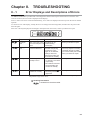
TROUBLESHOOTING
8-1 Error Displays and Descriptions of Errors ・・・・・・・・・・・・・・・・・・・8-1
8-2 Remedying Trouble ・・・・・・・・・・・・・・・・・・・・・・・・・・・・・・・・・8-2
Chapter 9.
SPECIFICATIONS
9-1 Specifications・・・・・・・・・・・・・・・・・・・・・・・・・・・・・・・・・・・・・9-1
■ General Specifications ・・・・・・・・・・・・・・・・・・・・・・・・・・・・・9-1
■ Performance Specifications ・・・・・・・・・・・・・・・・・・・・・・・・・・9-2
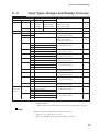
9-2 Input Types, Ranges and Display Accuracy ・・・・・・・・・・・・・・・・・・9-5
9-3 External Dimensions ・・・・・・・・・・・・・・・・・・・・・・・・・・・・・・・・9-7
APPENDIX
User Setup Sheets
● Event Setup ・・・・・・・・・・・・・・・・・・・・・・・・・・・・・・・・・App.-2
● Chart Feed Speed Setup ・・・・・・・・・・・・・・・・・・・・・・・・・・App.-2
● Date/Time Setup ・・・・・・・・・・・・・・・・・・・・・・・・・・・・・・・App.-2
● System Setup 1 ・・・・・・・・・・・・・・・・・・・・・・・・・・・・・・・App.-2
● System Setup 2 ・・・・・・・・・・・・・・・・・・・・・・・・・・・・・・・App.-4
● System Setup 3 ・・・・・・・・・・・・・・・・・・・・・・・・・・・・・・・App.-4
ix
Conventions Used in This Manual
The following conventions are used in this manual:
Handling Precautions
: Handling Precautions indicate items that the user should pay attention
to when handling the SRF101/102/103.
Note
(1)(2)(3)
RCD
: Notes indicate useful information that the user might benefit by
knowing.
: The numbers with the parenthesis indicate steps in a sequence or
indicate corresponding parts in an explanation.
key
key
: These icons represent operation keys and setup keys on the setup
display.
: These indicate 7-segment indications on the data display.
>>
: This indicates the resulting state of the SRF101/102/103 after an
operation.
x
Chapter 1.
1-1
INTRODUCTION
Applications and Features
This multi-input, 1 to 3 pen printing type, high-function recorder accommodates 100mm wide charts. The
SRF101/102/103 offers the dual features of functions and operating ease as a recorder for various equipment and
instrumentation.
It also supports relay output, external switch inputs and communications as optional functions.
■ Features
●
One of the following two groups is specified to each channel as the input type
according to the model No. The input type can be changed freely within that
group.
• Thermocouple/DC voltage (mV, V) group
• Resistance temperature detector (RTD)/DC voltage (mV, V) group
●
Three recording formats are provided and can be freely selected:
• Trend recording
• Trend + tabulation recording
• Trend + schedule demand recording
●
Three measurement methods are provided and can be selected to each channel:
• Measurement value (PV value)
• Deviation value between channels
• Deviation value from fixed value
●
Universal power supply allows use anywhere:
100 to 240Vac, 50/60 Hz
●
Wide range of printing functions:
• Measurement value (PV value)
• Channel No.
• Engineering unit (6 characters per channel)
• Recording scale (Upper/lower limit values)
• Chart feed speed
• Event status (details, time of occurrence/restoration)
• Time marker
• Date
• Time (h:min)
●
Printing at the following start conditions is possible:
• Date
• Time (h:min)
• Recording format
• Chart feed speed
• Recorder ID No.
●
Demand printing also is possible.
Printing is started by the DMD key or external switch input (option), and time
(h:min) and measurement values (PV values) are printed.
●
When trend + schedule demand recording is selected as the recording format,
the measurement value (PV value) of up to four preset times can automatically
be printed.
Messages (six characters each for up to four messages) can be printed together
with time (h:min) data by the remote switch.
●
1-1
Chapter 1. INTRODUCTION
●
●
●
●
Event occurrence and reset are printed together with time (h:min) data.
Printing of “Date/Time (h:min)”, “Scale” and “Event” can be disabled.
Setup data is protected in EEPROM when the power is OFF.
Pen phase synchronization is provided in the standard specification.
For details, see “● About pen phase synchronization” (page 6-10).
■ Optional Functions
The following optional functions are available:
1-2
●
Relay outputs
6 outputs: SPDT relay output
●
External switch inputs (remote switch input)
4 inputs: recording ON/OFF, Demand printing, Chart feed, Print messages No.1
to No.4.
●
Communications
RS-485, RS-232C
Chapter 1. INTRODUCTION
1-2
Model Selection Guide
■ Model Listing
Basic
model No.
Power Input
code
Option 1
Option 2
Option 3
Addition 1 Addition 2
Specifications
SRF101
100mm 1pen
SRF102
100mm 2pen
SRF103
100mm 3pen
A
AC100 to 240V, 50/60Hz
A to F
Semi multi-input (standard specification)*
0
None
1
Relay outputs (6)
2
Relay outputs (6)+external switch inputs (4)
0
Communications not supported
1
RS-485
2
RS-232C
0
None
0
None
D
Inspection certificate provided
T
Tropical treatment
B
Inspection Certificate provided+Tropical treatment
0
None
* Semi multi-input
SRF101
Input
code
SRF101
SRF102
SRF103
No.1 Pen
T/C, mV, V
A
B
C
D
E
F
SRF103
SRF102
No.2 Pen
RTD, mV, V
T/C, mV, V
❍
No.3 Pen
RTD, mV, V
❍
T/C, mV, V RTD, mV, V
❍
❍
❍
❍
❍
❍
❍
❍
❍
❍
❍
❍
❍
❍
❍
❍
■ Related Parts Model Listing
● Accessories
Name/Specification
SRF101
SRF102
SRF103
Folding chart 50-sections (1)
❍
❍
❍
No.1 pen (red 1)
❍
❍
❍
No.2 pen (green 1)
-
❍
❍
No.3 pen (blue 1)
-
-
❍
Printing pen (purple 1)
❍
❍
❍
Mounting bracket (1 set)
❍
❍
❍
Tag No. plate (1)
❍
❍
❍
Terminal screw (spare 5)
❍
❍
❍
Lubricating oil (1)
❍
❍
❍
1-3
Chapter 1. INTRODUCTION
● Consumables (sold separately)
Name
Folding chart, 50-section
Folding chart with EcoMark
(recycled paper), 40-section
Folding chart with EcoMark
(recycled paper), 50-section
Folding chart with EcoMark
(recycled paper), 60-section
Folding chart with EcoMark
(recycled paper), 70-section
Folding chart with EcoMark
(recycled paper), 75-section
Clean paper chart 50-section
Spare 1st pens
Spare 2nd pens
Spare 3rd pens
Spare plotter pens
Lubricating oil
Model No.
Application Range (example)
81406088-001 0,20,40,60,80,100
81409977-004 0,10,20,30,40
0,20,40,60,80
0,50,100,150,200
The above 3 patterns are printed.
81409977-001 0,10,20,30,40,50
0,20,40,60,80,100
0,40,80,120,160,200
The above 3 patterns are printed.
81409977-002 0,10,20,30,40,50,60
0,20,40,60,80,100,120
0,50,100,150,200,250,300
The above 3 patterns are printed.
81409977-003 0,2,4,6,8,10,12,14
Remarks
10 packets, 16m
10 packets, 16m
81409977-005 0,50,100,150
10 packets, 16m
81407115-001 For clean room, 0 to 100%
81446293-001
81446294-001
81446295-001
81446296-001
81446513-001
10 packets, 12m
Red 3 pens
Green 3 pens
Blue 3 pens
Purple 3 pens
10 packets, 16m
10 packets, 16m
10 packets, 16m
● Optional Parts (sold separately)
Name
250Ω resistor
250Ω resistor
DC divider input
Carrying handle kit
RS-232C cross cable
Analog scale plate
Model No.
81401325
81446642-001
81446627-001
81446643-001
CBL232FNZ02
Remarks
Accuracy ±0.02%, 1 pc.
Accuracy ±0.05%, 2 pcs.
1/1000 voltage divider resistance
With carrying handle, rubber legs and power cable
1 cable
Contact your dealer.
● Maintenance Parts (sold separately)
Name
Tag plate
Mounting bracket
Replacement door
Chart cassette
Chart holder
Chart guide
Model No.
81446509-001
81446510-001
81446500-001
81446501-001
81446502-001
81446503-001
Power terminal cover
Analog input terminal cover
External switch input/
Communications terminal cover
Relay output terminal cover
Terminal screw
Power cable
81446504-001
81446505-001
81446652-001
Remarks
10 sheets
1 set (2 brackets)
With pin and spring
Unit ass’y component
Plastic formed component(black)
Plastic formed component
(transparent)
81446508-001
81446511-001 10 screws
81446475-001
● Smart Loader Package (SLP)
Name
Smart loader package
1-4
Model No.
SLP-F10✽✽✽
Remarks
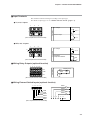
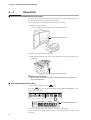
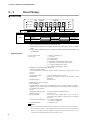
Chapter 2. NAMES AND FUNCTIONS OF PARTS
2-1
Main Unit
WARNING
Do not remove the power supply unit.
High-voltage parts are located inside. Touching these parts might result in
electric shock.
■ Front Panel
Door
Chart guide
Folding chart
SET
Tag plate
ENT FEED DMD RCD DISP
CH
EVNT
DATA
EVNT/EVNT
RCD
POC/SPD
DMD
LOCK/CLK
SYS
Loader jack
■ Inside
Mounting hole(for mounting bracket)
Case
Pen(holder)
Model No. lavel
Analog scale plate
Transportation lock screw holder
Chassis
Model No. lavel
Internal mechanism
Transportation lock screw
2-1
Chapter 2. NAMES AND FUNCTIONS OF PARTS
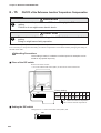
■ Rear Terminal Plate (3-pen model supporting optional functions)
The figure below shows an example of the rear terminal plate for a 3-pen model
supporting optional functions.
The shape of input terminals varies according to the semi-multi-input type (see
page 1-3).
For details, see “Chapter. 3 INSTALLATION AND WIRING”.
Communications terminals (optional functions)
1
2
3
4
5
RS-485
SDA SDB RDA RDB SG
RS-232C
SD
- RD SG
Communications interface
External switch input terminals(optional functions)
1
2
3
4
5
6
RSW1 RSW2 RSW3 RSW4
COM
Power terminals
Ground terminal
12 345
1 23456
Input terminals
TC, mV, V
+
Not used
2-2
RTD, mV, V
A
B
C
1
2
3
1 2 3 4 5 6
N.O
COM
N.C
Relay output terminals
(optional functions)
Chapter 2. NAMES AND FUNCTIONS OF PARTS
2-2
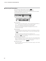
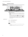
Display Setup Unit
■ Operation Display and Operations Keys
The following describes the operation panel on the display setup unit:
● Operation keys
SET
ENT FEED DMD RCD DISP
Display key:
Returns from setup/display selection.
Record key:
Start/stops recording.
Demand key:
Starts demand printing.
Feed key:
Feeds chart for the duration that
this key is held down.
● Operation display
Lights during demand printing.
Lights during recording.
CH
EVNT
DATA
EVNT/EVNT
RCD
POC/SPD
DMD
LOCK/CLK
SYS
Data display
(7-segment LEDs are used. Two LEDs from left facing the front
are red. Others are green.)
EVNT/EVNT: Lights when an event occurs.
POC/SPD:
Lights when pen phase synchronization is functioning.
LOCK/CLK: Lights when configuration lock is functioning.
Display examples
CH
EVNT
DATA
AUTO or MAN indicates the PV input value.
The example on the left shows a value of 18.0
CH
EVNT
for channel 1
DATA
CLK indicates the date.
The example on the left shows the date April (04) 27th (27)
1998 (98) . In this example, the 8 in 98 is displayed red.
CH
EVNT
DATA
CLK indicates the time.
The example on the left shows the time
10:10 .
2-3
Chapter 2. NAMES AND FUNCTIONS OF PARTS
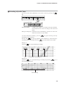
■ Configuration Unit and Operation Keys
The following describes the configuration unit on the display setup unit:
● Setup keys
SET
ENT FEED DMD RCD DISP
Enter key:
Shifts the menu number, and
fixes numerical values.
Up key:
Changes (increments) numerical values.
Shift key:
Shifts the digit (cursor).
Set key:
Enters the setup mode, and selects setup items.
● Setup display
EVNT/EVNT: Lights when the event is being set up.
POC/SPD:
Lights when the chart feed speed is being set up.
LOCK/CLK: Blinks when the date and time are being set up.
CH
EVNT
DATA
EVNT/EVNT
RCD
POC/SPD
DMD
LOCK/CLK
SYS
SYS: Lights when system setup 1 (basic setup) is being set up.
Blinks at 1-second intervals when system setup 2 (range setup) is being set up.
Blinks at 2-second intervals when system setup 3 (scale setup) is being set up.
Display examples
CH
DATA
RCD
POC/SPD
DMD
LOCK/CLK
SYS
CH
EVNT
DATA
EVNT/EVNT
RCD
POC/SPD
DMD
LOCK/CLK
SYS
CH
EVNT
DATA
EVNT/EVNT
RCD
POC/SPD
DMD
LOCK/CLK
SYS
CH
EVNT
DATA
EVNT/EVNT
RCD
POC/SPD
DMD
LOCK/CLK
SYS
CH
EVNT
DATA
EVNT/EVNT
RCD
POC/SPD
DMD
LOCK/CLK
SYS
CH
2-4
EVNT
EVNT/EVNT
EVNT
DATA
EVNT/EVNT
RCD
POC/SPD
DMD
LOCK/CLK
SYS
Event setup in progress
In the example on the left, event setup 3 (event
type) on channel 1 is being set up.
Chart feed speed setup in progress
In the example on the left, the chart feed speed is
40 mm/h .
Date/time setup in progress
In the example on the left, the date is
1998, April 27 .
System setup 1 (basic) setup in progress
In the example on the left, the key lock is OFF (0) .
System setup 2 (range) setup in progress
In the example on the left, the recording mode on
channel 1 is trend+tabulation .
System setup 3 (scale) setup in progress
In the example on the left, the scale lower limit
value on channel 1 is 0.0 .
Chapter 3.
3-1
INSTALLATION AND WIRING
Installation Site
The SRF101/102/103 is for indoor installation only. Install the SRF101/102/103 at a location that satisfies the
following conditions:
• Locations that are hardly subject to temperature change. Locations close to room
temperature
• Locations that are not subject to corrosive gas
• Locations whose humidity is neither too low nor too high
• Locations that are hardly subject to mechanical vibration
• Locations that are hardly subject to dust or oil smoke
• Locations that are hardly subject to the influence of electrical noise
• Locations that are not subject to magnetic fields
Handling Precautions
• Keep the mounting angle to within 0 to 30° from the bottom rear (bottom
rear angle) or to within 0 to 3° from the top rear (top rear angle).
• Use a steel panel of at least 2 to 6 mm in thickness for mounting the
SRF101/102/103.
● When mounting from bottom rear
Panel thickness 2 to 6 mm
Panel
Door
0 to 30˚ bottom rear angle
from horizontal position
● When mounting from top rear
Panel thickness 2 to 6 mm
Panel
0 to 3˚ bottom rear angle
from horizontal position
Door
3-1
Chapter 3. INSTALLATION AND WIRING
3-2
Installation
WARNING
Be sure to turn the power source OFF before mounting the SRF101/102/103.
Failure to do so might result in electric shock due to a high power supply
voltage.
CAUTION
Tighten the mounting bracket while pushing in firmly to prevent a gap with the
panel.
If a gap forms with the panel, the SRF101/102/103 might fall or become loose
which is dangerous.
■ Installation Dimensions
The panel cutout dimensions are as follows:
138 +1
0
200 min.
138 +1
0
(unit:mm)
200 min.
■ Installation Procedure
Mount the SRF101/102/103 by fastening the mounting bracket in the mounting holes at
the top and bottom of the case.
Handling Precautions
The recommended tightening torque for the mounting bracket is 1.0 to 1.5
N • m. Tightening the mounting bracket with a torque higher than this might
deform the case or damage the mounting bracket.
3-2
Chapter 3. INSTALLATION AND WIRING
3-3
Wiring Precautions
WARNING
Before wiring the SRF101/102/103, be sure to turn the power OFF.
Failure to do so might cause electric shock depending on the power voltage.
Power is sometimes supplied to the event wiring even if the SRF101/102/103
is turned OFF. Wire with the power source supply to the event wiring turned
OFF. Failure to do so might cause electric shock due to a high power supply
voltage.
After wiring the leads to terminals, do not allow lead clippings to fall into
mounting bracket holes or ventilation holes. Failure to do so might cause
internal circuits to short-circuit or cause a fire.
Before you start wiring, check the model No. of the SRF101/102/103
(including operational functions), and wire to the correct terminals. When you
have finished wiring, check the numbers again. Wiring the wrong lead to the
wrong terminal might damage the main unit or cause a fire.
Be sure to attach the terminal cover after wiring the SRF101/102/103.
Failure to do so might cause electric shock.
If you have lost the terminal cover, adopt an equivalent measure, or obtain
and attach a maintenance part.
CAUTION
Do not use unused terminals on the SRF101/102/103 as relay terminals.
Use crimped solderless terminals that fit on each terminal screws.
For details, refer to “■ Recommended Crimped Terminal” on page 3-4.
Adopt sufficient noise countermeasures to prevent malfunction caused by
electrical noise.
Maintain a distance of at least 50 cm between input signal leads and power
leads of 100 V or more. Also, do not pass these leads through the same
piping or wiring duct.
3-3
Chapter 3. INSTALLATION AND WIRING
■ Noise Countermeasures
CAUTION
Maintain a distance of at least 50 cm between input signal leads and power
leads of 100 V or more. Also, do not pass these leads through the same
piping or wiring duct.
Digital equipment is easily influenced by electrical noise. Conditions that are not a problem
on analog equipment might cause digital equipment to become damaged or malfunction.
When wiring, pay sufficient attention to the following items to prevent the influence of
electrical noise:
● Noise generating sources
Generally, the following generate electrical noise:
(1) Relays and contacts
(2) Solenoid coils, solenoid valves
(3) Power lines (in particular, 100V ac min.)
(4) Induction loads
(5) Motor commutators
(6) Inverters
(7) Phase angle control SCR
(8) Wireless communications equipment
(9) Welding equipment
(10)High-voltage ignition equipment
● Noise reducing countermeasures
If the influence of electrical noise cannot be eliminated, we recommend taking the
following countermeasures:
• Provision of a CR filter for fast-rising noise
Recommended CR filter: Yamatake Corporation Model No. 81446365-001
• Provision of a varister for noise with a high wave height
Recommended varister:
Yamatake Corporation Model No. 81446366-001 (100 V)
81446367-001 (200 V)
However, note that the varister may become short-circuited when trouble occurs. Pay
attention to this when providing a varister on the SRF101/102/103.
■ Recommended Crimped Terminal
Use crimped solderless terminals that conform to the following dimensions for each of the
terminals.
Terminal Name
Applicable Crimped Terminal (unit: mm)
4.3 dia. min.
Screw Dia.
M4
8.5 max.
Power terminals Ground terminal
M3.5
3.8 min.
Input terminal
Relay output terminals
(optional function)
External switch input terminals
(optional function)
Communications terminal
(optional function)
8 max.
8 max.
3.8 dia. min.
Handling Precautions
When wiring with crimped solderless terminals, take care to prevent contact with
adjacent terminals.
3-4
Chapter 3. INSTALLATION AND WIRING
3-4
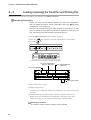
Connecting the Power Supply and Ground
• Use 600 V vinyl-insulated power lead (JIS C 3307) as the power supply lead.
• Obtain the SRF101/102/103 power supply from a single-phase instrumentation
power supply not subject to excess noise.
• If the power supply generates excessive noise, add an insulating transformer,
and a use a line filter.
Recommended line filter: Yamatake Corporation 81446364-001)
• Keep wiring from the line filter as short as possible. Bundling this wiring
together is effective against electrical noise.
• After providing anti-noise countermeasures, do not bundle primary and
secondary power leads together, or pass them through the same piping or wiring
duct.
• Connect the SRF101/102/103 by one-point grounding to the protective ground
terminal. Do not perform any jumping wiring. When it is difficult to ground
shielded cables, prepare a separate ground terminal (earth bar).
• Grounding type: Lower than 100Ω
• Grounding conductor: Annealed copper wire 2 mm2 (AWG14) or more
• Grounding conductor length: Max. 20 m
Recommended product
81446364-001
Line filter
200/200 V
100/100 V
Insulation transformer
Instrument
power supply
1
100 to 240Vac
50/60 Hz
SRF101/102/103
3
E
Ground
2
Other circuits
4
Ground
Handling Precautions
Use a power switch or fuse designed to take rush current into
consideration when installing the power switch or fuse outside the
SRF101/102/103.
3-5
Chapter 3. INSTALLATION AND WIRING
3-5
I/O Signal Leads
● Thermocouple input signal lead
In the case of thermocouple input, connect the bare thermocouple lead to the
terminal. If the thermocouple is located a long way from the SRF101/102/103, or
the thermocouple is connected to a terminal, extend the connection using a
compensating lead and then connect to the terminal. Use shielded compensating
leads only.
● Resistance temperature detector (RTD)
• Use the three conductors.
• For the conductor, use JKEV-SB (JCS4364) instrument cable or equivalent
product. (This is generally referred to as “twisted shielded cable for
instruments.”)
• The wiring resistance is 10 Ω or less per conductor.
• Balance the resistances of the three conductors so that they are the same values.
● Analog inputs other than thermocouple and resistance temperature detector (RTD) and
digital I/O leads
• Use twisted shielded cable for instruments.
• Shielded, multi-core microphone cord (MVVS) can be used if there is relatively
little electromagnetic induction.
Note
• Use no-voltage contact inputs, and assign these contacts for minute currents.
(input no-load voltage: approx. 5V, input short-circuit current: approx. 6mA)
• Hold contact signals for 0.5seconds or more.
Handling Precautions
Be careful not to short-circuit across communications terminals SDA
and SDB, or across RDA and RDB. Otherwise, this might damage the
communications path.
3-6
Chapter 3. INSTALLATION AND WIRING
■ Input Terminals
The terminal connection changes according to the input type.
For details on input type, see “1-2 Model Selection Guide” (page 1-3).
● TC, mV, V inputs
1
2
3
+
DC voltage
Connection
+
—
mV, V
—
+
Thermocouple
T/ C
(M3.5 crimped terminal recommended)
—
● RTD, mV, V inputs
1
2
3
+
DC voltage
Connection
A
B
C
mV, V
—
Resistance
temperature detector
A
B
(M3.5 crimped terminal recommended)
RTD
C
■ Wiring Relay Outputs (optional function)
1 2 3 4 5 6
COM
N.C
Indicator lamp
N.O
Connection
N.O
COM
N.C
(M3.5 crimped terminal recommended)
■ Wiring External Switch Inputs (optional function)
RSW1
1 2 3 4 5 6
RSW2
COM
COM
RSW4
RSW3
RSW2
RSW1
RSW3
RSW4
1
2
3
4
5
6
COM
(M3.5 crimped terminal recommended)
3-7
Chapter 3. INSTALLATION AND WIRING
3-6
Connecting the RS-485 Interface (optional function)
Read this section when you are using a model that supports the RS-485 communications functions.
The below shows an example with the RS-485 interface connected. In this example, the SRF101/102/103 is the
slave instrument.
1
2
3
4
5
SRF101/102/103
(slave instrument)
Terminator
resistor
Terminal No.
Signal
1
2
SDA SDB
3
4
5
RDA
RDB
SG
SDA
SDB
RDA
RDB
SG
Terminator
resistor
(M3.5 crimped terminal recommended)
FG
Shielded cable
Master station
RDA
RDB
SDA
SDB
SG
FG
Shielded cable
SRF101/102/103
(slave instrument)
SDA
SDB
RDA
RDB
SG
FG
Shielded cable
Terminator
resistor
Terminator
resistor
SRF101/102/103
(slave instrument)
SDA
SDB
RDA
RDB
SG
FG
Provide terminators of resistance 150Ω±5%, 1/2W min. at both ends of the
communications path.
Grounding of the shielded FG terminal should be carried out at only one end and
not both ends.
Handling Precautions
Be sure to connect SG terminals each other.
Failure to do so might cause unstable communications.
3-8
Chapter 3. INSTALLATION AND WIRING
3-7
Connecting the RS-232C Interface (optional function)
Read this section when you are using a model that supports the RS-232C communications functions.
1
2
1
2
3
4
5
SD
-
RD
-
SG
Terminal No.
Signal
3
4
5
(M3.5 crimped terminal recommended)
(connection example)
FG
FG
1
SD
2
RD
RD
3
SD
RS
4
CS
DR
SG
CD
ER
5
6
SG
7
8
20
Host computer
(master instrument)
Shielded
cable
SRF101/102/103
(slave instrument)
Note
Cable model No.: CBL232FNZ02 (2m cross-cable for RS-232C)
3-9
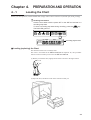
Chapter 4.
4-1
PREPARATION AND OPERATION
Loading the Chart
Before you start operation, load the folded chart (simply called “chart” from here on) and the pen (trend, printing).
Handling Precautions
Load the chart either with the power OFF or the SRF101/102/103 in a
recording stop state.
To set to a recording stop state during recording, press the RCD key.
The RCD LED goes out.
SET
ENT FEED DMD RCD DISP
CH
EVNT
DATA
EVNT/EVNT
RCD
POC/SPD
DMD
LOCK/CLK
SYS
Recording progress LED
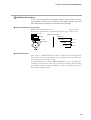
■ Loading (replacing) the Chart
The describes below how to load the chart.
The chart is not loaded in the SRF101/102/103 at shipment. So, this procedure
must be carried out when you first use the SRF101/102/103.
(1) Before you load the chart, lightly fan the chart as shown in the figure below:
(2) Open the door, and draw out the chart cassette towards you.
4-1
Chapter 4. PREPARATION AND OPERATION
(3) Open out the chart guide (made of transparent plastic) using its bottom side as
a fulcrum, and open out the chart holder.
Chart holder
Chart guide
(4) Fan the chart, insert it into the rear of the chart cassette from the top making
sure that it is facing the correct direction, and draw its leading edge out towards
the chart guide.
Handling Precautions
A chart feed error will occur if the chart is not loaded correctly into the
chart holder.
(5) Fit three to five folds from the leading edge of the chart on the tray on the chart
guide side, and correctly align them on the sprockets.
Sprockets(holes)square
Sprockets(holes)oblong
4-2
Chapter 4. PREPARATION AND OPERATION
(6) Attach the chart holding spring so that the hooks on the oblong hole side of the
chart are under the protrusion on the chart cassette.
(7) Push in the chart guide so that the left and right latches are firmly hooked, and
close the chart guide.
(8) Gently push the chart cassette into the body as far as possible.
Handling Precautions
After you have attached the chart cassette, feed the chart by about one
fold by pressing the FEED key to make sure that the chart is fed
properly before you start recording. If the power is not ON, turn the
power ON and feed the chart by about one fold.
Note
For details on the chart part No., see “1-2 Model Selection Guide” (page 13).
4-3
Chapter 4. PREPARATION AND OPERATION
4-2
Loading (replacing) the Trend Pen and Printing Pen
Test the pens to see that they write before you load them in the SRF101/102/103.
Handling Precautions
• Before you carry out the following operations, cancel the configuration
lock. For details on how to cancel configuration lock, see “■ Canceling
Configuration Lock” (page 5-3).
• After you have removed the pen caps, be sure to store them in a safe
place. If operation of the SRF101/102/103 is stopped for more than one
day, remove the pens and store them with their caps on.
(1) Set the SRF101/102/103 to the recording stop state.
(2) Press the
DISP
(3) Press the
key, and set to one of the AUTO, MAN or CLK modes.
key.
SET
ENT FEED DMD RCD DISP
CH
EVNT
DATA
EVNT/EVNT
RCD
POC/SPD
DMD
LOCK/CLK
SYS
>>The pens move as shown in the following figure.
No.2 pen holder(green)
(SRF102, SRF103)
No.3 pen holder(blue)
(SRF103)
No.1 pen holder(red)
Printing pen holder
(4) Draw out the chart cassette.
(5) Remove the pen caps.
Load the pens in order from the bottom: printing pen, No.3 pen, No.2 pen and
No.1 pen.
(6) Rotate the analog scale plates of each of the pens upwards so that the pen
holder can be seen from the front to load the pens. The scales return if you
release your finger. So, carry out this work with the scales held down.
Handling Precautions
The number of pens varies according to the model No.
4-4
Chapter 4. PREPARATION AND OPERATION
Note
You can load the pens more easily by inserting them slightly at an angle
instead of inserting them straight from the front of the holder.
(7) When you have finished loading the pens, raise the pen lift lever, and attach the
chart cassette.
(8) Press the
key to return the pens to their original positions before they
were replaced.
(9) Press the RCD key to start recording. Make sure that initial printing and
trend printing can be carried out without any problems.
Note
The life of trend pens is about 1200 meters, and the life of the printing pen is about
80,000 characters.
• Spare 1st pens (contains 3 red pens):
Model No. 81446293-001
• Spare 2nd pens (contains 3 green pens):
Model No. 81446294-001
• Spare 3rd pens (contains 3 blue pens):
Model No. 81446295-001
• Spare plotter pens (contains 3 purple pens):
Model No. 81446296-001
Handling Precautions
It may not able to operate normally when it is used with the analog scale
plate swung up.
4-5
Chapter 4. PREPARATION AND OPERATION
4-3
Operation
■ Remove of transportation lock screw
It is fixed on the case with the transportation lock screw to prevent the jump-out of
the internal mechanism at the time of the transport.
Take the next when the transportation lock screw is fastened.
(1) Remove the chart cassette.
>>You can find the transportation lock screw inside the case.
Transportation lock screw
(2) Remove the transportation lock screw.
(3) Keep the transportation lock screw in the following screw holder so that it may
prevent loss.
Transportation lock screw holder
Handling Precautions
Fix the internal mechanism with the transportation lock screw at the
time of the transport.
■ Starting/stopping Recording
To start/stop recording, press the
RCD
key.
Press the RCD key. The RCD LED lights, and the SRF101/102/103 is set to
the recording stop state.
SET
ENT FEED DMD RCD DISP
CH
EVNT
DATA
EVNT/EVNT
RCD
POC/SPD
DMD
LOCK/CLK
SYS
Recording progress LED
If you press this key again, the LED goes out, and recording stops.
When recording starts, the following items are printed out (this is called “initial
printing”):
4-6
Chapter 4. PREPARATION AND OPERATION
•
•
•
•
•
Year/Month/Date (last two digits of Western calendar)
Time (h/min)
Recording format
Chart feed speed
Recorder ID No. (The ID No. is not printed when “00” is set as the ID No.)
Initial printing is not carried out when the power is turned OFF and then ON again
in a recording start state. (The operation is the same in the event of an
instantaneous power interruption.)
The recording stop/start state is held in memory even if the power is OFF. The
same state is returned to when power is next turned ON.
■ Feeding the Chart
To feed the chart forwards when recording is stopped, hold down the
To stop chart feed, release your finger from the key.
SET
FEED
key.
ENT FEED DMD RCD DISP
CH
EVNT
DATA
EVNT/EVNT
RCD
POC/SPD
DMD
LOCK/CLK
SYS
Handling Precautions
• You cannot operate the FEED key during recording.
• To feed the chart backwards, remove the chart cassette, manually
fold back the chart to its original position, and attach the chart
cassette into the body again.
4-7
Chapter 4. PREPARATION AND OPERATION
■ Selecting the Display Mode
You can select four display modes by pressing the
DISP
key.
When the recording mode selection for all the channels is set to
"0:display/recording OFF", the selection can be made only for the CLK indicator
(year/month/date) and CLK indicator (time).
SET
ENT FEED DMD RCD DISP
CH
EVNT
DATA
EVNT/EVNT
RCD
POC/SPD
DMD
LOCK/CLK
SYS
✠ AUTO indicator
This mode successively displays the PV value of each channel automatically “1,
2, 3, 1 ... and so forth” at 4-second intervals on the DATA display.
When AUTO is displayed, the decimal point of channel blinks.
However, when the number of channels to be displayed is only one, the
selection cannot be made.
✠ MAN indicator
This mode displays the selected specific channel on the CH display, and the PV
value of that channel on the DATA display. To move to the next channel, press
the
key.
When MAN is displayed, the decimal point of channel goes out.
However, when the number of channels to be displayed is only one, the display
selection by the
key cannot be made.
✠ CLK indicator (year/month/date)
This mode displays the lower two digits of the year on the CH and EVENT
displays, and the date using the lower four digits of the DATA display. For
example, in the case of April 27th, “
” is displayed.
✠ CLK indicator (time)
This mode displays the time (h:min) on the DATA display. The CH and
EVENT displays go out.
4-8
Chapter 4. PREPARATION AND OPERATION
■ Recording a Specific Table
You can record a table (tabulation) of current PV values by pressing the
key.
SET
DMD
ENT FEED DMD RCD DISP
CH
EVNT
DATA
EVNT/EVNT
RCD
POC/SPD
DMD
LOCK/CLK
SYS
During recording:
A table of PV values is recorded overlaying trend data.
The tabulation time varies according to the chart feed
speed.
During recording stop: Tabulation starts immediately, and ends in about one
minute 30 seconds on a 3-pen model.
To cancel tabulation midway, press the
immediately stops tabulation.
DMD
key again. Pressing this key
RCD
Pressing the
key during tabulation after tabulation is started during a
recording stop is not accepted. Press the RCD key after tabulation has ended.
Example 1)
(when the DMD key is pressed during recording)
Time
PV of channel 1 PV of channel 2 PV of channel 3
Example 2)
(when the DMD key is pressed during a recording stop and the
pressed during tabulation)
RCD
key is
Demand printing
4-9
Chapter 4. PREPARATION AND OPERATION
■ Other Displays and Operations
● Display when an event occurs
When an event occurs, the EVNT/EVNT LED lights. When the display mode is
set to AUTO or MAN, the status of the event is displayed for the channel where
the event occurred.
(Example)
The “ ” (HIGH) event occurs on channel 1 (PV value: 520.4)
CH
EVNT
DATA
EVNT/EVNT
RCD
POC/SPD
DMD
LOCK/CLK
SYS
HIGH (upper limit) event
LOW (lower limit) event
high (absolute value deviation upper limit) event
low (absolute value deviation lower limit) event
HIGH. (rate-of-change upper limit) event
LOW. (rate-of-change lower limit) event
Different events are occurring simultaneously.
● Configuration lock
“Configuration lock” is a feature for preventing the user from changing
configuration setups by mistake. When the configuration is locked, setups can be
confirmed but not changed.
When the configuration is locked, the LOCK/CLK LED lights. For details on how
to cancel configuration lock, see “■ Canceling Configuration Lock” (page 5-3).
SET
ENT FEED DMD RCD DISP
CH
4-10
EVNT
DATA
EVNT/EVNT
RCD
POC/SPD
DMD
LOCK/CLK
SYS
Chapter 4. PREPARATION AND OPERATION
■ Printout Details
● Printout messages (purple)
Massage printing
Note
For details, see “6-12 Printout Messages” (page 6-21).
● Example of trend + tabulation recording, and recording when an event occurs
Tabulation recording
Note
Digital printing is carried out when the chart feed speed is 150mm/h or less.
4-11
Chapter 5.
5-1
BASIC CONFIGURATION
Introduction
To use the SRF101/102/103, you must first select the input range type, and set the recording scale, chart feed
speed and other items. This setup is called “configuration.”
Configuration is sometimes already set up by the device manufacturer in which the SRF101/102/103 is
integrated. If the SRF101/102/103 has not been configured or you want to change the configuration setups, refer
to “Chapter 6, Detailed Configuration.”
On the SRF101/102/103, configuration is divided into two stages:
• For personnel who normally operate the SRF101/102/103.
• For personnel who initially set up the SRF101/102/103.
This chapter describes the setup items listed below whose settings are changed relatively often in normal operation.
When the extended menu is set to OFF, three setup items (event setting value, chart feed speed and date/time) can
be set. This chapter describes these setup items.
When the extended menu is set to ON, input range type, recording scale, recording format selection, event type and
system setup can be set. Chapter 6, Detailed Configuration describes all of these setup items.
Configuration Lock Canceled
Extended menu OFF
Event setting value
Chart feed speed
Date/time setup
Extended menu ON
The following items are added
to extended menu OFF:
Input range type
Recording scale
Recording format selection
Event type selection
System setup
Note
When the configuration is locked, setups can be displayed for confirmation
but not changed. (The configuration lock can be canceled at any time.)
Handling Precautions
• Data setups can be changed during recording. Note, however, that
display recording may end in error depending on details of the
change, for example, input type.
• The factory setting of the extended menu entry is “0(OFF)”.
5-1
Chapter 5. BASIC CONFIGURATION
5-2
Basic Key Operations at Setup, Key Lock and Extended Menu
■ Basic Key Operations at Setup
This section describes common operations at setup.
The figure below shows the display setup unit.
● To start configuration setup
Press the
SET
key.
SET
ENT FEED DMD RCD DISP
CH
EVNT
DATA
EVNT/EVNT
RCD
POC/SPD
DMD
LOCK/CLK
SYS
● To change configuration items
SET
Press the
key to advance to the next display number.
● To quit configuration
Pressing the
DISP
key in any situation quits configuration.
● To advance to the next display number
Press the
key. The cursor shifts to the display number digit (red LED). Press
the
key to shift the display number.
Note
If you have not changed the numerical values of a setup item, pressing the
ENT
key shifts the display number without changing the setup.
● To change data
Shift the cursor (blinking digit) using the
key to DATA.
Press the
key to fix the data, and set the data with the ENT key.
To increment numerical values, press the
key.
When the valid minimum or maximum value of the data is reached, pressing the
key does not change the numerical value. To set the numerical value, press
ENT
the
key.
Note
To cancel changing of data midway, press either of the following keys without
pressing the ENT key. Any changes made to the currently displayed data at
this time are not implemented.
DISP
key : Quits configuration
SET
key
: Advances to the next setup.
You can advance the display number without changing the data by pressing
the
keys after shifting the cursor to the display number digit (red LED).
Handling Precautions
If a setting value is in error, all data will blink when you press the
key. If this happens, press any key to return to the entry display.
Check the setting values, and reset them if necessary.
5-2
ENT
Chapter 5. BASIC CONFIGURATION
■ Canceling Configuration Lock
When the configuration is locked, the LOCK/CLK LED lights and the configuration
setup cannot be changed.
To cancel configuration lock, follow the procedure below:
CH
EVNT
DATA
EVNT/EVNT
RCD
POC/SPD
DMD
LOCK/CLK
SYS
(1) Press the SET key to select SYS.
>>The SYS LED lights.
CH
EVNT
DATA
EVNT/EVNT
RCD
POC/SPD
DMD
LOCK/CLK
SYS
(2) Change the configuration lock setting from “1” to “0” in display number 1.
(3) Press the ENT key.
>>The LOCK/CLK LED goes out to indicate that the configuration lock is
canceled.
■ Switching the Extended Menu ON/OFF
To set initial settings such as range type and recording scale on the
SRF101/102/103, turn the extended menu ON.
(1) Press the SET key to select SYS.
>>The SYS LED lights.
(2) Press the ENT key to change the extended menu setting from “0(OFF)” to
“1(ON)” in display No.2.
(3) Press the ENT key.
5-3
Chapter 5. BASIC CONFIGURATION
5-3
Changing Event Setting Values
Handling Precautions
Event setting values are displayed when an event type other than “–” is
set. For details on how to set up event types, see page 6-4.
The decimal point position of event setting values is the decimal point
position determined by the range code in the case of range codes 200
onwards. In the case of range code 100 to 105 DC voltage inputs, this
becomes the engineering range decimal point position (see page 6-12).
SET
(1) Press the
key to select EVNT.
>>The EVNT/EVNT LED lights.
SET
ENT FEED DMD RCD DISP
CH
EVNT
DATA
EVNT/EVNT
RCD
POC/SPD
DMD
LOCK/CLK
SYS
(2)Select the channel No. to be set up using the
key.
The following example shows the setup when channel 2 is selected.
SET
ENT FEED DMD RCD DISP
CH
EVNT
DATA
EVNT/EVNT
RCD
POC/SPD
DMD
LOCK/CLK
SYS
(3) Up to four events can be set to a single channel. Select which event No. is to be
set. Event No.1 will be displayed with the target channel selected.
After you have entered the setting value, press the ENT key.
>>Event No.2 is displayed.
CH
EVNT
DATA
EVNT/EVNT
RCD
POC/SPD
DMD
LOCK/CLK
SYS
Note
If you press the
selected.
ENT
key without setting any value, the next event No. will be
(4) Change the setting value of the target event.
Press the
key.
>>The cursor moves from the CH display to the uppermost digit of the setup
item at DATA.
(5) Enter the setting value of the event using the
/
keys, and press the ENT
key.
>>This registers the setting value to memory, and automatically advances the
display to the next event No.
CH
5-4
EVNT
DATA
EVNT/EVNT
RCD
POC/SPD
DMD
LOCK/CLK
SYS
Chapter 5. BASIC CONFIGURATION
5-4
Changing the Chart Feed Speed
The change process of the chart feed speed is as follows.
(1) Press the SET key to select SPD.
>>The POC/SPD LED lights.
SET
ENT FEED DMD RCD DISP
CH
EVNT
DATA
EVNT/EVNT
RCD
POC/SPD
DMD
LOCK/CLK
SYS
(2) Select the chart feed speed unit using the
key.
0: mm/h (settable in range 1 to 599mm/h)
1: mm/min (settable in range 10 to 200mm/min)
(3) Press the
key.
>>This returns the display to the chart feed speed setting.
(4) Set the target chart feed speed using the
/
keys.
The numerical value range that can be set varies according to the chart feed
speed unit.
(5) Press the ENT key.
>>The cursor stops blinking momentarily, and the setting value is registered to
memory.
CH
EVNT
DATA
EVNT/EVNT
RCD
POC/SPD
DMD
LOCK/CLK
SYS
■ Chart Feed Speed and Tabulation Recording Interval
When the recording format (set in system setup 1) is set to "2" (trend+tabulation),
tabulation is carried out on the next hour (XX:00 minutes) when the chart has
advanced more than 40 mm.
(Example)
• In case of 20 mm/h: Tabulation is carried out every 2 hours (every 40 mm)
When start of recording is set to “12:30”:
Tabulation is carried out at “13:00”, “15:00” and so forth
When start of recording is set to “13:30”:
Tabulation is carried out at “14:00”, “16:00” and so forth
• In case of 40 mm/h: Tabulation is carried out every hour (every 40 mm)
When start of recording is set to “12:30”:
Tabulation is carried out at “13:00”, “14:00” and so forth
When start of recording is set to “13:30”:
Tabulation is carried out at “14:00”, “15:00” and so forth
Handling Precautions
Tables are not recorded when the chart feed speed is 151 mm/h or more.
5-5
Chapter 5. BASIC CONFIGURATION
5-5
Changing the Date/Time
Handling Precautions
If both the date and time are in error, all data will blink when you press the
ENT
key to notify that entry is no longer possible. If this happens, press
any key to return to the entry display.
The number of seconds in the time setting are reset (so that counting starts
ENT
from “00”) when you press the
key only when the numerical values for
the time setting are changed. If you press the ENT key without making any
changes to the numerical values for the time setting, the date setting
display will be redisplayed, and the number of seconds will not be reset.
SET
(1) Press the
key to select CLK.
>>The LOCK/CLK LED lights.
SET
ENT FEED DMD RCD DISP
CH
EVNT
DATA
EVNT/EVNT
RCD
POC/SPD
DMD
LOCK/CLK
SYS
(2) Change the data. The date is arranged in order year (lower two digits of
Western calendar), month then day. Shift the cursor to the part of this item that
you want to change using the
key, and change the numerical value using
the
key. Leap years in dates are automatically adjusted. To set the year
“2000”, enter “00” as the year.
(3) Press the ENT key.
>>The display advances to the time setup display.
(4) Change the time. The time is arranged in order hours (24-hour clock) then
minutes. Shift the cursor to the part of this item that you want to change using
the
key, and change the numerical value using the
key.
(5) Press the ENT key.
>>The data setup display is redisplayed.
5-6
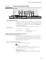
Chapter 6.
6-1
DETAILED CONFIGURATION
Introduction
This chapter describes how to set up configuration items that are initially set on the SRF101/102/103.
Set up configuration items with configuration lock (display number 1 in SYS setup).
If the extended menu is set to ON (display number 2 in SYS setup), you can set up the input range type, recording
scale, recording format, event type and system setup.
Handling Precautions
• You can also set up configuration items during recording. However, if the
range type or other setup items are changed, display and recording
sometimes become temporarily abnormal.
• The Smart Loader Package is needed to set the following functions.
These functions cannot be set on the SRF101/102/103 alone:
• External switch input function assignment extension (factory setting
“ON”)
• Message printing details (factory setting “ON”)
Note
For details on event setting values, chart feed speed and date/time setup to be
configured in menu level 1 with the extended menu “OFF”, see “Chapter 5,
Basic Configuration.”
6-1
Chapter 6. DETAILED CONFIGURATION
6-2
Configuration Data and Factory Settings
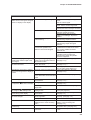
■ Event Setup (individual channels): EVNT
Display
No.
Setup Item
No.1 event setting value
No.2 event setting value
No.1 event type selection
No.1 relay output No.
No.1 event recording ON/OFF
No.2 event type selection
No.2 relay output No.
No.2 event recording ON/OFF
No.1 event differential
No.2 event differential
Setup Description
-19999 to +29999
-19999 to +29999
-, L, H, I, h, L., H.
0 to 6
0 (OFF) / 1 (ON)
-, L, H, I, h, L., H.
0 to 6
0 (OFF) / 1 (ON)
0 to 29999
0 to 29999
*Extened menu
OFF
ON
❍
❍
❍
❍
❍
❍
❍
❍
❍
❍
❍
❍
Factory Setting
0
0
0 (-):OFF
0
1 (ON)
0 (-):OFF
0
1 (ON)
0
0
*: The setup level can be changed by switching the extended menu ON/OFF. For details, see page 6-1.
■ Chart Feed Speed Setup: SPD
Display
No.
Setup Item
Chart feed speed unit
Chart feed speed
Setup Description
0(mm/h)/1(mm/min)
1 to 599(mm/h)/10 to 200(mm/min)
*Extened menu
OFF
ON
❍
❍
❍
❍
Factory Setting
0(mm/h)
40
■ Date/Time Setup: CLK
Setup Item
Setup Description
*Extened menu
OFF
ON
❍
❍
Date
Time (hours:minutes)
❍
❍
Factory Setting
Close to Japan standard time
Close to Japan standard time
■ System Setup 1 (individual channels): SYS (SYS LED lit)
Display
No.
Setup Item
*Extened menu
OFF
ON
0 (OFF)
0 (OFF)
1 (read)
0 to 127
(setting to “0” inhibits communications)
Communications method
1:4800bps, 8bits even parity,1stop bit
2:4800bps, 8bits no parity,2stop bits
3:9600bps, 8bits even parity,1stop bit
4:9600bps, 8bits no parity,2stop bits
Recording format selection
1(trend) / 2(trend+tabulation) /
3(trend+schedule demand)
Recorder ID No.
0 to 99
Recording time ON/OFF
0 (OFF) / 1 (ON)
Scale recording ON/OFF
0 (OFF) / 1 (ON)
Pen phase synchronization setting 1 / 2 / 3
❍
0
❍
1
❍
Schedule demand selection
0 (OFF) / 1 (No.1) / 2 (No.1,2) /
3 (No.1,2,3) / 4 (No.1,2,3,4)
❍
2
(trend+tabulation)
0
1 (ON)
1 (ON)
3(pen phase
synchronization OFF)
0 (OFF)
No.1 schedule demand time
0:00 to 23:59
❍
00:00
No.2 schedule demand time
0:00 to 23:59
❍
00:00
No.3 schedule demand time
0:00 to 23:59
❍
00:00
No.4 schedule demand time
0:00 to 23:59
❍
00:00
0 (OFF) / 1 (ON)
0 (OFF) / 1 (ON)
1 (read) / 2 (read/write)
❍
❍
Factory Setting
❍
❍
❍
Configuration lock
Extended menu entry
Communications access rights
selection
Device address
6-2
Setup Description
❍
❍
❍
❍
Chapter 6. DETAILED CONFIGURATION
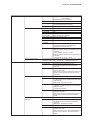
■ System Setup 2 (individual channels): SYS (SYS LED blinks at 1-second intervals)
Display
No.
Setup Item
Setup Description
Recording mode selection
0 (display/recording OFF)
1 (display)
2 (display+recording)
Range code
Selectable from all codes
Input calculation type
1 (PV)/
2 (reference channel-own channel)
3 (own channel- reference channel)
4 (fixed value-own channel)
5 (own channel-fixed value)
Reference channel
1 to 3
Measurement range lower limit
-19999 to +29999
Measurement range upper limit
19999 to +29999
Engineering range decimal point
0 (xxxxx) to 4 (x.xxxx)
Engineering range lower limit
-19999 to +29999
Engineering range upper limit
-19999 to +29999
Fixed value for deviation
-19999 to +29999
PV bias
-19999 to +29999
Engineering unit setting (UNIT) 6 characters
*Extened menu
OFF
ON
Factory Setting
❍
❍
❍
❍
❍
105 (±5V)
1 (PV)
❍
❍
❍
❍
❍
❍
❍
❍
❍
1
1.000
5.000
1 (xxxx.x)
0.0
100.0
0
0
Blank
2 (display+recording)
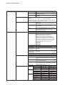
■ System Setup 3 (individual channels): SYS (SYS LED blinks at 2-second intervals)
Display
No.
Setup Item
Scale lower limit
Scale upper limit
Setup Description
-19999 to +29999
-19999 to +29999
*Extened menu
OFF
ON
❍
❍
Factory Setting
0.0
100.0
6-3
Chapter 6. DETAILED CONFIGURATION
6-3
Event Setup
■ Event Setup
CH
EVNT
DATA
EVNT/EVNT
RCD
POC/SPD
DMD
LOCK/CLK
SYS
Channel No. Display No.
1
2
No.1 event type
3*1
selection
1, 2 or 3
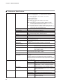
No.2 event type
4*1
selection
5*1
1
6*
Description
No.1 event setting value
No.2 event setting value
No.1 event relay
output No. *2
No.2 event relay
output No. *2
No.1 event differential
No.2 event differential
No.1 event
recording ON/OFF
No.2 event
recording ON/OFF
*1: This is displayed when the extended menu is ON.
Event setting values are not displayed when the event type is set to “–” (event
OFF).
*2: Event setting values that do not support the relay output optional function are
not displayed.
● Setup Details
Event setting value
Event type
: “-19999 to +29999” (U)
: “–” no event
“H” (upper limit)
“L”(lower limit)
“l“ (absolute value deviation lower limit)
“h” (absolute value deviation upper limit)
“L.” (rate-of-change lower limit)
“H.” (rate-of-change upper limit)
• Definition of “absolute value deviation”
Absolute value deviation =
| own channel PV (actual PV before input calculation) - fixed value (event
setting) |
where,
Event setting value
: Used for setting the fixed value
Differential
: Used as the setting value of the absolute value
deviation
Differential gap
: Fixed at 10 U
• Definition of “rate-of-change”
Rate-of-change =
Change ∆PV in a cycle (set by differential, unit: seconds) having PV input is
judged as being either larger or smaller than the event setting value. Changes in
PV midway are ignored.
where,
Differential setting value : Used for setting the judgment cycle
Differential gap
: Fixed at 10 U*
Relay output No.
: “0 to 6” (“0” relay output OFF, “1 to 6” can be set
only when relay output is supported as an optional
function)
Event recording ON/OFF : “0” event recording OFF
“1” event recording ON
Event differential
: “0 to 29999” (U)
Note
*10 U = 10 times the minimum setting resolution. The “minimum setting resolution” is
the resolution according to the engineering range number of digits past the decimal
point. For example, when the number of digits past the decimal point is set to
“XXX.XX” the minimum setting resolution will be “0.01”.
6-4
Chapter 6. DETAILED CONFIGURATION
■ Description of Event Setup Items
● Event type and operation
! "#$ !! %
Event type “h” (absolute value deviation upper limit)
PV0 (value before PV bias)
10U
"#
OFF
OFF
Deviation
Event occurrence condition
Event reset condition
ON
ON
OFF
H=| PV0-S |
HD
H<D-10 U
'( )
*+ , (( -.
* * * ≤
!" #
&* +,-. / 0 %1
! " ≤
$% &' ( )
Differential setting value
= absolute value deviation
Event setting value
Differential setting value "#
= absolute value deviation
10U
ON
!"# $ %
#
$%
&% #
≤'
(') ! " # $% &
Handling Precautions
The rate-of-change event compares the amount of change with the setting
value at each judgment cycle that is preset as shown above. Accordingly,
the event sometimes does not turn ON according to the timing of the
judgment cycle even if a PV rate-of-change likely to the turn the event ON
occurs.
6-5
Chapter 6. DETAILED CONFIGURATION
● Event relay No.
Output to all relays is disabled when the event relay No. is set to “0”. Two events
can be set to a single channel. The same event relay No. can be set to different
channels. In this case, the relay that is used in duplicate is OR-ed and cannot be
AND-ed.
Handling Precautions
Event relay Nos. other than “0” can be set only when relay output
(optional function) is supported.
● Event recording ON/OFF
When event recording is set to OFF, neither event occurrences nor resets are
recorded.
● Event buffer
Up to 48 events including occurrence and resets can be buffered.
● Relay excitation direction and contact
The coil of the specified relay is excited when an event occurs. The contact is
transfer contact output (both NO and NC contacts are output by SPDT output).
● Relay contact rating
• 100Vac, 0.2A (non-inductive load), 30Vdc, 0.3A (non-inductive load)
• Minimum load: 10mVdc, 10µA
• Electrical life: 100,000 operation (resistive load)
6-6
Chapter 6. DETAILED CONFIGURATION
6-4
Chart Feed Speed Setup
■ Chart Feed Speed Setup
CH
EVNT
DATA
EVNT/EVNT
RCD
POC/SPD
DMD
LOCK/CLK
SYS
Channel No. Display No.
1
Description
Chart feed
speed unit
Chart feed speed value
Handling Precautions
• When pen phase synchronization is carried out on a 2- or 3-pen model, the pen
synchronization memory is cleared when the chart feed speed is changed. When
this happens, the No.1 and No.2 pens stand by at the left edge at the start time
position of the No.3 pen. For details of pen synchronization, see “● About pen
synchronization” (page 6-10).
• Characters are not printed when the chart feed speed is 151 mm/h or more.
● Setup Details
Chart feed speed unit
Chart feed speed value
: “0” (mm/h)
“1” (mm/min)
: “1 to 599” (when unit is set to mm/h)
“10 to 200” (mm/min)
■ Description of Chart Feed Speed Setup Items
● Chart feed speed and printing cycle
The time reference for the tabulation printing cycle is “00:00”. The tabulation
interval on the chart paper is 40 mm. If, for example, the chart feed speed is 20
mm/h, then the tabulation time becomes 00:00, 02:00 and so forth up to 22:00.
To carry out tabulation printing at a specific time, select “trend + schedule
demand” printing as the recording format.
● Chart feed speed and date printing
Chart feed speed and date are printed alternately.
Note
Chart Feed Speed and Character Size
Characters are expressed as a 5 x 7 dot matrix, and are 1.2mm wide. Their
vertical length varies according to the chart feed speed.
Handling Precautions
Characters are not printed when the chart feed speed is 151mm/h or
more.
6-7
Chapter 6. DETAILED CONFIGURATION
6-5
Date/Time Setup
■ Date/Time Setup
CH
EVNT
DATA
EVNT/EVNT
RCD
POC/SPD
DMD
LOCK/CLK
SYS
Year
Month
Hour
Date
Minute
Handling Precautions
If the date and time setup is in error, all data blinks when you press the
ENT
key. If this happens, press any key to redisplay the data entry
display.
The number of seconds in the time setup are reset (so that counting
ENT
starts from “00”) when you press the
key only when the numerical
values for the time setup are changed. If you press the ENT key
without making any changes to the numerical values for the time setup,
the date setup display will be redisplayed, and the number of seconds
will not be reset.
● Setup Details
Year
Month
Day
Hour
Minute
: “00 to 99”(Last two digits of year)
: “01 to 12” January to December
: “01 to 31” 1st to 31st
: “00 to 23” 0 am to 11 pm
: “00 to 59” 0 to 59 minutes
Note
• Clock accuracy is about ±50ppm or about 130seconds/month under standard
conditions.
• The SRF101/102/103 automatically adjusts for leap years until 2099.
6-8
Chapter 6. DETAILED CONFIGURATION
6-6
System Setup 1 (Basic Setup)
■ System Setup 1 (SYS LED is lit continuously)
CH
EVNT
DATA
EVNT/EVNT
RCD
POC/SPD
DMD
LOCK/CLK
SYS
Channel No. Display No.
1
2
3 *2
4 *2
5 *1
6 *1
7 *1
8 *1
9 *1
A *1
B *1
C *1
D *1
E *1
Description
Configuration
lock
Extended menu
ON/OFF
Communications
access rights
Device address
Recording format
Recorder ID No.
Recording time
ON/OFF
Scale recording
ON/OFF
Pen phase
synchronization
selection
Schedule
demand
ON/OFF
No.1 schedule demand (hours)
No.2 schedule demand (hours)
No.3 schedule demand (hours)
No.4 schedule demand (hours)
Communications
method
No.1 schedule demand (minutes)
No.2 schedule demand (minutes)
No.3 schedule demand (minutes)
No.4 schedule demand (minutes)
*1: This is displayed when the extended menu is ON.
*2: These are not displayed on models that do not support communications
(optional function).
Handling Precautions
When the configuration is locked, setups can be confirmed but not changed.
● Setup Details
Configuration lock
: “0” (OFF: disabled)
“1” (ON: enabled)
Extended menu ON/OFF
: “0” (OFF)
“1” (ON: enabled)
Communications access rights
: “1” (read only)
“2” (read/write)
Device address
: “0 to 127” (communications is inhibited
when set to “0”.)
Communications method
: “1” (4800 bps, 8 bits, even parity, 1 stop bit)
“2” (4800 bps, 8 bits, no parity, 2 stop bits)
“3” (9600 bps, 8 bits, even parity, 1 stop bit)
“4” (9600 bps, 8 bits, no parity, 2 stop bits)
Recording format
: “1” (trend)
“2” (trend + tabulation)
“3” (trend + schedule demand)
Recorder ID No.
: “0 to 99” (ID No. is not printed when set to
“0”)
Time recording ON/OFF
: “0” (OFF: time is not recorded)
“1” (ON: time is recorded)
Scale recording ON/OFF
: “0” (OFF: scale is not recorded)
“1” (ON: scale is recorded)
Pen phase synchronization selection : “1” (All pens are compensated referenced to
the printing pen.)
“2” (All pens are compensated referenced to
the reference pen.)
“3” (Pen phase is not compensated.)
6-9
Chapter 6. DETAILED CONFIGURATION
Schedule demand ON/OFF
: “0” (Printing is not carried out at any
preset time.)
“1” (Tabulation printing is carried out at
the No.1 time.)
“2” (Tabulation printing is carried out at
the No.1 and No.2 times.)
“3” (Tabulation printing is carried out at
the No.1, No.2 and No.3 times.)
“4” (Tabulation printing is carried out at
all No.1, No.2, No.3 and No.4 times.)
Schedule demand hours:minutes setting : “0 to 23” (hours)
“0 to 59” (minutes)
■ Description of System Setup 1 Items
● How to use the recorder ID No.
When you are using two or more SRF101/102/103s, you can print individual
recorder ID Nos. when printing is started to distinguish which recorder is being
used to record on the chart.
The recorder ID No. is not used for applications other than printing.
● About time recording OFF
When time recording is set to OFF, no date/time information is printed on the
chart. To give priority to real-time recording, leave the time recording setup to
“ON” (factory setting).
● About pen phase compensation (POC)
The difference (phase) between the positions of the printing pen and the trend
recording pens can be matched (synchronized) using the memory function so that
recording is carried out without any phase difference between the pens on the time
axis on the chart.
Display is carried out in real time at all times regardless of the pen phase
synchronization setting.
“1” The phases of all printing pen and trend recording pens are synchronized.
The printing pen is referenced to time. The trend recording pens operate
delayed by the difference in mechanical positions with the printing pen.
Accordingly, all trend recording pens operate with a delay after actual PV
movement.
The time line is printed as “
”.
“2” The phases of all printing pen and trend recording pens are synchronized,
however the reference pen of the trend recording pens will be referenced to
time. (On 1-pen models, this is the No.1 pen; on 2-pen models, this is the
No.2 pen; and on 3-pen models, this is the No.3 pen.)
Accordingly, only the standard pen operates together with actual PV
movement.
The printing pen operates first to print the time. The time line is printed as
“
”.
“3” The phase of the trend recording pens is not compensated.
Accordingly, the recording results will no longer be synchronous. However,
all trend recording pens operate together with actual PV movement, and the
time line is not printed.
6-10
Chapter 6. DETAILED CONFIGURATION
Handling Precautions
If the chart feed speed is changed while the pen phase is being
synchronized, all data stored in memory so far will be cleared, and trend
pens other than the reference pen will move to the left edge.
● Distance between pens (pen tips)
Between printing pen and No.3 pen:
About 4.9mm
Between No.3 pen and No.2 pen, and No.2 pen and No.1 pen: About 3.3mm
No.1 pen
Direction of chart feed
No.2 pen
No.3 pen
Printing pen
Printing pen
No.3 pen
No.2 pen
No.1 pen
4.9 mm
3.3 mm
3.3 mm
Platen
● Schedule demand
When “trend + schedule demand” recording is selected as the recording format,
and steps B to E in the setup procedure are set, tabulation can be recorded at the
necessary times up to four times per day.
If schedule demand is set, and the SRF101/102/103 is set to a recording state,
recording will be carried out without any omissions, for example, when recording
processes that require recording at fixed times, or when recording process values
at the change of operator shifts.
6-11
Chapter 6. DETAILED CONFIGURATION
6-7
System Setup 2 (Range Setup)
■ System Setup 2 (SYS LED blinks at 1-second intervals)
This is displayed when the extended menu is ON.
CH
EVNT
DATA
EVNT/EVNT
RCD
POC/SPD
DMD
LOCK/CLK
SYS
Description
Channel No. Display No.
Recording mode
1*1
Range code
2*1
Input calculation
3*1
type
4*1 Reference channel
5*1
Measurement range lower limit
1, 2 or 3
6*1
Measurement range upper limit
Engineering
7*1
range decimal
point position
8*1
Engineering range lower limit
9*1
Engineering range upper limit
A*1
Fixed value for deviation
B*1
PV bias
C*1
Character order
UNIT (character code)
*1: When the range code has been changed, the display will be initialized
to match the range code.
Handling Precautions
Some items are not displayed depending on the setup details such as
range code or input calculation type.
● Setup Details
Recording mode
: “0” (display/recording OFF)
“1” (display only)
“2” (display+recording)
Range code
: See “6-9 Range Code Table” (page 617)
(example: 230 → thermocouple/-200.0
to +1370.0°C)
Input calculation type
: “1” (PV value)
“2” (reference channel - own channel)
“3” (own channel - reference channel)
“4” (fixed value - own channel)
“5” (own channel - fixed value)
Reference channel
: “1 to 3” (Select reference channel to be
used for calculating the channel
Measurement range upper/lower limits : “-19999 to +29999” (U) (For details on
the decimal point position of the
measurement range, see “6-9 Range
Code Table” (page 6-17).
Engineering range decimal point
: “0 to 4"
(0 → XXXXX, 1 → XXXX.X, 2 →
XXX.XX ...)
Engineering range upper/lower limits : “-19999 to +29999” (U)
Fixed value for deviation
: “-19999 to +29999” (U)
PV bias
: “-19999 to +29999” (U)
Character order
: “1 to 6” (change by ENT key)
UNIT (Engineering unit)
: See
“6-10 Character Code Table”
(page 6-19)
6-12
Chapter 6. DETAILED CONFIGURATION
■ Description of System Setup 2 (Range Setup)Items
● Recording mode and operation
Recording Mode
“0” OFF Operable
Input Processing
Event
Recording
X
X
X
“1” display only
Operable
Operable
X
“2” display/recording
Operable
Operable
Operable
Recording modes 1 and 2 are operable even when recording is OFF.
● Range code selection
The SRF101/102/103 supports full multi-input. Merely selecting the range type
here fixes the range code.
● Details of input calculation type
“2”: {(reference channel raw PV value)+(reference channel bias value)}-{(own
channel raw PV value)+(own channel bias value)}
“3”: {(own channel raw PV value)+(own channel bias value)}-{(reference channel
raw PV value)+(reference channel bias value)}
“4”: (fixed value)-{(own channel raw PV value)+(own channel bias value)}
“5”: {(own channel raw PV value)+(own channel bias value)}-(fixed value)
● Input calculation type and calculation result
The calculation result is displayed as the data of the own channel, and recording
and event processing is carried out.
● Position of engineering range decimal point and engineering range upper/lower limit
values
These settings determine the display resolution of the measurement range. The
resolution of trend recording is fixed to 1/2000 regardless of these settings.
● About reverse scaling
Reverse scaling can be set so that the minimum and maximum numerical values
for the lower and upper limit values in both the measurement range and
engineering range are inverted.
6-13
Chapter 6. DETAILED CONFIGURATION
● About measurement range and engineering range setup
These items must be set in the case of input range codes 100, 101, 102 and 105.
(When other range codes are set, the setup mode is not migrated to.)
PV is calculated by the following formula:
(engineering range upper limit value) - (engineering range lower limit value)
(PV)=
x {(input value) -
(measurement range upper limit value) - (measurement range lower limit value)
(measurement range lower limit value)} + (engineering range lower limit value) + (PV bias)
[Setup Example 1]
Indicated PV value when 2V is input = 625.0kPa
Item
Range code setting
Measurement range upper value
Measurement range lower value
Engineering range upper value
Engineering range lower value
Engineering unit
Input Value
105
5.000
1.000
Description
-5 to +5V
When 0.0 to 2500.0kPa is assigned to
the voltage input value of 1 to 5V.
2500.0
0.0
kPa
[Setup Example 2]
Indicated PV value when 2V is input = 0.0kPa
6-14
Item
Range code setting
Measurement range upper value
Measurement range lower value
Input Value
105
3.200
1.200
Engineering range upper value
Engineering range lower value
PV bias
Engineering unit
2500.0
0.0
-1000.0
kPa
Description
-5 to +5V
When 0.0 to 2500.0kPa is assigned to
the voltage input value of 1.2 to 3.2V.
Chapter 6. DETAILED CONFIGURATION
6-8
System Setup 3 (Scale Setup)
■ System Setup 3 (SYS LED blinks at 2-second intervals)
This is displayed when the extended menu is ON. (System setup 3 cannot be set
unless the extended menu is ON.)
CH
EVNT
DATA
EVNT/EVNT
RCD
POC/SPD
DMD
LOCK/CLK
SYS
Description
Scale lower limit value
Scale upper limit value
Channel No. Display No.
*1
1, 2 or 3
*2
*: When the range code has been changed, the display will be initialized
to match the range code. (In system setup 3, the scale lower and upper
limit values are initialized to match the new range code, if the range
code of system setup 2 is changed.)
Handling Precautions
The decimal point position of the scale is fixed.
Thermocouple, RTD input:
See “6-9 Range Code Table” (page 6-15)
mV, V input:
Refer to the engineering range decimal point position in system setup 2.
● Setup Details
Scale upper/lower limits
: “-19999 to +29999” (U)
■ Description of System Setup 3 Items
● About reverse scaling
Reverse scaling can be set so that the minimum and maximum numerical values
for the lower and upper limit values are inverted.
(example)
Lower limit value becomes “+100.0” and upper limit value becomes “-100.0”.
● Minimum scaling range
Trend recording becomes stepped if scaling is set too narrow.
The resolution of trend recording in a 100 mm recording width is 1/2000.
Referring to “9-2 Input Types, Ranges and Display Accuracy” (page 9-5), set
scaling so that a resolution higher than this is obtained.
6-15
Chapter 6. DETAILED CONFIGURATION
● About scale setup
The recording scale lower and upper limit values are set as the chart 0% and 100%
positions. For example, the range is -200.0 to +1370.0°C (input range code: 230)
in the case of a K thermocouple. However, to set the left side (0% position) of the
chart as “0.0°C” and the right side (100% position) of the chart as “1000.0°C”
when carrying out trend recording on the chart, set the scale lower limit value to
“0.0” and the upper limit value to “1000.0”.
As the scale setup range is -19999 to +29999, this can be used to record specific
zones. For example, in the above example, to write the trend of a K thermocouple
on the right half of the chart, set the scale lower limit value to “-1000.0” and the
upper limit value to “1000.0”.
[Example] K thermocouple Range code: 230 (-200.0 to +1370.0°C)
!
!
& !
$ $ ! %
& " #
Handling Precautions
The scale setup range is -1999.9 to +2999.9.
6-16
!
Chapter 6. DETAILED CONFIGURATION
6-9
Range Code Table
Input
Type
DC voltage
Thermocouple
Range
Symbol
mV
Code
mV/V input
mV/V indication range
100
±14.00 mV
-19999 to +29999
101
±25.00 mV
-19999 to +29999
102
±70.00 mV
-19999 to +29999
V
105
±5.000 V
-19999 to +29999
R
200
0.0 to
1760.0°C
S
210
B
220
0.0 to
1820.0°C
K
230
-200.0 to +1370.0°C
231
-200.0 to
+600.0°C
232
-200.0 to
+300.0°C
240
-200.0 to
+900.0°C
241
-200.0 to
+350.0°C
250
-200.0 to +1100.0°C
251
-200.0 to
+450.0°C
260
-200.0 to
+400.0°C
261
-200.0 to
+250.0°C
270
0.0 to
1300.0°C
271
0.0 to
700.0°C
272
0.0 to
350.0°C
WRe0-26 280
0.0 to
2320.0°C
0.0 to
2320.0°C
E
J
T
N
WRe5-26 290
PL II
310
-100.0 to +1390.0°C
311
-100.0 to
+600.0°C
312
-100.0 to
+300.0°C
Ni-Ni•Mo
320
0.0 to
1310.0°C
Resistance temperature Pt100 Ω
401
-200.0 to
+300.0°C
detector (RTD)
402
-140.0 to
+150.0°C
403
-140.0 to
+100.0°C
JPt100 Ω 411
-200.0 to
+300.0°C
412
-140.0 to
+150.0°C
413
-100.0 to +100.0°C
6-17
Chapter 6. DETAILED CONFIGURATION
Type
Thermocouple
Symbol
Code
R
500
S
510
B
520
K
530
-328 to +2498°F
531
-328 to +1112°F
532
-328 to
540
-328 to +1652°F
541
-328 to
E
J
T
N
32 to
3200°F
32 to
3308°F
+572°F
+662°F
550
-328 to +2012°F
551
-328 to
+842°F
560
-328 to
+752°F
561
-328 to
+482°F
570
32 to
2372°F
571
32 to
1292°F
572
32 to
662°F
WRe0-26 580
32 to
4208°F
32 to
4208°F
WRe5-26 590
PL II
6-18
°F Range
610
-148 to+2534°F
611
-148 to+1112°F
612
-148 to
+572°F
Ni-Ni•Mo
620
32 to
2390°F
Resistance temperature Pt100 Ω
701
-328.0 to
+572.0°F
detector (RTD)
702
-220.0 to
+302.0°F
703
-148.0 to
+212.0°F
JPt100 Ω 711
-328.0 to
+572.0°F
712
-220.0 to
+302.0°F
713
-148.0 to
+212.0°F
Chapter 6. DETAILED CONFIGURATION
6 - 10
Character Code Table
Upper
Lower
0
2
3
4
5
6
7
8
(blank) 0
@
P
`
p
3
°
1
!
1
A
Q
a
q
2
"
2
B
R
b
r
3
#
3
C
S
c
s
4
$
4
D
T
d
t
5
%
5
E
U
e
u
6
&
6
F
V
f
v
7
'
7
G
W
g
w
8
(
8
H
X
h
x
9
)
9
I
Y
i
y
A
✽
:
J
Z
j
z
B
+
Ω
;
K
[
k
<
L
\
l
-
=
M
]
m
µ
E
.
>
N
^
n
2
F
/
?
O
_
o
C
D
`
°
•
2
Setup Example:kPa
Step
Engineering Unit
Character Code
1
k
6B
2
P
50
3
a
61
4
(blank)
20
5
(blank)
20
6
(blank)
20
6-19
Chapter 6. DETAILED CONFIGURATION
6 - 11
External Switch Inputs (Optional Function)
The following functions are set to external switch inputs before the SRF101/102/103 is shipped from the factory.
These functions cannot be changed on the SRF101/102/103 alone. You can, however, set any of the following
functions using the Smart Loader Package (SLP-F10) and the program data card for the SRF101/102/103:
Default function assignments:
RSW1 recording start/stop
RSW2 demand printing
RSW3 chart feed
RSW4 print message 1
Recording is started by OPEN → CLOSE.
Recording is stopped by CLOSE → OPEN.
Demand printing is started by OPEN → CLOSE.
Chart is fed 40 mm by OPEN → CLOSE.
Printing (MSG1) is started by OPEN → CLOSE.
The following functions can be selected by using the Smart Loader Package (SLP-F10):
Recording start/stop
Demand printing
Chart feed
Print message 1
Print message 2
Print message 3
Print message 4
Recording is started by OPEN → CLOSE.
Recording is stopped by CLOSE → OPEN.
Demand printing is started by OPEN → CLOSE
Chart is fed 40 mm by OPEN → CLOSE.
Printing is started by OPEN → CLOSE.
Printing is started by OPEN → CLOSE.
Printing is started by OPEN → CLOSE.
Printing is started by OPEN → CLOSE.
Handling Precautions
• Maintain external switch input ON/OFF states for at 500 ms or more.
• To prevent malfunction caused by noise, changes in state are not
detected unless they last for 500 ms or more.
Contact CLOSE
Time
Contact OPEN
500 ms 500 ms
500 ms 500 ms
Required time
Required time
Recording start
6-20
Recording stop
Chapter 6. DETAILED CONFIGURATION
6 - 12
Printing of Messages
Message printing functions when the SRF101/102/103 supports external switch inputs (optional function).
Message printing is started up by external switch input.
By message printing, the time (hours:minutes) and message (up to six characters) are printed.
To change the details set to a message, you will need the Smart Loader Package (SLP-F10). The following table
shows factory settings:
Message No. Printed Details
1
MSG1
2
MSG2
3
MSG3
4
MSG4
You can set any message you like up to six characters long using the Smart Loader
Package (SLP-F10). Set the message referring to “6-10 Character Code Table”
(page 6-18).
6-21
Chapter 6. DETAILED CONFIGURATION
6 - 13
About Input Filter Function
The function of input filter is to display and record with the input value which is the value of moving average of
the values (1 second) measured in the past 8 times at 125ms intervals.
The factory setting is set to ON.
The setup change cannot be made from the display setup unit.
When changing the setup, the SLP-F10 Smart Loader Package is needed.
6-22
Chapter 6. DETAILED CONFIGURATION
6 - 14
About Digital Printing Priority
Digital printing on the SRF101/102/103 is subject to several restrictions to ensure that trend recording is not
interrupted. This is called “printing control.” The following briefly describes printing control:
■ Printing Control during a Print Conflict
Digital printing is categorized into the below four groups. In principle, printing is
carried out in the order in which it occurs within each group. However, start of
printing is sometimes suppressed or printing is canceled midway according to the
type of printing. If printing of one group conflicts with printing of another, either
printing of one of the groups is suppressed or one of the groups is printed over the
other. The following describes these restrictions.
Print Group
Print Item
A
Event
B
Initial printing
Restrictions
Demand
Message
Schedule demand Printing is canceled when demand printing occurs
(even during print standby).
Tabulation
Scale
Printing of this item is not started up when other
printing is currently in progress or standing by.
Channel No.
Printing of this item is not started up when other
printing is currently in progress or standing by.
Handling Precautions
• Printing is canceled when printing conflicts with the scale upper limit
and the TAG/UNIT and A or D of the scale.
• When two or more schedule demands are registered, and schedule
demand printing is currently in progress or standing by, startup of the
remaining schedule demand is not accepted even if the startup time
is reached.
■ Simultaneous Printing Control
When demand printing and message printing or schedule demand printing and
message printing continuously stand by to be printed, a message is printed on the
hours:minutes line of demand printing (manual demand and schedule demand).
This, however, does not apply in the following instances:
• When message printing is started during demand printing (or, vice versa)
• When demand printing (or, message printing) is started anew in a simultaneous
printing state
6-23
Chapter 6. DETAILED CONFIGURATION
6 - 15
ON/OFF of the Reference Junction Temperature Compensation
WARNING
Be sure to turn the power source OFF before changing the DIP switch
setting.
Failure to do so might cause electric shock.
CAUTION
Be sure to remain the other settings of the DIP switch the same as the factory
setting.
Doing so might cause faulty operation.
For the thermocouple inputs, the reference junction compensation is normally performed internally.
If it is necessary to compensate externally, the internal compensation can be deactivated by changing the setting of
the DIP switch SW1.
Handling Precautions
Once setting is made, it is effective on all the inputs. No exception can be
made for any specific input only.
■ Place of the DIP switch
Remove the chart cassette.
>>You can find the DIP switch (SW1) at the bottom of the internal unit.
Factory Setting
SW1
No.
ON
1
2
3
4
5
6
7
8
1
2
3
4
5
6
7
8
position OFF OFF OFF OFF OFF OFF ON ON
ON :Deactivates internal compensation.
OFF :Activates internal compensation.
■ Setting the DIP switch
Change the No. 1 switch of the DIP switch (SW1) ON.
SW1
ON
1
6-24
2
3
4
5
6
7
8
Chapter 7.
7-1
MAINTENANCE
Periodic Inspection
To ensure prolonged use of the SRF101/102/103, periodically inspect the operating status of the SRF101/102/103 and
maintain it in a proper working condition. Perform the following inspections, and replace consumables and maintenance parts as
required:
Inspection Item
Remedy
See page
Faint recording or Replace the pen when recording is faint.
printing
Trend pen life:
Approx. 1,200m
Printing pen life: Approx. 80,000 characters
4-1
Incorrect feeding Re-load the chart.
of chart, paper jam
4-1
Insufficient
remaining chart
4-1
The remaining amount of chart is printed at 10 cm
intervals on the right side of the chart. When only 60 cm of chart remains,
the remaining chart warning is printed on the chart.
Lubrication of pen Replace with new chart.
spindles
Lubricate the spindles with one or two drops of lubricating oil once every six months.
Lubricate the printing pen and trend pen spindles, and the four spindles on the 3-pen
model.
After lubricating the spindles, lightly wipe the lubricating oil with a clean, dry cloth.
-
Handling Precautions
• Before lubricating, be sure to turn the power OFF.
• Before lubricating, wipe the spindle with a clean, dry cloth to wipe off any dirt.
Recommended product: Kim Wipe® made by Crecia Co., Ltd.
• Lubricate only the spindles. Never lubricate other parts.
• Avoid forcibly moving pen holders to the left or right by hand.
Drive scale
Spindle
Pen holder
Lubrication point
When dust is
collecting on the
door window
Lubrication point
Wipe dust from the door window using soft dry cloth or paper.
-
Handling Precautions
Never wipe the door window with paint thinner or other organic solvents.
Doing so might cause the window to crack or cloud.
7-1
Chapter 7. MAINTENANCE
Measuring the Display Accuracy of Analog Inputs
7-2
This section describes how to measure the display accuracy of analog inputs. We recommend measuring the
display accuracy of analog inputs once every year to ensure appropriate use of the SRF101/102/103.
If, as a result of measurement, it is found that accuracy deviates from the specified display accuracy of the
SRF201/202/203, perform one-point adjustment using the PV bias. If the SRF101/102/103 needs to be calibrated,
contact your dealer.
Note
For details on display accuracy, see “9-2 Input Types, Ranges and Display
Accuracy” (page 9-5).
For details on PV bias, see “6-7 System Setup 2 (Range Setup)” (page 6-12).
■ Equipment Required for Measurement
The standard display accuracy of the SRF101/102/103 is 0.15%. When
measuring the standard display accuracy, use equipment having an accuracy
higher than this.
• DC standard voltage generator: When measuring DC voltage and thermocouple
inputs
• Standard contact compensator (icebox): When measuring thermocouple inputs
• Dial variable resistor: When measuring resistance temperature detectors (RTD)
■ Measurement Environment
The standard display accuracy of the SRF101/102/103 is based upon the
standard conditions listed in “9-2 Input Types, Ranges and Display Accuracy”
(page 9-5). These conditions must also be satisfied when measuring the accuracy
of analog inputs. If accuracy is measured outside of these conditions, the following
additional accuracies must be included in the display accuracy measurement:
● Additional accuracies
(ambient temperature characteristics)
• Indication and recording fluctuations in response to temperature changes
of±10°C:
(excluding standard contact temperature compensation error at thermocouple
input)
Indication fluctuation: Within ±(0.1% F.S. + resolution x 2)
Recording fluctuation: Within (display fluctuation) + (0.5% F.S.)
(excluding influence of chart expansion/shrinkage)
(ambient humidity characteristics)
• When humidity changes from 60% to 85%RH:
Indication fluctuation: Less than ±0.1% F.S.
• When humidity changes from 60% to 45%RH:
Indication fluctuation: Less than ±0.1% F.S.
7-2
Chapter 7. MAINTENANCE
■ Procedure
• Wire to each of the input types as shown in the figure on the right, and warm up
the SRF101/102/103 for at least 60 minutes.
• Make sure that the ambient temperature, humidity and other environmental
conditions are within their respective standard conditions.
• Apply inputs equivalent to 0% and 100% of the input range, read the indications
at this time, and measure the error from the difference with the input values.
● When measuring DC voltage
DC standard voltage generator
+ -
G
1
2
3
Input terminals
● When measuring a thermocouple
DC standard voltage generator
+
- G
Copper wire
1
2
3
Thermocouple
+ - + - bare lead
Input terminals
Reference contact compensator (ice box)
● When measuring a resistance temperature detector
1
2
3
Dial variable resistor
3b
2b
Set the resistance of
all three leads to same value.
Input terminals
1b
7-3
Chapter 8.
8-1
TROUBLESHOOTING
Error Displays and Descriptions of Errors
The SRF101/102/103 is provided with a self diagnostics function that inspects the functions at all times. If an
error has occurred, an error code is displayed on the display.
If two or more errors have occurred simultaneously, error codes are displayed successively from the lowest number
upwards.
To cancel an error code display, remedy the error according to the following tables, and then turn the power OFF
then ON again:
If an error code stays displayed even though a remedy has been carried out, contact your dealer for repair.
CH
Error code
Diagnostic item
EVNT
DATA
EVNT/EVNT
RCD
POC/SPD
DMD
LOCK/CLK
SYS
Description
Operation
Remedy
Trend pen
error
The control unit of one Recording can be
or more trend pens is in continued using
error.
normal pens.
Contact your dealer for repair.
Printing pen
error
The printing pen origin
cannot be detected.
The origin is detected
each time that printing
is carried out. If the
origin can be detected,
printing is resumed,
and trend recording can
be carried out normally.
Check the printing pen or holder
to see if any object is contacting
or nipped by the pen or holder.
If you cannot remedy this trouble,
contact your dealer for repair.
Battery error
The battery for clock
backup is worn.*
• Date and time are reset Contact your dealer for repair.
to “98/01/01” and “00:00”
respectively.
• All indications other than
the clock display are
carried out normally.
A/D error
A/D conversion is not
carried out correctly.
• Data indication is “
• Recording exceeds
upper limit.
” Contact your dealer for repair.
* :Battery life is about 10 years when the recorder is operated for 8 hours per day within
temperature range of 0 to 40°C.
Handling Precautions
is omitted from the above table.
8-1
Chapter 8. TROUBLESHOOTING
8-2
Remedying Trouble
Trouble
Probable Cause
Remedy
No operation (e.g. display, recording) Power is not being supplied to the Check the wiring and power voltage, and
body.
supply the power correctly.
The power switch on the body is
OFF.
Set the power switch at the bottom right
on the body to ON.
The fuse has blown.
Contact your dealer for repair.
Note 1: A probable cause is a damaged cable or connector between the chassis
and body case.
Trouble
DISP
Pressing the
key does not
advance the display to PV value
display.
Probable Cause
Remedy
The recording mode for all channels Set the recording mode for the required
is set to “display/recording OFF”. channels.
Although AUTO is displayed, the PV Only one channel can display.
value of each channel does not
successively display automatically.
Set the recording mode for the required
channels.
The PV value is displayed only for a
specific channel.
(The decimal point of channel blinks.)
DISP
The PV value is displayed only for a [MAN] display mode is selected. Press the
key and select the
specific channel.
AUTO display mode.
(The decimal point of channel goes out.)
“ALXX” is displayed on the display.
An error was discovered during
self diagnostics.
Follow the remedy described on page 8-1.
Recording is not carried out even
though PV value display is normal.
The recording mode for all
channels is set to “display only”.
Set the recording mode for the required
number of channels.
Recording is not ON.
Press the
The pen cartridge has reached
the end of its life.
Replace with a new pen cartridge.
(See page 4-4.)
The pen cartridge is not loaded.
Attach the pen cartridge. (See page 4-4.)
RCD
key to start recording.
The chart cassette is not attached Push the cassette in as far as possible,
correctly.
and press the load lever.
Digital printing is not carried out.
The printing pen has reached
the end of its life.
Replace with a new pen cartridge.
(See page 4-4.)
The printing pen is not loaded
correctly.
Correctly load the printing pen.
(See page 4-4.)
A chart speed at which digital
printing is carried out is set.
Set the chart printing speed to 150
mm/h as necessary. (See page 4-4.)
Faint recording color
The pen has reached the end of
its life.
Replace with a new pen. (See page 4-4.)
The chart is not being fed.
The chart cassette is not
attached correctly.
Make sure that the chart holder spring
and chart guide are correctly
attached in place. Attach correctly
if necessary. (See page 4-1.)
The chart has come loose from the
The chart cassette is not
Make sure that the chart holder spring
8-2
Chapter 8. TROUBLESHOOTING
Trouble
Probable Cause
Remedy
“OL”, “-OL”, “OF” or “-OF” is displayed An excessive voltage is being input. Make sure that the signal voltage is
Make sure that the signal voltage is
correct.
at the PV display on the display.
Enter the correct signal.
Make sure that the signal voltage is
correct. Set the correct range code.
Check the polarities of the input
terminals, and wire correctly if necessary.
The wiring or sensor is broken.
Check the wiring from the sensor for
breakages. Repair the sensor.
Check the wiring from the signal
oscillator for breakages. Repair the
oscillator.
The sensor or signal generator is Make sure that the sensor is not
malfunctioning.
malfunctioning. Repair the sensor.
Make sure that the signal generator is not
malfunctioning. Repair the signal
generator.
The input impedance of equipment Make sure that the equipment connected
connected in parallel to the
in parallel to this recorder is not turned
SRF101/102/103 has dropped.
OFF. Turn the parallel-connected
equipment ON.
Make sure that the equipment connected
in parallel to this recorder is not
malfunctioning. Repair the parallelconnected equipment.
PV values using engineering scaling The engineering range upper limit Set the correct engineering range.
remain fixed values in spite of the
value is set to the same value as (See page 6-14.)
input signal.
its lower limit value.
The PV display shows an error with The range code setting does not Set the correct range code.
the actual PV value.
match the sensor.
(See page 6-17.)
The PV bias is inappropriate.
Set the appropriate PV bias. Todisable,
set to “0” (zero). (See page 6-12.)
Recording is 0% or less or 100% or The scale setting is inappropriate. Set the scale matched to the input.
more even though the PV display is
(See page 6-15.)
correct.
The scale upper limit value is set Set the correct scale. (See page 6-15.)
to the same value as its lower limit
value.
Trend is stepped
The scale span is far smaller than Set the scale as required.
the resolution.
(See page 6-15.)
Pressing the ENT key in the
Configuration is locked.
Cancel the configuration lock.
configuration mode cannot set data.
(See page 5-3.)
An attempt was made to enter
Enter data in the correct entry range.
illegal data.
Pressing the SET key does not enter The extended menu ON/OFF
Set the extended menu ON/OFF setting
the range or scale setting mode.
setting is OFF.
to ON. (See page 5-3.)
The recorder does not enter the
The event type setting is set to
Correct the event type setting.
event setting value display.
“event OFF”.
(See page 6-4.)
The setting value of the event relay The event relay optional function Attach the add-on optional unit if
No. does not light.
is not supported.
necessary. (See page 1-3.)
The optional unit is malfunctioning. Repair
Events are not recorded on the chart. The event recording ON/OFF
Set the event recording ON/OFF
setting is set to “event recording setting to “event recording ON”
OFF”.
(See page 6-4.)
The event switches ON/OFF
The event differential is too small. Set the event differential to the
continuously.
appropriate value. (See page 6-4.)
Characters are not printed on charts. The chart feed speed is set to
Set the chart feed speed to 151mm/h
150 mm/h.
or less.
8-3
Chapter 8. TROUBLESHOOTING
Trouble
Probable Cause
Remedy
The recording mode of all channels Set the recording mode for the required
PV values during demand printing
or tabulation printing are all printed as The recorder ID No. setting is “0”. channels.
“------”.
The recorder ID No. is not printed.
The recorder ID No. setting is “0”. Set the recorder ID No. to number
other than “0” (zero). (See page 6-9.)
The time recording ON/OFF setting Set the time recording ON/OFF setting
The time is not recorded.
is OFF.
to ON. (See page 6-9.)
The scale recording ON/OFF setting The scale recording ON/OFF setting to
Scale is not recorded.
is OFF.
ON. (See page 6-9.)
The recording color does not match The recording color selection setting Match the recording color selection to
the tag plate
does not match the tag plate.
the tag plate. (See page 6-9.)
Obtain a tag plate matched to the
recording color selection. (See page 1-4.)
The time setting interval is too short Set the time setting to a wider value.
Schedule demand printing is not
carried out.
and cannot be printed.
(See page 6-10.)
Decrease the number of demand
printings. (See page 6-10.)
Set the chart feed speed to a higher
value. (See page 6-7.)
The number of schedule demand Match the number of schedule demand
ON/OFF settings is less than the ON/OFF settings to the number of
time setting.
schedule demand time settings in use.
The schedule demand printing time Set to the recording ON mode before
is not set to “recording ON”.
the schedule demand printing time.
The smart loader package does not The cable is disconnected.
Replace the cable.
operate even it connected.
The smart loader package is not Install the correct smart loader package
for the SRF101/102/103.
into the PC.
CPL communications is not possible. The device address is set to “0”. Set the device address to an appropriate
value other than “0”. (See page 6-9.)
The communications method of
Match the communications method
the SRF101/102/103 does not
between this recorder and the master.
match the setting of the master
(See page 6-9.)
instrument.
Inappropriate communications cable Use an appropriate cable.
Incorrect communications wiring Rewire correctly. (See page 3-6.)
Incorrect protocol
Change to the appropriate protocol.
Communications access rights are Set the communications access rights
Data from the master instrument
cannot be written by CPL
are set to “read only.”
to “read/write” as necessary.
communications.
(See page 6-9.)
8-4
Chapter 9.
9-1
SPECIFICATIONS
Specifications
■ General Specifications
Memory protection
Setup data
EEPROM
Clock backup
Lithium cell
Vibration resistance
0.196m/s2 max. (10 to 60Hz)
Insulation resistance
Min. 20MΩ across each terminal and GND terminal (by 500Vdc megger)
Dielectric strength
Power supply, relay output, open collector output (leak current 5mA max.):
• Across power terminal and GND terminal:
1500Vac 50/60Hz for 1min
• Across relay output and GND terminal:
1500Vac 50/60Hz for 1min
Input (leak current 2mA max.):
• Across measurement input terminal and GND terminal: 1000Vac 50/60Hz 1min
• Across measurement input terminals:
500Vac 50/60Hz for 1min (excluding RTD input)
• Across external switch input terminal and GND terminal: 500Vac 50/60Hz 1min
• Across communications terminal and GND terminal:
500Vac 50/60Hz 1min
Induction resistance
Common mode rejection rate:130dB (50/60Hz±0.1Hz, input impedance 500Ω, across terminals and ground)
Normal mode rejection rate: 50dB (50/60Hz±0.1Hz)
Standard conditions
Ambient temperature
23±2°C
Ambient humidity
60±5% RH
Power voltage
Power frequency
±1% of rated power voltage
±1% of rated power requency
Vibration, noise, surge voltage
Not allowed
Influence from other equipment Not allowed
Operating conditions
Mounting angle
Horizontal
Ambient temperature
0 to 50°C
Ambient humidity
30 to 90% RH (No condensation allowed.)
Power voltage
90 to 250Vac
Power frequency
±5% of rated power frequency
Vibration resistance
0.196m /s2 (10 to 60Hz)
Mounting angle
Bottom rear angle to 30° and top rear angle to 3° from horizontal
Transportation/storage Ambient temperature
-20 to +60°C
conditions
Ambient humidity
5 to 95% RH (No condensation allowed.)
Shock resistance
294m/s2 (continuously for 11ms max.)
Vibration resistance
4.9m/s2 max.(10 to 60Hz)
Rated power voltage
and frequency
100 to 240Vac 50/60Hz
Power consumption
Approx.40VA
Power ON rush current Approx.40A
Material
Color
Case
Steel plate
Door frame
ABS resin
Door window
Acrylic resin
Case
Gray (Munsell N7 or equivalent)
Door frame
Gray (DIC555 or equivalent)
Mass
With optional functions model
1-pen type: 3.9kg 2-pen type: 4.1kg 3-pen type: 4.3kg
Mounting
Panel mount
Warm up time
At least 60 minutes
Without optional functions model 1-pen type: 3.6kg 2-pen type: 3.8kg 3-pen type: 4.0kg
9-1
Chapter 9. SPECIFICATIONS
■ Performance Specifications
Input
Display
Input type
•Thermocouple/DC Voltage Groups
Thermocouple:R, S, B, K, E, J, T, Ni-Ni•Mo, WRe0-26, WRe5-26,
PL II, N
DC voltage:-14 to +14mV, -25 to +25mV, -70 to +70mV,
-5 to +5V
•RTD/DC Voltage Groups
RTD:Pt 100W, JPt100W
DC voltage:-14 to +14mV,-25 to +25mV,-70 to +70mV,
-5 to +5V
Note 1)In the case of DC current (4 to 20mA), attach a converter
resistor of 250W (sold separately, model No.81446642-001 or
81401325), and convert to 1 to 5V to input.
Note 2)Externally attach one 1/1000DC voltage divider input (sold
separately, model No.81446627-001) to each input that exceeds
±5V for input. (max. input voltage: ±60V)
Number of input channels
1, 2, 3 (according to model No.)
Input measurement cycle
Approx. 125ms
Input impedance
DC voltage, thermocouple input: 8MW min.
Allowable wiring resistance
DC voltage, thermocouple input (input signal source resistor): 1kW max.
RTD input (input wiring resistor): 10W max. per line
Burnout
None
Input bias current
DC voltage, thermocouple input: ±100nA max.
Measuring current
RTD input: Approx. 2mA
PV bias
Can be set to each channel in range -19999 to +29999 (engineering
unit including decimal point).
Linear scaling
Display and recording is possible by actual unit (engineering unit) at DC
voltage input.
Measurement/
calculation method
PV value, inter-channel deviation, deviation from fixed value
Measurement range
DC voltage input:Any measurement range (upper/lower limit values)
can be set for each of the measurement ranges.
Engineering range
DC voltage input:The engineering range (upper/lower limit value,
decimal point position and unit) can be set within the
range -19999 to +29999.
Recording scale
Any recording scale (including decimal point) can be set for each
channel within the range -19999 to +29999.
Reference contact compensation
Provided
Intrinsically safe explosionproof system
When an intrinsically safe system is required, connect a Zener barrier
externally.
If uneven resistance from the Zener barrier causes a temperature
display error to occur, compensate for this by the PV bias. As the input
wiring resistance exceeds 10W, the accuracy compensation on page 95 cannot be applied.
Digital display
Display method
Red and green 7-digit, 7-segment LED (5-digits are
green LEDs for displaying measurement values.)
Display cycle
4s (channel refresh rate): 0.5s (data refresh rate)
Display information •Measurement values (PV) •Channel No.
•Alarm display •Date •Time (hours:minutes)
•Chart feed speed •Other configuration data
Recorder
Lamp display
Display information •Lights during recording and occurrence of anevent.
•Lights and displays information in the configuration
and operation modes.
Recording method
Trend recording
Continuous printing by cartridge (disposable type)
pen
Digital printing
Dot printing by printing (disposable type) pen
Pen balancing time 2s (recording paper movement from 0 to 100%)
Pen positions
9-2
In order No.1 pen, No.2 pen, No.3 pen, printing pen
from front (door side)
Chapter 9. SPECIFICATIONS
Recorder
Recording method
Recording color
Trend recording:No.1 pen/red, No.2 pen/green,
No.3 pen/blue
Digital printing:Printing pen/purple
Character structure 7(V) x 5(H) dot matrix
Recording format
•Trend recording •Trend+tabulation recording
•Trend+schedule demand recording
Character recording Recording at chart feed speed of 150 mm/h or less
Chart
Shape
Folding type
Eff. recording width -0.5 to +100.5mm of calibration position (0%)
Total length
16m
Replacement
warning mark
Warning marks are output at 10cm intervals from
60cm from the end of the chart.
Chart feed method Stepping sprocket system
Chart feed speed
1 to 599mm/h, 10 to 200mm/min
Trend recording
resolution
0.05mm
Recording accuracy PV axis:Accuracy indicated in page 9-5 + (±0.5%
of recording full scale) (not including chart
shrinkage) Time axis:±0.5mm/1m
[Reference]
Recording format
Chart shrinkage/elongation:
When the ambient humidity has changed from 60%
to 85%RH:
➝Chart stretches by approx. 0.7%FS.
When the ambient humidity has changed from 60%
to 45%RH
➝Chart shrinks by approx. 0.2%FS.
Display/recording mode
One of the following three modes can be selected and set for each channel:
•Display/recording OFF •Display only •Display/recording ON
Trend recording
Trend
PV value (analog)
Scale printing
Marker/time (h:min)/date/tag/scale unit
Or, Marker/time (h:min)/chart feed speed/tag
/scale unit
Event
Channel No./time (h:min)/event No./state
(occurrence or reset)
When an event occurs (is reset) before printing has
finished, the next 48 items are stored to memory
and printed.
Trend+tabulation recording
Trend
PV value (analog)
Scale printing
•Marker/time (h:min) /date/tag/scale unit
Or, Marker/time (hours:minutes)/chart feed speed
/tag/scale unit
•Scale upper- and lower-limit values
Tabulation
•PV value (CH1, CH2, CH3 from left)
Tabulation is carried out after printing of the scale.
•Tabulation cycle
Once every 40 to 80mm
Event
Channel No./time (h:min)/event No./ state
(occurrence or reset)
When an event occurs (is reset) before printing has
finished, the next 48 items are memorized and
printed.
Trend+schedule demand
Trend
PV value (analog)
recording
Scale printing
•Marker/time (hours:minutes)/date/tag/scale unit
Or, Marker/time (h:min)/chart feed speed/tag/
scale unit
•Scale upper- and lower-limit values
Schedule demand Time (h:min)/PV value (CH1, CH2, CH3 from left)
Event
Channel No./time (hours:minutes)/event No. /state
(occurrence or reset)
When an event occurs (is reset) before printing has
finished, the next 48 items are memorized and
printed.
9-3
Chapter 9. SPECIFICATIONS
Event
Setting
Action
Action result
Optional functions
External switch inputs
Relay outputs
Communications
9-4
Number of set events 2 events can be set for each channel.
Setting range
-19999 to +29999 (Decimal point position varies
according to range.)
Differential gap
0 to 29999 (Decimal point position varies according
to range.)
Event action is carried out even while recording has stopped (RCD
OFF).
PV upper limit •PV lower limit •Deviation upper limit
•Deviation lower limit •Rate-of-change absolute value upper limit value
•Rate-of-change absolute value lower limit value
Recording
•Channel No. •Event occurrence/reset time
•Event state
•Relay output number (on relay output supported models)
Display
•Event state and measurement value when an
event occurs
•Event occurrence/reset state on other channels
Buffer
Up to 48 actions are stored to memory. (These are
cleared when the power is turned OFF and
recording is set to “OFF”.)
Relay output
Optionally supportable as event output
Number of inputs 4
Functions
•External switch input 1:Recording start/stop
•External switch input 2:Demand printing
•External switch input 3:Chart feed
•External switch input 4:Message printing
Above function assignments are fixed on body.
However, the following functions can be freely
assigned to each external switch input (1 function
per external switch input) by the Smart Handy
Loader in addition to the above functions.
•Message 2
•Message 3
•Message 4
Contact hold time 500ms min.
Switch type
Dry contact or open collector
Allowable open
3V max. (under recommended operating
collector ON resi- conditions)
dual voltage
Allowable open
100µA max. (under recommended operating
collector OFF
conditions)
leakage current
Open voltage
Approx. 5V
Short-circuit current Approx. 1.6mA
Number of outputs 6
Output action
2 event actions (max. 6 actions) preset to each
channel can be freely combined to select OR
output.
Output type
Transfer contact (NC, NO contact). Event relay
excitation is forward action.
Contact rating
100Vac, 0.2A, 30Vdc, 0.3A
(max. allowable contact voltage 125Vac, 110Vdc)
Min. load 10mV, 10mA
Electrical life
100,000 operations (resistive load)
Communications
Standard
RS-232C
standard
Number of signal lines 3 (including SG)
Transmission distance 15m max.
Protocol
Standard
Yamatake Corporation
CPL communications
Network
1-1
Function
Slave instrument function
Master instrument
Not specified
Communications Synchronization
Start-stop synchronization
method
Communications flow Half duplex
Transmission speed 4800, 9600bps
Data length
8 bits
Parity
Even parity, no parity
Stop bit
1 stop bit, 2 stop bits
RS-485
5 (including SG)
300m max.
Yamatake Corporation
CPL communications
Multi-drop (max. 31 nodes)
Slave instrument function
Not specified
Start-stop synchronization
Half duplex
4800, 9600bps
8 bits
Even parity, no parity
1 stop bit, 2 stop bits
Chapter 9. SPECIFICATIONS
Input Types, Ranges and Display Accuracy
9-2
Input
Type
Symbol
DC voltage
mV
Range
Code
mV/V input
mV/V indication range
100
±14.00mV
±25.00mV
±70.00mV
±5.000V
-19999 to +29999
101
102
V
Type
105
Symbol
Code
Thermocouple* R
200
S
210
B
220
K
-19999 to +29999
-19999 to +29999
-19999 to +29999
°C Range
Display Accuracy
±(0.2% of
±(0.2% of
±(0.2% of
±(0.2% of
FS+1digit)
10µV
FS+1digit)
10µV
FS+1digit)
10µV
FS+1digit)
1mV
Display Accuracy
0.0 to 1760.0°C
±(0.3°C of
0.0 to 1820.0°C
Less than 400°C ±50°C
±(0.3% of FS+1digit)
or 1°C whichever is larger
FS+1digit)
Resolution
0.1°C
or 1°C whichever is larger
230
-200.0 to +1370.0°C
±(0.3% of
231
-200.0 to +600.0°C
or 1°C whichever is larger
FS+1digit)
Not specified
0.1°C
0.1°C
232
-200.0 to +300.0°C
E
240
-200.0 to +900.0°C
±(0.3% of
241
-200.0 to +350.0°C
or 1°C whichever is larger
J
250
-200.0 to +1100.0°C
±(0.3% of
251
-200.0 to +450.0°C
or 1°C whichever is larger
T
260
-200.0 to +400.0°C
±(0.3% of
261
-200.0 to +250.0°C
or 1°C whichever is larger
N
270
0.0 to 1300.0°C
±(0.3% of
271
0.0 to 700.0°C
or 1°C whichever is larger
272
0.0 to 350.0°C
WRe0-26
280
0.0 to 2320.0°C
±(0.3% of
FS+1digit)
or 1°C whichever is larger
0.1°C
WRe5-26
290
0.0 to 2320.0°C
±(0.3% of
FS+1digit)
or 1°C whichever is larger
0.1°C
PL II
310
-100.0 to +1390.0°C
±(0.3% of
0.1°C
311
-100.0 to +600.0°C
or 1°C whichever is larger
Ni-Ni Mo
312
-100.0 to +300.0°C
320
0.0 to 1310.0°C
FS+1digit)
FS+1digit)
FS+1digit)
FS+1digit)
FS+1digit)
±(0.3% of
0.1°C
0.1°C
0.1°C
401
-200.0 to +300.0°C
±(0.3% of
-140.0 to +150.0°C
or 1°C whichever is larger
detector
403
-100.0 to +100.0°C
JPt100Ω
0.1°C
0.1°C
402
Pt100Ω
0.1°C
FS+1digit)
or 1°C whichever is larger
temperature
Resistance
Resolution
FS+1digit)
411
-200.0 to +300.0°C
±(0.3% of
412
-140.0 to +150.0°C
or 1°C whichever is larger
413
-100.0 to +100.0°C
FS+1digit)
0.1°C
*Thermocouple:
Display accuracy does not include reference contact compensation accuracy.
Note
Reference contact compensation accuracy (at 0°C input);
• Type: K, E, J, T, PLII, N: ±0.5°C/±1°F
• Type: R, S, B, WRe0-26, WRe5-26, Ni-Ni•Mo: ±1°C/±2°F
9-5
Chapter 9. SPECIFICATIONS
Type
Symbol
Code
32 to 3308°F
Less than 752°F ±90°F
±(0.3% of FS+1digit)
1°F
530
-328 to +2498°F
±(0.3% of
1°F
531
-328 to +1112°F
or 1°F whichever is larger
532
-328 to +572°F
510
B
K
T
N
FS+1digit)
1°F
or 1°F whichever is larger
FS+1digit)
540
-328 to +1652°F
±(0.3% of
541
-328 to +662°F
or 1°F whichever is larger
FS+1digit)
550
-328 to +2012°F
±(0.3% of
551
-328 to +842°F
or 1°F whichever is larger
FS+1digit)
560
-328 to +752°F
±(0.3% of
561
-328 to +482°F
or 1°F whichever is larger
FS+1digit)
570
32 to 2372°F
±(0.3% of
571
32 to 1292°F
or 1°F whichever is larger
FS+1digit)
1°F
1°F
1°F
1°F
572
32 to 662°F
WRe0-26
580
32 to 4208°F
±(0.3% of
FS+1digit)
or 1°F whichever is larger
1°F
WRe5-26
590
32 to 4208°F
±(0.3% of
FS+1digit)
or 1°F whichever is larger
1°F
PL II
610
-148 to +2534°F
±(0.3% of
1°F
611
-148 to +1112°F
or 1°F whichever is larger
612
-148 to +572°F
620
32 to 2390°F
Ni-Ni•Mo
Resistance
Resolution
520
S
J
Display Accuracy
±(0.3% of
500
E
°F Range
32 to 3200°F
Thermocouple* R
Pt100Ω
temperature
detector
JPt100Ω
FS+1digit)
±(0.3% of
FS+1digit)
or 1°F whichever is larger
701
-328.0 to +572.0°F
±(0.3% of
702
-220.0 to +302.0°F
or 1°F whichever is larger
703
-148.0 to +212.0°F
711
-328.0 to +572.0°F
±(0.3% of
712
-220.0 to +302.0°F
or 1°F whichever is larger
713
-148.0 to +212.0°F
FS+1digit)
FS+1digit)
1°F
0.1°F
0.1°F
*Thermocouple:
Display accuracy does not include reference contact compensation accuracy.
9-6
Chapter 9. SPECIFICATIONS
9-3
External Dimensions
! "
unit: mm
9-7
APPENDIX
User Setup Sheets
■ Appendix Contents
●
●
●
●
●
●
Event Setup ・ ・・・・・・・・・・・・・・・・・・・・App.-2
Chart Feed Speed Setup ・・・・・・・・・・・・・App.-2
Date/Time Setup ・・・・・・・・・・・・・・・・・・App.-2
System Setup 1 ・・・・・・・・・・・・・・・・・・・App.-2
System Setup 2 ・・・・・・・・・・・・・・・・・・・App.-4
System Setup 3 ・・・・・・・・・・・・・・・・・・・App.-4
■ How to Use the User Setup Sheets
The left page shows the setup details, and the right page shows the fields for
entering the setting values. You might find it easier to make copies with both
pages folded out.
App.-1
APPENDIX
Customer
Device Name
Mfg. No.
● Event Setup
• Setup details
Display
No.
Setup Item
No.1 event setting value
No.1 event setting value
No.1 event type selection
No.1 relay output No.
No.1 event recording ON/OFF
No.2 event type selection
No.2 relay output No.
No.2 event recording ON/OFF
No.1 event differential
No.2 event differential
Setup Description
-19999 to +29999
-19999 to +29999
-, L, H, I, h, L., H.
0 to 6
0 (OFF) / 1 (ON)
-, L, H, I, h, L., H.
0 to 6
0 (OFF) / 1 (ON)
0 to 29999
0 to 29999
Factory Setting
0
0
0 (-):OFF
0
1 (ON)
0 (-):OFF
0
1 (ON)
0
0
● Chart Feed Speed Setup
• Setup details
Display
No.
Setup Item
Chart feed speed unit
Chart feed speed
Setup Description
0(mm/h)/1(mm/min)
1 to 599(mm/h)/10 to 200(mm/min)
Factory Setting
0(mm/h)
40
● Date/Time Setup
• Setup details
Setup Item
Date
Time (hours:minutes)
Setup Description
Factory Setting
Close to Japan standard time
Close to Japan standard time
● System Setup 1
• Setup details
Display
No.
Setup Item
Setup Description
Factory Setting
Configuration lock
Extended menu entry
Extended menu entry selection
Device address
0 (OFF) / 1 (ON)
0 (OFF)
0 (OFF) / 1 (ON)
0 (OFF)
1 (read) / 2 (read&write)
1 (read)
0 to 127
0
(setting to “0” inhibits communications)
Communications method
1:4800 bps, 8 bits even parity,
1
1 stop bit
2:4800 bps, 8 bits no parity,
2 stop bits
3:9600 bps, 8 bits even parity,
1 stop bit
4:9600 bps, 8 bits no parity,
2 stop bits
Recording format selection
1(trend) / 2(trend+tabulation) /
2
3(trend+schedule demand)
(trend+tabulation)
Recorder ID No.
0 to 99
0
Recording time ON/OFF
0 (OFF) / 1 (ON)
1 (ON)
Scale recording ON/OFF
0 (OFF) / 1 (ON)
1 (ON)
Pen phase synchronization setting 1 / 2 / 3
3 (pen phase
synchronization OFF)
Schedule demand selection
No.1 schedule demand time
No.2 schedule demand time
No.3 schedule demand time
No.4 schedule demand time
App.-2
0 (OFF) / 1 (No.1) / 2 (No.1,2) /
3 (No.1,2,3) / 4 (No.1,2,3,4)
0:00 to 23:59
0:00 to 23:59
0:00 to 23:59
0:00 to 23:59
0 (OFF)
00:00
00:00
00:00
00:00
APPENDIX
Customer
Device Name
Mfg. No.
• User Setup Field
Display Check
No.
Setup Item
1
Channel
2
3
No.1 event setting value
No.2 event setting value
No.1 event type selection
No.1 relay output No.
No.1 event recording ON/OFF
No.2 event type selection
No.2 relay output No.
No.2 event recording ON/OFF
No.1 event differential
No.2 event differential
• User Setup Field
Display Check
No.
Setup Item
Setting Value
Chart feed speed unit
Chart feed speed
• User Setup Field
Check
Setup Item
Date
Time (hours:minutes)
Setting Value
• User Setup Field
Display Check
No.
Setup Item
Setting Value
Configuration lock
Extended menu entry
Extended menu entry selection
Device address
Communications method
Recording format selection
Recorder ID No.
Recording time ON/OFFF
Scale recording ON/OFF
Pen phase synchronization setting
Schedule demand selection
No.1 schedule demand time
No.2 schedule demand time
No.3 schedule demand time
No.4 schedule demand time
App.-3
APPENDIX
Customer
Device Name
Mfg. No.
● System Setup 2
• Setup details
Display
No.
Setup Item
Recording mode selection
Range code
Input calculation type
Setup Description
0 (display/recording OFF)
1 (display)
2 (display+recording)
Selectable from all codes
(See page 6-17, 6-18)
Factory Setting
2 (display+recording)
105 (±5V)
1 (PV)
Reference channel
1 (PV)
2 (reference channel-own channel)
3 (own channel-reference channel)
4 (fixed value-own channel)
5 (own channel-fixed value)
1 to 3
Measurement range lower limit
-19999 to +29999
1.000
Measurement range upper limit
-19999 to +29999
5.000
Engineering range decimal point 0 (xxxxx) to 4 (x.xxxx)
Engineering range lower limit
1
1 (xxxx.x)
-19999 to +29999
0.0
Engineering range upper limit
-19999 to +29999
100.0
Fixed value for deviation
-19999 to +29999
0
PV bias
-19999 to +29999
Engineering unit setting (UNIT)
6characters
0
Blank
● System Setup 3
• Setup details
Display
No.
Setup Item
Scale lower limit
Scale upper limit
App.-4
Setup Description
-19999 to +29999
-19999 to +29999
Factory Setting
0.0
100.0
APPENDIX
Customer
Device Name
Mfg. No.
• User Setup Field
Display Check
No.
Setup Item
1
Channel
2
3
1
Channel
2
3
Recording mode selection
Range code
Input calculation type
Reference channel
Measurement range lower limit
Measurement range upper limit
Engineering range decimal point
Engineering range lower limit
Engineering range upper limit
Fixed value for deviation
PV bias
Engineering unit setting (UNIT)
• User Setup Field
Display Check
No.
Setup Item
Scale lower limit
Scale upper limit
App.-5
Revision History
Printed
date
Manual Number
Edition
Revised pages
Description
Jan. 1995 CP-UM-1667E 1st Edition
July 2000
Oct. 2001
2nd Edition
3rd Edition
v
3-8
3-9
9-1
May 2004
4th Edition
1-4
4-8
6-3, App.-4
6-22
6-23, 6-24
8-2
July 2004
5th Edition
Sep. 2005
6th Edition
Oct. 2007
7th Edition
3-6
3-8
1-4
9-1
i
Overall revision
Fonts changed
Manual No.CP-SP-1668E → CP-UM-1668E
changed
Desciption of CMA50A105 deleted
Cable model No.
CBL-RS232Z08(8m cross-cable for RS-232C) →
CBL232FNZ02(2m cross-cable for RS-232C)
changed
Weight → Mass changed
RESTRICTIONS ON USE changd.
Folding chart 40, 60, 70, 75 section and folding
chart (Recycled paper) 50 section model No. changd.
Description added to the display mode selection.
Description corrected on MAN indicator:
key
→
key.
System Setup 2 Setup of Display No.1
Description 0(OFF) to 0(display • recording
OFF) changd.
6-13 About Input Filter Function added.
Old 6-22, 23 page.
Description added to the trouble and remedy
for the PV value display.
Standard No. of instrument cable changed.
Handling Precautions added.
●Comsumables changed.
Warm up time added.
SAFETY PRECAUTIONS ■Examples changed.
Specifications are subject to change without notice.
Advanced Automation Company
1-12-2 Kawana, Fujisawa
Kanagawa 251-8522 Japan
URL: http://www.azbil.com
Printed on recycled paper.
(07)
Printed in Japan.
1st Edition: Issued in Jan. 1995 (K)
7th Edition: Issued in Oct. 2007 (A)