1
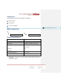
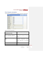
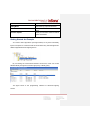
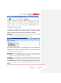
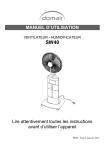
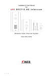
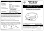
Wireless Relay User Manual
Product Introduction
This Wireless Relay is a standard Zigbee PRO device, model IN-C01-WR-4. It
provides four output Relays and seamlessly docks various Control4 Home
Controllers. Users can remotely control relays to control devices with relay
interface. It supports OTA (Over The Air) to update firmware online through
Zigbee.
Product Features
Seamlessly dock Control4 Home Controllers, such as HC200, HC300,
HC250, HC800,etc
Use the latest EM357 chip and EmberZNet5.1.2 protocol stack, perfectly
docks to Control4 system
Work as a router so that other Zigbee devices can join Zigbee mesh via the
wireless Relay
Provide four relays output contacts for relay-interface devices such as
garage doors, electric curtains, projection screen, fireplaces, etc
Offer Both Standard Relay Output and PANEL_NONDIM_LIGHT Output
Connections (4 channels respectively), configurable to the actual needs
OTA support to update firmware through Zigbee online
Preloaded low radio power firmware; high radio power firmware available
through OTA update to enhance link quality
Packing List
The Following components are included in the package:
Wireless Relay
User Manual
12 V AC-DC Adapter
批注 [S1]: 该图形需要替换成真实的产品照片
Module Appearance
状态指示灯 LED indications
安装定位孔 Hole positions
Product Specifications
Power Supply
AC 100V ~ 240V, 50Hz/60Hz
Output Power
0.5A @ 50V or less
Dimensions
70mm(D) x 55mm(W) x 20mm (H)
Communications
Zigbee, IEEE802.15.4, 2.4G
15 Channels
No Barrier:
15 m
With Barrier:
5m
Operating Temperature
-20℃ ~ 70℃
Operating Humidity
5% ~ 95%
CAUTION!: for safe use of this product, please strictly follow the
specifications above.
Installation Instructions
1. Installation position of Equipment must meet the following requirements
Within the range of Zigbee communicating network
Keep way from other 2.4 GHz devices such as Wi-Fi, Bluetooth
Keep away from metal objects
IMPORTANT!:Strictly follow the requirements above so that the
product can work efficiently.
2. Hardware Installation Instruction
Relay4
Relay3
Relay2
Relay1
11
12
21
22
31
42
41
32
31
22
21
12
11
32
41
42
Relay1 Contact
Relay2 Contact
Relay3 Contact
Relay4 Contact
External 5 ~ 24V
AC-DC Power
16-28AWG From
Equipment
Wireless Relay provides 10 terminals, in which:
V+ & V-
External Power Input(AC-DC Adapter)
+5V ~ +24V, Standard Voltage 12 V
Pin 11 & 12
Relay 1 Contact
Pin 21 & 22
Relay 2 Contact
Pin 31 & 32
Pin 41 & 42
Relay 3 Contact
Relay 4 Contact
Connect positive and negative terminals of AC-DC Adapter (cable with
white line is positive) to the positive and negative terminals of wireless relay
respectively to start the module.
Wireless Relay provides 4 relay contacts outputs that can interfaces with
and controls external week current relay interface devices such as curtains
and screens, etc.
Installation Instruction:
1) Open the device shell;
2) Connect the cable and wires following instructions above;
3) Fix it to the wall using screws through the 4 gauge holes;
4) Close the device shell.
Setup and Configurations
Add device
Visit www.insona.cc to download Wireless Relay Driver. Open “Composer”,
Click “Driver->AddDriver”, select and load “inSona_WirelessRelay_4.c4i”.
Then add the relay device to project as shown in the figure below.
Driver Properties Introduction
The Properties of the Wireless Relay in Composer are shown in figure below:
Meaning of these properties are:
Relay 1 Status/Relay 2 Status/Relay Real time display of Relay status
3 Status/Relay 4 Status
Relay 1 Default/Relay 2 Default/ Configure the default relay status
Relay 3 Default/Relay 4 Default
when power-on (relays are normally
open )
Relay 1 and 2 SPDT/ Relay 3 and 4 Configure Relay 1 & 2, Relay 3 & 4 as
SPDT
single-pole
double-throw
switch
(SPDT). Note that it is an analog
SPDT
Hardware Version
Hardware Version
Firmware Version
Firmware Version
Driver Version
Driver Version
Debug Mode
Control the log output of the driver
Refresh Time
Last update time of the information
above
Firmware Update
Display the firmware version and OTA
update information
Getting Started: An Example
You need to add a light driver (see figure below) or any driver with Relay
Input in Composer to control the state of the wireless relay. Also the light driver
added supports Advanced Lighting Scene.
By connecting the Connections between two drivers, users can control
Wireless Relay through the Control4 Light proxy or Relay proxy.
The figure below is the programming interface of advanced lighting
scenes.
OTA Update Instructions
Wireless Relay supports OTA (Over The Air), that means you can update
firmware through Zigbee. The “Firmware Update” in Properties Tab will
indicate the latest firmware version when new updates are available.
If you want to update the firmware, switch to Action tab
Click Update Firmware button to start updating. The “Firmware Update” in
Properties Tab will display the update progress. The new firmware will be
downloaded in proximately 10 minutes.
File verification will be performed after downloading.
IMPORTANT!: The device will restart automatically and load the new
firmware after verfication. Do not cut off the power during the process as it may
lead to non-repairable damage. Usually the loading process will finish in 1
minutes.
After the loading process, Firmware Update will display “Firmware is
updated”, showing the operating firmware has been updated to the version of
the driver.
If the update fails or you need to redo update or downgrade, use the Force
Update Firmware button in Action Tab. The process is the same to Firmware
Update.
Operation and Display
Press the button 4 times for identifying, the Green LED starts to blink.
When the device successfully joined the network, Green LED will be turned off.
Press the button 9 times to leave Zigbee mesh. When the device goes
offline, the Red LED turns on.
This table describes the Button functions and LED status
Button Tap
Function
Button
Sequence
Red LED and
Green LED binks
once successively,
and red LED turns
on
Power On
Identify
LED status
4
Green LED starts
blinking then goes
off.
Remarks
When the relay has
joined the network
and powered on
again, the green
LED will turn on a
while and turn off,
indicating
rejoin
process
If
Green
LED
doesn’t blink, you
shall press the
button
4
times
again
Leave Zigbee
Mesh
9
Red LED turns on
1. If Red LED
remains off, then
the operation has
failed. Please press
the button 9 times
again.
2. Uers can’t control
the device until
rejoining the Zigbee
Mesh
Troubleshooting
If the Wireless Relay is not working,
1. Check the Power Supply of the wireless relay.
2. Check the Zigbee network status of the wireless relay through Composer.
3. Make sure the Connections between drivers are connected according to
the instructions.
4. Make sure the controlled device works normally.
If you find the green LED is always on after the device is powered on, please
press the button 9 times to leave the former Zigbee mesh. Then press 4 times
to join the network.
For
helps
and
other
questions
on
this
product,
please
visit
http://www.insona.cc.
Regulatory Compliance
inSona Wireless relay complies with standards established by the
following regulatory bodies: Federal Communications Commission (FCC) and
Conformite Europeene (CE).
FCC
FCC ID: 2ACRFC01WR4
This device complies with Part 15 of the FCC Rules. Operation subject to the
following two conditions:
(1) This device may not cause harmful interference, and
(2) This device must accept any interference received, including interference
that may cause undesired operation.
Note: This equipment has been tested and found to comply with the limits for a
Class B digital device, pursuant to part 15 of the FCC Rules. These limits are
designed to provide reasonable protection against harmful interference in a
residential installation. This equipment generates, uses and can radiate radio
frequency energy and, if not installed and used in accordance with the
instructions, may cause harmful interference to radio communications.
However, there is no guarantee that interference will not occur in a particular
installation. If this equipment does cause harmful interference to radio or
television reception, which can be determined by turning the equipment off and
on, the user is
encouraged to try to correct the interference by one or more of the following
measures:
—Reorient or relocate the receiving antenna.
—Increase the separation between the equipment and receiver.
—Connect the equipment into an outlet on a circuit different from that to
which the receiver is connected.
—Consult the dealer or an experienced radio/TV technician for help.
CE
inSona declare that the product : Wireless Relay, Model Number IN-C01-WO,
to which this declaration relates, is in conformity with the following standards :
EN 55022
EN 55024
EN 300328 (RF)
EN 301489 (RF)