1
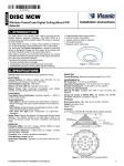
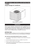
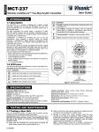
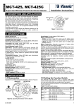
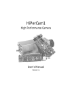
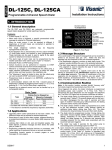
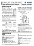
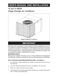
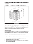
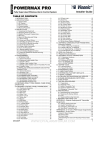
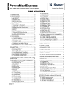
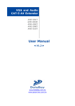
MCR-308, MCR-308T, MCR-308T RL Installation Instructions Wireless Interface for Hard-Wire Control Panels 1. INTRODUCTION 1.1 Purpose and Use The MCR-308 is a wireless PowerCode receiver designed to convert a regular hard-wired control panel into a hybrid wireless system, as demonstrated in Figure 1. MCR-308T (868.95MHz) is an MCR-308 that includes an "underboard" tamper switch that opens if the unit is forcibly removed from the mounting place. In this case, a tamper message is transmitted. MCR-308T RL is an MCR-308T with an 8-relay interface (RL-8) for dry contact outputs. MCR-308T & MCR-308T RL include 2 diversity antennas - allowing high performance reception, overcoming "in-band" interference. The unit provides 8 open collector outputs - 4 zone outputs and 4 status outputs (see Para. 1.3 for details). With the MCR-308 serving as an interface between wireless transmitters and the control panel, the control panel’s zone inputs “see” regular wired loops, as if they were directly connected to hard-wired devices. The states of the receiver outputs (open circuit or closed circuit) determine whether the control panel’s zone inputs are in alarm or not. For MCR-308 T only, when the alarm system is disarmed the zone output of the transmitted message is activated if a supervised transmitter fails to send its attendance message within 8 min. In addition, the zone output of the transmitter / detector with low battery condition, will be activated within the first two minutes after the armed system is disarmed. B. Status Outputs In addition to the 4 zone outputs, the MCR-308 provides 4 opencollector status outputs that function as follows: Tamper: This output is activated once a TAMPER state is detected in a transmitter, in an expander unit or in the MCR-308 receiver itself. In addition, (MCR-308 T only), when the alarm system is armed this output is activated once a supervised transmitter fails to send its attendance message within 4-8 hours. Inactivity: This output is activated if a supervised transmitter fails to send its attendance message within 4-8 hours, and also upon sensing expander inactivity for 10 seconds. Low Battery: This output is activated whenever a low battery message is received from one of the transmitters/detectors. The output is reset by replacing the battery in the transmitter that sent the low battery message and transmitting once again. Jamming: This output is activated if an interference (channel jamming) is detected on the RF channel for more than 30 seconds. It is reset a few seconds after the jamming stops. C. Optional Dry-Contact Interface Figure 1. Typical Application of the MCR-308 A notable feature of the MCR-308 is its compatibility with both regular PowerCode and Code-Secure™ transmitters. Code secure™ transmitters are mainly used to arm/disarm an alarm system or in other control applications, to prevent “code grabbing” by people with malicious intents. Three operating modes are available: Normal - the receiver stands by for regular reception Learn - Enrolling transmitter and expander IDs to the MCR-308 memory (see Para. 1.4). Test - allows the installer to test the system. 1.2 Expansion Option Although the MCR-308 provides only 4 zone outputs, its span of control can be increased by adding up to three MCX-8 expander modules, connected via a 4-wire expansion bus (see Figure 2). Full data on the MCX-8 is given in Publication DE4050-. An 8-relay interface unit - the RL-8 - complements the MCR-308 where dry-contact outputs are required. For such applications we recommend the MCR-308/RL, a combined product in which one MCR-308 and one RL-8 are interconnected in the factory and mounted within a common housing. The RL-8 can also be used in conjunction with the MCX-8 expander to convert the expander’s open-collector outputs into dry-contact outputs. For such applications we recommend the MCX-8/RL, a combined product in which one MCX-8 and one RL-8 are interconnected in the factory and mounted within a common housing. Full data on the RL-8 interface unit is given in Publication DE5712-. 1.4 Enrolling Capability For proper operation, the MCR-308 must recognize the ID code of each wireless transmitter used in the system and of each MCX-8 expander added to the system. Each transmitter must be enrolled to the actual zone output it is meant to trigger (up to 4 transmitters per zone output), and each expander (if used) must be also be enrolled to the MCR-308. Transmitter and expander enrolling procedures are given in Paragraphs 3.5 and 3.6. 1.5 Construction Details (Figure 3) The MCR-308 is packaged in a two-part plastic cabinet, with vacant space for an MCX-8 expander module (that adds 8 outputs to the receiver) or the RL-8 dry contact interface unit (that converts the open collector outputs into dry contact outputs). WIRING KNOCKOUT (1 OF 4) RF RECEIVER ANTENNA ANTENNA TERMINAL “CLEAR” JUMPER CLEAR LEARN OUT1_TOG N.O. OPTIONAL BUS CONN. (OPTION) Figure 2. Expanded System Configuration Each expander provides 8 additional outputs, and together with the 4 zone outputs of the MCR-308 the total number of zone outputs will amount to 28. Twenty eight zone outputs multiplied by four wireless devices per output produce a total of 112 differently coded wireless devices that can be used in a single system. 1.3 Available Outputs A. Zone Outputs The MCR-308 features 4 open-collector zone outputs (expandable to 28 outputs - see Figure 2). Up to 4 transmitters/ detectors can be enrolled to each zone output (see Para. 1.4). DE3191 PROGRAMMING SWITCHES YELLOW LED RED LED MOUNTING HOLE (1 OF 2) EXP. MCR–308 1 EXPANSION BUS TERMINALS 2 3 OUTPUTS BUZZER 4 TAMPER SWITCH WIRING HOLES OUTPUT TERMINAL BLOCK Figure 3A. MCR-308 with Cover Removed 1 WIRING KNOCKOUT DIVERSITY ANTENNAS RF RECEIVER (1 OF 4) CLEAR OPTIONAL BUS CONN. (OPTION) “CLEAR” JUMPER PROGRAMMING SWITCHES LEARN OUT1_TOG N.O. YELLOW LED MOUNTING HOLE (1 OF 2) RED LED EXPANSION BUS TERMINALS MODULE EDGE SUPPORT BUZZER 1 2 3 OUTPUTS 4 TAMPER SWITCH WIRING HOLES OUTPUT TERMINAL BLOCK Figure 3B. MCR-308T with Cover Removed WIRING KNOCKOUT (1 OF 4) DIVERSITY ANTENNAS RF RECEIVER RL- 8 CLEAR “CLEAR” JUMPER PROGRAMMING SWITCHES LEARN OUT1_TOG N.O. Some variants use a semi-rigid vertical antenna that extends out of the housing. Other variants use an internal wire antenna. 1.6 LED Tasks in Normal Operation The MCR-308 has two LED indicators: • SIGNAL indicator (red) • TROUBLE indicator (yellow) SIGNAL indicator: This LED lights steadily for 2 seconds upon reception of a valid message. If noise or unrecognizable RF signal are received, the LED flickers. TROUBLE indicator: This LED is extinguished while all is well, but lights steadily for as long as the TAMPER, LOW BATTERY and INACTIVITY outputs are activated. The trouble indicator will remain lighted until all trouble is cleared (restore/attendance messages arrive from all trouble sources). To find out which zone is “in trouble”, see Para. 4.6. Note: Both indicators have other functions during a learning session (see Paragraphs 3.5 and 3.6). YELLOW LED MOUNTING HOLE (1 OF 2) RED LED BUZZER 1 2 3 OUTPUTS 4 TAMPER SWITCH WIRING HOLES OUTPUT TERMINAL BLOCK Figure 3C. MCR-308TRL with Cover Removed 2. SPECIFICATIONS RF SECTION Front-End Module: Superheterodyne UHF receiver. Operating Frequency (MHz): 315, 433.92, 868.95 or other UHF channel per local requirements in country of use. DATA PROCESSING SECTION ID codes: Over 16,000,000 possible 24-bit combinations. Total Message Length: 36 bits (66 bits for code secure devices) ID Learning Capacity: 112 different ID codes Expander Bus: 4-wires (12V+, [–], DATA and COMMON) ELECTRICAL DATA Zone Outputs: 4, up to 100 mA each, open-collector type Status outputs: 4, up to 100 mA each, open-collector type Output No. 1 modes: Pulsed (2 seconds) or toggle, selected with DIP switch Output Polarities: N.O. or N.C., selected with DIP switch Tamper Switch Ratings: 0.1 A / 30 VDC. Input Voltage Range: 10.5 - 16 VDC Max. Current Drain (@ 12 VDC): 25 mA (STBY) PHYSICAL Operating Temperatures: 0°C to 49°C (32°¡F to 120°¡F). Dimensions (H x W x D): 108 x 165 x 38 mm (4-1/4 x 6-1/2 x 1-1/2"). Weight (including rigid antenna): 214 g (7.5 oz). Compliance with Standards: Meets FCC part 15, ETS 300-220, ETS 300-683, MPT 1340 requirements and EN50131-5-3. EN 50131-1 Grade 1 Class II for MCR-308, EN 50131-1 Grade 2 Class II for MCR-308T and MCR-308T RL. AUXILIARY EQUIPMENT MCX-8: Eight-output zone expander; RL-8: Eight-relay interface unit. 3. PROGRAMMING 3.1 Helpful Hints A learning session is required to let the MCR-308 learn the ID codes of individual wireless transmitters and link each transmitter to a specific output (up to 4 transmitters per output). In addition, it is necessary to register in the receiver’s memory the ID code of any MCX-8 expander used in the system. If these codes are not “learned”, the expanders will not function. The quickest way to conduct a learning session is on a work bench, with every transmitter you need within reach, and where you may observe the receiver’s indicator LEDs and listen to the buzzer. 3.2 Initial Steps A. Remove the screw that secures the cover to the base and remove the cover as shown in Figure 4. B. The semi-rigid antenna supplied with the MCR-308 is taped to the inner part of the cover. Detach the antenna from its storage position, insert its straight tip into the antenna terminal and tighten the screw well. See Figure 3 for antenna terminal location. C. Gather up all transmitters used in the system and mark each one according to the desired deployment plan. D. Temporarily power up the MCR-308 by connecting a 12 V battery or a 12 VDC power supply across its 12 V input terminals. Observe polarity! 3.3 Selecting the Zone Output In order to enroll a transmitter to a specific zone output, you must first select the desired output number by setting DIP switches SW1 through SW-5 as shown in Table 1. A (–) sign indicates an off position of the switch. Table 1. Output Selection Chart Zone Output # 1 2 DIP Switches 3 4 1 2 3 4 ON – ON – – ON ON – – – – ON – – – – – – – – 5 6 7 ON – ON – ON ON ON ON ON – – – – – – 8 – – – ON – Output No. 4 9 ON – – ON – Output No. 5 5 Wired Output Selected MCR-308 Output No. 1 Output No. 2 Output No. 3 Output No. 4 1 Figure 4. Removing the Top Cover 2 ST EXPANDER Output No. 1 Output No. 2 Output No. 3 DE3191 Zone Output # 10 1 2 DIP Switches 3 4 Wired Output Selected – ON – ON – Output No. 6 11 ON ON – ON – Output No. 7 12 – – ON ON – 5 Output No. 8 ND 13 14 15 16 17 18 19 20 ON – ON – ON – ON – – ON ON – – ON ON – ON ON ON – – – – ON ON ON ON – – – – – – – – ON ON ON ON ON 2 EXPANDER Output No. 1 Output No. 2 Output No. 3 Output No. 4 Output No. 5 Output No. 6 Output No. 7 Output No. 8 ON ON ON ON ON ON ON ON 3 EXPANDER Output No. 1 Output No. 2 Output No. 3 Output No. 4 Output No. 5 Output No. 6 Output No. 7 Output No. 8 RD 21 22 23 24 25 26 27 28 ON – ON – ON – ON – – ON ON – – ON ON – ON ON ON – – – – ON – – – ON ON ON ON ON 3.4 Selecting Sub-Zone Locations Each zone output is divided into 4 sub-zones, and each sub zone accepts one transmitter ID. Sub zone locations may be selected in ascending order from 1 to 4, by clicking the MCR-308’s tamper switch (a short beep will sound upon each click). The yellow LED will indicate the ordinal number of the selected sub-zone location by a flashing sequence as demonstrated in the following chart: No. of SubClicks Zone Flashing Sequence of the Yellow LED st — — One 1 ....... nd — — Two 2 ...... rd Three 3 — th Four 4 = Flash; — = Pause — — ...... — ...... 3.5 Enrolling Transmitter IDs A single transmission is required to register a transmitter ID in the MCR-308 memory. A. Preparations (1) Prepare all the transmitters and mark each one with the desired target zone output and sub zone location. Note: In case of PIR detectors in which batteries are already installed, cover the detector’s lens to prevent accidental transmission during the learning session. (2) Remove the MCR-308 cover. The buzzer will beep once upon release of the tamper switch. B. Transmitter Enrolling Procedure (1) Set DIP switch SW-8 to ON (LEARN mode). The yellow LED will flash at a constant rate throughout the learn period. (2) Use DIP switches 1 through 5 to select the desired zone output (see Table 1). (3) Click the MCR-308 tamper switch 1 or 2 or 3 or 4 times to select the desired sub-zone (see Para. 3.4). Each click advances to the next sub-zone. The status of the selected sub-zone location will be shown by the red LED: Status Red LED Response Location is free LED Flashes Location already contains an ID LED Lights steadily To clear a “busy” location, refer to Para. 3.7. (4) If the sub-zone location is free, initiate a transmission from the transmitter you wish to enroll in the selected sub zone. The red LED and the buzzer can respond as follows: Red LED & Buzzer Response Significance Red LED: lights steadily; Transmitter ID enrolled Buzzer: “victory melody” ( Red LED: lights steadily; ) Buzzer: “victory melody” ( twice Red LED: continues to flash; Buzzer: remains silent ) DE3191 Transmitter ID enrolled again (the same ID is already saved in another location) Note: You can not enroll a transmitter in a busy location. However, if you try to enroll a transmitter into a busy location, and the same ID is already enrolled in another location, the buzzer will sound a long beep. (5) Repeat Steps 2 through 4 above for all the remaining transmitters. (6) When done, quit the LEARN mode by setting SW-8 to OFF. Notes: 1. If the transmitter used is a wireless detector, remove its battery to prevent accidental transmissions at a later stage of the learning session. 2. If you leave SW-8 in the ON position and no further learning activity takes place for 5 minutes, the LEARN mode will be automatically abandoned. C. Memory Content Verification To check whether a specific transmitter’s ID is programmed in a certain zone, select the zone output and then the sub-zone in question and initiate a transmission. If the saved and transmitted IDs match, the buzzer will sound the victory melody ( ). If there is no match but the same ID is already enrolled in another sub-zone location, the buzzer will sound a long beep. If the ID is not recognized by the MCR-308, the buzzer will remain silent. 3.6 Enrolling Expander IDs It is necessary to “teach” the MCR-308 which expander is related to which group of zone outputs. The expander’s specific ID must therefore be programmed into a special expander location in the MCR-308 memory. A. Preparations (1) Connect the expander (or expanders) to the expansion bus. (2) Remove the MCR-308 cover. The buzzer will beep once upon release of the tamper switch. B. Expander Enrolling Procedure (1) Set DIP switch SW-8 to ON (LEARN mode). The yellow LED will flash at a constant rate throughout the learn period. (2) Use DIP switches 1 through 5 to select the desired expander memory location as shown in Table 2 below: Table 2. Expander Location Selection Chart Expander DIP Switches Related Zone Module 1 2 3 4 5 Outputs st 1 ON — ON ON ON Zones 5 - 12 nd — ON ON ON ON Zones 13 - 20 2 rd 3 ON ON ON ON ON Zones 21 - 28 (3) Click the MCR-308 tamper switch once. The status of the selected expander memory location will be shown by the red LED: Status Red LED Response Location is free Location already contains an ID LED Flashes LED Lights steadily To clear a “busy” location, refer to Para. 3.7 below. (4) Click the expander’s tamper switch once. The red LED and the buzzer will respond as follows: Red LED & Buzzer Response Red LED: lights steadily; ) Buzzer: “victory melody” ( Red LED: flashes at a constant rate Buzzer: remains silent Significance Expander ID enrolled Expander ID not enrolled Note: If not enrolled, check the connections to the bus. (5) Repeat steps 2 and 3 above for all other expanders. When done, quit the LEARN mode by setting SW-8 to OFF. C. Expander ID Verification To check whether a specific expander’s ID is properly programmed, use DIP switches 1 through 5 to select the expander location in question (see Table 2 above). Click the expander’s tamper switch once to send its ID to the MCR-308. If the programmed and transmitted IDs match, the buzzer will sound the victory melody ( ). 3.7 Clearing Specific Transmitter or Expander IDs A. Set DIP switch SW-8 to ON (LEARN mode). The yellow LED will flash at a constant rate throughout the learn period. B. Use DIP switches 1- 5 to select the desired zone output (see Table 1) or the expander module location (see Table 2). Transmitter ID not enrolled 3 Note: If you are clearing a transmitter ID, click the MCR-308 tamper switch 1 or 2 or 3 or 4 times to select the desired sub zone location (see Para. 3.4). If you are about to clear an expander’s ID, click the MCR-308 tamper switch only once. The status of the selected sub-zone location will be shown by the red LED: Status Red LED Response Sub-zone or expander location is free LED Flashes Sub-zone or expander location already contains an ID LED lights steadily C. Mount a jumper across the two CLEAR pins on the MCR-308 circuit board and remove it immediately. The response will be as follows: Response Significance Red LED: flashes at a constant rate Buzzer: “victory melody” ( ) Red LED: continues to light steadily Buzzer: silent Success (ID deleted) Failure D. When done, quit the LEARN mode by setting SW-8 to OFF. 3.8 Global Clearing of the ID Memory Global clearing provides you with a quick fresh start if your MCR-308 has been used in another system, or has been “played with” as part of an experiment A. Remove the cover from the MCR-308. Disconnect the power, wait a few seconds and reconnect the power. This will cause the buzzer to beep 10 times - 1 beep per second. B. Within the limit of the 10 seconds and while the buzzer is still beeping, mount a jumper across the two CLEAR pins, remove it immediately and then mount and remove quickly again. When done, the buzzer will start a series of rapid beeps, at the end of which the “victory melody” ( ) will sound. All transmitter and expander IDs will thus be cleared from the memory. 3.9 What if the ID is Not Enrolled? If the transmitted ID has not been accepted (the buzzer remains silent) although the memory location is free, try transmitting again. If the second attempt is unsuccessful, the transmitter in question may be faulty. Try enrolling another transmitter. 4. INSTALLATION 4.1 Selecting the Location A. The location selected for the MCR-308 must constitute a compromise between maximum reception ability and minimum distance from the control panel. B. The expanders may be located within the control panel’s cabinet (if there is enough room) or near it. C. It is very important to maintain the antenna vertical - the receiver should be installed with the antenna on top, as shown in Figure 3. D. Avoid installing the MCR-308 on or near large metallic objects such as closets, circuit breaker cabinets, air conditioner ducts and fine-mesh window screens. E. Do not locate the unit in close proximity to dense electrical wiring. 4.2 Mounting the Cabinet in Place To install the cabinet, proceed as follows: A. Hold the base against the mounting surface and mark the points for drilling (see mounting holes in Figure 3). B. Drill the mounting holes and insert wall anchors if necessary. Enter the wires into the base through the wiring holes or wiring knockouts. Attach the base to the mounting surface with two long screws. Attention! MCR-308T includes an additional tamper switch (under the board) that is actuated by a leaf spring. A screw that fastens the tamper switch actuator to the mounting surface must be used, as MCR-308T shown. If the actuator is Back tamper switch fixing screw secured and the unit is forcibly removed from its mounting place, the actuator breaks away from the base, causing the tamper switch opening - a tamper alarm is consequently transmitted. C. Complete the wiring as described in Para. 4.3. 4.3 Wiring (Figures 5 and 6) Note: The wiring length should be less than 30m (98 ft.) A. Connect the 4 zone outputs (1, 2, 3, and 4) of the MCR-308 to the desired zone inputs of the control panel in use. B. Connect the four status outputs of the MCR-308 (TAMP, INACT, L. BAT and JAM) to the desired zone inputs of the control panel in use. Note: If the control panel zone inputs are defined as E.O.L., you must use appropriate E.O.L. resistors (see Figure 6). C. Connect the control panel’s 12 VDC (+) and (–) terminals to their counterparts on the left edge of the MCR-308 module. D. If an expander is mounted within the MCR-308 case, connect it to the MCR-308 using the flat cable (supplied with the expander) between the flat cable receptacles on both units. If an expander is mounted away from the MCR-308 in a separate enclosure, use the four bus terminals on both units, connecting each terminal to its counterpart in the other unit E. Make sure the antenna is firmly held in place near the top edge of the PCB. CONTROL PANEL MCR-308U RECEIVER E.O.L. ZONE INPUT E.O.L. RESISTOR OUTPUT DEFINED AS N.C. MCR-308U RECEIVER CONTROL PANEL E.O.L. ZONE INPUT E.O.L. RESISTOR OUTPUT DEFINED AS N.O. Figure 6. Wiring E.O.L. Zones 4.4 Customizing Your Receiver After wiring, it is necessary to set DIP switches 6, 7 and 8 as required for the specific application (see Figure 7). A. Make sure that SW-8 is OFF - the regular operation mode is selected. B. Switch SW-6 determines the zone output polarity (N.O. or N.C.): SW-6 Setting Result ON The MCR-308 zone outputs are N.O. OFF The MCR-308 zone outputs are N.C. Set the switch as required for your particular application. C. Switch SW-7 determines the operating mode of zone output No. 1 (Momentary or Toggle): SW-7 Setting Result ON Zone output 1 operates in the toggle mode OFF Zone 1 operates in the momentary mode Note: Zone No. 1 can be used for Arming/Disarming purposes or for other remote control tasks such as switching lights ON and OFF. Figure 7 can serve as a quick reference to DIP switch tasks. Figure 7. DIP Switch Tasks and Positions Figure 5. Wiring Diagram 4 DE3191 4.5 Testing the Wireless System Testing the system is the best way to find out: - Which transmission is received properly (good reception) - Which transmission is received marginally (poor reception) - Which transmitter has a low battery status The system should be tested at least once in 6 months, to assure proper operation of the wireless communication links. A. Remove the MCR-308 cover. The test mode is selected automatically when the tamper contacts open. The buzzer will sound a single beep upon release of the tamper switch. B. Initiate a transmission from all transmitters, one by one, but allow at least 5 seconds between transmissions. The buzzer will react as follows: Reception Grade Buzzer Reaction Good Victory melody ( ) Poor 1-second beep ( ) Low Battery in Transmitter* 4-second beep ( ) * Regardless of good or poor reception. C. When done, remount the MCR-308 top cover. This will cause the receiver to quit the test mode. 4.6 Finding which Zone is “in Trouble” MCR-308 When PowerCode transmitters send tamper and low battery messages to the MCR-308, or a certain transmitter is found inactive, the MCR-308 responds as follows: • The YELLOW (trouble) LED of the MCR-308 illuminates. • The relevant trouble output of MCR-308 is activated, identifying the type of trouble. To find out which zone (or zones) are “in trouble”, follow these three simple steps: A. Verify that the alarm system is disarmed. B. Use a jumper wire to short the ARM terminal to ground (to the 12 V [–] terminal). C. Check the zone outputs of the MCR-308 (and of the expanders, if used). The output of any zone in which trouble exists will be activated. EXP. MCR–308 1 2 3 OUTPUTS 4 JUMPER WIRE Figure 8. Trouble Locating Jumper Important! Unlike tamper and low battery, the inactivity events are memorized and can therefore be linked to a zone even after the detector renews its activity. Inactivity events are cleared 10 seconds after disconnection of the jumper wire. Note: If a specific zone output is in the activated state at the time of the test (a window or a door has been left open), but there is no trouble in this zone - the zone output will be deactivated for as long as the ARM terminal is grounded. Upon disconnecting the ARM terminal from the 12 V (–) terminal, all zone outputs will revert to their previous states. 5. MISCELLANEOUS COMMENTS 5.1 The Effect of Transmitter Type on Alarm Output Behavior The PowerCode system allows the MCR-308 to make a distinction between devices that report alarm only (such as PIR detectors and pendant transmitters) and detectors such as magnetic switches that report both alarm and restore. The MCR-308 responds to an alarm transmitted by devices that report alarm only by changing the state of the associated output for 2 seconds and then restoring it to the previous state. An alarm message transmitted by restoral-reporting device “tells” the receiver to expect a restoral message after an alarm. The MCR-308 will change the state of the associated output upon alarm from one sub-zone or more, and will maintain the output in alarm. The output will revert to its original state only upon reception of a restoral message from the alarming sub-zone (or from all alarming sub-zones in case of multiple alarms). 5.2 The Effect of Transmitter Type on the Inactivity (INACT) Output Supervised transmitters transmit an “attendance message” at regular intervals. If a supervised transmitter fails to send this message on time, the MCR-308 will trigger the INACT output. On the other hand, failure to receive an attendance message from a transmitter identified as a non-supervised device will be ignored by the MCR-308. 5.3 Product Limitations Visonic Ltd. wireless systems are very reliable and are tested to high standards. However, due to their low transmitting power and limited range (required by FCC and other regulatory authorities), there are some limitations to be considered: A. Receivers may be blocked by radio signals occurring on or near their operating frequencies. B. A receiver can only receive one transmitted signal at a time. C. Wireless equipment should be tested regularly to determine whether there are sources of interference and to protect against faults. The user is cautioned that changes or modifications to the unit, not expressly approved by Visonic Ltd., could void the user's FCC authority to operate the equipment. The PowerCode system allows the MCR-308 to make a distinction between supervised and non-supervised transmitters. The 315 MHz version of this device complies with Part 15 of the FCC Rules. Operation is subject to the following two conditions: (1) This device may not cause harmful interference, and (2) This device must accept any interference received, including interference that may cause undesired operation. The digital circuit of this device has been tested and found to comply with the limits for a Class B digital device, pursuant to Part 15 of the FCC Rules. These limits are designed to provide reasonable protection against harmful interference in residential installations. This equipment generates, uses and can radiate radio frequency energy and, if not installed and used in accordance with the instructions, may cause harmful interference to radio and television reception. However, there is no guarantee that interference will not occur in a particular installation. If this device does cause such interference, which can be verified by turning the device off and on, the user is encouraged to eliminate the interference by one or more of the following measures: – Re-orient or re-locate the receiving antenna. – Increase the distance between the device and the receiver. – Connect the device to an outlet on a circuit different from the one which supplies power to the receiver. – Consult the dealer or an experienced radio/TV technician. DE3191 5 WARRANTY Visonic Limited (the “Manufacturer") warrants this product only (the "Product") to the original purchaser only (the “Purchaser”) against defective workmanship and materials under normal use of the Product for a period of twelve (12) months from the date of shipment by the Manufacturer. This Warranty is absolutely conditional upon the Product having been properly installed, maintained and operated under conditions of normal use in accordance with the Manufacturers recommended installation and operation instructions. Products which have become defective for any other reason, according to the Manufacturers discretion, such as improper installation, failure to follow recommended installation and operational instructions, neglect, willful damage, misuse or vandalism, accidental damage, alteration or tampering, or repair by anyone other than the manufacturer, are not covered by this Warranty. The Manufacturer does not represent that this Product may not be compromised and/or circumvented or that the Product will prevent any death and/or personal injury and/or damage to property resulting from burglary, robbery, fire or otherwise, or that the Product will in all cases provide adequate warning or protection. The Product, properly installed and maintained, only reduces the risk of such events without warning and it is not a guarantee or insurance that such events will not occur. THIS WARRANTY IS EXCLUSIVE AND EXPRESSLY IN LIEU OF ALL OTHER WARRANTIES, OBLIGATIONS OR LIABILITIES, WHETHER WRITTEN, ORAL, EXPRESS OR IMPLIED, INCLUDING ANY WARRANTY OF MERCHANTABILITY OR FITNESS FOR A PARTICULAR PURPOSE, OR OTHERWISE. IN NO CASE SHALL THE MANUFACTURER BE LIABLE TO ANYONE FOR ANY CONSEQUENTIAL OR INCIDENTAL DAMAGES FOR BREACH OF THIS WARRANTY OR ANY OTHER WARRANTIES WHATSOEVER, AS AFORESAID. THE MANUFACTURER SHALL IN NO EVENT BE LIABLE FOR ANY SPECIAL, INDIRECT, INCIDENTAL, CONSEQUENTIAL OR PUNITIVE DAMAGES OR FOR LOSS, DAMAGE, OR EXPENSE, INCLUDING LOSS OF USE, PROFITS, REVENUE, OR GOODWILL, DIRECTLY OR INDIRECTLY ARISING FROM PURCHASER’S USE OR INABILITY TO USE THE PRODUCT, OR FOR LOSS OR DESTRUCTION OF OTHER PROPERTY OR FROM ANY OTHER CAUSE, EVEN IF MANUFACTURER HAS BEEN ADVISED OF THE POSSIBILITY OF SUCH DAMAGE. THE MANUFACTURER SHALL HAVE NO LIABILITY FOR ANY DEATH, PERSONAL AND/OR BODILY INJURY AND/OR DAMAGE TO PROPERTY OR OTHER LOSS WHETHER DIRECT, INDIRECT, INCIDENTAL, CONSEQUENTIAL OR OTHERWISE, BASED ON A CLAIM THAT THE PRODUCT FAILED TO FUNCTION. However, if the Manufacturer is held liable, whether directly or indirectly, for any loss or damage arising under this limited warranty, THE MANUFACTURER'S MAXIMUM LIABILITY (IF ANY) SHALL NOT IN ANY CASE EXCEED THE PURCHASE PRICE OF THE PRODUCT, which shall be fixed as liquidated damages and not as a penalty, and shall be the complete and exclusive remedy against the Manufacturer. When accepting the delivery of the Product, the Purchaser agrees to the said conditions of sale and warranty and he recognizes having been informed of. Some jurisdictions do not allow the exclusion or limitation of incidental or consequential damages, so these limitations may not apply under certain circumstances. The Manufacturer shall be under no liability whatsoever arising out of the corruption and/or malfunctioning of any telecommunication or electronic equipment or any programs. The Manufacturers obligations under this Warranty are limited solely to repair and/or replace at the Manufacturer’s discretion any Product or part thereof that may prove defective. Any repair and/or replacement shall not extend the original Warranty period. The Manufacturer shall not be responsible for dismantling and/or reinstallation costs. To exercise this Warranty the Product must be returned to the Manufacturer freight pre-paid and insured. All freight and insurance costs are the responsibility of the Purchaser and are not included in this Warranty. This warranty shall not be modified, varied or extended, and the Manufacturer does not authorize any person to act on its behalf in the modification, variation or extension of this warranty. This warranty shall apply to the Product only. All products, accessories or attachments of others used in conjunction with the Product, including batteries, shall be covered solely by their own warranty, if any. The Manufacturer shall not be liable for any damage or loss whatsoever, whether directly, indirectly, incidentally, consequentially or otherwise, caused by the malfunction of the Product due to products, accessories, or attachments of others, including batteries, used in conjunction with the Products. This Warranty is exclusive to the original Purchaser and is not assignable. This Warranty is in addition to and does not affect your legal rights. Any provision in this warranty which is contrary to the Law in the state or country were the Product is supplied shall not apply. Warning:The user must follow the Manufacturer’s installation and operational instructions including testing the Product and its whole system at least once a week and to take all necessary precautions for his/her safety and the protection of his/her property. 1/08 Transmitter Deployment Table Zone Output SubZone 1 2 3 Transmitter Type Zone Output SubZone 1 2 3 4 8 1 1 9 Location / Task / Name of Holder 3 4 2 3 4 3 4 10 1 3 4 11 1 1 2 3 4 3 4 12 1 1 2 2 3 4 3 4 13 1 1 2 2 3 4 3 4 7 1 2 2 6 1 2 3 4 5 Location / Task / Name of Holder 2 2 4 Transmitter Type 14 1 1 2 2 3 4 3 4 W.E.E.E. Product Recycling Declaration For information regarding the recycling of this product you must contact the company from which you orignially purchased it. If you are discarding this product and not returning it for repair then you must ensure that it is returned as identified by your supplier. This product is not to be thrown away with everyday waste. Directive 2002/96/EC Waste Electrical and Electronic Equipment. VISONIC LTD. (ISRAEL): P.O.B 22020 TEL-AVIV 61220 ISRAEL. PHONE: (972-3) 645-6789, FAX: (972-3) 645-6788 VISONIC INC. (U.S.A.): 65 WEST DUDLEY TOWN ROAD, BLOOMFIELD CT. 06002-1376. PHONE: (860) 243-0833, (800) 223-0020. FAX: (860) 242-8094 VISONIC LTD. (UK): 7 COPPERHOUSE COURT, CALDECOTTE, MILTON KEYNES. MK7 8NL. PHONE: (0870) 7300800 FAX: (0870) 7300801 INTERNET: www.visonic.com VISONIC LTD 2008 6 MCR-308, MCR-308T, MCR-308T RL DE3191- (REV. 8 08/08) DE3191