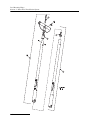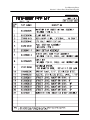
1
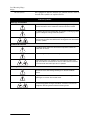
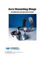
Isco Mounting Rings Installation and Operation Guide Part # 60-3203-061 Copyright © 1997. All rights reserved, Teledyne Isco Revision M, December 2014 Foreword This instruction manual is designed to help you gain a thorough understanding of the operation of the equipment. Teledyne Isco recommends that you read this manual completely before placing the equipment in service. Although Teledyne Isco designs reliability into all equipment, there is always the possibility of a malfunction. This manual may help in diagnosing and repairing the malfunction. If a problem persists, call or e-mail Teledyne Isco technical support for assistance. Simple difficulties can often be diagnosed over the phone. For faster service, please have your serial number ready. If it is necessary to return the equipment to the factory for service, please follow the shipping instructions provided by technical support, including the use of the Return Merchandise Authorization (RMA) specified. Be sure to include a note describing the malfunction. This will aid in the prompt repair and return of the equipment. Teledyne Isco welcomes suggestions that would improve the information presented in this manual or enhance the operation of the equipment itself. Teledyne Isco is continually improving its products and reserves the right to change product specifications, replacement parts, schematics, and instructions without notice. Contact Information Customer Service Phone: (800) 228-4373 (USA, Canada, Mexico) (402) 464-0231 (Outside North America) Fax: (402) 465-3022 Email: [email protected] Technical Support Phone: Toll Free (866) 298-6174 (Samplers, Flow Meters and Multi-parameter Probes) Toll Free (800) 775-2965 (Syringe Pumps and Liquid Chromatography) Email: [email protected] Return equipment to: 4700 Superior Street, Lincoln, NE 68504-1398 Other Correspondence Mail to: P.O. Box 82531, Lincoln, NE 68501-2531 Email: [email protected] Revised April 2014 Isco Mounting Rings Safety Isco Mounting Rings Safety General Warnings Before installing, operating, or maintaining this equipment, it is imperative that all hazards and preventive measures are fully understood. While specific hazards may vary according to location and application, take heed in the following general warnings: WARNING This instrument has not been certified for use in “hazardous locations” as defined by the National Electrical Code. WARNING Avoid hazardous practices! If you use this instrument in any way not specified in this manual, the protection provided by the instrument may be impaired; this will increase your risk of injury. AVERTISSEMENT Éviter les usages périlleux! Si vous utilisez cet instrument d’une manière autre que celles qui sont specifiées dans ce manuel, la protection fournie de l’instrument peut être affaiblie; cela augmentera votre risque de blessure. Hazard Severity Levels This manual applies Hazard Severity Levels to the safety alerts, These three levels are described in the sample alerts below. CAUTION Cautions identify a potential hazard, which if not avoided, may result in minor or moderate injury. This category can also warn you of unsafe practices, or conditions that may cause property damage. WARNING Warnings identify a potentially hazardous condition, which if not avoided, could result in death or serious injury. DANGER DANGER – limited to the most extreme situations to identify an imminent hazard, which if not avoided, will result in death or serious injury. iii Isco Mounting Rings Safety Hazard Symbols The equipment and this manual use symbols used to warn of hazards. The symbols are explained below. Hazard Symbols Warnings and Cautions The exclamation point within the triangle is a warning sign alerting you of important instructions in the instrument’s technical reference manual. The lightning flash and arrowhead within the triangle is a warning sign alerting you of “dangerous voltage” inside the product. Pinch point. These symbols warn you that your fingers or hands will be seriously injured if you place them between the moving parts of the mechanism near these symbols. Symboles de sécurité Ce symbole signale l’existence d’instructions importantes relatives au produit dans ce manuel. Ce symbole signale la présence d’un danger d’électocution. Risque de pincement. Ces symboles vous avertit que les mains ou les doigts seront blessés sérieusement si vous les mettez entre les éléments en mouvement du mécanisme près de ces symboles Warnungen und Vorsichtshinweise Das Ausrufezeichen in Dreieck ist ein Warnzeichen, das Sie darauf aufmerksam macht, daß wichtige Anleitungen zu diesem Handbuch gehören. Der gepfeilte Blitz im Dreieck ist ein Warnzeichen, das Sei vor “gefährlichen Spannungen” im Inneren des Produkts warnt. Vorsicht Quetschgefahr! Dieses Symbol warnt vor einer unmittelbar drohenden Verletzungsgefahr für Finger und Hände, wenn diese zwischen die beweglichen Teile des gekennzeichneten Gerätes geraten. iv Isco Mounting Rings Table of Contents Section 1 Preparation 1.1 Introduction . . . . . . . . . . . . . . . . . . . . . . . . . . . . . . . . . . . . . . . . . . . . . . . . . . . . . . . . 1.2 Sensor Carriers . . . . . . . . . . . . . . . . . . . . . . . . . . . . . . . . . . . . . . . . . . . . . . . . . . . . . 1.3 Submerged Probe . . . . . . . . . . . . . . . . . . . . . . . . . . . . . . . . . . . . . . . . . . . . . . . . . . . 1.4 Standard and Extended Range Area Velocity Sensors . . . . . . . . . . . . . . . . . . . . . . 1.5 Low Profile Area Velocity Sensor . . . . . . . . . . . . . . . . . . . . . . . . . . . . . . . . . . . . . . . 1.6 Bubble Line . . . . . . . . . . . . . . . . . . . . . . . . . . . . . . . . . . . . . . . . . . . . . . . . . . . . . . . . 1.7 Dissolved Oxygen Sensor . . . . . . . . . . . . . . . . . . . . . . . . . . . . . . . . . . . . . . . . . . . . . 1.8 pH Probe . . . . . . . . . . . . . . . . . . . . . . . . . . . . . . . . . . . . . . . . . . . . . . . . . . . . . . . . . . 1.9 Temperature Probe . . . . . . . . . . . . . . . . . . . . . . . . . . . . . . . . . . . . . . . . . . . . . . . . . . 1.10 Sensor Mounting Plate . . . . . . . . . . . . . . . . . . . . . . . . . . . . . . . . . . . . . . . . . . . . . . 1-1 1-1 1-2 1-3 1-3 1-4 1-4 1-5 1-7 1-8 Section 2 Spring Rings 2.1 Preparation . . . . . . . . . . . . . . . . . . . . . . . . . . . . . . . . . . . . . . . . . . . . . . . . . . . . . . . . 2-1 2.2 Installation . . . . . . . . . . . . . . . . . . . . . . . . . . . . . . . . . . . . . . . . . . . . . . . . . . . . . . . . 2-3 Section 3 Scissors Rings 3.1 Large Pipe Applications . . . . . . . . . . . . . . . . . . . . . . . . . . . . . . . . . . . . . . . . . . . . . . 3.1.1 Partial Pipe or Invert Mounting . . . . . . . . . . . . . . . . . . . . . . . . . . . . . . . . . . 3.1.2 Kit Selection . . . . . . . . . . . . . . . . . . . . . . . . . . . . . . . . . . . . . . . . . . . . . . . . . . 3.2 Assembly . . . . . . . . . . . . . . . . . . . . . . . . . . . . . . . . . . . . . . . . . . . . . . . . . . . . . . . . . . 3.3 Installation . . . . . . . . . . . . . . . . . . . . . . . . . . . . . . . . . . . . . . . . . . . . . . . . . . . . . . . . 3-1 3-1 3-2 3-2 3-4 Section 4 ADFM and accQmin Velocity Profiling Sensors 4.1 Circular Channels . . . . . . . . . . . . . . . . . . . . . . . . . . . . . . . . . . . . . . . . . . . . . . . . . . . 4.1.1 Mounting Plates and Rings . . . . . . . . . . . . . . . . . . . . . . . . . . . . . . . . . . . . . . 4.1.2 Flow Conditioning Platform . . . . . . . . . . . . . . . . . . . . . . . . . . . . . . . . . . . . . 4.2 Rectangular Channels. . . . . . . . . . . . . . . . . . . . . . . . . . . . . . . . . . . . . . . . . . . . . . . . 4.3 Trapezoidal Channels . . . . . . . . . . . . . . . . . . . . . . . . . . . . . . . . . . . . . . . . . . . . . . . . 4-1 4-1 4-2 4-2 4-2 Section 5 Street Level Installation System 5.1 Introduction . . . . . . . . . . . . . . . . . . . . . . . . . . . . . . . . . . . . . . . . . . . . . . . . . . . . . . . . 5.2 Assembly . . . . . . . . . . . . . . . . . . . . . . . . . . . . . . . . . . . . . . . . . . . . . . . . . . . . . . . . . . 5.3 Installation . . . . . . . . . . . . . . . . . . . . . . . . . . . . . . . . . . . . . . . . . . . . . . . . . . . . . . . . 5.3.1 Sensor Calibration . . . . . . . . . . . . . . . . . . . . . . . . . . . . . . . . . . . . . . . . . . . . . 5.3.2 Removal . . . . . . . . . . . . . . . . . . . . . . . . . . . . . . . . . . . . . . . . . . . . . . . . . . . . . 5.4 Replacement Parts List. . . . . . . . . . . . . . . . . . . . . . . . . . . . . . . . . . . . . . . . . . . . . . . 5-1 5-3 5-5 5-7 5-7 5-9 List of Figures 1-1 Carrier Base Plate . . . . . . . . . . . . . . . . . . . . . . . . . . . . . . . . . . . . . . . . . . . . . . . . . . 1-1 1-2 Mounting the carrier on a ring or plate . . . . . . . . . . . . . . . . . . . . . . . . . . . . . . . . . 1-1 v Isco Mounting Rings Table of Contents 1-3 Attaching the Submerged Probe Carrier . . . . . . . . . . . . . . . . . . . . . . . . . . . . . . . . 1-4 Standard and Extended Range Area Velocity Sensor . . . . . . . . . . . . . . . . . . . . . . 1-5 Low Profile Area Velocity Sensor Mounting . . . . . . . . . . . . . . . . . . . . . . . . . . . . . . 1-6 Attaching the Low Profile Sensor to the Optional Carrier . . . . . . . . . . . . . . . . . . 1-7 Connecting the Bubble Line . . . . . . . . . . . . . . . . . . . . . . . . . . . . . . . . . . . . . . . . . . 1-8 Attaching the D.O. Sensor . . . . . . . . . . . . . . . . . . . . . . . . . . . . . . . . . . . . . . . . . . . . 1-9 pH Probe Carrier . . . . . . . . . . . . . . . . . . . . . . . . . . . . . . . . . . . . . . . . . . . . . . . . . . . 1-10 Attaching the pH Probe . . . . . . . . . . . . . . . . . . . . . . . . . . . . . . . . . . . . . . . . . . . . 1-11 Temperature Probe Carriers . . . . . . . . . . . . . . . . . . . . . . . . . . . . . . . . . . . . . . . . 1-12 Attaching the Temperature Probe . . . . . . . . . . . . . . . . . . . . . . . . . . . . . . . . . . . . 1-13 Assembling the Sensor Mounting Plate . . . . . . . . . . . . . . . . . . . . . . . . . . . . . . . . 2-1 Spring Ring hole layout . . . . . . . . . . . . . . . . . . . . . . . . . . . . . . . . . . . . . . . . . . . . . . 2-2 Preparing the Standard Spring Ring . . . . . . . . . . . . . . . . . . . . . . . . . . . . . . . . . . . 2-3 Probe installed in a spring ring . . . . . . . . . . . . . . . . . . . . . . . . . . . . . . . . . . . . . . . . 3-1 Scissors Ring assembled . . . . . . . . . . . . . . . . . . . . . . . . . . . . . . . . . . . . . . . . . . . . . 3-2 Scissors Ring fully connected . . . . . . . . . . . . . . . . . . . . . . . . . . . . . . . . . . . . . . . . . . 3-3 Slits located in extensions . . . . . . . . . . . . . . . . . . . . . . . . . . . . . . . . . . . . . . . . . . . . 3-4 Layout and explanation of scissors ring base . . . . . . . . . . . . . . . . . . . . . . . . . . . . . 3-5 Scissors Ring individual parts, dimensions, and numbers . . . . . . . . . . . . . . . . . . 4-1 Typical mounting methods using the ADFM mounting plate . . . . . . . . . . . . . . . . 4-2 accQmin sensor mounting, with flow conditioning platform . . . . . . . . . . . . . . . . . 5-1 The Street Level Installation System Components . . . . . . . . . . . . . . . . . . . . . . . . 5-2 The Street Level Installation System in Use . . . . . . . . . . . . . . . . . . . . . . . . . . . . . 5-3 Close-up view: Standard 6” Ring, showing the cable and linkage . . . . . . . . . . . . . 5-4 Correct Position for Installation . . . . . . . . . . . . . . . . . . . . . . . . . . . . . . . . . . . . . . . 5-5 Incorrect Position for Installation . . . . . . . . . . . . . . . . . . . . . . . . . . . . . . . . . . . . . . 5-6 Inserting the Ring in the Upstream Channel . . . . . . . . . . . . . . . . . . . . . . . . . . . . . 5-7 The Completed Installation . . . . . . . . . . . . . . . . . . . . . . . . . . . . . . . . . . . . . . . . . . . 1-2 1-3 1-3 1-4 1-4 1-5 1-5 1-6 1-7 1-7 1-8 2-2 2-2 2-3 3-2 3-3 3-4 3-5 3-6 4-1 4-2 5-2 5-2 5-4 5-6 5-6 5-8 5-8 List of Tables 1-1 2-1 3-1 3-2 vi Sensors and Mounting Systems . . . . . . . . . . . . . . . . . . . . . . . . . . . . . . . . . . . . . . . Spring Ring Part Numbers . . . . . . . . . . . . . . . . . . . . . . . . . . . . . . . . . . . . . . . . . . . Scissors Ring Kits . . . . . . . . . . . . . . . . . . . . . . . . . . . . . . . . . . . . . . . . . . . . . . . . . . . Recommended Scissor Ring Configurations for Common Pipe Sizes . . . . . . . . . . . . . . . . . . . . . . . . . . . . . . . . . . . . . . . . . . . . . . 1-9 2-1 3-7 3-8 Isco Mounting Rings Section 1 Preparation 1.1 Introduction This manual describes the preparation and use of Teledyne Isco’s sensor mounting systems. Table 1-1 on page 1-9 depicts the possible mounting combinations and provides references to the sections of this manual that apply to your sensor and mounting system. For example, to install a submerged probe in a round pipe using the street level installation system, locate the probe in the sensor column. As you follow the row to the right, you should note that a carrier is required. Continue to follow the row over to the Street Level Installation System and the table refers you to page 1-2, to attach the probe to a carrier, and page 5-2, to complete the installation. 1.2 Sensor Carriers When Table 1-1 indicates that a carrier is required, you must first attach the sensor to the carrier and then slide the carrier onto the tabs of a compatible mounting system. A carrier is an adaptor plate that firmly holds the sensor to the mounting plate or ring, yet allows you to easily attach or remove the sensor from the mounting system. Most carriers have a square hole in front and a notch in the back (Figure 1-1). These recesses fit the tabs found on the mounting plate and rings (Figure 1-2). Figure 1-1 Carrier Base Plate Isco Mounting Ring (partial) Isco Mounting Plate (part #60-3004-196) Figure 1-2 Mounting the carrier on a ring or plate 1-1 Isco Mounting Rings Section 1 Preparation Sensor mounting hardware is on top of the carrier base plate. The hardware will differ for each type of carrier, and some will accept more than one type of sensor. All of the carriers are shown in Table 1-1. Not every type of sensor requires a carrier. The following sections provide detailed mounting instructions or preparation notes for each type of sensor (see section 4 for detailed mounting information about the ADFM and accQmin sensors). 1.3 Submerged Probe Before mounting a Submerged Probe Level Sensor on a ring, you must first attach it to a submerged probe carrier (Isco Part #60-3204-005). This carrier has clamps that hold the sides of the probe, and a threaded stud that fits through the probe’s mounting hole. Refer to Figure 1-3 for the following assembly instructions. 1. While holding the submerged probe with the recessed mounting hole on top, align the mounting hole with the 4-40 stud on the carrier and press the probe onto the carrier. 2. To secure the probe to the carrier, use the 4-40 nut and #4 washer from the hardware kit (part #60-2504-035, shipped with each mounting ring). 4-40 Nut #4 Washer Recessed Mounting Hole 4-40 Stud 60-3204-005 Figure 1-3 Attaching the Submerged Probe Carrier Once secured to the carrier, the submerged probe can then slide onto the tabs of any of the compatible mounting systems shown in Table 1-1. To continue with attaching the probe and carrier to the mounting system, refer to the section on your specific mounting system. 1-2 Isco Mounting Rings Section 1 Preparation 1.4 Standard and Extended Range Area Velocity Sensors This section is applicable to both Standard and Extended Range Area Velocity (AV) Sensors (10' and 30' models). These sensors have an integral mounting plate (Figure 1-4) and no carrier is needed. These sensors will slide onto the tabs of any compatible mounting system shown in Table 1-1. To complete the installation, refer to the section on your specific mounting system. Figure 1-4 Standard and Extended Range Area Velocity Sensor 1.5 Low Profile Area Velocity Sensor The Low Profile Area Velocity (AV) Sensor is attached to the mounting ring with two 4-40 countersunk screws. This maintains a height suitable for measuring flow rates and velocities at very low liquid levels. Figure 1-5 Low Profile Area Velocity Sensor Mounting The Low Profile AV Sensor can also be mounted on a carrier (Isco Part #60-3204-029). Refer to Figure 1-6. Note Attaching the Low Profile AV Sensor to a carrier raises the sensor, limiting its measurement capabilities at low liquid levels. Teledyne Isco recommends using the mounting ring without a carrier for applications that must measure level and velocity at depths as low as 1 inch (25 mm). 1-3 Isco Mounting Rings Section 1 Preparation plate gasket 60-3204-029 Figure 1-6 Attaching the Low Profile Sensor to the Optional Carrier Once secured to the carrier, the Low Profile AV Sensor can then slide onto the tabs of any compatible mounting system shown in Table 1-1. To complete the installation, see the section on your specific mounting system. 1.6 Bubble Line Vinyl bubble lines attach easily to standard mounting systems with a bubble line carrier (Isco Part # 60-3204-007). The carrier correctly orients the bubble line outlet once it has been slid onto the tabs of any compatible mounting system. To attach the vinyl bubble line to the carrier, simply push at least 1/2 inch (1.3 cm) of line onto the longer extension of metal tubing. Refer to Figure 1-7. Continue the installation with the section on your selected mounting system. 60-3204-007 Figure 1-7 Connecting the Bubble Line 1.7 Dissolved Oxygen Sensor 1-4 To install a Dissolved Oxygen (D.O.) sensor, you must first attach it to a carrier (Isco Part # 60-3204-006). This carrier has clamps to hold the sides of the D.O. sensor and correctly position it on the mounting system. The carrier also includes a set of mounting holes to attach a temperature probe. (Attaching a temperature probe is discussed later in this section.) Isco Mounting Rings Section 1 Preparation Note Before attaching the D.O. sensor to a carrier, it must be prepared with the membrane and electrolyte. Refer to Figure 1-8 while following these assembly instructions. 1. Position the D.O. sensor as shown and press sensor into the clamp. 2. Push the sensor towards the back until it meets the stop at the back of the clamp. Stop 60-3204-006 Figure 1-8 Attaching the D.O. Sensor Once secured on the carrier, the D.O. sensor can then slide onto the tabs of any compatible mounting system shown in Table 1-1. To complete the installation, refer to the section for your specific mounting system. Note Remove the protective cover from the end of the D.O. sensor before installing it in the flow stream. 1.8 pH Probe The pH probe requires a carrier to attach it to Teledyne Isco’s mounting systems. This carrier has clamps that hold the sides of the pH probe to correctly position it on the mounting system. 60-3208-001 Figure 1-9 pH Probe Carrier 1-5 Isco Mounting Rings Section 1 Preparation Note For best results, calibrate the pH probe before each installation. To attach a pH probe to a carrier, refer to Figure 1-10 and follow these assembly instructions. 1. Position the pH probe so the flat sides are vertical and press the sensor into the clamp. 2. Rotate the probe 1/4 turn so that it fits tight within the clamps. 3. Push the probe towards the back until it meets the stops at the back of the clamp. 4. If the stream velocities exceed 5 feet per second, insert retaining hardware through the holes on the clamp. A stainless steel 13/8 inch 4-40 screw, 4-40 nut, and #4 lockwasher will hold the probe in place. pH Probe with built-in temperature sensor 1 Stops 2 3 Figure 1-10 Attaching the pH Probe Once secured on the carrier, the pH probe will then slide onto the tabs of any compatible mounting system shown in Table 1-1. To complete the installation, see the section relating to your specific mounting system. Note Remove the protective cover from the end of the pH probe before placing it in the flow stream. 1-6 Isco Mounting Rings Section 1 Preparation 1.9 Temperature Probe To install a temperature probe on Teledyne Isco’s mounting systems, first attach it to one of the two available carriers. (See Figure 1-11.) The carriers have holes to attach the probe and correctly position it on the mounting system. Temperature Probe Mounting Holes Temperature Probe Only 60-3204-010 D.O. and Temperature 60-3204-006 Figure 1-11 Temperature Probe Carriers To attach a temperature probe to a carrier, refer to Figure 1-11 and follow these assembly instructions. 1. Remove the large retaining nut from the probe. 2. Insert the probe through the back mounting hole, the retaining nut, and then the front mounting hole. 3. Tighten the retaining nut to secure the probe against the back mounting hole. Front Mounting Hole Rear Mounting Hole Retaining Nut Figure 1-12 Attaching the Temperature Probe 1-7 Isco Mounting Rings Section 1 Preparation Once secured on the carrier, the temperature probe will then slide onto the tabs of any compatible mounting system. To complete the installation, refer to the section for your specific mounting system. 1.10 Sensor Mounting Plate Teledyne Isco recommends using the Sensor Mounting Plate to install sensors in rectangular, trapezoidal, and earthen channels. The stainless steel plate has tabs to mount up to three sensors. However, if you are measuring level, velocity, or flow rate, use only one set. Adjacent sensors could disturb the flow and cause inaccurate readings. Wire Ties 60-3004-196 Figure 1-13 Assembling the Sensor Mounting Plate Attach the carrier, Standard AV sensor, or Low Profile AV sensor with carrier to the plate by sliding it onto a set of tabs. Make sure both tabs properly and completely engage the slots of the carrier. Complete the assembly by attaching the cable (or bubble line) with wire ties to the holes along the back edge of the plate. Secure the mounting plate in concrete channels by driving studs into the channel bottom and bolting the plate to the studs. In an earthen channel, the plate can be held in place by simply driving in stakes. After installing the plate, route the cable so that it offers as little resistance to the flow as possible. Avoid loops or slack sections in the cable. See Section 4, ADFM and accQmin Velocity Profiling Sensors, for mounting plate information specific to these sensors. 1-8 Isco Mounting Rings Section 1 Preparation Table 1-1 Sensors and Mounting Systems Sensor Carrier Spring Ring Scissors Ring Street Level Installation System Mounting Plate Pages 1-2 and 2-3 Pages 1-2 and 3-1 Pages 1-2 and 5-1 Pages 1-1 and 1-8 Pages 1-3 and 2-1 Pages 1-3 and 3-1 Pages 1-3 and 5-1 Page 1-8 Pages 1-3 and 2-1 Pages 1-3 and 3-1 Pages 1-3 and 5-1 Pages 1-1 and 1-8 + Pages 1-4 and 2-1 Pages 1-4 and 3-1 Pages 1-4 and 5-1 Pages 1-1 and 1-8 + Pages 1-4 and 2-1 Pages 1-4 and 3-1 Pages 1-4 and 5-1 Pages 1-1 and 1-8 + Pages 1-5 and 2-1 Pages 1-5 and 3-1 Pages 1-5 and 5-1 Pages 1-1 and 1-8 Pages 1-7 and 2-1 Pages 1-7 and 3-1 Pages 1-7 and 5-1 Pages 1-1 and 1-8 Not Recommended Pages 3-1 and 4-1 Not Recommended Pages 1-8 and 4-1 Pages 2-1 and 4-1 Pages 3-1 and 4-1 Not Recommended Pages 1-8 and 4-1 + Submerged attached AV Sensors + Low-Profile AV optional Bubble Line D.O. pH + or Temperature + ADFM accQmin optional + optional 1-9 Isco Mounting Rings Section 1 Preparation 1-10 Isco Mounting Rings Section 2 Spring Rings Stainless steel spring rings simplify sensor installation in closed cylindrical pipes. Five standard diameter sizes are available: . A special 4" (101mm) diameter size is also available upon request. This self-expanding device compresses to slide into a pipe. When released, the ring secures itself against the wall with an inherent outward force. CAUTION Use gloves and eye protection when assembling and installing the rings. 2.1 Preparation Carriers and the Standard and Extended Range Area Velocity Sensors mount directly to the spring ring. Fit the slots onto the mounting tabs of the ring, making sure the tabs are fully engaged. The Low Profile Area Velocity Sensor mounts directly to the spring ring with two 4-40 countersunk screws, or using the optional carrier. The accQmin shallow water ADFM sensor mounts directly to the spring ring, or using the Flow Conditioning Platform, with four #6 countersunk screws (see Figures 2-1 and 4-2). Note Mounting rings have countersunk holes near the mounting tabs. These holes are for mounting the Isco Probe Extension, which is no longer sold. Table 2-1 Spring Ring Part Numbers Diameter Isco Part Number 4" (101mm) 60-5304-007 6" (150mm) 68-3200-007 8" (200mm) 68-3200-008 10" (250mm) 68-3200-009 12" (300mm) 68-3200-010 15" (380mm) 68-3200-011 2-1 Isco Mounting Rings Section 2 Spring Rings B D D C B B= Low-Profile/2100 AV Probes C= Small-Pipe Extension D= accQmin Note C The accQmin sensor uses the same hole layout for both direct-mount and Flow Conditioning Platform. Direct mounting requires flattening of the center mounting tabs. The countersunk mounting screws for these sensors may protrude very slightly from the bottom of the base section. D D Figure 2-1 Spring Ring hole layout Route the cable (or bubble line) along the spring ring’s edge with holes. Note that you can route the cable either to the left or right on the ring. Secure the cable in position by placing plastic ties through the holes and then locking them around the cable. To prevent debris from catching on the cable, attach the cable so that it offers as little resistance to the flow as possible. Avoid loops or slack sections in the cable. Attach it neatly and closely to the spring ring. Plastic Ties Figure 2-2 Preparing the Standard Spring Ring 2-2 Isco Mounting Rings Section 2 Spring Rings 2.2 Installation After the carrier and cable have been attached to the spring ring, the actual installation procedure is fairly simple. First, lower the spring ring assembly into the area of the pipe. Place the cable on a secure surface. Next, grasp the spring ring and compress it into a tight circle. Then push the ring up into the pipe the desired distance. When you have the ring in the position desired, release it, allowing it to expand outward. It may be necessary to rotate the ring to position the sensor in the bottom center of the pipe. Compress ring into gap to install in pipe, then... ...outward force of ring against pipe wall holds ring in place inside pipe. Figure 2-3 Probe installed in a spring ring Some applications may require anchoring the spring ring. Under high velocity conditions (greater than five feet per second or 1.5 meters per second), the spring ring may not have sufficient outward force to keep it tight against the pipe. The flow could lift the ring off the bottom of the pipe, or even carry it downstream. This problem is more prevalent in larger diameter pipes (10, 12, and 15 inch), and in pipes with a smooth inside surface (plastic, for example). If any of these conditions are present, or if movement of the spring ring is suspected, you must anchor the ring in place. You can do this by shooting studs through the ring into the pipe or by other appropriate means. In some cases, it may be sufficient to simply increase the outward force of the ring by bending it into a less round shape. As an alternative, the spring ring can be specially modified at the factory with a scissor mechanism that expands the ring to secure it in place inside the pipe (Isco part #60-5304-913). See Section 3 for details about the scissor mechanism. 2-3 Isco Mounting Rings Section 2 Spring Rings 2-4 Isco Mounting Rings Section 3 Scissors Rings 3.1 Large Pipe Applications The adjustable Scissors Ring (also known as the Universal Mounting Ring) installs in large diameter pipes and manhole inverts from 16 inches to 80 inches in diameter. Scissors Rings consist of a base section, a scissors mechanism and, when necessary, one or more pairs of extensions to fit the size of the channel into which the ring is being installed. Each Scissors Ring also includes plastic ties to fasten the sensor cable to the downstream edge of the ring. The base section of the Scissors Ring accommodates up to 5 of the Sensor Carriers listed in Section 1, and can therefore be used to mount up to 5 parameter sensors or Standard Area Velocity sensors in a channel. The base section of the Scissors Ring accommodates up to 6 Low Profile Area Velocity Sensors, with the sensors attaching directly to the base section. A carrier is also available to attach a Low Profile Area Velocity Sensors to the base section of the Scissors Ring. The base section will also accept ADFM and accQmin sensors. Scissors Rings are secured in round pipes by tightening the scissors mechanism. The Scissors Ring is sold in sets assembled from seven basic parts: base section, a scissors mechanism, four different sized extensions, and a hardware kit. Ring sections are .040" thick 1/2 hard 301 stainless steel. All other parts are also stainless steel, except for the plastic cable ties in the hardware kit. The scissors mechanism provides approximately 121/2 inches of adjustment, used to tighten the ring assembly. Each extension 1, 2, 3, and 4, adds 9.0", 21.5", 31.5", or 41.5", respectively, to the circumference of the ring. Used alone, the base section fits a 16" to 18" diameter pipe. The 9.0" (the smallest) extension is used to take up or remove slack in larger pipe sizes where variations in circumference can occur. Refer to table 3-2 at the end of this section for the recommended configurations for various common pipe diameters. The scissors mechanism will work best if the completed assembly allows the scissors to secure the ring near the middle of its adjustment range. 3.1.1 Partial Pipe or Invert Mounting The base section and extensions can also be used in partial pipe installations or installed in manhole inverts using threaded fasteners anchored or driven into the wall of the channel, typically wedge anchors set in a pre-drilled hole or with a power actuated stud gun. See Table 3-1 on page 3-7 for the partial pipe kit order number. 3-1 Isco Mounting Rings Section 3 Scissors Rings 3.1.2 Kit Selection Mounting ring kits are available for different pipe sizes, and for partial pipe applications. Refer to Tables 3-1 and 3-2 on page 3-7 for the recommended configurations for various common pipe diameters. Figure 3-5 shows the individual ring parts and dimensions. When choosing your configuration, first, use the following calculation: DIAMETER = CIRCUMFERENCE ( = approx. 3.14159) Once you have the pipe circumference, select the ring combination that will fit, leaving 31/2" to 16" of room for the scissors mechanism. Please contact the factory for recommendations on installation in manhole inverts, or in pipes larger than 80 inches in diameter. Note Some pieces included in a scissors ring kit may not be used, depending on the pipe diameter. 3.2 Assembly When assembling the ring sections, make sure the tongue sections are correctly inserted into the slotted sections. Note the accompanying diagram in Figure 3-1. A flat blade screwdriver may help slide the tongue sections through the slots and over the securing buttons. WARNING scissors mechanism base section Flow Use gloves and eye protection when assembling and installing the rings. buttons extension 2 Assembled Scissors Ring (flat view, inside of assembly shown) Figure 3-1 Scissors Ring assembled 3-2 bolt hole Isco Mounting Rings Section 3 Scissors Rings Scissors Assembly Extensions Base Section Tightening the scissors assembly expands the ring to press firmly against the pipe wall, securing the ring. Figure 3-2 Scissors Ring fully connected In large pipes, you may find it useful to assemble the base and extensions above ground, (without connecting it into a circle), before entering the manhole. Then you can pass it down the manhole to connect the final piece. The hardware kit includes flat head bolts and nuts to bolt sections of the ring assembly together. Note Teledyne Isco strongly recommends bolting the assembled scissors ring sections together before installation, using the holes provided for that purpose. Bolting the tongue sections together can greatly increase safety and prevent the assembly from being torn apart. The base section has tab sets for mounting up to five carriers. However, if you are measuring level, velocity, or flow rate, use only one set. Adjacent sensors could disturb the flow and cause inaccurate readings. See figure 3-4 for an explanation of the hole and tab layout on the scissor ring base section. Note There are countersunk holes on the base section near the mounting tabs for the probes. These holes are for mounting the Isco Probe Extension, which is no longer sold. 3-3 Isco Mounting Rings Section 3 Scissors Rings Slide the carrier (or AV Sensor) onto the tabs. Make sure both tabs properly and completely engage the slots of the carrier or fasten the Low Profile AV Sensor directly to the base using two 4-40 countersink screws. Note The ADFM sensor uses the same hole layouts for both direct-mount and fairing. Direct mounting requires flattening of the center mounting tabs. The countersunk mounting screws for these sensors may protrude very slightly from the bottom of the base section. After assembling the ring, route the cable (or bubble line) along the edge with holes. Secure the cable in position by inserting the plastic ties through the holes and then locking them around the cable. To prevent debris from catching on the cable, attach the cable so that it offers as little resistance to the flow as possible. Avoid loops or slack sections in the cable. Attach it neatly and closely to the ring. You can route the cable either to the left or right on the ring. 3.3 Installation Fit the assembled scissors ring into the pipe and push it upstream the desired distance. It may be necessary to rotate the ring to position the sensor in the bottom center of the pipe. Once in position, secure the assembly in place by gently tightening the supplied scissors mechanism with a 5/8" socket wrench or other suitable tool. Do not overtighten the mechanism: it is designed to flex somewhat to provide a positive lock once moderately tightened. Route the sensor cable out of the pipe so that it does not collect debris or disturb the flow. For installations in larger channels and/or high flow, extensions 2, 3, and 4 have slits for attaching and adjusting the ring to the channel wall using threaded fasteners anchored or driven into the wall of the channel, typically wedge anchors set in a pre-drilled hole or with a power actuated stud gun. Threaded fasteners and associated hardware are not included with the ring. Please contact the factory for recommendations on installation in manhole inverts, or in pipes larger than 80 inches in diameter. slits Figure 3-3 Slits located in extensions 3-4 Isco Mounting Rings Section 3 Scissors Rings A B B C C B B C C D D B B E D E C C E D B B C C B C B Reinforcement Bolts B= Low-Profile/2100 AV Probes C= Small-Pipe Extension D= accQmin E= ADFM Pro20 Note B C A= The ADFM Pro20 sensor uses the same hole layouts for direct-mount and fairing. Direct mounting requires flattening of the center mounting tabs. The countersunk mounting screws for these sensors may protrude very slightly from the bottom of the base section. B Mounting tabs (x5 pr) A Figure 3-4 Layout and explanation of scissors ring base 3-5 Isco Mounting Rings Section 3 Scissors Rings 9" 1 21.5" Extension #1 60-3004-172 (each) 31.5" 41.5" 43.7 " 2 Extension #2 60-3004-173 (each) 3 3.4" min 15.9 max Extension #3 60-3004-174 (each) 4 Scissors Mechanism 60-3004-170 Extension #4 60-3004-175 (each) Flow Assembled Scissors Ring (flat view, inside of assembly shown) Figure 3-5 Scissors Ring individual parts, dimensions, and numbers 3-6 Standard Base Section 60-3004-171 Isco Mounting Rings Section 3 Scissors Rings Table 3-1 Scissors Ring Kits Isco Part # Kit 68-3000-042 Scissors Ring for 16 inch to 23 inch diameter pipes. Includes base section, scissors mechanism, and one pair of #1 extensions. Not for use with the ADFM Pro 20 sensor. 68-3000-043 Scissors Ring for 16 inch to 36 inch diameter pipes. Includes base section, scissors mechanism, one pair of #1 extensions, and one pair of 20 inch extensions. Not for use with the ADFM Pro 20 sensor. 68-3000-044 Scissors Ring for 39 inch to 43 inch diameter pipes. Includes base section, scissors mechanism, one pair of #1 extensions, and one pair of #3 extensions. 68-3000-045 Scissors Ring for 45 inch to 49 inch diameter pipes. Includes base section, scissors mechanism, one pair of #1 extensions, and one pair of #4 extensions. 68-3000-061 Scissors Ring for 50 inch to 54 inch diameter pipes. Includes base section, scissors mechanism, one pair of #1 extensions, one pair of #2 extensions, and one pair of #3 extensions. 68-3000-046 Scissors Ring for 58 to 62 inch diameter pipes and partial pipes. Includes base section, scissors mechanism, one pair of #1 extensions, and two pairs of #3 extensions. 68-3000-047 Scissors Ring for 72 inch diameter pipes. Includes base section, scissors mechanism, one pair of #1 extensions and two pairs of #4 extensions. 68-3000-048 Scissors Ring for 16 inch to 80 inch diameter pipes. Includes base section, scissors mechanism, one pair of #1 extensions, one pair of #2 extensions, one pair of #3 extensions, and one pair of #4 extensions. 68-3000-063 Partial Ring for Sensor Mounting Includes base section, one pair of #2 extensions, one pair of #3 extensions, and one pair of #4 extensions. See section 3.1.1 for installation notes. Note Some pieces included in a scissors ring kit may not be used, depending on the pipe diameter. See Table 3-2 on the following page for recommended scissor ring configurations for common pipe sizes. 3-7 Isco Mounting Rings Section 3 Scissors Rings Table 3-2 Recommended Scissor Ring Configurations for Common Pipe Sizes Pipe Diameter Parts 3-8 16 " - 18" Base Only 21" Base + two #1 Extensions 24" Base + one #2 Extension 30" Base + two #2 Extensions 36" Base + two #2 Extensions + two #1 Extensions 42" Base + two #3 Extensions + two #1 Extensions 48" Base + two #4 Extensions + two #1 Extensions 54" Base + two #3 Extensions + two #2 Extensions + one #1 Extension 60" Base + four #3 Extensions + one #1 Extensions 72" Base + four #4 Extensions + one #1 Extensions 80" Base + two #4 Extensions + two #3 Extensions + two #2 Extensions + one #1 Extension Isco Mounting Rings Section 4 ADFM and accQmin Velocity Profiling Sensors 4.1 Circular Channels 4.1.1 Mounting Plates and Rings The ADFM-Pro20 and accQmin sensors are typically installed in circular pipes using either partial or full diameter mounting rings spanning the circumference of the pipe. See sections 2, Spring Rings (for the accQmin only), and 3, Scissors Rings, for mounting ring details. In some cases, particularly when the sensor will be installed using a diver or other special methods, the sensor will be mounted on the sensor mounting plate. The plate is then anchored directly to the wall of the pipe or channel. Both the accQmin and the ADFM-Pro20 sensors can be mounted directly to the mounting plate or ring. The ADFM-Pro20 sensor may optionally be mounted on a fairing and, if needed, a fairing spacer, both of which can be mounted on the plate. ADFM Pro-20 Sensor flow flow flow Fairing Fairing Spacer Mounting Plate (part #60-7613-003) NOTE: The same mounting methods depicted with mounting plates apply to the Isco Scissors Rings (see section 3). Figure 4-1 Typical mounting methods using the ADFM mounting plate 4-1 Isco Mounting Rings Section 4 ADFM and accQmin Velocity Profiling Sensors 4.1.2 Flow Conditioning Platform For measurement in low-depth-of-flow conditions down to 3" (75mm), the accQmin sensor can be mounted in the optional Flow Conditioning Platform. The platform reduces velocity profile distortion and adverse effects caused by placing a sensor in the flow stream. The platform, with sensor attached, is then mounted on an Isco mounting ring. Scissors ring Flow conditioning platform accQmin sensor Figure 4-2 accQmin sensor mounting, with flow conditioning platform 4.2 Rectangular Channels ADFM sensors are commonly installed in rectangular channels using either a flat mounting plate anchored to the channel floor or a removable rectangular frame inserted into guide slots in the channel walls. Guide slots can be added to existing rectangular channels by use of angles anchored to the channel wall. For a rectangular frame, the channel should be carefully measured for exact channel width at various depths. Ensure that no obstructions such as piping, cover supports, overhead objects, etc. exist that may prevent insertion and removal of the frame. The weight of the frame can be an issue in larger channels. The accumulation of solids on or against the frame should also be considered in selecting and designing the mounting methods and accessories. Contact Teledyne Isco for details about ordering rectangular frames. 4.3 Trapezoidal Channels Trapezoidal channels tend to be larger and more varied in configuration than other types of channels. ADFM sensor installation techniques are therefore more varied, and installation of the sensor using a flat mounting plate is the only standardized method. Contact Teledyne Isco for additional installation options. 4-2 Isco Mounting Rings Section 5 Street Level Installation System 5.1 Introduction The Street Level Installation System (patent applied for) provides a way to install various Isco sensors in round pipe sewers without having to enter the manhole. This system includes an insertion tool with a multi-section pole and five differently-sized expansion rings (6, 8, 10, 12, and 15 inches, or 150, 200, 250, 300, and 380 mm) with an adjustable strap for each ring. The six pole extensions and the adjustable strap allow installation of the expansion rings in manholes as deep as 15 feet (4.57 m). The difficulty of installation depends on these factors: • the depth of the manhole • the size and slope of the pipe • the depth and velocity of the flow • the condition of the pipe inlet Note The Street Level Installation System is not for use with the ADFM Pro20 and accQmin sensors. The outfall from the upstream pipe must be well-finished (round), with no roughness or projections of mortar that could get in the way of the ring or prevent it from entering the pipe. The insertion tool and poles snap together like the hose and pipes on a vacuum cleaner. The end of the insertion tool slides over a 1 •2-inch diameter stainless steel rod extending from the end of each expansion ring. Turning the insertion tool clockwise after engaging the stainless rod tightens the tool around the rod, securing it. Turning the rod counterclockwise releases the rod from the tool. There are two types of expansion rings, a low profile ring and a standard ring. The low profile expansion ring is only for use with the Low Profile AV Sensor. The standard expansion ring will accept all carriers, the Standard and Extended Range AV Sensors with the integral mounting plate, and the Low Profile AV Sensor when it is mounted on a carrier. Also included is the hardware necessary to secure the expansion ring to the stainless steel rod. Note that angling the rod adjusts for the distance in front of you. Attaching the pole to the ring adjusts for the pipe outlet being off-center. Each ring assembly also includes a cable that connects both ends of the ring. This cable ends in a hook near the swivel point of the stainless rod. 5-1 Isco Mounting Rings Section 5 Street Level Installation System When the cable is pulled (by the polypropylene strap attached to the cable hook) the expansion ring collapses to a smaller diameter, allowing insertion into the pipe. Figure 5-1 The Street Level Installation System Components Figure 5-2 The Street Level Installation System in Use 5-2 Isco Mounting Rings Section 5 Street Level Installation System 5.2 Assembly WARNING Hazard of cuts and abrasions from ring hardware. Sharp edges on the rings are finished, but there is always the possibility of a mishap. If the ring has been in service and is contaminated by sewage, the risk of infection from the cuts increases. To minimize the hazards: • Wear leather gloves for protection. • Clean the inserts between installations. WARNING Observe all necessary safety precautions for non-entry work around a manhole, such as erecting traffic barriers, checking for hazardous gases, etc. 1. Mount a carrier (or AV Sensor) directly to the expansion ring. Fit the slots onto the mounting tabs of the ring, making sure the tabs are fully engaged. The Low Profile AV Sensor will mount directly to the low profile expansion ring with two countersunk 4-40 screws. 2. Route the sensor cable (or bubble line) along the back edge of the expansion ring. Secure the cable in position by placing plastic ties through the holes and then locking them around the cable. To prevent debris from catching on the cable, attach the cable so that it offers as little resistance to the flow as possible. Avoid loops or slack sections in the cable. Attach it neatly and closely to the spring ring. Note that you can route the cable either to the left or right on the ring. 3. Connect the nonadjustable end of the strap to the hook on the cable at the ring. 4. Set the ring on the ground so the stainless steel rod and cable are at top center. 5. Slide the insertion tool over the rod. Hold the insertion tool so it is standing upright. 6. Turn the handle clockwise to tighten the insertion tool on the rod. This alignment between the insertion tool and the ring is only suitable if the pipe invert is centered in the manhole or nearly so. If the pipe invert is off-center from the entrance to the manhole, you may have to tighten the handle of the insertion tool at some angle other than vertical so you can lower the ring to the invert. 5-3 Isco Mounting Rings Section 5 Street Level Installation System WARNING Do not use this tool in the vicinity of high-voltage power lines. You could be killed if the pole comes in contact with an overhead wire. This hazard is especially great when the weather is wet or the relative humidity is high. Add enough extensions to the insertion tool to let you hold onto the handle from a full-standing position beside the manhole. Too short a pole will force you to lean or crouch over the manhole. Either position is unstable, and you could slip and fall into the manhole, sustaining severe, possibly fatal injuries. 7. Extend the length of the insertion tool by snapping on the extension poles necessary to make the tool long enough to reach the bottom of the manhole from a standing position. 8. Release the camlock on the strap and lengthen the strap to equal the length of the pole. Then close the camlock. Figure 5-3 Close-up view: Standard 6” Ring, showing the cable and linkage 5-4 Isco Mounting Rings Section 5 Street Level Installation System 5.3 Installation WARNING Be particularly careful installing rings in the 12 and 15-inch pipes when the level is above one- half, or flow is moving at a high velocity. The force of the stream striking the ring could jerk the pole from your hands, causing you to lose balance and fall into the hole. Make sure you hold the strap in your hand below your thumb. Be prepared to let the strap slide off your hand if the force of the stream against the ring is too great. Do not slide the strap any higher than your thumb; do not wrap it around your hand. Do not secure it to your body in any way that prevents you from letting go quickly. If there is an accident, you could be caught in the strap. 1. Prevent the entire sensor cable or bubble line from falling into the hole, yet ensure that a sufficient length will freely move into the hole as the system is inserted. WARNING Do not create obstructions or tripping hazards. Keep the instrument and cable out of the immediate work area. 2. Hold the free end of the strap in one hand and lower the pole and ring assembly into the manhole. See Figure 5-4. 3. Set the ring down at the bottom beside the upstream pipe invert. 4. Put your hand inside the loop of the polypropylene strap. Do not slide the strap beyond your thumb nor wrap it around your hand or arm. Pull up on the strap to tighten the ring to its smallest diameter. 5. With the strap still across your hand, grasp the pole with both hands while still pulling up on the strap. This lets you keep both hands on the pole and minimizes the effort necessary to keep the ring collapsed during the installation process. 6. Lift the ring from beside the invert and carefully guide it into the upstream pipe. See Figure 5-6. Be prepared for the force of the water against the ring and pole, especially with larger pipes, higher flows, or faster velocities. If necessary, let go of the pole and strap. Slide the ring into the invert with the stainless steel rod positioned at the top center of the pipe. Insert the ring fully into the invert so that only the rod is visible. 7. Release the pull on the strap. (Do not drop the strap into the manhole.) This will let the ring expand to the wall of the pipe. 5-5 Isco Mounting Rings Section 5 Street Level Installation System Figure 5-4 Correct Position for Installation Note the correct position of the installer in the figure above. He is standing up straight beside the manhole opening. Because he is standing off to one side of the manhole, he is in little danger of falling in if he should slip. Figure 5-5 Incorrect Position for Installation 5-6 Isco Mounting Rings Section 5 Street Level Installation System In Figure 5-5, the installer is holding onto the pole too far down. This forces him to lean over the manhole, putting him in a dangerous position if he should slip. Also note the poor placement of the flow logger and cable. He could easily fall inside the manhole. 8. Turn the insertion tool counterclockwise to free it from the stainless steel rod. 9. Slide the insertion tool off the stainless steel rod and lift it out of the manhole, being careful to avoid any overhead wires. If there are any overhead wires, lift the pole and remove each section, one at a time, as they come into your grasp. 10. Secure the strap by hooking it to a rung inside the manhole. The strap has a buckle in the loop beyond the camlock that you can release and reconnect to secure the loop to the rung. You may want to secure the strap to the rung before removing the insertion tool. This frees both hands for removing the tool. See Figure 5-7. 11. Secure the sensor cable or bubble line so that it will not hang in the stream. 5.3.1 Sensor Calibration You can add additional steps to the installation procedure if you do not wish to measure the depth of the flow stream from outside the manhole. Instead of setting the ring momentarily beside the invert when you begin the installation (step 2), set the ring down into the flow stream to allow the sensor (submerged probe or area-velocity sensors only) to reach the same temperature as the water in the flow stream. This will take from ten to thirty minutes. Then lift the ring out of the flow stream and set it beside the invert. Zero the level on the flow meter or flow logger. Then install the ring as described previously. Note that this method of level measurement is not as accurate as measuring the level after installation. Three factors contribute to the reduced accuracy: • First, the installation of the expansion ring and sensor will affect the depth of the stream, particularly at lower levels. • Second, depth measuring transducers are located near, but not at the bottom of the ring. • Third, slope, roughness, and other pipe characteristics may have an effect on level. 5.3.2 Removal There are two ways to remove the expansion ring. The preferred method is simply to pull on the strap, collapsing the ring. You can then pull the ring out of the invert by alternating pulling on the strap from side to side, “walking” the ring out of the invert. Once the ring is free of the invert, you can lift it out of the manhole with the strap. 5-7 Isco Mounting Rings Section 5 Street Level Installation System The second method is to slide the insertion tool extended with pole sections over the stainless steel rod coming from the ring. Turn the pole clockwise until it tightens onto the stainless steel rod. Then untie the polypropylene strap and pull on it to collapse the ring. With the ring collapsed, use the pole to slide it out of the invert. This is essentially the same as the installation procedure in reverse. Figure 5-6 Inserting the Ring in the Upstream Channel Note the strap secured to the rung of the manhole. Figure 5-7 The Completed Installation 5-8 Isco Mounting Rings Section 5 Street Level Installation System 5.4 Replacement Parts List The following pages contain a list of replacement parts for the Isco Street Level Installation System. The illustrations show the location of the numbered parts, which are described in the accompanying table. Replacement parts can be purchased by contacting Teledyne Isco’s Customer Service Department. Teledyne Isco Customer Service Department P.O. Box 82531 Lincoln, NE 68501 USA Phone: (800) 228-4373 (402) 464-0231 FAX: (402) 465-3022 E-mail: [email protected] 5-9 Isco Mounting Rings Section 5 Street Level Installation System 5-10 Isco Mounting Rings Section 5 Street Level Installation System 5-11 Isco Mounting Rings Section 5 Street Level Installation System This page intentionally left blank. 5-12 Isco Mounting Rings Section 5 Street Level Installation System 5-13 Isco Mounting Rings Section 5 Street Level Installation System 5-14 Warranty Teledyne Isco One Year Limited Factory Service Warranty* This warranty exclusively covers Teledyne Isco instruments, providing a one-year limited warranty covering parts and labor. Any instrument that fails during the warranty period due to faulty parts or workmanship will be repaired at the factory at no charge to the customer. Teledyne Iscos exclusive liability is limited to repair or replacement of defective instruments. Teledyne Isco is not liable for consequential damages. Teledyne Isco will pay surface transportation charges both ways within the 48 contiguous United States if the instrument proves to be defective within 30 days of shipment. Throughout the remainder of the warranty period, the customer will pay to return the instrument to Teledyne Isco, and Teledyne Isco will pay surface transportation to return the repaired instrument to the customer. Teledyne Isco will not pay air freight or customers packing and crating charges. This warranty does not cover loss, damage, or defects resulting from transportation between the customers facility and the repair facility. The warranty for any instrument is the one in effect on date of shipment. The warranty period begins on the shipping date, unless Teledyne Isco agrees in writing to a different date. Excluded from this warranty are normal wear; expendable items such as pH sensors, charts, ribbon, lamps, tubing, and glassware; fittings and wetted parts of valves; and damage due to corrosion, misuse, accident, or lack of proper maintenance. This warranty does not cover products not sold under the Teledyne Isco trademark or for which any other warranty is specifically stated. No item may be returned for warranty service without a return authorization number issued by Teledyne Isco. This warranty is expressly in lieu of all other warranties and obligations and Teledyne Isco specifically disclaims any warranty of merchantability or fitness for a particular purpose. The warrantor is Teledyne Isco, 4700 Superior, Lincoln, NE 68504, U.S.A. * This warranty applies to the USA and countries where Teledyne Isco does not have an authorized dealer. Customers in countries outside the USA, where Teledyne Isco has an authorized dealer, should contact their Teledyne Isco dealer for warranty service. Before returning any instrument for repair, please call, fax, or e-mail the Teledyne Isco Service Department for instructions. Many problems can often be diagnosed and corrected over the phone, or by e-mail, without returning the instrument to the factory. Instruments needing factory repair should be packed carefully, and shipped to the attention of the service department. Small, non-fragile items can be sent by insured parcel post. PLEASE BE SURE TO ENCLOSE A NOTE EXPLAINING THE PROBLEM. Shipping Address: Mailing Address: Phone: Fax: Email: Teledyne Isco - Attention Repair Service 4700 Superior Street Lincoln, NE 68504 USA Teledyne Isco PO Box 82531 Lincoln, NE 68501 USA Repair service: (800) 775-2965 (lab instruments) (866) 298-6174 (samplers & flow meters) Sales & General Information: (800) 228-4373 (USA & Canada) (402) 465-3001 [email protected] October 11, 2013 P/N 60-1002-040 Rev H