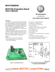
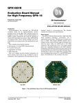
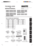
1
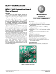
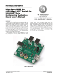
AP0100AT2L00XUGAH-GEVB
AP0100AT Evaluation Board
User's Manual
Evaluation Board Overview
The evaluation boards are designed to demonstrate the features of
ON Semiconductor’s image sensors products. This headboard is
intended to plug directly into the Demo 2× system. Test points and
jumpers on the board provide access to the clock, I/Os, and other
miscellaneous signals.
www.onsemi.com
EVAL BOARD USER’S MANUAL
Features
• Clock Input
♦
•
•
•
•
Default – 27 MHz Crystal Oscillator
Optional Demo 2× Controlled MClk
Two Wire Serial Interface
Parallel Interface
HiSPi (High Speed Serial Pixel) Interface
ROHS Compliant
♦
Figure 1. AP0100AT Evaluation Board
Block Diagram
Figure 2. Block Diagram of AP0100AT2L00XUGAH−GEVB
© Semiconductor Components Industries, LLC, 2015
September, 2015 − Rev. 0
1
Publication Order Number:
EVBUM2314/D
AP0100AT2L00XUGAH−GEVB
Top View
Headboard Connector J8
Headboard Connector J7
SEN_CLK P30
1OE/2OE P54
SEN_RST_OUT P51
EEPROM Sel P47, P48, P59
SEN_DATA P31
MCLK_IN P16
SPI_SDI_BAR P5
OSC/XTAL Sel P22, P23
VDD P26
SPI_SCLK/CS_N P44
Video Filter Sel P56, P57, P58
SPI Mem. Sel P7
TEST_BAR P3
ON_LED P11
GPIO1_LED P17
GPIO_DATA16 P37, P40, P41, P42
RESET Switch SW7
STANDBY P6
Figure 3. Top View of the Board with Default Jumpers
Bottom View
+HVDDIO P12
+AVDD P9
+SVDDIO P10
+3V3_VDDADAC P21
+VCC P14
+2V8_VDDPHY P20
HiSPi Connector J1
HiSPi Connector J2
Baseboard Connector J6
Baseboard Connector J5
Figure 4. Bottom View of the Board
www.onsemi.com
2
AP0100AT2L00XUGAH−GEVB
Jumper Pin Location
The jumpers on headboards start with Pin 1 on the
leftmost side of the pin. Grouped jumpers increase in pin
size with each jumper added.
Pin 1
Pins 1−4
Figure 5. Pin Locations for a Single Jumper. Pin 1 is Located at the Leftmost Side
and Increases as it Moves to the Right
Pin 1
Pins 1 and 2
Pins 3 and 4
Pins 5 and 6
Pins 7 and 8
Pins 9 and 10
Figure 6. Pin Locations and Assignments of Grouped Jumpers.
Pin 1 is Located at the Top-Left Corner and Increases in a Zigzag Fashion Shown in the Picture
Jumper/Header Functions & Default Positions
Table 1. JUMPERS AND HEADERS
Jumper/Header No.
Jumper/Header Name
Pins
P3
TRST_BAR
Open
P4
SADDR
Description
OTPM Programming Voltage Not Supplied
2−3 (Default)
P5
SPI_SDI_BAR
Set to Test Mode
Open
Analog Test 1 Header
1−2 (Default)
Open
P6
STANDBY
Set to Normal Mode
Open
GND; AP0100 in Host Mode
SPI_SDI_SEL; AP0100 in Flash Mode
2−3 (Default)
1−2
Active Mode
Standby Mode
I2C IO Expander Control
Open
P7
SPI Memory Selection
2−3 (Default)
EEPROM Disable/Flash Enable
Open
Flash Disable/EEPROM Enable
P8
GPIO_5
Open (Default)
P9
+AVDD
Set to Normal
2−3
Set to Vertical Flip
Closed (Default)
Open
P10
+SVDDIO
Serial IO Expander Control
1−2
Connects to On-Board Regulator +1V8, Internal
Regulator Use
Disconnects from On-Board Regulator +1V8, External
Regulator Use
3−5
Select Demo 3 Baseboard Clock
2−4
Select Slave Clock (for Slave Sensor in Multi-Camera
Mode)
www.onsemi.com
3
AP0100AT2L00XUGAH−GEVB
Table 1. JUMPERS AND HEADERS (continued)
Jumper/Header No.
Jumper/Header Name
Pins
Description
P11
ON_LED
1−2 (Default)
Connects to On-Board to Indicate Power On
P12
+HVDDIO
1−2 (Default)
Connects to On-Board +HVDDIO Power Supply
P14
+VCC
1−2 (Default)
2−3
External Power Supply Connection
2−3
P15
+5V0
External Power Supply Connection
1−2 (Default)
2−3
P16
MCLK_IN
P19
P20
GPIO1_LED
+AVDD
+2V8_VDDPHY
1−2 (Default)
+3V3_VDDADAC
Open (Default)
Off Frame LED
Closed
On Frame LED
Closed (Default)
Oscillator/Xtal
Selection
Disconnects from On-Board Regulator +1V8, External
Regulator Use
1−2 (Default)
Connects to On-Board +2V8_VDDPHY Power Supply
External Power Supply Connection
1−2 (Default)
P26
EXT_REG
VDD
Connects to On-Board +3V3_VDDADAC Power Supply
External Power Supply Connection
P22 1−2,
P23 Open (Default)
P22 2−3,
P23 Closed
P24
Connects to On-Board Regulator +1V8, Internal
Regulator Use
Open
2−3
P22, P23
Connects to On-Board Oscillator
Connects to XMCLK (i.e. Clock Signal from Demo2
Baseboard)
2−3
P21
USB +5V0_BUS Power Supply Connection
Connects to On-Board +5V0_EXT Power Supply
2−3
P17
Connects to On-Board +VCC Power Supply
Selects Oscillator as AP0100 Input Clock
Selects Crystal as AP0100 Input Clock
1−2 (Default)
Internal Regulator
2−3
External Regulator
1−2 (Default)
2−3
Internal Regulator +1V2_VDD
External On-Board Regulator U2 Set +1V2
P28
UART Transceiver
Open (Default)
Turn Off UART Transceiver
Closed
Turn On UART Transceiver
P30
SEN_CLK
Open (Default)
1−2
P31
SEN_DATA
Beagle Serial Access to Demo 2× & Sensor
Open (Default)
1−2
ENLDO
P33
GPIO1_LED
P34
GPIO_4
Open (Default)
P36
P37
GPIO_3
GPIO_2
GPIO_DATA16
Beagle Serial No Access to Demo 2× & Sensor
Beagle Serial Access to Demo 2× & Sensor
P32
P35
Beagle Serial No Access to Demo 2× & Sensor
1−2 (Default)
Enable Internal Regulator
2−3
Disable Internal Regulator
1−2
Set to GPI
2−3
Set to GPO
Serial IO Expander Control
1−2
Set to Normal
2−3
Set to Horizontal Mirror
Open (Default)
Serial IO Expander Control
1−2
Set to NTSC
2−3
Set to PAL
Open (Default)
Serial IO Expander Control
1−2
Set to No Pedestal
2−3
Set to Pedestal
1−2 (Default)
Open
Auto-Configuration Access
JTAG/UART Access
www.onsemi.com
4
AP0100AT2L00XUGAH−GEVB
Table 1. JUMPERS AND HEADERS (continued)
Jumper/Header No.
Jumper/Header Name
Pins
P38, P39
IO Expander U38
Setting
P39 Open,
P38 Closed (Default)
EEPROM Address Set to 0x48
P39 Open,
P38 Open
EEPROM Address Set to 0x4C
P39 Closed,
P38 Open
EEPROM Address Set to 0x44
P39 Closed,
P38 Closed
EEPROM Address Set to 0x40
1−2 (Default)
Auto-Configuration Access
P40
GPIO_DATA16
Description
Open
P41
GPIO_DATA16
JTAG/UART Access
1−2 (Default)
Open
JTAG/UART Access
P42
GPIO_DATA16
1−2 (Default)
P43
SP1_SDO/SDI
1−2 (Default)
P44
P44
SP1_SCLK/CS_N
1−2 (Default)
P45
SPI_SDI
Open
P50
SEN_SCLK
SEN_SDATA
Beagle SPI No Access to Sensor SPI
Beagle SPI Access to Sensor SPI
Open (Default)
1−2
P49
Beagle SPI No Access to Sensor SPI
Beagle SPI Access to Sensor SPI
Open
Serial I2C EEPROM
Address
Auto-Configuration Access
JTAG/UART Access
Open
P47, P48, P59
Auto-Configuration Access
Data or GND; AP0100 in Flash/Host Mode
High Z; AP0100 in Auto-Config Mode
P47 Closed,
P48 Open,
P59 Open
EEPROM Address Set to 0xAA (Default)
P47 Closed,
P48 Open,
P59 Open
EEPROM Address Set to 0xA2
P47 Open,
P48 Closed,
P59 Open
EEPROM Address Set to 0xA6
P47 Open,
P48 Open,
P59 Open
EEPROM Address Set to 0xAE
2−3 (Default)
AP0100 Serial Control
1−2
Demo 2× Serial Control
2−3 (Default)
AP0100 Serial Control
1−2
Demo 2× Serial Control
P51
SEN_RST_OUT
2−3 (Default)
AP0100 Reset
1−2
Demo 2× Reset
P52
BEAGLE_SCL
1−2 (Default)
P53
BEAGLE_SDA
1−2 (Default)
2−3
Sensor Accessed
2−3
P54
1OE/2OE
P56, P57, P58
Video Filter Selection
SW7
RESET
Demo 2× Accessed
Demo 2× Accessed
Sensor Accessed
1−2 (Default)
Enable Level Transistor U9
2−3
Disable Level Transistor U9
1−2 (Default)
Active Low Pass Filter
2−3
Discrete Low Pass Filter
N/A
When Pushed, 240 ms Reset Signal will be Sent to
AP0100 Chip
www.onsemi.com
5
AP0100AT2L00XUGAH−GEVB
Interfacing to ON Semiconductor Demo 3 Baseboard
The ON Semiconductor 2× baseboard has a similar 26-pin
connector and 13-pin connector which mate with J5 and J6
of the headboard. The four mounting holes secure the
baseboard and the headboard with spacers and screws.
ON Semiconductor and the
are registered trademarks of Semiconductor Components Industries, LLC (SCILLC) or its subsidiaries in the United States and/or other countries.
SCILLC owns the rights to a number of patents, trademarks, copyrights, trade secrets, and other intellectual property. A listing of SCILLC’s product/patent coverage may be accessed
at www.onsemi.com/site/pdf/Patent−Marking.pdf. SCILLC reserves the right to make changes without further notice to any products herein. SCILLC makes no warranty, representation
or guarantee regarding the suitability of its products for any particular purpose, nor does SCILLC assume any liability arising out of the application or use of any product or circuit, and
specifically disclaims any and all liability, including without limitation special, consequential or incidental damages. “Typical” parameters which may be provided in SCILLC data sheets
and/or specifications can and do vary in different applications and actual performance may vary over time. All operating parameters, including “Typicals” must be validated for each
customer application by customer’s technical experts. SCILLC does not convey any license under its patent rights nor the rights of others. SCILLC products are not designed, intended,
or authorized for use as components in systems intended for surgical implant into the body, or other applications intended to support or sustain life, or for any other application in which
the failure of the SCILLC product could create a situation where personal injury or death may occur. Should Buyer purchase or use SCILLC products for any such unintended or
unauthorized application, Buyer shall indemnify and hold SCILLC and its officers, employees, subsidiaries, affiliates, and distributors harmless against all claims, costs, damages, and
expenses, and reasonable attorney fees arising out of, directly or indirectly, any claim of personal injury or death associated with such unintended or unauthorized use, even if such claim
alleges that SCILLC was negligent regarding the design or manufacture of the part. SCILLC is an Equal Opportunity/Affirmative Action Employer. This literature is subject to all applicable
copyright laws and is not for resale in any manner.
PUBLICATION ORDERING INFORMATION
LITERATURE FULFILLMENT:
Literature Distribution Center for ON Semiconductor
19521 E. 32nd Pkwy, Aurora, Colorado 80011 USA
Phone: 303−675−2175 or 800−344−3860 Toll Free USA/Canada
Fax: 303−675−2176 or 800−344−3867 Toll Free USA/Canada
Email: [email protected]
N. American Technical Support: 800−282−9855 Toll Free
USA/Canada
Europe, Middle East and Africa Technical Support:
Phone: 421 33 790 2910
Japan Customer Focus Center
Phone: 81−3−5817−1050
www.onsemi.com
6
ON Semiconductor Website: www.onsemi.com
Order Literature: http://www.onsemi.com/orderlit
For additional information, please contact your local
Sales Representative
EVBUM2314/D