1
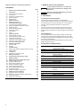
GRUNDFOS INSTRUCTIONS
Grundfos CIU 200
Modbus RTU for Grundfos CR Monitor
Functional profile and user manual
1. Symbols used in this document
Original installation and operating instructions.
CONTENTS
Page
Caution
If these safety instructions are not observed,
it may result in malfunction or damage to the
equipment!
Note
Notes or instructions that make the job easier
and ensure safe operation.
1.
Symbols used in this document
2
2.
2.1
2.2
2.3
2.4
2.5
Introduction
About this functional profile
Assumptions
Definitions and abbreviations
System diagrams
Specifications
2
2
2
2
3
4
2. Introduction
3.
3.1
Modbus interface
Modbus bus topology
5
5
This functional profile describes the CIU 200 (Modbus
Communication Interface Unit 200) for the Grundfos CR Monitor.
4.
4.1
4.2
4.3
4.4
4.5
4.6
4.7
CIM 200 Modbus module
Connecting to the Modbus network
Setting the Modbus transmission speed
Setting the parity
Modbus address selection
Termination resistor
Cable length
LEDs
5
6
6
6
7
7
7
7
5.
5.1
5.2
5.3
5.4
5.5
5.6
Functional profile
Register block overview
CIM configuration register block
CIM status register block
CR Monitor control register block
CR Monitor status register block
CR Monitor data register block
8
8
8
9
9
10
13
6.
6.1
6.2
Detailed descriptions
Control modes
Setpoint
14
14
15
7.
7.1
Commissioning
Step-by-step guide to hardware setup (CIU 200)
16
16
8.
8.1
8.2
Fault finding
LED Status
Modbus communication faults
16
16
17
9.
Data item overview
18
10.
Grundfos alarm and warning codes
20
11.
Modbus address
22
12.
12.1
12.2
12.3
12.4
12.5
12.6
12.7
12.8
Modbus telegrams and function codes
Modbus telegram overview
Function code overview
Read holding registers (0x03)
Read input registers (0x04)
Write single register (0x06)
Write multiple registers (0x10)
Diagnostics (0x08)
Diagnostics register interpretation
23
23
23
24
24
24
25
26
27
13.
13.1
13.2
13.3
13.4
Modbus telegram examples
Diagnostics return query data
Reading the CIM configuration register block
Setting the setpoint
Setting the control mode
28
28
28
28
28
2
2.1 About this functional profile
In the following, the CIU 200 is referred to as "communication
interface", and the Grundfos CR Monitor is referred to as
"controller".
The data in this document are subject to change without prior
notice. Grundfos cannot be held responsible for any problems
caused directly or indirectly by using information in this functional
profile.
2.2 Assumptions
This functional profile assumes that the reader is familiar with
commissioning and programming Modbus devices. The reader
should also have some basic knowledge of the Modbus protocol
and technical specifications.
It is also assumed that an existing Modbus RTU network with a
Modbus master is present.
2.3 Definitions and abbreviations
CIM 200
Communication Interface Module
(built into the CIU 200)
CIU 200
Communication Interface Unit
CR
Grundfos multistage centrifugal pump
CRC
Cyclic Redundancy Check, a data error
detection method
CRE
Grundfos multistage centrifugal pump
with variable-speed motor
Derivation cable
Stub cable
GENIbus
Proprietary Grundfos fieldbus standard
H
Pressure (Head)
IO 351
Grundfos Input/Output module
LED
Light-Emitting Diode
Modbus
A serial communications protocol
commonly used in industry and building
services
MP 204
Electronic Grundfos Motor Protector
Q
Flow
RTU
Remote Terminal Unit
Transmission speed
Bits transferred per second
Trunk cable
Main RS-485 cable on Modbus network
2.4 System diagrams
The CR Monitor offers advanced monitoring of a Grundfos
CRE pump or a Grundfos MP 204 motor protector connected to a
CR pump.
The system diagrams give an overview of how to connect the
CIU 200 to the Grundfos CR Monitor that is to be connected to a
Modbus network. A CR Monitor is connected to either a
CRE pump or an MP 204 connected to a CR pump. The CIU 200
has a number of sensor inputs that can be connected directly to
sensors, or it can get sensor inputs from a Grundfos IO 351
module.
The CIU 200 offers a Modbus RTU connection to the CR Monitor.
Note that the CR Monitor must have a GENIbus RS-485 module
installed.
The CIU 200 solution is a box with a power supply module and a
CIM 200 module. The CIU 200 can either be mounted on a
DIN rail or on a wall. See fig. 1 or 2.
Modbus
Modbus
RTU
RTU
CIU
GENIbus
GENIbus
RS-485
RS-485
CR Monitor
CR
Monitor
GENIbus
GENIbuss
RS-485
RS-485
CRE
CRE
Sensorinputs
inputs
Sensor
Fig. 1
TM04 4278 1109
GrundfosCR
CR Monitor
Monitor and
CRE
Grundfos
and
CRE
CR Monitor connected to a CRE pump
Grundfos CR Monitor and MP 204 with CR
Modbus
Modbus
RTU
RTU
GENIbus
GENIbus
GENIbus
GENIbus
RS-485
RS-485
RS-485
RS-485 MP 204
CIU
CR Monitor
CIU
CR
Monitor
MP
204
motor
motor
or
protector
protector
Sensor
Sensorinputs
inputs
CR
CR
Fig. 2
TM04 4279 1109
Grundfos CR Monitor and MP 204 with CR
CR Monitor connected to an MP 204 which is
connected to a CR pump
3
2.5 Specifications
The table below gives an overview of the specifications for the Grundfos CIU 200. For further details, please refer to the specific sections
of this functional profile.
General data
GENIbus visual diagnostics
LED2
Off, constantly green, flashing red, constantly red.
See section 4.7.2 LED2, internal communication.
Communication Interface Unit (CIU 200)
Power supply
24-240 V
GENIbus connection type
RS-485
GENIbus wire configuration
Three-wire + screen
Located in the CIU 200.
Conductors: A, B and Y.
Modbus specifications
Data protocol
Modbus RTU
Modbus connector
Screw-type terminal
Modbus connection type
RS-485
Modbus wire configuration
Two-wire + common
3 pins. See section 4. CIM 200 Modbus module.
Conductors: D0, D1 and Common.
See section 4.1 Connecting to the Modbus
network.
Maximum trunk cable length
1200 m
Equals 4000 ft.
Maximum derivation cable length
250 m (at 38400 bits/s)
Equals 820 ft.
Slave address
1-247
Set via rotary switches SW6 and SW7.
See section 4.4 Modbus address selection.
Line termination
On or Off
Set via DIP switches SW1 and SW2.
See section 4.5 Termination resistor.
Supported transmission speeds
1200*, 2400*, 4800*, 9600, 19200,
38400 bits/s
Set via DIP switches SW4 and SW5.
See section 4.2 Setting the Modbus transmission
speed.
(*Can only be set by software).
Start bit
1
Fixed value.
Data bits
8
Fixed value.
Stop bits
1 or 2
Set via DIP switch SW3.
See section 4.3 Setting the parity.
Parity bit
Even parity or no parity
Set via DIP switch SW3.
See section 4.3 Setting the parity.
Modbus visual diagnostics
LED1
Off, constantly green, flashing red, constantly red.
See section 4.7.1 LED1, Modbus communication.
Maximum number of Modbus devices
32
Using repeaters, this number can be increased.
Address range is 1-247.
4
3. Modbus interface
4. CIM 200 Modbus module
3.1 Modbus bus topology
The Grundfos CIM/CIU 200 is connected as a Modbus slave
directly to the Modbus RTU network. This is done either in daisy
chain style, or using a passive TAP and a derivation cable (stub).
Both methods are exemplified below.
Master
Passive TAP*
8
Slave
Example of Modbus network with termination
In such a network, only one master device is connected to the
serial bus, and one or several (maximum 247) slaves are also
connected to the serial bus. Slaves cannot communicate with
each other and will never transmit data without receiving a
request from the master device.
Up to 32 devices can be connected to one RS-485 Modbus
system without using a repeater. To implement a larger number of
devices, use a repeater to connect the smaller networks to larger
networks. Repeaters are also used to extend the maximum
transmission distance.
Fig. 4
Pos.
4
5
6
7
TM04 1697 0908
1 2 3
LT = Line Termination
(termination resistor)
Fig. 3
9
TM04 1947 1508
Slave
Slave
Daisy chain
Slave
Slave
CIM 200 Modbus module
Designation
Description
1
D1
Modbus terminal D1
(positive data signal)
2
D0
Modbus terminal D0
(negative data signal)
3
Common/GND
Modbus terminal
Common/GND
4
SW1/SW2
On/off switches for termination
resistor
5
SW3/SW4/SW5
Switches for selection of Modbus
parity and transmission speed
6
LED1
Red/green status LED for Modbus
communication
7
LED2
Red/green status LED for internal
communication between the
CIM 200 and the CR Monitor
8
SW6
Hex switch for setting the Modbus
address (four most significant bits)
9
SW7
Hex switch for setting the Modbus
address (four least significant bits)
5
4.1 Connecting to the Modbus network
4.3 Setting the parity
A screened, twisted-pair cable must be used. The cable screen
must be connected to protective earth at both ends.
The parity can be set either manually by using SW3 or via
software-defined settings.
Recommended connection
Manual setting of parity
Colour code
Data signal
The CIM 200 only supports the Modbus RTU mode and hence
cannot communicate with Modbus ASCII mode devices.
D1-TXD1
Yellow
Positive
Default byte format (11 bits):
D0-TXD0
Brown
Negative
•
1 start bit
Common/GND
•
8 data bits (least significant bit sent first)
•
1 parity bit (even parity)
4.2 Setting the Modbus transmission speed
•
1 stop bit.
The transmission speed must be set correctly before the CIM 200
Modbus module is ready to communicate with the Modbus
network. DIP switches SW4 and SW5 are used for setting the
transmission speed. See fig. 5.
The default setting of the CIM 200 Modbus module is even parity
(1 stop bit). It is possible to change the parity with DIP switch
SW3. The parity can be changed to no parity (2 stop bits).
See fig. 6.
Grey
TM04 1710 0908
Common
SW4 SW5
Fig. 5
Modbus transmission speed setting
SW3
Fig. 6
4.2.1 DIP switch settings
TM04 1709 0908
Modbus terminal
Parity
DIP switch settings
Available transmission speeds in bits/s: 1200, 2400, 4800, 9600,
19200 and 38400.
The first three transmission speeds are only available via
software settings, whereas the last three are available via
DIP switches SW4 and SW5.
Parity
SW3
Even parity, 1 stop bit
OFF
No parity, 2 stop bits
ON
Software-defined parity and stop bit
Transmission speed
SW4
SW5
9600 bits/s
OFF
ON
19200 bits/s
OFF
OFF
38400 bits/s
ON
OFF
Software-defined
ON
ON
When SW4 and SW5 are set to "software-defined", the value in
holding registers at addresses 00009 and 00010 will override the
setting of SW3. See figs 5 and 6.
Software-defined parity
Set register value
00009
The default transmission speed is 19200 bits per second, as per
the Modbus RTU standard.
No parity [default]
Even parity
1
The transmission speed will be effective immediately after setting
the values of the DIP switch.
Odd parity
2
Software-defined
When SW4 and SW5 are set to "software-defined", writing a
value to the holding register at address 00004 will set a new
transmission speed.
Use the following values for software-defined transmission
speeds:
Software-defined transmission
speed
0
2400 bits/s
1
4800 bits/s
2
9600 bits/s
3
19200 bits/s
4
38400 bits/s
5
This value is set to 1200 bits/s as default.
The communication interface does not support transmission
speeds above 38400 bits/s.
The software-defined transmission speed value will be stored
in the communication interface and will remain after a power-off.
6
When software-defined transmission speed is
enabled (ON), software-defined parity and stop
bit are also enabled.
Set register value
00010
1 stop bit [default]
1
2 stop bits
2
The software-defined parity and stop bit values will be stored in
the communication interface and will remain after a power-off.
Set register value
00004
1200 bits/s
Note
Software-defined stop bit
0
Note
Before the parity and stop bit can be set via
software-defined settings, SW4 and SW5 must be
set to ON.
4.4 Modbus address selection
4.7 LEDs
A Modbus slave on a Modbus network must have a unique
address from 1 to 247. Address 0 is reserved for broadcasting,
and is not a valid slave address.
The CIM/CIU 200 has two LEDs.
•
Red/green status LED (LED1) for Modbus communication
between master and slave
To set the Modbus address, two hexadecimal rotary switches
(SW6 and SW7) are used. See fig. 7.
•
Red/green status LED (LED2) for internal communication
between the CIM/CIU 200 and the CR Monitor.
SW6
Fig. 7
TM04 1706 0908
4.7.1 LED1, Modbus communication
SW7
Setting the Modbus address
For a complete overview of Modbus addresses, see section
11. Modbus address on page 22.
4.5 Termination resistor
The termination resistor is fitted on the CIM 200 Modbus module
and has a value of 150 Ω.
TM04 1701 0908
The CIM 200 has a DIP switch with two switches (SW1 and SW2)
for cutting the termination resistor in and out. Figure 8 shows the
DIP switches in cut-out state.
SW1 SW2
Fig. 8
Cutting the termination resistor in and out
DIP switch settings
Status
SW1
Cut-in
Cut-out
Description
Off
No Modbus communication.
Flashing green
Modbus communication active.
Flashing red
Fault in the Modbus communication.
Constantly red
Fault in the CIM 200 Modbus configuration.
4.7.2 LED2, internal communication
The Modbus address must be set decimally from
1 to 247.
Note
Status
Status
Description
Off
The CIM/CIU 200 has been switched off,
or is starting up.
Flashing red
No internal communication between the
CIM/CIU 200 and the CR Monitor.
Constantly red
The CIM/CIU 200 does not support the
CR Monitor connected.
Constantly green
Internal communication between the
CIM/CIU 200 and the CR Monitor is OK.
Note
During start-up, there may be a delay of up to
5 seconds before the LED2 status is updated.
Note
The CR Monitor must have finished its start-up
sequence before the LED2 can be used for
status. This means that a certain delay may occur
before the LED2 turns green after start-up of the
CR Monitor.
SW2
ON
ON
OFF
OFF
ON
OFF
OFF
ON
Default setting: Termination resistor cut-out.
4.6 Cable length
The trunk cable must not exceed a total length of 1,200 m
(4,000 ft).
Grundfos recommends the following maximum cable lengths:
Maximum cable length
bits/s
Terminated cable
Unterminated cable
[m/ft]
[m/ft]
9600 bits/s
1200/4000
1200/4000
19200 bits/s
1200/4000
500/1700
38400 bits/s
1200/4000
250/800
Note
To ensure a stable and reliable communication,
it is important that only the termination resistor
of the first and last units in the Modbus network
are cut in. See fig. 3.
7
5. Functional profile
5.1 Register block overview
The Modbus RTU registers are grouped in the following register blocks:
Start address
Register block
Permissions Description
00001
CIM configuration
R/W
Configuration of the CIM module.
00021
CIM status
R
Status registers for the CIM module.
00101
CR Monitor control
R/W
Registers for control of the CR Monitor and the pump.
00201
CR Monitor status
R
Registers for reading mode status from the CR Monitor and the pump.
00301
CR Monitor data
R
Registers for reading measured data values from the CR Monitor and the
pump.
All addresses contain registers. Some are bit-interpreted while others are 16-bit values, or part of 32-bit values.
5.2 CIM configuration register block
Registers in this block can be read by means of function codes 0x03 and/or 0x04. They can be written as holding registers with function
codes 0x06 and 0x10.
Address
Register name
Description
SlaveMinimumReplyDelay
The minimum reply delay from the slave in ms.
Value range: 0-10000, i.e. up to 10 seconds reply delay. This delay is typically used in
conjunction with a modem. The delay value is stored in the device and will remain after
a power-off. The delay set here will be added to the internal delay in the device.
Default value is 0.
00002
RegisterOffset
An address offset that is added to all addresses above 00100.
Default value is 0.
Note: This offset does not affect the CIM configuration register block or the CIM status
register block addresses. The register offset value is stored in the device and will remain
after a power-off.
For most applications, this offset should not be changed.
00003
If the Modbus address switch has not been set correctly, i.e. not within the 1 to 247 range,
the value in this register is used as Modbus address.
SoftwareDefinedModbusAddress See section 4.4 Modbus address selection.
The value is stored in the device and will remain after a power-off.
Default value of this register is 0xE7 (231).
00004
SoftwareDefinedBitRate
Modbus software-defined transmission speed enumeration.
The software-defined transmission speed value is stored in the device and will remain
after a power-off.
0 = 1200 bits/s
1 = 2400 bits/s
2 = 4800 bits/s
3 = 9600 bits/s
4 = 19200 bits/s
5 = 38400 bits/s.
Note: This value is used only when the transmission speed is set to "software-defined" on
the DIP switches SW4 and SW5. Otherwise, it will be ignored by the slave.
00005
AutoAckControlBits
Used to select the behaviour of control bit acknowledgements from the CIU 200.
0 = Disabled.
Control bits are not automatically lowered when accepted by the device. The user must
lower the triggered control bit manually before the control bit can be triggered again.
1 = Enabled.
Control bits are automatically lowered when accepted by the device. The user does not
have to lower it manually [default].
00006
RESERVED
-
00007
RESERVED
-
00008
RESERVED
-
00009
SoftwareDefinedParity
Parity setting to be used when using "software-defined" settings.
0 = No parity [default]
1 = Even parity
2 = Odd parity.
00010
SoftwareDefinedStopBit
Stop bit setting to be used when using "software-defined" settings.
0 = No stop bit
1 = 1 stop bit [default]
2 = 2 stop bits.
00001
8
5.3 CIM status register block
Registers in this block can be read by means of function codes 0x03 and/or 0x04. They are read-only. This block can be used for various
kinds of fault finding.
Address
Register name
Description
00021
GrundfosCRCErrorCnt
Holds a CRC error counter for the GENIbus connection between the CIU 200 and the
CR Monitor.
00022
GrundfosDataErrorCnt
Holds a data error counter for the GENIbus connection between the CIU 200 and the
CR Monitor.
00023
VersionNumber
A Grundfos-specific version number. This is an unsigned integer value.
00024
ActualModbusAddress
Holds the current Modbus slave address of the device.
Valid value range: 1…247.
00025
00026
GrundfosTXcountHI
GrundfosTXcountLO
Holds a transmit counter for total number of telegrams sent to the CIU 200 on the GENIbus
connection.
00027
00028
GrundfosRXcountHI
GrundfosRXcountLO
Holds a receive counter for total number of telegrams received from the CIU 200 on the
GENIbus connection.
00029
RESERVED
-
00030
UnitFamily
Grundfos product family.
00031
UnitType
Grundfos product type.
00032
UnitVersion
Grundfos product version.
5.4 CR Monitor control register block
Registers in this block can be read by means of function codes 0x03 and/or 0x04. They can be written as holding registers with function
codes 0x06 and 0x10.
Address
Register name
Description
ControlRegister
Bits 3-15: RESERVED
-
ControlRegister
Bit 2: ResetAlarm
Control bit that resets alarms and warnings.
0 = No resetting
1 = Resetting alarm.
This control bit is triggered on rising edge only, i.e. setting logical 0 to 1.
See section 5.2 CIM configuration register block, address 00005, for acknowledgement
behaviour.
ControlRegister
Bit 1: OnOffReq
Control bit that switches the pump/MP 204 on and off.
0 = Off (stop)
1 = On (start).
ControlRegister
Bit 0: RemoteAccessReq
Control bit that sets local or remote control.
0 = Local
1 = Remote (controlled by Modbus master).
This bit must be 1 if the pump/MP 204 is to be controlled by a Modbus master.
ControlMode
Sets the control mode enumeration.
0 = CONST_SPEED (constant speed)
1 = CONST_FREQ (constant frequency)
3 = CONST_HEAD (constant head)
4 = CONST_PRESSURE (constant pressure)
5 = CONST_DIFFPRESS (constant differential pressure)
6 = VAR_DIFFPRESS (variable differential pressure)
7 = CONST_FLOW (constant flow)
8 = CONST_TEMP (constant temperature)
10 = CONST_LEV (constant level)
128 = AUTO_PRESS_MODE (automatic mode).
See section 6.1 Control modes for details.
OperationMode
A state enumeration to control the pump operating mode.
0 = Auto-control (setpoint control)
4 = OpenLoopMin (running at minimum speed)
6 = OpenLoopMax (running at maximum speed).
Note: OnOffReq has higher priority than the OperationMode, meaning that OnOffReq must be
set to on for the OperationMode to have any effect.
See section 6.1 Control modes for details.
Setpoint
Sets the pump setpoint (not used on systems with MP 204).
Scale is 0.01 %, with value range [0; 10000].
Closed loop
Percentage of closed-loop feedback sensor range.
Open loop
Percentage of pump performance.
Common examples
4700 = 47 %
8000 = 80 %.
See section 6.2 Setpoint.
00101
00102
00103
00104
9
5.5 CR Monitor status register block
Registers in this register block can be read by means of function codes 0x03 and/or 0x04. They are read-only.
Address
00201
00202
00203
10
Register name
Description
StatusRegister
Bit 15: AtMinSpeed
Indicates if the CRE pump is running at minimum speed.
0 = No
1 = Yes.
Not available on the CR pump.
StatusRegister
Bit 14: RESERVED
-
StatusRegister
Bit 13: AtMaxSpeed
Indicates if the CRE pump is running at maximum speed.
0 = No
1 = Yes.
Not available on the CR pump.
StatusRegister
Bit 12: RESERVED
-
StatusRegister
Bit 11: Warning
Indicates if there is a warning or not. The pump will continue running even if there is a
warning.
0 = No warning
1 = Warning.
StatusRegister
Bit 10: Fault
Indicates if there is a fault or not.
0 = No fault
1 = Fault.
StatusRegister
Bit 9: OnOff
Indicates if the pump is on or not.
0 = Off (stopped)
1 = On (started).
Started does not necessarily indicate rotation, for instance in case of low-flow stop.
StatusRegister
Bit 8: AccessMode
Indicates if the pump is locally or remotely controlled.
0 = Local (a local control source with higher priority controls the pump).
1 = Remote (controlled by Modbus master).
StatusRegister
Bit 7: RESERVED
-
StatusRegister
Bit 6: Rotation
Indicates if the pump is rotating (running) or not.
0 = No rotation
1 = Rotation.
StatusRegister
Bits 4-5: RESERVED
-
StatusRegister
Bit 3: ResetAlarmAck
Indicates if a ResetAlarm was acknowledged by the device. This bit will be set when the
CIU 200 has accepted the ResetAlarm control bit, and the user can clear the ResetAlarm bit.
The CIU 200 will automatically clear the ResetAlarmAck bit to 0 when the user clears the
ResetAlarm bit, and a new ResetAlarm can be attempted by raising the ResetAlarm control bit
again.
0 = No acknowledgement
1 = Control bit acknowledged.
This functionality is only used when AutoAckControlBits is disabled.
See section 5.2 CIM configuration register block.
StatusRegister
Bits 0-2: RESERVED
-
ProcessFeedback
Indicates the actual process feedback from the CRE pump.
The scale is 0.01 %, so the valid value range is from 0 to 10000.
This value can be compared with the setpoint value.
Closed loop
Percentage of closed-loop feedback sensor range.
Open loop
Percentage of CRE pump performance.
Common examples
4700 = 47 %
8000 = 80 %.
ControlMode
Indicates the actual control mode.
0 = CONST_SPEED (constant speed)
1 = CONST_FREQ (constant frequency)
3 = CONST_HEAD (constant head)
4 = CONST_PRESSURE (constant pressure)
5 = CONST_DIFFPRESS (constant differential pressure)
6 = VAR_DIFFPRESS (variable differential pressure)
7 = CONST_FLOW (constant flow)
8 = CONST_TEMP (constant temperature)
10 = CONST_LEV (constant level)
128 = AUTO_PRESS_MODE (automatic mode).
Address
Register name
Description
OperationMode
Indicates the actual operating mode.
0 = Auto-control (setpoint control)
4 = OpenLoopMin (running at minimum speed)
6 = OpenLoopMax (running at maximum speed).
00205
AlarmCode
The Grundfos-specific alarm code. See section 10. Grundfos alarm and warning codes.
00206
WarningCode
The Grundfos-specific warning code. See section 10. Grundfos alarm and warning codes.
00204
Bits 9-15: RESERVED
-
Bit 8: BearingServiceType
Indicates the type of the next bearing service.
0 = Lubricate bearings
1 = Change bearings.
Bits 0-7:
MonthsToBearingService
Indicates the number of months until the next bearing service.
This value can be 0, 1, 3, 6, 12 and 24 months, if available. A value of 24 months means
"24 months or more". A value of 0xFF indicates that the information is not available.
00208.0
MonitorLearningActivated
Indicates the activation status of the CR Monitor learning function.
0 = Not activated
1 = Activated.
00208.1
MonitorLearningOperating
Indicates the operating status of the CR Monitor learning function.
0 = Not operating
1 = Operating.
00208.2
MonitorLearningDataQuality
Indicates the data stability of the CR Monitor learning function.
0 = Unstable data
1 = Stable data.
ControllerFaults
Indicates controller faults.
Bit 0: RESERVED
Bit 1: FLASH parameter verification error (code 83)
Bit 2: Ethernet: No IP address from DHCP server (code 231)
Bit 3: Ethernet: Auto-disabled due to misuse (code 232).
MonitorAlarms1
Alarm bits for the monitoring system.
Bit 0: Maximum inlet pressure alarm limit exceeded
Bit 1: Minimum inlet pressure alarm limit exceeded
Bit 2: Maximum discharge pressure alarm limit exceeded
Bit 3: Minimum discharge pressure alarm limit exceeded
Bit 4: Maximum differential-pressure alarm limit exceeded
Bit 5: Minimum differential-pressure alarm limit exceeded
Bit 6: Maximum flow alarm limit exceeded
Bit 7: Minimum flow alarm limit exceeded
Bit 8: Maximum supply voltage alarm limit exceeded
Bit 9: Minimum supply voltage alarm limit exceeded
Bit 10: Maximum speed alarm limit exceeded
Bit 11: Minimum speed alarm limit exceeded
Bit 12: Maximum power alarm limit exceeded
Bit 13: Minimum power alarm limit exceeded
Bit 14: Minimum efficiency alarm limit exceeded
Bit 15: Minimum cavitation alarm limit exceeded.
MonitorAlarms2
Alarm bits for the monitoring system.
Bit 0: Maximum Q, H alarm limit exceeded
Bit 1: Maximum Q, P alarm limit exceeded
Bit 2: Start trip counter alarm limit exceeded
Bit 3: Maximum lubrication time alarm limit exceeded
Bit 4: RESERVED
Bit 5: RESERVED
Bit 6: Pump fault
Bits 7-15: RESERVED.
MonitorWarnings1
Warning bits for the monitoring system.
Bit 0: Maximum inlet pressure warning limit exceeded
Bit 1: Minimum inlet pressure warning limit exceeded
Bit 2: Maximum discharge pressure warning limit exceeded
Bit 3: Minimum discharge pressure warning limit exceeded
Bit 4: Maximum differential-pressure warning limit exceeded
Bit 5: Minimum differential-pressure warning limit exceeded
Bit 6: Maximum flow warning limit exceeded
Bit 7: Minimum flow warning limit exceeded
Bit 8: Maximum supply voltage warning limit exceeded
Bit 9: Minimum supply voltage warning limit exceeded
Bit 10: Maximum speed warning limit exceeded
Bit 11: Minimum speed warning limit exceeded
Bit 12: Maximum power warning limit exceeded
Bit 13: Minimum power warning limit exceeded
Bit 14: Minimum efficiency warning limit exceeded
Bit 15: Minimum cavitation warning limit exceeded.
00207
00209
00210
00211
00212
11
Address
00213
00214
00215
12
Register name
Description
MonitorWarnings2
Warning bits for the monitoring system.
Bit 0: Maximum Q, H warning limit exceeded
Bit 1: Maximum Q, P warning limit exceeded
Bit 2: Start trip counter warning limit exceeded
Bit 3: Maximum lubrication time warning limit exceeded
Bit 4: RESERVED
Bit 5: RESERVED
Bit 6: Pump warning
Bits 7-15: RESERVED.
MP 204Warnings1
Warning bits for MP 204, if installed.
Bit 0: Maximum voltage warning
Bit 1: Minimum voltage warning
Bit 2: Maximum line current warning
Bit 3: Minimum line current warning
Bit 4: Line current asymmetry warning
Bit 5: RESERVED
Bit 6: RESERVED
Bit 7: RESERVED
Bit 8: Insulation resistance warning
Bit 9: Motor temperature (Tempcon) warning
Bit 10: Motor temperature (PT resistor) warning
Bit 11: RESERVED
Bit 12: Maximum cos φ warning limit exceeded
Bit 13: Minimum cos φ warning limit exceeded
Bit 14: Starts per hour warning
Bit 15: Starts per hour warning limit exceeded.
MP 204Warnings2
Warning bits for MP 204, if installed.
Bit 0: Start capacitor min. warning
Bit 1: RESERVED
Bit 2: Run capacitor min. warning
Bit 3: Tempcon sensor signal fault warning
Bit 4: Pt sensor signal fault warning
Bit 5: Service warning: t_run_trip_cnt > t_run_trip_warn
Bit 6: Load continues even if the motor has been switched off
Bits 7-15: RESERVED.
5.6 CR Monitor data register block
Registers in this block can be read by means of function codes
0x03 and/or 0x04. They are read-only. The table below shows the
availability of the data, depending on system configuration.
Address
Register name
Scale
00301
InletPressure (offset = 1 bar)
0.001 bar
00302
OutletPressure
0.001 bar
00303
VolumeFlow
0.1 m3/h
00304
Speed
1 rpm
00305
Frequency
0.1 Hz
00306
DigitalInput
bits
00307
DigitalOutput
bits
00308
ActualSetpoint
Available with CRE pump only.
0.01 %
00309
MotorCurrent
0.1 A
00310
MotorTemp
Available if a Pt100 sensor is used.
0.01 K
00311
MotorVoltage
0.1 V
00312
CalculatedPower
1W
00313
00314
PowerHI
PowerLO
1W
00315
PumpLiquidTemp
0.01 K
00316
AuxSensorInput
0.01 %
00317
00318
OperationTimeHI
OperationTimeLO
1 hour
00319
00320
TotalPoweredTimeHI
TotalPoweredTimeLO
1 hour
00321
00322
EnergyHI
EnergyLO
1 kWh
00323
00324
NumberOfStartsHI
NumberOfStartsLO
1 start
00325
DifferentialPressure
0.001 bar
00326
CalculatedDifferentialPressure
0.001 bar
00327
CalculatedEfficiency
0.01 %
00328
MeasuredEfficiency
0.01 %
00329
NPSHAvailable
0.01 m
00330
NPSHRequired
0.01 m
00331
CavitationMargin
0.01 m
A data value of 0xFFFF indicates "not available".
See section 9. Data item overview for more information on this
register block.
13
6. Detailed descriptions
6.1 Control modes
The supported control modes are described further in this section.
> CONST_SPEED
> CONST_FREQ
Open loop
The setpoint of the CRE pump will be interpreted as setpoint
for the pump speed.
The setpoint value is a percentage of the maximum speed of
the pump.
No sensor is required in these modes.
Illustration
H
Q
> CONST_HEAD
> CONST_PRESSURE
> CONST_DIFFPRESS
Closed loop
The setpoint of the CRE pump will be interpreted as setpoint
for the pressure.
The controller in the pump will change the pump speed so that
the pressure is constant, regardless of the flow.
A pressure sensor is required.
H
Q
> VAR_DIFFPRESS
Closed loop
The setpoint of the CRE pump will be interpreted as basic
setpoint for the VAR_DIFFPRESS mode (the black dot in the
drawing). This control mode is only available on TPE Series
2000 pumps.
A pressure sensor is required.
H = Pressure (Head)
Q = Flow
14
H
Q
TM04 2288 2208
Closed loop
The setpoint of the CRE pump will be interpreted as setpoint
for the flow, temperature or level. CONST_FLOW is illustrated
to the right.
A relevant sensor is required:
• a temperature sensor for temperature control,
• a level sensor for level control and
• a flow sensor for flow control.
Q
TM04 2291 2208
> CONST_FLOW
> CONST_TEMP
> CONST_LEV
TM04 2289 2208
Description
TM04 2290 2208
Control modes
H
6.2 Setpoint
This register accepts values ranging from 0 to 10000 (0 % to
100 %). This is illustrated in fig. 9. The setpoint is a percentage of
the maximum setpoint or sensor maximum (max. = 100 %).
The setpoint value can represent speed, pressure, flow, etc.,
depending on the selected control mode.
A setpoint of 0 does not imply a stop.
Minimum
setpoint
0=0%
Fig. 9
Setpoint [%]
10000 = 100 %
TM04 2373 2508
Effective setpoint
Sensor
maximum
Setpoint
6.2.1 Control modes
Closed loop
If the control mode is set to CONST_PRESS (closed loop), and
the pressure sensor is in the range of 0 to 10 bar, a setpoint of
80 % will result in an effective setpoint of 8 bar.
If the sensor range was 0-16 bar, a 50 % setpoint would be 8 bar,
a 25 % setpoint would be 4 bar, and so on.
10 bar
0=0%
8000 = 80 %
10000 = 100 %
TM04 2371 2508
8 bar
Fig. 10 Constant pressure
Open loop
If the control mode is set to CONST_FREQ (open loop), the
setpoint is interpreted as setpoint for the system performance.
The example shows that a 50 % setpoint equals a 50 % system
performance.
Maximum
system
performance
0=0%
5000 = 50 %
10000 = 100 %
TM04 2372 2508
50 % system
performance
Fig. 11 Constant frequency
15
7. Commissioning
Note
If the sensor configuration is changed, restart the CIU 200 to ensure a correct scaling of the sensor value.
7.1 Step-by-step guide to hardware setup (CIU 200)
Step
Description
1
Complete the CR Monitor system configuration, e.g. sensor configuration.
2
Select the Modbus slave address (1-247). See section 4.4 Modbus address selection.
3
Select the transmission speed of the Modbus slave. See section 4.2 Setting the Modbus transmission speed.
4
Select parity and stop bits of the Modbus slave (even-1 or none-2). See section 4.3 Setting the parity.
5
If necessary, set line termination. See section 4.5 Termination resistor.
6
Connect the GENIbus cable from the CIU 200 to the CR Monitor.
7
Connect the necessary cables from the CIU 200 to the Modbus network. See section 4.1 Connecting to the Modbus network.
8
Connect the power supply cable to the CIU 200, and switch the unit on.
9
Confirm that the GENIbus LED is constantly green and that the Modbus LED is either off (if no master is actively polling the
slave) or flashing green (indicating communication).
See section 4.7 LEDs.
The CIU 200 is now ready to be accessed via the Modbus network.
8. Fault finding
8.1 LED Status
Faults in a CIM/CIU 200 can be detected by observing the status of the two communication LEDs. See the table below.
Fault (LED status)
Possible cause
Remedy
1. Both LEDs (LED1 and LED2 remain off
when the power supply is connected
and 5 seconds have passed.
a) The CIM 200 is defective.
• Replace the CIM 200.
2. The LED for internal communication
(LED2) is flashing red.
a) No internal communication between the
CIM/CIU 200 and the Grundfos
CR Monitor.
• Check the cable connection between the
CR Monitor and the CIU 200.
• Check that the individual conductors have
been fitted correctly.
• Check the power supply to the
CR Monitor.
3. The LED for internal communication
(LED2) is constantly red.
a) The CIU 200 does not support the
CR Monitor connected.
• Contact the nearest Grundfos company.
4. The Modbus LED (LED1) is constantly
red.
a) Fault in the CIM 200 Modbus
configuration.
• Check the transmission speed
(switches SW4 and SW5). If the switches
are set to "software-defined", an invalid
value may have been set via Modbus.
Try one of the pre-selected transmission
speeds, e.g. 19200 bits/s.
• Check that the Modbus address (switches
SW6 and SW7) has a valid value (1-247).
5. The Modbus LED (LED1) is flashing red. a) Fault in the Modbus communication
(fault in parity or cyclic redundancy
check).
16
• Check the transmission speed
(switches SW4 and SW5).
• See section 4.2 Setting the Modbus
transmission speed.
• Check the parity setting (switch SW3).
See section 4.3 Setting the parity.
• Check the cable connection between the
CIM 200 and the Modbus network.
• Check the termination resistor settings
(switches SW1 and SW2).
See section 4.5 Termination resistor.
8.2 Modbus communication faults
Fault
Possible cause
Remedy
1. The slave does not respond to
telegrams.
a) Configuration or wiring error.
• Check the visual diagnostics on the Modbus
slave. Is the Grundfos GENIbus LED flashing
green and the Modbus LED off or flashing green.
• Ensure that the cable between the Modbus
master and the Modbus slave is connected
correctly. See section 4.1 Connecting to the
Modbus network for wiring recommendations.
• Ensure that the slave address is configured
correctly, and that the correct slave address is
used in the Modbus master poll. See section
4.4 Modbus address selection for slave address
selection.
• Ensure that the transmission speed and stop
bit/parity settings are configured correctly in both
master and slave. See sections 4.2 Setting the
Modbus transmission speed and 4.3 Setting the
parity.
• Ensure that each end of the Modbus trunk cable is
terminated, if necessary. See section
4.5 Termination resistor for line termination of the
Grundfos slave.
• Ensure that the bus topology for a Modbus
network is correct. See section 3.1 Modbus bus
topology.
b) The slave may be in listen-only mode.
• Either send a restart communications diagnostics
command, or restart the CIU 200 manually.
c) If the holding register of address 00001
"SlaveMinimumReplyDelay" is set too
high, the master may time out before
receiving the response from the slave.
• Increase the timeout span in the master in order
to communicate.
2. The slave responds with
exception response 0x01:
"Invalid function".
a) The master is trying to use an
unsupported function in the
CIM/CIU 200.
•
3. The slave responds with
exception response 0x02:
"Invalid data address".
a) The master is trying to read or write an
invalid data address. If a master tries to
read register addresses that are not
listed in the tables, the slave will
respond with this exception response.
Some masters may automatically try
to read large blocks in one telegram,
which will cause problems if some of
the registers in the block are not
supported. An example would be
reading the CIM configuration and
CIM status register blocks in one
telegram: this is not possible since
there are unused addresses between
the blocks.
• Avoid reading or writing invalid data addresses.
b) The register address offset may have
been changed from default.
• Read the holding register at address 00002
"RegisterOffset" to see if this value is different
from 0. If so, write the value 0 to this address to
make the slave return to the default used in this
functional profile.
4. The slave returns data value
0xFFFF (65535).
5. The slave does not change
Modbus transmission speed
with register 0004.
See section 12.2 Function code overview for
supported function codes.
Note that reading and writing coils are not
supported, so only register functions and
diagnostics will be valid.
• See section 9. Data item overview for available
a) The value is unavailable. A data value
data.
of 0xFFFF does not necessarily indicate
an error condition. It means that the
value is unavailable from the
CR Monitor.
b) The CR Monitor is not configured to
show the value or lacks a sensor to
read the value.
• Ensure that the CR Monitor has been configured
appropriately.
a) Configuration error.
• Set the transmission speed switches to "softwaredefined". Otherwise, the value in register 0004 is
ignored by the slave.
b) An invalid value may have been set in
register 00004.
• See section 4.2 Setting the Modbus transmission
speed for invalid values, and set correct value in
register 00004.
17
9. Data item overview
bits:
The data item is bit-interpreted.
enum:
The data item has a pre-defined enumeration.
unscaled: The data item is unscaled (e.g. a number, a counter, etc.).
CR Monitor
+ CRE
CR Monitor
+ MP 204 and CR
The list shows data item functionality support for a CR Monitor connected to either a CRE pump or an MP 204 and a CR pump.
00001
SlaveMinimumReplyDelay
ms
R/W
Minimum Modbus reply delay in ms.
●
●
00002
RegisterOffset
unscaled
R/W
Modbus address offset.
●
●
00003
ModbusAddress
unscaled
R/W
Is used if the rotary switch value is invalid.
●
●
00004
ModbusBitRate
unscaled
R/W
Software-defined transmission speed.
●
●
00005
AutoAckControlBits
bool
R/W
Setup of event acknowledgement behaviour.
●
●
00009
SoftwareDefinedParity
enum
R/W
Parity setting in "software-defined" mode.
●
●
00010
SoftwareDefinedStopBit
enum
R/W
Stop bit setting in "software-defined" mode.
●
●
Register
Identifier
Scale
R/W
Description
CIM configuration register block
CIM status register block
00021
GrundfosCRCErrorCnt
unscaled
R
Grundfos GENIbus CRC error counter.
●
●
00022
GrundfosDataErrorCnt
unscaled
R
Grundfos GENIbus data error counter.
●
●
00023
VersionNumber
unscaled
R
Version number.
●
●
00024
ActualModbusAddress
unscaled
R
Actual Modbus slave address.
●
●
00025
00026
GrundfosTXcountHI
GrundfosTXcountLO
unscaled
R
Grundfos GENIbus transmit counter.
●
●
00027
00028
GrundfosRXcountHI
GrundfosRXcountLO
unscaled
R
Grundfos GENIbus receive counter.
●
●
●
00030
UnitFamily
unscaled
R
Grundfos product family.
●
00031
UnitType
unscaled
R
Grundfos product type.
●
●
00032
UnitVersion
unscaled
R
Grundfos product version.
●
●
●
CR Monitor control register block
00101
ControlRegister
bits
W
Control register for pump control.
●
00102
ControlMode
enum
W
Sets the control mode.
●
-
00103
OperationMode
enum
W
Sets the operating mode.
●
●
00104
Setpoint
0.01 %
W
Reference value (pump setpoint).
●
●
CR Monitor status register block
00201
StatusRegister
bits
R
Actual modes.
●
00202
ProcessFeedback
0.01 %
R
Actual process feedback value.
●
-
00203
ControlMode
enum
R
Readout of the actual control modes.
●
●
00204
OperationMode
enum
R
Readout of the actual operating mode.
●
●
00205
AlarmCode
enum
R
Actual fault code/alarm code.
●
●
00206
WarningCode
enum
R
Actual warning code.
●
●
00207
ServiceBlock
bits
R
Bearing service information.
●
●
00208
MonitorLearning
bits
R
Learning functions of the CR Monitor.
●
●
00209
ControllerFaults
bits
R
Fault bits from the controller.
●
●
00210
MonitorAlarms1
bits
R
Alarm bits for the monitoring system.
●
●
00211
MonitorAlarms2
bits
R
Alarm bits for the monitoring system.
●
●
00212
MonitorWarnings1
bits
R
Warning bits for the monitoring system.
●
●
00213
MonitorWarnings2
bits
R
Warning bits for the monitoring system.
●
●
00214
MP 204Warnings1
bits
R
Warning bits for the MP 204.
-
●
00215
MP 204Warnings2
bits
R
Warning bits for the MP 204.
-
●
CR Monitor data register block
00301
InletPressure
0.001 bar
R
Pump inlet pressure. Has offset of -1.0 bar.
●
●
00302
OutletPressure
0.001 bar
R
Pump discharge pressure.
●
●
00303
VolumeFlow
0.1 m3/h
R
Actual pump flow.
●
●
00304
Speed
1 rpm
R
Motor speed.
●
●
00305
Frequency
0.1 Hz
R
Actual control signal applied to motor.
●
●
18
CR Monitor
+ CRE
CR Monitor
+ MP 204 and CR
00306
DigitalInput
bits
R
External digital input signals.
●
●
00307
DigitalOutput
bits
R
External digital output signals.
●
●
00308
ActualSetpoint
0.01 %
R
Actual setpoint (reference).
●
●
00309
MotorCurrent
0.1 A
R
Motor current.
●
●
00310
MotorTemp
0.01 K
R
Motor winding temperature.
●
●
00311
MotorVoltage
0.1 V
R
Motor voltage.
●
●
00312
CalculatedPower
1W
R
Calculated power consumption.
●
●
00313
00314
MeasuredPowerHI
MeasuredPowerLO
1W
R
Measured power consumption.
●
●
00315
PumpLiquidTemp
0.01 K
R
Pumped-liquid temperature.
●
●
00316
AuxSensorInput
0.01 %
R
Auxiliary sensor input.
●
●
00317
00318
OperationTimeHI
OperationTimeLO
1 hour
R
Total operating time of the pump.
●
●
00319
00320
TotalPoweredTimeHI
TotalPoweredTimeLO
1 hour
R
Total power-on time of the pump.
●
●
00321
00322
EnergyHI
EnergyLO
1 kWh
R
Energy consumption.
●
●
00323
00324
NumberOfStartsHI
NumberOfStartsLO
unscaled
R
Total number of starts.
●
●
00325
DifferentialPressure
0.001 bar
R
Pressure rise across the pump.
●
●
Calculated pressure across the pump based on
model.
●
●
Register
00326
Identifier
Scale
R/W
Description
CalculatedDifferentialPressure
0.001 bar
R
00327
CalculatedEfficiency
0.01 %
R
Calculated efficiency based on model.
●
●
00328
MeasuredEfficiency
0.01 %
R
Measured efficiency.
●
●
●
●
00329
NPSHAvailable
0.01 m
R
Net Positive Suction Head available at the pump
inlet.
00330
NPSHRequired
0.01 m
R
Net Positive Suction Head required by Grundfos
data.
●
●
00331
CavitationMargin
0.01 m
R
NPSH available (NPSHRequired + safety margin).
●
●
19
10. Grundfos alarm and warning codes
This is a general Grundfos alarm and warning code list. Not all codes are available in the CR Monitor.
Code
Description
Code
Description
Code
Description
1
Leakage current
35
Gas in pump head, deaerating
problem
76
Internal communication fault
2
Missing phase
36
Discharge valve leakage
77
Communication fault, twin-head
pump
3
External fault signal
37
Suction valve leakage
78
Fault, speed plug
4
Too many restarts
38
Vent valve defective
79
Functional fault, add-on module
5
Regenerative braking
40
Undervoltage
80
Hardware fault, type 2
6
Mains fault
41
Undervoltage transient
81
Verification error, data area (RAM)
7
Too many hardware shutdowns
42
Cut-in fault (dV/dt)
82
Verification error, code area
(ROM, FLASH)
8
PWM switching frequency
reduced
45
Voltage asymmetry
83
Verification error, FE parameter
area (EEPROM)
9
Phase sequence reversal
48
Overload
84
Memory access error
10
Communication fault, pump
49
Overcurrent (i_line, i_dc, i_mo)
85
Verification error, BE parameter
area (EEPROM)
11
Water-in-oil fault (motor oil)
50
Motor protection function,
general shutdown (mpf)
88
Sensor fault
12
Time for service
(general service information)
51
Blocked motor/pump
89
Signal fault, (feedback) sensor 1
13
Moisture alarm, analog
52
Motor slip high
90
Signal fault, speed sensor
14
Electronic DC-link protection
activated (ERP)
53
Kipped motor
91
Signal fault, temperature 1 sensor
15
Communication fault, main system
(SCADA)
54
Motor protection function,
3 sec. limit
92
Calibration fault, (feedback)
sensor
16
Other
55
Motor current protection activated
(MCP)
93
Signal fault, sensor 2
17
Performance requirement cannot
be met
56
Underload
94
Limit exceeded, sensor 1
18
Commanded alarm standby (trip)
57
Dry running
95
Limit exceeded, sensor 2
19
Diaphragm break (dosing pump)
58
Low flow
96
Setpoint signal outside range
20
Insulation resistance low
59
No flow
97
Signal fault, setpoint input
21
Too many starts per hour
64
Overtemperature
98
Signal fault, input for setpoint
influence
22
Moisture switch alarm, digital
65
Motor temperature 1
(t_m or t_mo or t_mo1)
99
Signal fault, input for analog
setpoint
23
Smart trim gap alarm
66
Temperature, control electronics
(t_e)
104
Software shutdown
24
Vibration
67
Temperature too high, internal
frequency converter module (t_m)
105
Electronic rectifier protection
activated (ERP)
25
Setup conflict
68
External temperature/
water temperature (t_w)
106
Electronic inverter protection
activated (EIP)
26
Load continues even if the motor
has been switched off
69
Thermal relay 1 in motor
(e.g. Klixon)
110
Skew load, electrical asymmetry
27
External motor protector activated
(e.g. MP 204)
70
Thermal relay 2 in motor
(e.g. thermistor)
111
Current asymmetry
28
Battery low
71
Motor temperature 2
(Pt100, t_mo2)
112
Cos ϕ too high
29
Turbine operation
(impellers forced backwards)
72
Hardware fault, type 1
113
Cos ϕ too low
30
Change bearings
(specific service information)
73
Hardware shutdown (HSD)
120
Auxiliary winding fault
(single-phase motors)
31
Change varistor(s)
(specific service information)
74
Internal supply voltage too high
121
Auxiliary winding current too high
(single-phase motors)
32
Overvoltage
75
Internal supply voltage too low
122
Auxiliary winding current too low
(single-phase motors)
20
Code
Description
Code
Description
Code
Description
123
Start capacitor, low
(single-phase motors)
183
Signal fault, extra temperature
sensor
215
Soft pressure build-up timeout
124
Run capacitor, low
(single-phase motors)
184
Signal fault, general-purpose
sensor
216
Pilot pump alarm
144
Motor temperature 3
(Pt100, t_mo3)
185
Unknown sensor type
217
Alarm, general-purpose sensor
high
145
Bearing temperature high (Pt100),
in general or top bearing
186
Signal fault, power meter sensor
218
Alarm, general-purpose sensor
low
146
Bearing temperature high (Pt100),
middle bearing
187
Signal fault, energy meter
219
Pressure relief not adequate
147
Bearing temperature high (Pt100),
bottom bearing
188
Signal fault, user-defined sensor
220
Fault, motor contactor feedback
148
Motor bearing temperature high
(Pt100) in drive end (DE)
189
Signal fault, level sensor
221
Fault, mixer contactor feedback
149
Motor bearing temperature high
(Pt100) in non-drive end (NDE)
190
Sensor limit 1 exceeded
(e.g. alarm level in WW
application)
222
Time for service, mixer
152
Communication fault, add-on
module
191
Sensor limit 2 exceeded
(e.g. high level in WW application)
223
Maximum number of mixer starts
per hour exceeded
153
Fault, analog output
192
Sensor limit 3 exceeded
(e.g. overflow level in WW
application)
224
Pump fault (due to auxiliary
component or general fault)
154
Communication fault, display
193
Sensor limit 4 exceeded
225
Communication fault, pump
module
155
Inrush fault
194
Sensor limit 5 exceeded
226
Communication fault, I/O module
156
Communication fault, internal
frequency converter module
195
Sensor limit 6 exceeded
227
Combi event
157
Real-time clock out of order
196
Operation with reduced efficiency
228
Not used
158
Hardware circuit measurement
fault
197
Operation with reduced pressure
229
Not used
159
CIM fault (Communication
Interface Module)
198
Operation with increased power
consumption
230
Network alarm
160
GSM modem, SIM card fault
199
Process out of range (monitoring/
estimation/calculation/control)
231
Ethernet: No IP address from
DHCP server
168
Signal fault, pressure sensor
200
Application alarm
232
Ethernet: Auto-disabled due to
misuse
169
Signal fault, flow sensor
201
External sensor input high
233
Ethernet: IP address conflict
170
Signal fault, water-in-oil (WIO)
sensor
202
External sensor input low
236
Pump 1 fault
171
Signal fault, moisture sensor
203
Alarm on all pumps
237
Pump 2 fault
172
Signal fault, atmospheric pressure
sensor
204
Inconsistency between sensors
238
Pump 3 fault
173
Signal fault, rotor position sensor
(Hall sensor)
205
Level float switch sequence
inconsistency
239
Pump 4 fault
174
Signal fault, rotor origo sensor
206
Water shortage, level 1
240
Lubricate bearings
(specific service information)
175
Signal fault, temperature 2 sensor
(t_mo2)
207
Water leakage
241
Motor phase failure
176
Signal fault, temperature 3 sensor
(t_mo3)
208
Cavitation
242
Automatic motor model
recognition failed
177
Signal fault, Smart trim gap sensor
209
Non-return valve fault
243
Motor relay has been forced
(manually operated/commanded)
178
Signal fault, vibration sensor
210
Overpressure
244
Fault, On/Off/Auto switch
179
Signal fault, bearing temperature
sensor (Pt100), general or
top bearing
211
Underpressure
245
Pump continuous runtime too long
180
Signal fault, bearing temperature
sensor (Pt100), middle bearing
212
Diaphragm tank precharge
pressure out of range
246
User-defined relay has been
forced (manually operated/
commanded)
181
Signal fault, PTC sensor
(short-circuited)
213
VFD not ready
247
Power-on notice (device/system
has been switched off)
182
Signal fault, bearing temperature
sensor (Pt100), bottom bearing
214
Water shortage, level 2
248
Fault, battery/UPS
21
11. Modbus address
Modbus
address
SW
6
SW
7
Modbus
address
SW
6
SW
7
Modbus
address
SW
6
SW
7
Modbus
address
SW
6
SW
7
Modbus
address
SW
6
SW
7
1
0
1
51
3
3
101
6
5
151
9
7
201
C
9
2
0
2
52
3
4
102
6
6
152
9
8
202
C
A
3
0
3
53
3
5
103
6
7
153
9
9
203
C
B
4
0
4
54
3
6
104
6
8
154
9
A
204
C
C
5
0
5
55
3
7
105
6
9
155
9
B
205
C
D
6
0
6
56
3
8
106
6
A
156
9
C
206
C
E
7
0
7
57
3
9
107
6
B
157
9
D
207
C
F
8
0
8
58
3
A
108
6
C
158
9
E
208
D
0
9
0
9
59
3
B
109
6
D
159
9
F
209
D
1
10
0
A
60
3
C
110
6
E
160
A
0
210
D
2
11
0
B
61
3
D
111
6
F
161
A
1
211
D
3
12
0
C
62
3
E
112
7
0
162
A
2
212
D
4
13
0
D
63
3
F
113
7
1
163
A
3
213
D
5
14
0
E
64
4
0
114
7
2
164
A
4
214
D
6
15
0
F
65
4
1
115
7
3
165
A
5
215
D
7
16
1
0
66
4
2
116
7
4
166
A
6
216
D
8
17
1
1
67
4
3
117
7
5
167
A
7
217
D
9
18
1
2
68
4
4
118
7
6
168
A
8
218
D
A
19
1
3
69
4
5
119
7
7
169
A
9
219
D
B
20
1
4
70
4
6
120
7
8
170
A
A
220
D
C
21
1
5
71
4
7
121
7
9
171
A
B
221
D
D
22
1
6
72
4
8
122
7
A
172
A
C
222
D
E
23
1
7
73
4
9
123
7
B
173
A
D
223
D
F
24
1
8
74
4
A
124
7
C
174
A
E
224
E
0
25
1
9
75
4
B
125
7
D
175
B
F
225
E
1
26
1
A
76
4
C
126
7
E
176
B
0
226
E
2
27
1
B
77
4
D
127
7
F
177
B
1
227
E
3
28
1
C
78
4
E
128
8
0
178
B
2
228
E
4
29
1
D
79
4
F
129
8
1
179
B
3
229
E
5
30
1
E
80
5
0
130
8
2
180
B
4
230
E
6
31
1
F
81
5
1
131
8
3
181
B
5
231
E
7
32
2
0
82
5
2
132
8
4
182
B
6
232
E
8
33
2
1
83
5
3
133
8
5
183
B
7
233
E
9
34
2
2
84
5
4
134
8
6
184
B
8
234
E
A
35
2
3
85
5
5
135
8
7
185
B
9
235
E
B
36
2
4
86
5
6
136
8
8
186
B
A
236
E
C
37
2
5
87
5
7
137
8
9
187
B
B
237
E
D
38
2
6
88
5
8
138
8
A
188
B
C
238
E
E
39
2
7
89
5
9
139
8
B
189
B
D
239
E
F
40
2
8
90
5
A
140
8
C
190
B
E
240
F
0
41
2
9
91
5
B
141
8
D
191
B
F
241
F
1
42
2
A
92
5
C
142
8
E
192
C
0
242
F
2
43
2
B
93
5
D
143
8
F
193
C
1
243
F
3
44
2
C
94
5
E
144
9
0
194
C
2
244
F
4
45
2
D
95
5
F
145
9
1
195
C
3
245
F
5
46
2
E
96
6
0
146
9
2
196
C
4
246
F
6
47
2
F
97
6
1
147
9
3
197
C
5
247
F
7
48
3
0
98
6
2
148
9
4
198
C
6
49
3
1
99
6
3
149
9
5
199
C
7
50
3
2
100
6
4
150
9
6
200
C
8
Example: To set the slave address to the value 142, set the rotary switches SW6 and SW7 to "8" and "E", respectively.
Please note that 0 is not a valid slave address as this is used for broadcasting.
Caution
22
It is very important to ensure that two devices do not have the same address on the network. If two devices have the
same address, the result will be an abnormal behaviour of the whole serial bus.
12. Modbus telegrams and function codes
12.1 Modbus telegram overview
The maximum size of a Modbus RTU telegram is 256 bytes.
Telegrams must be separated by a silent interval of at least
3.5 character times.
The standard Modbus RTU frame format is shown in the table
below.
Slave address
Function code
Data
CRC
1 byte
1 byte
0 to 252 bytes
2 bytes
A telegram starts with the slave address occupying one byte. The
function code comes next (see section 12.2 Function code
overview for supported function codes). Then comes a variablesize data field. For each telegram, a CRC is calculated and
appended to the telegram (two bytes total). All bytes in the
telegram, except for the CRC itself, are included in the check.
Note
The CRC bytes are not shown in the examples in
the following sections.
12.2 Function code overview
The table below shows a list of the supported function codes.
Type
Code
Hex
Name
16-bit data
(registers)
03
04
06
16
0x03
0x04
0x06
0x10
Read holding registers
Read input registers
Write single registers
Write multiple registers
Diagnostics
08
0x08
Diagnostics
See section 12.7 Diagnostics
(0x08) for subcodes.
Note
Reading or writing coils are not supported.
The same data are available in both holding registers and input
registers, meaning that either function (0x03 or 0x04) can be
used for reading data.
23
12.3 Read holding registers (0x03)
This function is used for reading holding registers from the slave.
The request telegram specifies the starting address (the address of the first register to be read) and the number of holding registers to
read. In the telegram, register addresses start from zero, meaning that registers numbered 0-16 are addressed as 0-15.
The register data in the response message are packed two bytes per register. For each register, the first byte contains the high-order bits
while the second byte contains the low-order bits.
Example of request from master to slave
Address
Function code
Start address HI
Start address LO
Quantity HI
Quantity LO
0x01
0x03
0x00
0x6B
0x00
0x03
In the request, the slave with address 1 is asked to deliver three contiguous registers starting from address 0x006b = 107 (meaning
register 108).
Example of response from slave to master
Address
Function code
Byte count
Register
108 HI
Register
108 LO
Register
109 HI
Register
109 LO
Register
110 HI
Register
110 LO
0x01
0x03
0x06
0x00
0x01
0x00
0x01
0x00
0x01
In the response, the byte count is six since there are three registers of two bytes. All three registers hold the value of 0x0001.
12.4 Read input registers (0x04)
This function is used for reading input registers from the slave. Input registers are read-only registers by definition. The request telegram
specifies the starting address (the address of the first register to be read) and the number of holding registers to read. In the telegram,
register addresses start from zero, meaning that registers numbered 0-16 are addressed as 0-15.
The register data in the response message are packed two bytes per register. The first byte contains the high-order bits and the second
byte contains the low-order bits.
Example of request from master to slave
Address
Function code
Start address HI
Start address LO
Quantity HI
Quantity LO
0x01
0x04
0x10
0x10
0x00
0x03
In the request, the slave with address 1 is asked to deliver three contiguous registers starting from address 0x1010 = 4112 (meaning
register 4113).
Example of response from slave to master
Address
Function code
Byte count
Register
4113 HI
Register
4113 LO
Register
4114 HI
Register
4114 LO
Register
4115 HI
Register
4115 LO
0x01
0x04
0x06
0x22
0x22
0x22
0x22
0x22
0x22
In the response, the byte count is six since there are three registers of two bytes. All three registers hold the value of 0x2222.
12.5 Write single register (0x06)
This function is used for writing a single holding register in the slave. The request telegram specifies the address of the register that is to
be written. Register addresses start from zero, meaning that a register numbered 10 is addressed as 9.
The normal response is an echo of the request, indicating that the value was written.
Example of request from master to slave
Address
Function code
Address HI
Address LO
Value HI
Value LO
0x01
0x06
0x10
0x00
0xAF
0xFE
In the request, the slave with address 1 is asked to write the value of 0xAFFE to the register with address 0x1000.
Example of response from slave to master
Address
Function code
Address HI
Address LO
Value HI
Value LO
0x01
0x06
0x10
0x00
0xAF
0xFE
The response is an echo of the request.
24
12.6 Write multiple registers (0x10)
This function is used for writing a block of contiguous holding registers in the slave. Register addresses start from zero, meaning that a
register numbered 100 is addressed as 99.
Address
Function
code
Start
address HI
Start
address LO
Qty
HI
Qty
LO
Byte
count
Register
33 HI
Register
33 LO
Register
34 HI
Register
34 LO
0x01
0x10
0x00
0x20
0x00
0x01
0x04
0x00
0x01
0xB0
0xB0
In the request, the slave with address 1 is asked to write the value of 0x0001 to the register at address 0x0020 and the value of 0xB0B0
to the register at address 0x0021.
Example of response from slave to master
Address
Function code
Start address HI
Start address LO
Qty written HI
Qty written LO
0x01
0x10
0x00
0x20
0x00
0x02
The response returns the function code, starting address and quantity of registers written.
25
12.7 Diagnostics (0x08)
This function provides a test for checking the communication system between the master and the Grundfos slave. It contains a single-byte
subcode to identify the test to be performed.
The following subcodes are supported:
Subcode
Name
0x00
Return query data
Data in this request are to be echoed in the response. The response must be identical to the request, so this function is
often used to verify Modbus communication.
0x01
Restart communications
All communications counters are cleared, and the device is restarted.
0x02
Return diagnostics register
Returns the 16-bit diagnostics register. See section 12.8 Diagnostics register interpretation.
0x04
Force Listen Only
Forces the device into listen-only mode. This effectively mutes the device, making it unable to communicate on the
network. To bring the device back to normal mode, a "Restart Communications" command (code 0x08, subcode 0x01)
must be issued.
0x0A
Clear counters and diagnostics register
Clears all counters and the diagnostics register. (These are also cleared on power-up/restart).
0x0B
Return bus message count
Returns the number of messages detected by the slave.
0x0C
Return bus CRC error count
Returns the number of CRC errors in the slave.
0x0D
Return bus exception count
Returns the number of Modbus exception responses that the slave has transmitted.
0x0E
Return slave message count
Returns the number of messages that the slave has processed.
0x0F
Return slave no response count
Returns the number of messages for which the slave has sent no response.
0x12
Return bus character overrun count
Returns the number of overruns in the slave.
0x14
Clear overrun counter
Clears the overrun counter. (This is also cleared on power-up/restart).
Example of response from master to slave
Address
Function code
Subcode
Data
Data
0x01
0x08
0x00
0xAB
0xCD
The response is identical to the request.
Example of response from slave to master
26
Address
Function code
Subcode
Data
Data
0x01
0x08
0x00
0xAB
0xCD
12.8 Diagnostics register interpretation
The diagnostics register is interpreted as follows:
Bit
Description
0
Communication failure (from the CIU 200 to the Grundfos CR Monitor).
1
EEPROM self-test failed (the test is carried out when the system is booted).
2
Grundfos CR Monitor version not supported.
3
Modbus address offset is different from default value, i.e. it differs from 0.
4
Using software-defined Modbus transmission speed.
5
RESERVED
6
RESERVED
7
RESERVED
8
RESERVED
9
RESERVED
10
RESERVED
11
RESERVED
12
RESERVED
13
RESERVED
14
RESERVED
15
RESERVED
A bit value of 1 means true, unless otherwise specified. The diagnostics register is read using function code 0x08 and subcode 0x02.
27
13. Modbus telegram examples
Note
CRC fields are not shown in the following
examples.
Note
The Modbus data model states that registers
numbered X are addressed in telegrams as X - 1,
e.g. register 00104 (setpoint) is addressed as
00103 in a Modbus telegram.
13.3 Setting the setpoint
This section shows how to set a new setpoint (reference) in the
communication interface.
In the example, slave address 0x01 is used, and a value of 55 %
(5500 = 0x157C) is set as new setpoint.
Request from master to slave
Field
Value
Description
13.1 Diagnostics return query data
Slave address
0x01
-
This function is useful to ensure that the communication path and
slave configuration are correct. It will echo the request in the
response.
Function code
0x06
Write single register
Start address HI
0x00
Start address LO
0x67
Setpoint address
= 00104 (0x0068)
Value HI
0x15
Value LO
0x7C
In the example, slave address 0x01 is used.
Request from master to slave
New setpoint value
= 5500 (0x157C)
Field
Value
Description
Slave address
0x01
-
Function code
0x08
Diagnostics
Field
Value
Description
0x01
-
Example of response from slave to master
Subcode
0x00
Echo request
Slave address
Data
0xAB
Test data
Function code
0x06
Write single register
Test data
Start address HI
0x00
Start address LO
0x67
Setpoint address
= 00104 (0x0068)
Value HI
0x15
Value LO
0x7C
Data
0xCD
Example of response from slave to master
New setpoint value
= 5500 (0x157C)
Field
Value
Description
Slave address
0x01
-
Function code
0x08
Diagnostics
If there is no response from the slave, see section 8.2 Modbus
communication faults.
Subcode
0x00
Echo request
13.4 Setting the control mode
Data
0xAB
Test data
This section shows how to set a new control mode.
Data
0xCD
Test data
In the example, slave address 0x01 is used, and the control mode
is set to 1, meaning constant frequency (CONST_FREQ).
If there is no response from the slave, see section 8.2 Modbus
communication faults.
Request from master to slave
13.2 Reading the CIM configuration register block
Field
This section shows how to read the first four registers of the CIM
configuration register block.
In the example, slave address 0x01 is used.
Request from master to slave
Field
Value
Description
Slave address
0x01
Function code
0x04
Read input registers
Start address HI
0x00
Start address LO
0x00
Start address
= 0x0001
Quantity HI
0x00
Quantity LO
0x04
-
Number of registers
= 0x0004
Example of response from slave to master
Field
Value
Description
Slave address
0x01
-
Function code
0x04
Read input registers
Byte count
0x08
8 bytes follow
00001 HI
0x00
00001 LO
0x0A
SlaveMinimumReplyDelay
= 0x000A
00002 HI
0x00
00002 LO
0x00
00003 HI
0x00
00003 LO
0x00
00004 HI
0x00
00004 LO
0x04
Description
Slave address
0x01
-
Function code
0x06
Write single register
Start address HI
0x00
Start address LO
0x65
ControlMode address
= 00102 (0x0066)
Value HI
0x00
Value LO
0x01
New ControlMode value
= 1 (0x0001)
Example of response from slave to master
Field
Value
Description
Slave address
0x01
-
Function code
0x06
Write single register
Start address HI
0x00
Start address LO
0x65
ControlMode address
= 00102 (0x0066)
Value HI
0x00
Value LO
0x01
New ControlMode value
= 1 (0x0001)
If there is no response from the slave, see section 8.2 Modbus
communication faults.
RegisterOffset
= 0x0000
Reserved value
= 0x0000
ModbusBitRate
= 0x0004
If there is no response from the slave, see section 8.2 Modbus
communication faults.
28
Value
Subject to alterations.
29
30
Argentina
Denmark
Korea
Singapore
Bombas GRUNDFOS de Argentina S.A.
Ruta Panamericana km. 37.500 Lote
34A
1619 - Garin
Pcia. de Buenos Aires
Phone: +54-3327 414 444
Telefax: +54-3327 411 111
GRUNDFOS DK A/S
Martin Bachs Vej 3
DK-8850 Bjerringbro
Tlf.: +45-87 50 50 50
Telefax: +45-87 50 51 51
E-mail: [email protected]
www.grundfos.com/DK
GRUNDFOS Pumps Korea Ltd.
6th Floor, Aju Building 679-5
Yeoksam-dong, Kangnam-ku, 135-916
Seoul, Korea
Phone: +82-2-5317 600
Telefax: +82-2-5633 725
GRUNDFOS (Singapore) Pte. Ltd.
24 Tuas West Road
Jurong Town
Singapore 638381
Phone: +65-6865 1222
Telefax: +65-6861 8402
Latvia
Slovenia
Australia
Estonia
GRUNDFOS Pumps Pty. Ltd.
P.O. Box 2040
Regency Park
South Australia 5942
Phone: +61-8-8461-4611
Telefax: +61-8-8340 0155
GRUNDFOS Pumps Eesti OÜ
Peterburi tee 92G
11415 Tallinn
Tel: + 372 606 1690
Fax: + 372 606 1691
SIA GRUNDFOS Pumps Latvia
Deglava biznesa centrs
Augusta Deglava ielā 60, LV-1035, Rīga,
Tālr.: + 371 714 9640, 7 149 641
Fakss: + 371 914 9646
GRUNDFOS d.o.o.
Šlandrova 8b, SI-1231 Ljubljana-Črnuče
Phone: +386 1 568 0610
Telefax: +386 1 568 0619
E-mail: [email protected]
Lithuania
South Africa
Austria
OY GRUNDFOS Pumput AB
Mestarintie 11
FIN-01730 Vantaa
Phone: +358-3066 5650
Telefax: +358-3066 56550
GRUNDFOS Pumps UAB
Smolensko g. 6
LT-03201 Vilnius
Tel: + 370 52 395 430
Fax: + 370 52 395 431
Corner Mountjoy and George Allen
Roads
Wilbart Ext. 2
Bedfordview 2008
Phone: (+27) 11 579 4800
Fax: (+27) 11 455 6066
E-mail: [email protected]
GRUNDFOS Pumpen Vertrieb
Ges.m.b.H.
Grundfosstraße 2
A-5082 Grödig/Salzburg
Tel.: +43-6246-883-0
Telefax: +43-6246-883-30
Belgium
N.V. GRUNDFOS Bellux S.A.
Boomsesteenweg 81-83
B-2630 Aartselaar
Tél.: +32-3-870 7300
Télécopie: +32-3-870 7301
Finland
Malaysia
Pompes GRUNDFOS Distribution S.A.
Parc d’Activités de Chesnes
57, rue de Malacombe
F-38290 St. Quentin Fallavier (Lyon)
Tél.: +33-4 74 82 15 15
Télécopie: +33-4 74 94 10 51
GRUNDFOS Pumps Sdn. Bhd.
7 Jalan Peguam U1/25
Glenmarie Industrial Park
40150 Shah Alam
Selangor
Phone: +60-3-5569 2922
Telefax: +60-3-5569 2866
France
Spain
Bombas GRUNDFOS España S.A.
Camino de la Fuentecilla, s/n
E-28110 Algete (Madrid)
Tel.: +34-91-848 8800
Telefax: +34-91-628 0465
Germany
México
Sweden
Представительство ГРУНДФОС в
Минске
220123, Минск,
ул. В. Хоружей, 22, оф. 1105
Тел.: +(37517) 233 97 65,
Факс: +(37517) 233 97 69
E-mail: [email protected]
GRUNDFOS GMBH
Schlüterstr. 33
40699 Erkrath
Tel.: +49-(0) 211 929 69-0
Telefax: +49-(0) 211 929 69-3799
e-mail: [email protected]
Service in Deutschland:
e-mail: [email protected]
Bombas GRUNDFOS de México S.A. de
C.V.
Boulevard TLC No. 15
Parque Industrial Stiva Aeropuerto
Apodaca, N.L. 66600
Phone: +52-81-8144 4000
Telefax: +52-81-8144 4010
GRUNDFOS AB
Box 333 (Lunnagårdsgatan 6)
431 24 Mölndal
Tel.: +46(0)771-32 23 00
Telefax: +46(0)31-331 94 60
Bosnia/Herzegovina
Greece
GRUNDFOS Sarajevo
Trg Heroja 16,
BiH-71000 Sarajevo
Phone: +387 33 713 290
Telefax: +387 33 659 079
e-mail: [email protected]
GRUNDFOS Hellas A.E.B.E.
20th km. Athinon-Markopoulou Av.
P.O. Box 71
GR-19002 Peania
Phone: +0030-210-66 83 400
Telefax: +0030-210-66 46 273
Brazil
Hong Kong
GRUNDFOS Netherlands
Veluwezoom 35
1326 AE Almere
Postbus 22015
1302 CA ALMERE
Tel.: +31-88-478 6336
Telefax: +31-88-478 6332
e-mail: [email protected]
BOMBAS GRUNDFOS DO BRASIL
Av. Humberto de Alencar Castelo
Branco, 630
CEP 09850 - 300
São Bernardo do Campo - SP
Phone: +55-11 4393 5533
Telefax: +55-11 4343 5015
GRUNDFOS Pumps (Hong Kong) Ltd.
Unit 1, Ground floor
Siu Wai Industrial Centre
29-33 Wing Hong Street &
68 King Lam Street, Cheung Sha Wan
Kowloon
Phone: +852-27861706 / 27861741
Telefax: +852-27858664
New Zealand
GRUNDFOS Pumpen Vertrieb
Representative Office - Bulgaria
Bulgaria, 1421 Sofia
Lozenetz District
105-107 Arsenalski blvd.
Phone: +359 2963 3820, 2963 5653
Telefax: +359 2963 1305
Hungary
GRUNDFOS Hungária Kft.
Park u. 8
H-2045 Törökbálint,
Phone: +36-23 511 110
Telefax: +36-23 511 111
GRUNDFOS Pumper A/S
Strømsveien 344
Postboks 235, Leirdal
N-1011 Oslo
Tlf.: +47-22 90 47 00
Telefax: +47-22 32 21 50
India
Poland
Canada
GRUNDFOS Pumps India Private Limited
118 Old Mahabalipuram Road
Thoraipakkam
Chennai 600 096
Phone: +91-44 2496 6800
GRUNDFOS Pompy Sp. z o.o.
ul. Klonowa 23
Baranowo k. Poznania
PL-62-081 Przeźmierowo
Tel: (+48-61) 650 13 00
Fax: (+48-61) 650 13 50
Indonesia
Portugal
PT GRUNDFOS Pompa
Jl. Rawa Sumur III, Blok III / CC-1
Kawasan Industri, Pulogadung
Jakarta 13930
Phone: +62-21-460 6909
Telefax: +62-21-460 6910 / 460 6901
Bombas GRUNDFOS Portugal, S.A.
Rua Calvet de Magalhães, 241
Apartado 1079
P-2770-153 Paço de Arcos
Tel.: +351-21-440 76 00
Telefax: +351-21-440 76 90
Ireland
România
GRUNDFOS (Ireland) Ltd.
Unit A, Merrywell Business Park
Ballymount Road Lower
Dublin 12
Phone: +353-1-4089 800
Telefax: +353-1-4089 830
GRUNDFOS Pompe România SRL
Bd. Biruintei, nr 103
Pantelimon county Ilfov
Phone: +40 21 200 4100
Telefax: +40 21 200 4101
E-mail: [email protected]
Italy
Russia
GRUNDFOS Pompe Italia S.r.l.
Via Gran Sasso 4
I-20060 Truccazzano (Milano)
Tel.: +39-02-95838112
Telefax: +39-02-95309290 / 95838461
ООО Грундфос
Россия, 109544 Москва, ул. Школьная
39
Тел. (+7) 495 737 30 00, 564 88 00
Факс (+7) 495 737 75 36, 564 88 11
E-mail
[email protected]
Belorussia
Bulgaria
GRUNDFOS Canada Inc.
2941 Brighton Road
Oakville, Ontario
L6H 6C9
Phone: +1-905 829 9533
Telefax: +1-905 829 9512
China
GRUNDFOS Pumps (Shanghai) Co. Ltd.
51 Floor, Raffles City
No. 268 Xi Zang Road. (M)
Shanghai 200001
PRC
Phone: +86-021-612 252 22
Telefax: +86-021-612 253 33
Croatia
GRUNDFOS CROATIA d.o.o.
Cebini 37, Buzin
HR-10010 Zagreb
Phone: +385 1 6595 400
Telefax: +385 1 6595 499
www.grundfos.hr
Czech Republic
GRUNDFOS s.r.o.
Čajkovského 21
779 00 Olomouc
Phone: +420-585-716 111
Telefax: +420-585-716 299
Japan
GRUNDFOS Pumps K.K.
Gotanda Metalion Bldg., 5F,
5-21-15, Higashi-gotanda
Shiagawa-ku, Tokyo
141-0022 Japan
Phone: +81 35 448 1391
Telefax: +81 35 448 9619
Netherlands
GRUNDFOS Pumps NZ Ltd.
17 Beatrice Tinsley Crescent
North Harbour Industrial Estate
Albany, Auckland
Phone: +64-9-415 3240
Telefax: +64-9-415 3250
Norway
Serbia
GRUNDFOS Predstavništvo Beograd
Dr. Milutina Ivkovića 2a/29
YU-11000 Beograd
Phone: +381 11 26 47 877 / 11 26 47
496
Telefax: +381 11 26 48 340
Switzerland
GRUNDFOS Pumpen AG
Bruggacherstrasse 10
CH-8117 Fällanden/ZH
Tel.: +41-1-806 8111
Telefax: +41-1-806 8115
Taiwan
GRUNDFOS Pumps (Taiwan) Ltd.
7 Floor, 219 Min-Chuan Road
Taichung, Taiwan, R.O.C.
Phone: +886-4-2305 0868
Telefax: +886-4-2305 0878
Thailand
GRUNDFOS (Thailand) Ltd.
92 Chaloem Phrakiat Rama 9 Road,
Dokmai, Pravej, Bangkok 10250
Phone: +66-2-725 8999
Telefax: +66-2-725 8998
Turkey
GRUNDFOS POMPA San. ve Tic. Ltd.
Sti.
Gebze Organize Sanayi Bölgesi
Ihsan dede Caddesi,
2. yol 200. Sokak No. 204
41490 Gebze/ Kocaeli
Phone: +90 - 262-679 7979
Telefax: +90 - 262-679 7905
E-mail: [email protected]
Ukraine
ТОВ ГРУНДФОС УКРАЇНА
01010 Київ, Вул. Московська 8б,
Тел.:(+38 044) 390 40 50
Фах.: (+38 044) 390 40 59
E-mail: [email protected]
United Arab Emirates
GRUNDFOS Gulf Distribution
P.O. Box 16768
Jebel Ali Free Zone
Dubai
Phone: +971-4- 8815 166
Telefax: +971-4-8815 136
United Kingdom
GRUNDFOS Pumps Ltd.
Grovebury Road
Leighton Buzzard/Beds. LU7 8TL
Phone: +44-1525-850000
Telefax: +44-1525-850011
U.S.A.
GRUNDFOS Pumps Corporation
17100 West 118th Terrace
Olathe, Kansas 66061
Phone: +1-913-227-3400
Telefax: +1-913-227-3500
Usbekistan
Представительство ГРУНДФОС в
Ташкенте
700000 Ташкент ул.Усмана Носира 1-й
тупик 5
Телефон: (3712) 55-68-15
Факс: (3712) 53-36-35
Addresses revised 20.05.2010
Being responsible is our foundation
Thinking ahead makes it possible
Innovation is the essence
96960236 0510
96960236 0309
www.grundfos.com
GB
The name Grundfos, the Grundfos logo, and the payoff Be–Think–Innovate are registrated trademarks
owned by Grundfos Management A/S or Grundfos A/S, Denmark. All rights reserved worldwide.