1
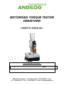
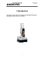
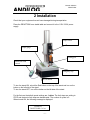
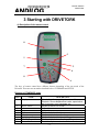
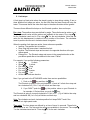
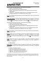
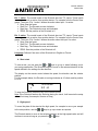
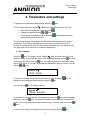
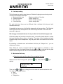
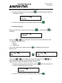
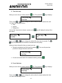
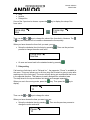
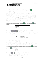
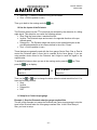
MOTORISED TORQUE TESTER
DRIVETORK
USER’S MANUAL
Your equipment reference :
N°: …………………………..…………… Date: ………………..
ANDILOG Technologies – 1 Rue Marcel Paul – 91300 MASSY - France
Tel : +33 820 888 202 – Fax : +33 820 888 902 – E-mail : [email protected]
Manuel utilisation
DRIVETORK
CONTENTS
1 Introduction.............................................................................................................................................................. 1
2 Installation ............................................................................................................................................................... 1
3 Starting with DRIVETORK .................................................................................................................................... 3
1.
Speed ....................................................................................................................................................... 4
2.
Limit stops............................................................................................................................................... 5
3.
Other options ........................................................................................................................................... 6
4.
Start a test ................................................................................................................................................ 7
5.
High speed............................................................................................................................................... 7
6.
Reset the position .................................................................................................................................... 8
4. Parameters and settings .......................................................................................................................................... 9
1.
Speed setting ........................................................................................................................................... 9
2.
Limit stop setting................................................................................................................................... 10
3.
Mechanical limit stop............................................................................................................................ 10
4.
Position limit stop ................................................................................................................................. 11
5.
Time limit stop ...................................................................................................................................... 12
6.
Force limit stop ..................................................................................................................................... 12
7.
Delay setting.......................................................................................................................................... 13
8.
Cycles setting ........................................................................................................................................ 14
9.
Use the foot pedal (Option) .................................................................................................................. 14
10.
Use the Inputs of the Drivetork............................................................................................................. 15
11.
Setup for a Centor torque gauge ........................................................................................................... 15
Example 1: Stop the Drivetork when the gauge reaches 2Nm........................................................................ 15
12.
Change the language ............................................................................................................................. 17
4. Security ................................................................................................................................................................. 18
1.
Security housing.................................................................................................................................... 18
2.
Overload protection (Optional)............................................................................................................. 18
3.
Current security..................................................................................................................................... 18
4.
Internal travel limit................................................................................................................................ 19
5.
Transmission error ................................................................................................................................ 19
6.
Security stop.......................................................................................................................................... 19
7.
Fuse........................................................................................................................................................ 19
8.
External wiring...................................................................................................................................... 19
Manuel utilisation
DRIVETORK
1 Introduction
WE THANK YOU VERY MUCH FOR CHOSING OUR DRIVETORK SYSTEM AND
ARE HOPING YOU WILL BE FULLY SATISFIED.
-1-
Manuel utilisation
DRIVETORK
2 Installation
Check that your equipment has not been damaged during transportation.
Place the DRIVETORK on a stable table and connect it to the 110V / 220V power
supply.
Torque sensor
Torque gauge
Turning part
Motorized stand
control
Emergency stop
On/Off button
To turn the stand ON, unlock the Red button on the top of the stand and turn on the
button on the left side of the stand.
To turn the stand OFF, turn off the button on the left side of the stand.
For the first use the default speed settings are 1 rd/mn. The limit stops are setting to
STOP and electronic limit stops are desactivated. The number of cycles is 0.
When turned ON, the following message is displayed:
ANDILOG
DRIVETORK v2.0 us
-1-
Manuel utilisation
DRIVETORK
When not running the screen flashes and displays the displacement and speed
values; the speed setting values and the electronical limit stops distance.
The digital controller will allow you manage the frame and set up test stand
parameters.
-2-
Manuel utilisation
DRIVETORK
3 Starting with DRIVETORK
A) Description of the remote control
0
3
1
2
7
4
8
6
5
The keys of remote control have different features depending of the run mode of the
Drivetork. There are two run modes described below: STANDARD and SETUP.
Running in STANDARD mode
KEY #
NAME
0
Display
1
2
3
4
5
6
7
8
MENU button
+ button
- button
Up button
Down button
Up high speed button
Down high speed button
Reset
DESCRIPTION
Gives information regarding the status of the
Drivetork. Shows displacement value, speed value,
test in process, error messages, etc
Access to the SETUP mode
No function
No function
Start in clockwise direction
Start in anti-clockwise direction
Start in clockwise direction at full speed
Start in anti-clockwise direction at full speed
Reset the displacement value if the motor is
-3-
Manuel utilisation
DRIVETORK
stopped
IF THE MOTOR IS RUNNING, PRESS ANY KEY TO STOP THE MACHINE
Running in SETUP mode
KEY #
1
2
3
4
5
6
7
8
NAME
MENU button
+ button
- button
Up button
Down button
Up high speed button
Down high speed button
Reset
DESCRIPTION
Access to STANDARD mode and save data
Select the next parameter
Select the previous parameter
Increase parameter value by 1 unit
Decrease parameter value by 1 unit
Increase parameter value by 100 units
Decrease parameter value by 100 units
No function
NOTE: When the motor is stopped, you can reset the angle value to zero by pressing
the Reset key. This makes the angle origin relative.
The DRIVETORK can run in two modes: "pulse" or "Continuous":
B) Emergency stop
The Drivetork test stand has a power emergency stop switch on the middle of the
cover. This emergency stop turns off all power to the test stand. To restart the
Drivetork, you must unlock this switch by rotating it clockwise.
Note: If you stop the Drivetork with the emergency stop during a test, it is possible
that the angle value was not saved correctly. You must check this value when you
turn on the Drivetork after an emergency stop.
If the motor is off when you use the emergency stop to turn off your equipment, the
angle value is saved correctly.
C) Settings
Before using your equipment, review all of the available parameters to help you
understand the numerous features of this tester.
1. Speed
The first two menus are to setup the clockwise and anti-clockwise speeds. These two
speeds can be managed separately. Use the
&
keys to increase or decrease
&
keys to increase and decrease the speed by
the value by 0.05rd/min and the
5 rd/min.
-4-
Manuel utilisation
DRIVETORK
2. Limit stops
A limit stop is a fixed point where the stand is going to stop during rotating. If two or
three different limit stops are active, the first limit stop the stand meets will stop the
tester. This means that all the other limit stops in the same direction will be ignored.
There are three different limit stops on the Drivetork: position, time and torque.
Pos. stop: The position stops are defined by angle. These limits can be active or not.
The displacement value and the actions are available in the menus “Pos. stop
“
for the clockwise travel and in “Pos. stop
” for the anti-clockwise. Note that the
value for this displacement is relative to the 0 position of the frame. The clockwise
travel is positive and the anti- clockwise travel is negative.
When the position limit stops are active, three actions are possible:
• Inactive: The position limit is inactive
• Stop: Stop the frame when it reaches this limit
• Inverter: The Drivetork stops and moves in the opposite direction at the predefine speed
• Delayed Inv.: The Drivetork stops and moves in the opposite direction at the
pre-define speed after a time defined in the menu “Pause”
For example, if you put the following parameters:
• Speed
5 rd/min
• Speed
2 rd/min
• Pos. stop
Stop
• Pos. stop
2 rd
• Pos. stop
Inverter
• Pos. stop
-1 rd
• All the other limits are Inactive.
Now, if you go back to the STANDARD mode, there are two possibilities:
1. Push on the
key and then the
key:
The Drivetork is going to turn anti-clockwise 1 round at 2 rd/min then stop and
turn clockwise 3rd (1 rd + 2 rd) at 5 rd/min and then stop
2. If you DON’T push the
key, the position value on your Drivetork is
for example +0.5rd and then you push the
key:
The Drivetork is going to turn anti-clockwise of 1.5rd (+0.5 – (-1)) at 2rd/min then stop
and turn clockwise 3rd (1rd + 2rd) at 5rd/min and then stop
Note: The clockwise and anti- clockwise position limit stops DON’T work if the
Drivetork is in high speed mode
Time stop: The time stops are defined by a time of travel in seconds. These limits
can be active or not. The time and the actions are available in the menus “Time stop
“ for the clockwise travel and in “Time stop
” for the anti- clockwise.
-5-
Manuel utilisation
DRIVETORK
When the time limit stops are active, three actions are possible:
• Inactive: The time limit is inactive
• Stop: Stop the frame when it reaches this limit
• Inverter: The Drivetork stops and turns in the opposite direction at the predefine speed
• Delayed Inv.: The Drivetork stops and turns in the opposite direction at the
pre-define speed after a time defined in the menu “Pause”
Note: The clockwise and anti-clockwise time limit stops DON’T work if the Drivetork is
in high speed mode
Force stop (Option): The force stops are defined by force in Newtons. These limits
can be active or not. The force value and the actions are available in the menus
“Force stop
“ for clockwise travel and in “Force stop
” for anti-clockwise travel.
When the force limit stops are active, three actions are possible:
• Inactive: The force limit is inactive
• Stop: Stop the frame when it reaches this limit
• Inverter: The Drivetork stops and moves in the opposite direction at the predefined speed
• Delayed Inv.: The Drivetork stops and moves in the opposite direction at the
pre-defined speed after a time defined in the menu “Pause”
Note: The clockwise and anti-clockwise force limit stops DON’T work if the Drivetork
is in high speed mode
Pause: Define the time the Drivetork is going to stop when it reaches one of the stop
limits defined above setup in “Delayed Inv.”. This delay is available in the menus
“Pause
“ for the anti-clockwise limit stops and in “Pause ” for the clockwise limit
stops.
Cycle: Define the number of cycles (between 1 and 255) the Drivetork is going to
perform when it reaches clockwise and anti-clockwise limit stops configured in
“Inverter” or “Delayed Inv”.
3. Other options
Pedal action: It’s possible to plug a foot pedal into the Drivetork. This menu defines
what the Drivetork does after receiving the command from the pedal. The different
actions are:
• Inactive: The pedal is inactive
• Stop: Stop the frame when pedal is pushed
• Start Pos.: The Drivetork moves clockwise
• Start Neg.: The Drivetork moves anti-clockwise
• ZERO: Put the position of the Drivetork to 0
In standard mode, when the Drivetork is moving, the pedal has the same feature as
any key of the control panel. It means that if you push on the pedal during a test, the
stand will stop.
-6-
Manuel utilisation
DRIVETORK
Ext. 1 action: The control board of the Drivetork has two TTL inputs. These inputs
are used to launch an action from another device. For example from the Centor force
gauge. The menu “Ext. 1 action” defines the action when input 1 is active:
• Stop: Stop the frame
• Start Pos.: The Drivetork moves clockwise
• Start Neg.: The Drivetork moves anti-clockwise
• ZERO: Set the position of the Drivetork to 0
Ext. 2 action: The control board of the Drivetork has two TTL inputs. These inputs
are used to launch an action from another device. For example from the Centor force
gauge. The menu “Ext. 2 action” defines the action when the input 2 is active:
• Stop: Stop the frame
• Start Pos.: The Drivetork moves clockwise
• Start Neg.: The Drivetork moves anti-clockwise
• ZERO: Sets the position of the Drivetork to 0
Language: Defines if the menu of the Drivetork is in English or French.
4. Start a test
To start a test, you just push the
or
keys to go up or down following you’re
your setup parameters. The Drivetork begins to move in the selected direction at the
speed defined in the settings for this direction.
The display on the remote control shows the speed, the direction and the relative
position.
For the example below, the Drivetork is turning clockwise at 10 rd/min and its position
is +2 rd.
+
10.0 rd/min
2.0 rd
To stop the Drivetork, press any key of the remote control.
Note: If the Drivetork reaches any limit stop during the travel, it will execute the setup
defined limit stop (for example, Inverter or Stop)
5. High speed
To move the plate of the stand at the high speed, for example to move your sample
to the start position, use the & keys to go up or down as required.
The Drivetork starts to move in the selected direction at the high speed value and will
continue to move as long as you press the or keys.
-7-
Manuel utilisation
DRIVETORK
Example of the display during a high speed down travel:
-
35.0 rd/min
3.00 rd
Note: During high-speed travel, only the “Sensor Limit Stops” are active. The
other limits (time, position…) are all inactive.
The high-speed mode should be used only to move the crosshead to the start
position. When Drivetork setup is done, the high-speed mode is not required.
6. Reset the position
To set the position of the Drivetork to 0.00rd, press the
stopped
-8-
key when the motor is
Manuel utilisation
DRIVETORK
4. Parameters and settings
To access to the parameters and settings, press the
The first parameter is the speed
key.
. When you are in this first menu, you can:
•
•
Go to the next parameter by pressing the
or
keys
Change the parameter with
•
Go back to the standard mode by pressing
automatically saved and active.
. All the parameters are
The method to change the parameters in the setup mode is the same for all the
parameters. The features available are shown in the menu depending of your
settings. For example the menu for the cycles is available only if you setup at least
one down and one up limit stop in Inverted or delayed Inv.
1. Speed setting
Press the
key. The display shows “Speed
” and the actual value of the up
key and
speed in rd/min. To increase the value of the clockwise speed press the
key. The speed increases or decreases with a
to decrease this value, press the
step of 0.05 rd/min. If you want to change the speed with a step of 5 rd/min, you can
use the & keys.
Speed
10.00 rd/min
To check your setting and go back to the running mode, press the
key.
change the anti-clockwise speed setting, press the
If you press the
key. To
key, the display is now:
Speed
150.00 mm/min
To increase the value of the anti-clockwise speed press the
key and to decrease
key. The speed increases or decreases with a step of 0.05
this value, press the
rd/min. If you want to change the speed with a step of 5 rd/min, you can use the &
keys.
To check your setting and go back to the running mode, press the
-9-
key.
Manuel utilisation
DRIVETORK
2. Limit stop setting
The limit stops are used to setup how your Drivetork is going to move during a test.
There are four different limit stops:
• Mechanical limit stop
Maximum rotation of the plate
• Position limit stop
Virtual, setup in rd
• Time limit stop
Virtual, setup in seconds
• Force limit stop
Virtual, setup in Nm
For each limit stop, there are two different kinds: clockwise limit stop and anticlockwise limit stop.
It’s possible to have any or all of the limit stops active in the same time. The Drivetork
will do the action that corresponds to the first limit stop reached. All the other limit
stops will be ignored.
We strongly recommend the use of only one kind of virtual limit stop per test.
All the limit stops can be setup to stop the motor, reverse the travel direction, reverse
the travel direction after a pause, or inactive. The setup of the clockwise and anticlockwise stop limits is independent. Only the pause time is the same for all the limit
stops.
By selecting a clockwise and anti-clockwise limit stop in “Delayed Inv.”, you can
create travel cycles.
Note: When the motor is stopped and the stand reaches a clockwise or anticlockwise limit stop, the display shows the sign
or
to indicate that the plate
reached a limit stop and can not move the tester beyond these points.
3. Mechanical limit stop
a) Setup the action and the value of the mechanical limit stop
When you are in the running mode, press the
display:
key. Then press the
key to
Sensor stop
Inactive
Then use the
or
keys to change the action when the stand reaches this limit.
You have the following choices:
• Stop
• Inverter
• Delayed Inv.
- 10 -
Manuel utilisation
DRIVETORK
When you have chosen the parameter you want, you can:
•
. Then use the previous process
Setup the clockwise limit stop by pressing
to change the action
Sensor stop
Inactive
•
Or save and come back to the standard mode by pressing
4. Position limit stop
When you are in the run mode, press the Press the
to display:
key. Then press the
key
Pos. stop
Inactive
Then use the
or
keys to change the action when the stand reaches this limit.
You have the following choices:
• Stop
• Inverter
• Delayed Inv.
If one of the 3 previous is chosen, press the
position value.
Pos. stop
Stop
key to display the setup of the
Pos. stop
2 rd
Then use the
or
keys to change the value of the travel limit. The
are available too to increase and decrease the speed quickly.
When you have chosen the position you want, you can:
•
Setup the clockwise position limit stop by pressing
process to change the action and value
Or save and come back to the standard mode by pressing
- 11 -
keys
. Then use the previous
Pos. stop
Inactive
•
&
Manuel utilisation
DRIVETORK
5. Time limit stop
When you are in the run mode, press the
key. Then press the
key to display:
Time stop
Inactive
Then use the
or
keys to change the action when the stand reaches this limit.
You have the following choices:
• Stop
• Inverter
• Delayed Inv.
If one of the 3 previous is chosen, a press on the
time value.
Time stop
Inverter
key will display the setup of the
Time stop
30
Then use the
or
keys to change the value of the time limit in seconds. The
keys are available too to increase or decrease the time quickly.
&
When you have chosen the time you want, you can:
•
Setup the clockwise time limit stop by pressing
process to change the action and value
. Then use the previous
Time stop
Inactive
•
Or save and come back to the standard mode by pressing
6. Force limit stop
When you are in the run mode, press the
key. Then press the
key to display:
Force stop
Inactive
Then use the
or
keys to change the action when the stand reaches this limit.
You have the following choices:
- 12 -
Manuel utilisation
DRIVETORK
•
•
•
Stop
Inverter
Delayed Inv.
If one of the 3 previous is chosen, a press the
force value.
key to display the setup of the
Force stop
Stop
Force stop
100
Then use the
or
keys to change the value of the force limit in Newtons. The
& keys are available too to increase or decrease the force quickly.
When you have chosen the force limit you want, you can:
•
Setup the clockwise force limit stop by pressing
process to change the action and value
. Then use the previous
Force stop
Inactive
•
Or save and come back to the standard mode by pressing
7. Delay setting
If at least one limit stop is set to “Delayed Inv.”, the parameter “Pause” is available in
the menu. This menu allows you to set how long the Drivetork is going to stop after
reaching one of the limit stops. The motor will stop during set seconds and then move
in the opposite direction. This features is mainly designed the relaxation tests.
The stop times for the top and bottom limit stops are managed separately:
When you are in the running mode, press the
display:
key. Then press the
key to
Pause
10
Then use the
or
keys to change the value.
When you have chosen the time you want, you can:
•
Setup the clockwise time by pressing
change the action and value
Pause
10
- 13 -
. Then use the previous process to
Manuel utilisation
DRIVETORK
•
Or save and come back to the standard mode by pressing
8. Cycles setting
When at least one bottom and one top stop limit are set to “Delayed Inv.”, the menu
“Cycle” is available.
A cycle is performed when the Drivetork reaches one bottom and one top limit. The
number of cycles decreases by one when the Drivetork reaches the first limit. Then
again one when it reaches the 3rd limit and another one for the 5th limit… until the
number of cycles is 0. When cycle is 0, the Drivetork stops when it reaches a limit.
If you want to stop the Drivetork during a cycle, press any key on the remote control.
The cycle counter is then set to zero.
When you are in the running mode, press the
display:
key. Then press the
key to
Cycles
34
Then use the
&
&
&
keys to change the value from 0 to 255.
In running mode, the cycles counter is shown on the right of the display and
decreases one cycle for each cycle done.
3 rd/min
+ 3.24 rd
N34
9. Use the foot pedal (Option)
It’s possible to use a pedal to send instructions to the Drivetork. In fact the pedal
simulates keys of the remote control. Most of the time this configuration is used when
the Drivetork does same repetitive test and makes the work easier for the operator.
To enable this feature, when you are in the running mode, press the
press the
key. Then
key to display:
Pedal
Inactive
Then use the
or
keys to change the action. You have the following choices:
• Inactive
• Stop -> Stop the test stand when you use the pedal
• Start Pos. -> Start the Drivetork turning clockwise
- 14 -
Manuel utilisation
DRIVETORK
•
•
Start Neg. -> Start the Drivetork turning anti-clockwise
Zero -> Set the position to zero
Then go to back to the running mode the
key.
10. Use the Inputs of the Drivetork
The Drivetork series has two TTL inputs that are activated by the detection of a falling
edge signal. This detection can cause the following actions:
• Stop: Stop the frame when it reaches this limit
• Inverter: The Drivetork stops and moves in the opposite direction at the predefined speed
• Delayed Inv.: The Drivetork stops and moves in the opposite direction at the
pre-defined speed after a time frame defined in the menu “Pause”
• Zero -> Set the position to zero
These features are generally used with the force gauge Centor Easy, Star or Dual to
control the Drivetork when a force limit is reached by the force gauge. If you are
using another device linked to the Drivetork, don’t forget to reset the signal to the
original value.
To enable this feature, when you are in the running mode, press the
press the
key. Then
key to display:
Ext. 1 action
Inactive
OR
Ext. 2 action
Inactive
Then use the
or
keys to change the action when the stand reach this limit. You
have the following choices:
• Stop
• Inverter
• Delayed Inv.
• RAZ
11. Setup for a Centor torque gauge
Example 1: Stop the Drivetork when the gauge reaches 2Nm
The aim of this example is to setup the Drivetork and Centor torque gauge to stop the
travel of the Drivetork when the force gauge reaches 2Nm. In the Centor Easy or
Star, you have to setup:
- 15 -
Manuel utilisation
DRIVETORK
LIMITS
Chan. I
UNIT
T1 :
T2 :
DEFAULT
BEEP
TYPE
YES
Nm
2
2
INT
NO
COM
Pedal
INPUTS
MENU
TDX
TAR
OUTPUTS
Top1
F
Anal
Digi
RS232
NO
NO
NO
MENU
TDX
In the Centor Dual, you can setup a limit on the internal sensor or on the external one
independently and/or simultaneously. For that you have to setup:
LIMITS
Chan. I
UNIT
T1 :
T2 :
DEFAULT
BEEP
TYPE
Chan. E
UNIT
T1 :
T2 :
DEFAULT
BEEP
TYPE
MENU
INPUTS
YES
Nm
2
2
INT
NO
COM
YES
Nm
2
3
INT
NO
COM
TDX
Pedal
TAR
OUTPUTS
Top1
Top2
Anal
Digi
RS232
F
F
NO
NO
NO
MENU
TDX
Note: When the output of the Centor shows the parameter “F”, there is a voltage of
5V on the output pin of the connector (DB15). When the force gauge reaches the
limit the output becomes 0V and activates the input on the Drivetork.
To reset the output to 5V, press the
key of the torque gauge.
- 16 -
Manuel utilisation
DRIVETORK
12. Change the language
This last parameter is to change the language of the menu and messages on the
remote control of the Drivetork. The two languages available are French and English.
To enable this feature, when you are in the running mode, press the Press the
key. Then press the
key to display:
Language
English
- 17 -
Manuel utilisation
DRIVETORK
4. Security
1. Security housing
If your test stand is equipped security housing with a door, opening the door stops
the test stand and disables the remote control. To use the setup mode, you have to
close the door. When you close the door the stand will re-start the test from the door
open point. You must re-start your test from the beginning.
2. Overload protection (Optional)
If you use the option to stop the Drivetork when your gauge reaches a limit, you can
protect the Drivetork and your force gauge against overload.
For that you have to setup the force gauge, like this:
INPUTS
LIMITS
Chan. I
UNIT
T1 :
T2 :
DEFAULT
BEEP
TYPE
YES
Nm
2.85
2.85
INT
NO
COM
MENU
TDX
Pedal
TAR
OUTPUTS
Place here the maximum
capacity of your force gauge
less 5%, for example
3Nm-5% = 2.85Nm
Top1
F
Anal
Digi
RS232
NO
NO
NO
MENU
TDX
For that you have to setup the force gauge, like this:
Ext. 1 action
Stop
Be careful, due to the inertia of the motor, it’s possible that the Drivetork will not stop
instantaneously. So you should set a limit lower than the capacity of your gauge.
3. Current security
If the Drivetork detects too much current for any reason, the stand is going to stop
and you will have the following message:
Dist+
0.00 mm
SECURITY CURRENT
- 18 -
Manuel utilisation
DRIVETORK
You have to turn off the test stand and turn on again to reset this protection.
4. Internal travel limit
The Drivetork has internal travel limits to stop the test stand before it reaches the end
of the power screw. These travel limits cut the power supply of the motor in the
direction of the actual travel. You can move the test stand manually in the opposite
direction.
Note: After this kind of stop, the value of the displacement could be modified. You
have to check this value before doing another test.
5. Transmission error
If the remote control cannot communicate with the test stand (for example if the cable
is broken), the two systems launch a reset process and switch to a security mode to
stop the motor. You have to restart the test stand but your equipment probably needs
maintenance.
! SECURITY !
ERROR CODE # 6
6. Security stop
If the system detects that a command is not properly completed, the display shows:
! SECURITY !
Door / Overl / Pos
In this case you have to check the following:
• If you have security doors, please check that all the doors are closed
• If there is an overload on the motor, remove this overload
• If the stand is in a travel limit position, move the stand in the opposite direction
7. Fuse
If you cannot turn on your equipment, it’s possible that one of the two protective fuses
is open. In this case, unplug the Drivetork and open the door on the back. There are
2 fuses:
• One of 5 A 5X20 mm
• One of 200 mA 5X20 mm
8. External wiring
Using of foot pedal or inputs requires specific wiring connected on the side of the
column of the Drivetork.
- 19 -


![Figure 2-1 Diagramme explicatif du Guide de dépôt [PDF 65 ko]](http://vs1.manualzilla.com/store/data/006470718_1-63d115b2562e98e0cd17bb43f1223554-150x150.png)